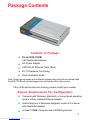
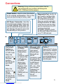
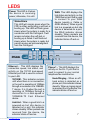
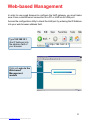
1
D-Link
DVG-1120M
VoIP Residential Gateway
Manual
Building Networks for People
(10/08/04)
Downloaded from www.Manualslib.com manuals search engine
Contents
Package Contents ................................................................................3
Introduction............................................................................................4
Connections .......................................................................................... 5
Features and Benefits ...........................................................................6
LEDs ....................................................................................................7
Web-based Management ......................................................................8
Technical Specifications ......................................................................29
Technical Support ................................................................................32
Warranty ..............................................................................................33
Registration ........................................................................................36
2
Downloaded from www.Manualslib.com manuals search engine
Package Contents
Contents of Package:
D-Link DVG-1120M
VoIP Residential Gateway
A/C Power Adapter
CAT5-RJ-45 Ethernet Cable (Blue)
RJ-11 Telephone Cord (Gray)
Quick Installation Guide
Note: Using a power supply with a different voltage rating than the one included with
the DVG-1120M will cause damage and void the warranty for this product.
If any of the above items are missing, please contact your reseller.
System Requirements For Configuration:
Computer with Windows, Macintosh, or Linux-based operating
system with an installed Ethernet adapter
Internet Explorer or Netscape Navigator version 4.0 or above,
with JavaScript enabled
At least 128MB of memory and a 500MHz processor
3
Downloaded from www.Manualslib.com manuals search engine
Introduction
The D-Link DVG-1120M VoIP Station Gateway links traditional telephone networks
to IP networks with conventional telephone devices such as analog phones or
fax machines.
The DVG-1120M includes two Foreign Exchange Subscriber (FXS) interfaces
with normal RJ-11 telephone connectors that provide voice/fax communication
over the IP network.
Two Ethernet ports are also provided. One Ethernet port is for a DSL/Cable
Modem or other WAN device, and the other is for connection to create a home
or small office LAN network.
The built-in DHCP server and Network Address Translation (NAT) function
automatically assigns IP addresses for LAN users, allowing multiple users to
share a single Internet connection. You can configure and monitor the DVG1120M via the Web browser. Telnet and SNMP management is also supported.
By routing calls over the Internet or any IP network, the DVG-1120M can reduce
or eliminate long distance or inter-office phone charges. Corporations can also
enjoy the benefits of network consolidation and reduction of leased lines by
relying on the Internet service providers to deliver toll-quality voice
communications over the IP networks.
4
Downloaded from www.Manualslib.com manuals search engine
Connections
Warning! Using a different power adapter than the
one included with your purchase will damage the
DVG-1120M and void the warranty.
Reset Switch Used to return the device
to its original configuration. This is the
same as performing a factory reset.
AC Power Connector Use the
included power adapter. If you use
a power adapter other than the
one included with the product you
will damage the device and void
the warranty on this product.
Diagnostic Port An RJ-14
port used to configure the
device. (User needs a RJ14 to RS-232 converter).
Plug one end of a straightthrough wired RJ-14 cable
to the device and the other
end to a serial port of a PC
running a terminal
emulation program (such
as Microsoft HyperTerminal)
or a VT-100 terminal.
2
PSTN/VoIP
Switch to
select PSTN
or VoIP mode
When the
switch is in
the down
position,
Phone1/2 will
be in VoIP
Mode.
When the
switch is in
the up
position,
Phone1/2 will
be configured
to PSTN
Mode.
Ethernet WAN
A 10Mbps
Ethernet port
fitted with an
RJ-45
connector used
to connect the
VoIP gateway
to a WAN
device (e.g.
Cable/ADSL
Modem). This
port accepts
Category 3, 4
or 5 UTP
cabling with an
RJ-45
connector.
Downloaded from www.Manualslib.com manuals search engine
Ethernet LAN
A 10/100Mbps
dual-speed
Ethernet port
fitted with an
RJ-45
connector used
to connect the
VoIP gateway to
a LAN device
(hub, switch,
PC, etc.). This
port accepts
Category 5 or
better UTP
cabling with an
RJ-45
connector.
1
Phone 1
Normal RJ-11 phone
jack used to connect
to a telephone or fax
machine. Plug your
normal telephone or
fax machine directly
into this jack.
5
Features & Benefits
One analog FXS interface port accepting an RJ-11 connector to facilitate
a VoIP connection
One 10Mbps WAN port for connecting to a DSL/Cable Modem or other
WAN devices
One 10/100Mbps LAN port for connecting to a local network
IP address assignment using DHCP (Dynamic Host Configuration
Protocol) or static configuration
IP Routing support (RIP1, RIP2 and Static Routing)
Remote software download/update
Supports IP sharing to allow multiple users to access the Internet via a
single IP address
Built-in PPPoE function to support dial-up connection for broadband
technology
Supports Caller ID
Supports QoS to guarantee voice quality
Automatic Call Redirection (ACR) function support
VoIP line automatic selection (e.g. 110, 119)
VoIP routing table support
6
Downloaded from www.Manualslib.com manuals search engine
LEDS
Power This LED is lit when
the device is receiving
power; otherwise, it is unlit.
Status/Alarm
This LED will remain green when the
CPE is either performing a self-test or
booting up. The LED will flash green
slowly when the system is ready for a
connection with the Call Agent. It will
remain red when the self-test or
booting up is failed. It will flash red
slowly when the system is ready but
cannot receive an acknowledgment
from the Call Agent.
Ethernet - This LED displays the
connection speed, link status, and
activity on the 10/100 dual-speed
Ethernet port that is used to connect
to your LAN.
10/100M - This indicator remains
unlit when there is no connection,
or the port is operating at 10Mbps
through a connection to a 10BASET device. It is lit when the port is
operating at 100Mbps through a
connection to a dual-speed or
100BASE-TX Fast Ethernet
device.
Link/Act - When a good link to a
powered-up but idle device is
detected on a port, this indicator
shines steadily. When packets are
received from the device, the
indicator blinks off and on.
Downloaded from www.Manualslib.com manuals search engine
WAN This LED displays the
link status and activity on the
10M Ethernet port that is used
to connect to your WAN
device (usually a Cable or
ADSL Modem). When a good
link to a powered-up but idle
device is detected on a port,
the WAN indicator shines
steadily. When packets are
received from the device, the
indicator blinks off and on.
Phone 1 - This LED displays the
activity on the RJ-11 port that is
used to connect to your normal
telephone/fax machine line.
Hook/Ringing - When an offhook action is detected on a
phone port, this indicator shines
steadily. When a ringing signal
is received from the device, the
indicator blinks off and on.
7
Web-based Management
In order to use a web browser to configure the VoIP gateway, you must make
sure it has a valid Ethernet connection to a PC or LAN via its LAN port.
Access the configuration utility to check the LAN port by entering the IP Address
into your web browser address field.
Type 192.168.15.1
(the IP Address) into
the address field of
your browser.
http://192.168.15.1
Click on Login to the
Web-based
Management
module
8
Downloaded from www.Manualslib.com manuals search engine
Web-based Management (continued)
Setting Up the Connection
To configure the WAN port, please do the following:
Click on Configure WAN Port.
Manually input the
WAN IP Address here.
Then go to Start>Control
Panel>Network
Connections>Right-click local
area connection >select
Properties> double click Internet
Protocol (TCP/IP). The screen at
right will appear.
The VoIP gateway’s WAN port comes
with DHCP as default IP setting. If the
VoIP gateway cannot get the
assigned DHCP IP, it will use the
manual IP (default is 10.1.10.5 ) as
it’s default IP.
Make sure the PC is in the same IP
domain as the VoIP gateway. You
can do this by changing the IP
address of the PC as shown here.
Downloaded from www.Manualslib.com manuals search engine
9
Web-based Management (continued)
To configure the LAN port for the device, please do
the following:
Click on Configure LAN Port.
In this configuration menu, users can configure the LAN IP Address.
(Recommended for advanced users.)
By default the LAN IP Address is: 192.168.15.1
After you have configured your WAN and LAN ports you can click on Save
and Restart System in the Configuration menu, or you can continue to
configure the VoIP. After you have completed configuring the VoIP, you must
Save and Restart the System or your changes will not be saved.
10
Downloaded from www.Manualslib.com manuals search engine
Web-based Management (continued)
Configure LAN Port > Proxy DNS
State - This toggles
Enable and Disable for
the
Proxy
DNS
function.
Proxy
DNS
IP
Address - Enter the
Proxy DNS IP address
if instructed by your
service provider.
Click Save to save the settings.
Configure LAN Port > Bridge Mode
Bridge Mode - This
toggles On and Off to
turn NAT on or off for
Static Public IP
assignment.
Click Save to save the settings.
11
Downloaded from www.Manualslib.com manuals search engine
Web-based Management (continued)
Configure LAN Port > DHCP Configuration > Dynamic IP Assignment
Use the Dynamic IP
Assignment
to
configure the device to
act as a DHCP server
for the LAN.
The items on this
window are described
below:
Default Gateway - This specifies the Gateway IP Address that will be assigned
to and used by the DHCP clients.
Start IP Address -This is the base (starting) address for the IP pool of
unassigned IP addresses.
IP Range - This is the range of contiguous, IP addresses above the base IP
Address above.
Netmask - This mask informs the client, how the destination IP address is to
be divided into network, subnet, and host parts. The netmask has ones in the
bit positions in the 32-bit address which are to be used for the network and
subnet parts, and zeros for the host part.
Leased Time - This specifies the amount of time (in seconds) a client can
lease an IP address, from the dynamically allocated IP pool.
DNS Server IP - This specifies the Domain Name System server, used by the
DHCP clients using leased IP addresses, to translate hostnames into IP
addresses or vice-versa.
WIN Server IP - Some LANs may require using WINS servers; enter the IP
address of the WINS server or leave blank.
Domain Name - Enter a domain name for the network group or leave blank.
State - This toggles Disable and Enable for the DHCP function.
Click Save to save the settings.
Downloaded from www.Manualslib.com manuals search engine
12
Web-based Management (continued)
Configure LAN Port > DHCP Configuration > Static IP Assignment
The
Static
IP
Assignment functions
in much the same
way as the Dynamic IP
Assignment. The only
difference is that a
particular IP address
can be assigned to a
particular host. The
host is identified by the
MAC Address of its
NIC which must be
entered on next
screen.
Click the edit icon on the window above to access the second Static IP
Assignment window:
The items on this
window are described
below:
Index - Choose the
index number that you
would like to edit (From
1 to 4).
MAC Address - This
specifies the physical
address
of
the
particular host that will receive the below IP address.
IP Address - This is the static IP address to be assigned.
All other parameters (Netmask, Gateway, DNS Server IP, WINS Server IP,
Domain Name and State) are identical to those in the Dynamic IP Assignment,
in the previous section.
Click Save to save the settings.
Downloaded from www.Manualslib.com manuals search engine
13
Web-based Management (continued)
Configure LAN Port > NAT Configuration
Select enabled or
disabled for the NAT
function.
Click Save to save the
settings.
Configure LAN Port > NAT Configuration > Virtual Server Configuration
This window allows
you to view the current
virtual server
configuration settings.
Click the edit icon on this window to access the second Virtual Server
Configuration window:
14
Downloaded from www.Manualslib.com manuals search engine
Web-based Management (continued)
Configure LAN Port > NAT Configuration > Virtual Server Configuration
(continued)
The items on this
window are described
below:
Index - Choose the
index number that you
would like to edit (Form
1 to 6).
Protocol - Choose the
protocol either TCP or
UDP.
Global Port Range Enter the designated
TCP or UDP protocol port number for the particular protocol packet you wish to
redirect.
Local Port Range - Enter the port number used by the designated host on the
LAN or use a well-known port.
Server IP - Enter the IP address of the local designated host computer or
device.
State - This toggles Disable and Enable for the Virtual Server Configuration
function.
Click Save to save the settings.
15
Downloaded from www.Manualslib.com manuals search engine
Web-based Management (continued)
Configure LAN Port > NAT Configuration > Dynamic NAT
This window allows you
to view the current
Dynamic NAT settings.
Click the edit icon on
this window to access
the second Dynamic
NAT window:
The items on this
window are described
below:
Index - Choose the
index number that you
would like to edit (Form
1 to 6).
Global IP Start - Enter
the beginning designated
IP address for the
particular range of
packets you wish to
redirect
to
local
addresses.
Global IP End - Enter the end designated IP address for the particular range of
packets you wish to redirect to local addresses.
Local IP Start - Enter the beginning designated IP address for the particular
range of packets you wish to redirect to Global addresses.
Local IP End - Enter the end designated IP address for the particular range of
packets you wish to redirect to Global addresses.
State - This toggles Disable and Enable for the Dynamic NAT function.
Click Save to save the settings.
Downloaded from www.Manualslib.com manuals search engine
16
Web-based Management (continued)
Configure LAN Port > NAT Configuration > Static NAT
This window allows you
to view the current Static
NAT settings.
Click the edit icon on
this window to access
the second Static NAT
window:
The items on this
window are described
below:
Index - Choose the index number that you would like to edit (Form 1 to 6).
Local IP Address - Enter the designated IP address for the packet you wish to
redirect to a Global address.
Global IP Address - Enter the designated IP address for the packet you wish
to redirect to a Local address.
State - This toggles Disable and Enable for the Static NAT function for this
index.
Click Save to save the settings.
Downloaded from www.Manualslib.com manuals search engine
17
Web-based Management (continued)
Configure LAN Port > Routing > RIP
Select to use RIPv1,
RIPv2 or On (both
versions) for the LAN
and WAN interface.
To disable both
versions of RIP
select Off.
Click Save to save
the settings.
RIP - Routing
Information Protocol
that specifies how
routers exchange
information. With RIP,
routers periodically
exchange entire tables.
Configure LAN Port > Routing > Static Route Configuration
Use Static Routing to
specify a route used
for data traffic within
your WAN or LAN.
This can be used to
specify that all
packets destined for
a particular subnet
use a predetermined
gateway.
Click the edit icon on
the window above to
access the second
Static Route
Configuration
window:
18
Downloaded from www.Manualslib.com manuals search engine
Web-based Management (continued)
Configure LAN Port > RIP > Static Route Configuration (continued)
The items on this
window are described
below:
IP Address - Type in the IP Address of the subnet or device where packets are
routed.
Subnet Mask - Type in an appropriate subnet mask that allows the static
route to function.
Gateway - Type in the IP Address of the gateway used for traffic destined for
the specified subnet or device.
Interface - Select WAN or LAN Interface.
Metric - Type in the maximum number of hops allowed for the static route.
State - Enable or disable the route.
Click Save or Clear to Save or Clear the settings.
19
Downloaded from www.Manualslib.com manuals search engine
Web-based Management (continued)
Firewall Rules
Firewall Rules is an
advance feature used
to deny or allow traffic
from passing through
the device. The filtering
sets are sets of rules
defined in the menus
shown below.
Click the edit icon on
the window above to
access the Firewall
Rules window for the
first rules set:
Type in an appropriate
identifying comment for
the Firewall Rules set.
When you are finished
defining the rules for
each set, select
enabled or disabled
to enable or disable the
listed Firewall rules
sets.
Click Save button to
save the settings.
Click the edit icon on the window above to access the third IP Filter window,
shown on the following page:
20
Downloaded from www.Manualslib.com manuals search engine
Web-based Management (continued)
Firewall Rules (continued)
Comment- Type in an
appropriate identifying
comment for the rule.
Pass or Block- Select
Pass or Block to
perform this action on
packets as defined
below.
Direction- Select In or
Out to pass or block
packets coming in or
going out of the
network.
Protocol-Select IGMP, TCP, UDP or All to pass or block packets of that
protocol type.
Source- Type in the source IP Address and select the Subnet Mask to pass
or block packets from that IP Address.
Destination- Type in the destination IP Address and select the Subnet Mask
to pass or block packets destined to that IP Address.
Port Filter Rule- UDP and TCP packets only. Select a range of ports to
pass or block. Use the following guide to define the port or port range (Start
Port and End Port):
< : specifies the port numbers less than and equal to the Start Port
number
> : specifies the port numbers greater than and equal to the Start Port
number
= : sets the port number equal to the Start Port if there is no End Port
specified; if an End Port number is specified, this defines a range of
ports to filter. The range is defined as the port numbers between the Start
Port and End Port, including the Start and End Port numbers.
≠ : the port number does not equal the Start Port if there is no End Port
specified; if an End Port number is specified, this defines a range of
ports not to filter. The range is defined as the port numbers between
the Start Port and End Port, including the Start and End Port numbers.
21
Downloaded from www.Manualslib.com manuals search engine
Web-based Management (continued)
Firewall Rules (continued)
TCP Flag - Select enabled or disabled to enable or disable the filter rule as
defined in the menu.
TCP Packet Options - Optional TCP packet options include: Acknowledgement,
Push, Reset, SYN, and FIN. Consult a certified technician before selecting any
of these advanced options.
Filter Rule State - Select enabled or disabled to enable or disable the filter
rule as defined in the menu.
Click Save or click Clear to Save or Clear the settings.
MAC Filter
MAC (Media Access
Control) Filters are
used to deny or allow
LAN (Local Area
Network)
computers from
accessing the Internet
and network by their
MAC address.
Click the edit icon on the window above to access the MAC Filter window,
shown on the following page:
22
Downloaded from www.Manualslib.com manuals search engine
Web-based Management (continued)
MAC Filter (continued)
The items on this
window are described
below:
Index - This is the
index number that you
are editing (1-16).
MAC Address - Enter
the MAC address of the
client that will be
filtered.
State - This toggles Disable and Enable for the MAC address filtering function
for this index.
Click the Save button to save the settings.
Configure Pass Through Mode
The device supports VPN
(Virtual Private Network)
pass-through for both
PPTP (Point-to-Point
Tunneling Protocol) and
IPSec (IP Security). Once
VPN pass-through is
enabled, there is no need
to open up virtual
services. Multiple VPN
connections can be made
through the device. This
is useful when you have
many VPN clients on the
LAN.
PPTP Pass Through / IPSec Pass Through - This toggles Disable and
Enable for the Pass Through function.
Click the Save button to save the settings.
23
Downloaded from www.Manualslib.com manuals search engine
Web-based Management (continued)
Statistics > WAN Internet Connection Statistics
This window displays
a variety of WAN
Connection statistics.
Statistics > Phone Port Statistics
This window displays
a variety of Phone
Port statistics.
24
Downloaded from www.Manualslib.com manuals search engine
Web-based Management (continued)
Configuration Restore and Backup
The current system
settings can be saved
as a file onto the local
hard drive. The saved
file or any other saved
setting file created by
the DVG-1120M can be
uploaded into the unit.
To restore a system
settings file, click on
Browse to search the
local hard drive for the
file to be used.
To backup the current system settings, click on Backup and the following window
will appear:
Click on the Save
button and select the
location on your hard
drive to save the file to.
25
Downloaded from www.Manualslib.com manuals search engine
Web-based Management (continued)
Factory Reset
Before performing a Factory Reset, be absolutely certain that this is what you
want to do. Once the reset is done, all of the device’s settings stored in NVRAM will be erased and restored to values present when the device was
purchased.
Click on Reset to Factory Default to reset the NV-RAM to the default values
that were present when you purchased the device.
Note: After performing the Factory Reset, make sure to redefine the IP
settings for the device in the IP Configuration menu. Then perform a
Restart System on the device. After these three procedures are performed,
your Factory Reset is complete.
Click on Reset without losing user settings to reset the unit. This resets all
settings except IP, PPPoE username/password, Notify Entity, RGW name, and
DNS settings.
26
Downloaded from www.Manualslib.com manuals search engine
Web-based Management (continued)
Save and Restart System
After the settings have been saved to NV-RAM, they will become the default
settings for the device, and they will be used every time it is powered on, reset
or rebooted. The only exception to this is a factory reset, which will clear all
settings and restore the unit’s settings back to their initial values, which were
present when the device was purchased.
Click on Save Configuration at the bottom of the window to save the system
settings to NV-RAM.
Advanced
This section contains advanced configuration settings for the DVG-1120M VoIP
Station Gateway. Please consult a certified technician before making any
changes to the Advanced menu.
27
Downloaded from www.Manualslib.com manuals search engine
Web-based Management (continued)
About
This read-only window displays information about the DVG-1120M VoIP Station
Gateway such as: Device Type, MAC Address, Boot PROM Firmware,
Firmware Version, and DSP Version. The DSP Version will list
“Not yet loaded” until you initialize your unit.
28
Downloaded from www.Manualslib.com manuals search engine
Technical Specifications
Call Control Protocols Compliance:
MGCP
Voice Compression:
G.711 (A-law and u-law), G.723.1, G.729a
Analog Voice Ports:
Type: Loop-Start FXS interfaces
DTMF tone detection/generation
V.21/V.25 Modem/Fax tone detection
Echo Cancellation: G.165/G.168
Ethernet Ports:
WAN: 10BASE-T Ethernet port (MDI-II)
LAN: NWay 10/100BASE-TX Fast Ethernet ports (MDI-X)
IEEE 802.3 10BASE-T Ethernet compliance
IEEE 802.3u 100BASE-TX Fast Ethernet compliant
Quality of Service:
Voice service is prioritized over the data traffic
FAX support:
V.21, V.27ter, V.29, V.17 Modulation/Demodulation
Network Protocols:
TCP/IP, UDP, ARP, ICMP, TFTP, Telnet, SNMP, HTTP, RIP1/
RIP2
DHCP: Dynamic Host Configuration Protocol server and client
NAT: Network Address Translation
PPP over Ethernet Client
29
Downloaded from www.Manualslib.com manuals search engine
Technical Specifications (continued)
Network Management:
SNMP management agent base MIB II
Telnet provisioning
Manage functions through an intuitive web-based graphical
user interface
TFTP: The built-in Trivial File Transfer Protocol provides
firmware upgrade
Security:
Password Authentication Protocol/Challenge Handshake
Authentication Protocol (PAP/CHAP)
Administrative password through Web, Telnet and SNMP
Packet filter by IP Address, port number and protocol
LEDs:
General:
Power
Status/Alarm
Ethernet:
WAN: Link/Act
LAN: 10/100M, Link/Act
Phone 1:
Hook/Ringing
Dimensions:
To be determined
Number of Ports:
One 10BASE-T Ethernet port (WAN)
One 10/100BASE-TX Fast Ethernet port (LAN)
One loop-start FXS RJ-11 ports
One RJ-14 Console port
30
Downloaded from www.Manualslib.com manuals search engine
Technical Specifications (continued)
Power Supply:
AC-to-DC power adapter (provided)
DC Input: 12VDC/1A
Operating Temperature:
0-50°C
Storage Temperature:
-10-55°C
Humidity:
5% - 95% non-condensing
Safety:
UL/CUL
Emission (EMI):
FCC Class B
VCCI Class B
BSMI Class B
CE Class B
C-Tick Class B
31
Downloaded from www.Manualslib.com manuals search engine
Techni
cal Support
echnical
You can find software updates and user documentation on the D-Link website.
D-Link provides free technical support for customers within the United States and
within Canada for the duration of the warranty period on this product.
U.S. and Canadian customers can contact D-Link technical support through our
website, or by phone.
Tech Support for customers within the United States:
D-Link Technical Support over the Telephone:
(877) 453-5465
24 hours a day, seven days a week.
D-Link Technical Support over the Internet:
http://support.dlink.com
email:[email protected]
Tech Support for customers within Canada:
D-Link Technical Support over the Telephone:
(800) 361-5265
Monday to Friday 7:30am to 12:00am EST
D-Link Technical Support over the Internet:
http://support.dlink.ca
email:[email protected]
32
Downloaded from www.Manualslib.com manuals search engine
Warranty
Subject to the terms and conditions set forth herein, D-Link Systems, Inc. (“D-Link”) provides this Limited
warranty for its product only to the person or entity that originally purchased the product from:
D-Link or its authorized reseller or distributor and
Products purchased and delivered within the fifty states of the United States, the District of
Columbia, U.S. Possessions or Protectorates, U.S. Military Installations, addresses with an
APO or FPO.
Limited Warranty: D-Link warrants that the hardware portion of the D-Link products described
below will be free from material defects in workmanship and materials from the date of original retail
purchase of the product, for the period set forth below applicable to the product type (“Warranty
Period”), except as otherwise stated herein.
1-Year Limited Warranty for the Product(s) is defined as follows:
Hardware (excluding power supplies and fans) One (1) Year
Power Supplies and Fans One (1) Year
Spare parts and spare kits Ninety (90) days
D-Link’s sole obligation shall be to repair or replace the defective Hardware during the Warranty Period
at no charge to the original owner or to refund at D-Link’s sole discretion. Such repair or replacement will
be rendered by D-Link at an Authorized D-Link Service Office. The replacement Hardware need not be
new or have an identical make, model or part. D-Link may in its sole discretion replace the defective
Hardware (or any part thereof) with any reconditioned product that D-Link reasonably determines is
substantially equivalent (or superior) in all material respects to the defective Hardware. Repaired or
replacement Hardware will be warranted for the remainder of the original Warranty Period from the date
of original retail purchase. If a material defect is incapable of correction, or if D-Link determines in its sole
discretion that it is not practical to repair or replace the defective Hardware, the price paid by the original
purchaser for the defective Hardware will be refunded by D-Link upon return to D-Link of the defective
Hardware. All Hardware (or part thereof) that is replaced by D-Link, or for which the purchase price is
refunded, shall become the property of D-Link upon replacement or refund.
Limited Software Warranty: D-Link warrants that the software portion of the product (“Software”)
will substantially conform to D-Link’s then current functional specifications for the Software, as set forth
in the applicable documentation, from the date of original retail purchase of the Software for a period of
ninety (90) days (“Warranty Period”), provided that the Software is properly installed on approved
hardware and operated as contemplated in its documentation. D-Link further warrants that, during the
Warranty Period, the magnetic media on which D-Link delivers the Software will be free of physical
defects. D-Link’s sole obligation shall be to replace the non-conforming Software (or defective media)
with software that substantially conforms to D-Link’s functional specifications for the Software or to
refund at D-Link’s sole discretion. Except as otherwise agreed by D-Link in writing, the replacement
Software is provided only to the original licensee, and is subject to the terms and conditions of the
license granted by D-Link for the Software. Software will be warranted for the remainder of the original
Warranty Period from the date or original retail purchase. If a material non-conformance is incapable of
correction, or if D-Link determines in its sole discretion that it is not practical to replace the nonconforming Software, the price paid by the original licensee for the non-conforming Software will be
refunded by D-Link; provided that the non-conforming Software (and all copies thereof) is first returned
to D-Link. The license granted respecting any Software for which a refund is given automatically
terminates.
Non-Applicability of Warranty: The Limited Warranty provided hereunder for hardware and software
of D-Link’s products will not be applied to and does not cover any refurbished product and any product
purchased through the inventory clearance or liquidation sale or other sales in which D-Link, the sellers,
or the liquidators expressly disclaim their warranty obligation pertaining to the product and in that case,
the product is being sold “As-Is” without any warranty whatsoever including, without limitation, the
Limited Warranty as described herein, notwithstanding anything stated herein to the contrary.
Submitting A Claim: The customer shall return the product to the original purchase point based on its
return policy. In case the return policy period has expired and the product is within warranty, the
customer shall submit a claim to D-Link as outlined below:
The customer must submit with the product as part of the claim a written description of the
Hardware defect or Software nonconformance in sufficient detail to allow D-Link to confirm
the same.
33
Downloaded from www.Manualslib.com manuals search engine
The original product owner must obtain a Return Material Authorization (“RMA”) number from
the Authorized D-Link Service Office and, if requested, provide written proof of purchase of
the product (such as a copy of the dated purchase invoice for the product) before the
warranty service is provided.
After an RMA number is issued, the defective product must be packaged securely in the
original or other suitable shipping package to ensure that it will not be damaged in transit, and
the RMA number must be prominently marked on the outside of the package. Do not include any
manuals or accessories in the shipping package. D-Link will only replace the defective portion
of the Product and will not ship back any accessories.
The customer is responsible for all in-bound shipping charges to D-Link. No Cash on Delivery
(“COD”) is allowed. Products sent COD will either be rejected by D-Link or become the
property of D-Link. Products shall be fully insured by the customer and shipped to D-Link
Systems, Inc., 17595 Mt. Herrmann St., Fountain Valley, CA 92708. D-Link will not be
held responsible for any packages that are lost in transit to D-Link. The repaired or replaced
packages will be shipped to the customer via UPS Ground or any common carrier selected by
D-Link, with shipping charges prepaid. Expedited shipping is available if shipping charges are
prepaid by the customer and upon request.
D-Link may reject or return any product that is not packaged and shipped in strict compliance with the
foregoing requirements, or for which an RMA number is not visible from the outside of the package. The
product owner agrees to pay D-Link’s reasonable handling and return shipping charges for any product
that is not packaged and shipped in accordance with the foregoing requirements, or that is determined
by D-Link not to be defective or non-conforming.
What Is Not Covered: This limited warranty provided by D-Link does not cover: Products, if in D-Link’s
judgment, have been subjected to abuse, accident, alteration, modification, tampering, negligence, misuse,
faulty installation, lack of reasonable care, repair or service in any way that is not contemplated in the
documentation for the product, or if the model or serial number has been altered, tampered with, defaced
or removed; Initial installation, installation and removal of the product for repair, and shipping costs;
Operational adjustments covered in the operating manual for the product, and normal maintenance;
Damage that occurs in shipment, due to act of God, failures due to power surge, and cosmetic damage;
Any hardware, software, firmware or other products or services provided by anyone other than DLink; Products that have been purchased from inventory clearance or liquidation sales or other sales in
which D-Link, the sellers, or the liquidators expressly disclaim their warranty obligation pertaining to the
product. Repair by anyone other than D-Link or an Authorized D-Link Service Office will void this
Warranty.
Disclaimer of Other Warranties: EXCEPT FOR THE LIMITED WARRANTY SPECIFIED HEREIN, THE
PRODUCT IS PROVIDED “AS-IS” WITHOUT ANY WARRANTY OF ANY KIND WHATSOEVER INCLUDING,
WITHOUT LIMITATION, ANY WARRANTY OF MERCHANTABILITY, FITNESS FOR A PARTICULAR PURPOSE
AND NON-INFRINGEMENT. IF ANY IMPLIED WARRANTY CANNOT BE DISCLAIMED IN ANY TERRITORY
WHERE A PRODUCT IS SOLD, THE DURATION OF SUCH IMPLIED WARRANTY SHALL BE LIMITED TO
NINETY (90) DAYS. EXCEPT AS EXPRESSLY COVERED UNDER THE LIMITED WARRANTY PROVIDED
HEREIN, THE ENTIRE RISK AS TO THE QUALITY, SELECTION AND PERFORMANCE OF THE PRODUCT IS
WITH THE PURCHASER OF THE PRODUCT.
Limitation of Liability: TO THE MAXIMUM EXTENT PERMITTED BY LAW, D-LINK IS NOT LIABLE
UNDER ANY CONTRACT, NEGLIGENCE, STRICT LIABILITY OR OTHER LEGAL OR EQUITABLE THEORY
FOR ANY LOSS OF USE OF THE PRODUCT, INCONVENIENCE OR DAMAGES OF ANY CHARACTER,
WHETHER DIRECT, SPECIAL, INCIDENTAL OR CONSEQUENTIAL (INCLUDING, BUT NOT LIMITED TO,
DAMAGES FOR LOSS OF GOODWILL, LOSS OF REVENUE OR PROFIT, WORK STOPPAGE, COMPUTER
FAILURE OR MALFUNCTION, FAILURE OF OTHER EQUIPMENT OR COMPUTER PROGRAMS TO WHICH DLINK’S PRODUCT IS CONNECTED WITH, LOSS OF INFORMATION OR DATA CONTAINED IN, STORED ON,
OR INTEGRATED WITH ANY PRODUCT RETURNED TO D-LINK FOR WARRANTY SERVICE) RESULTING
FROM THE USE OF THE PRODUCT, RELATING TO WARRANTY SERVICE, OR ARISING OUT OF ANY
BREACH OF THIS LIMITED WARRANTY, EVEN IF D-LINK HAS BEEN ADVISED OF THE POSSIBILITY OF
SUCH DAMAGES. THE SOLE REMEDY FOR A BREACH OF THE FOREGOING LIMITED WARRANTY IS
REPAIR, REPLACEMENT OR REFUND OF THE DEFECTIVE OR NON-CONFORMING PRODUCT. THE MAXIMUM
LIABILITY OF D-LINK UNDER THIS WARRANTY IS LIMITED TO THE PURCHASE PRICE OF THE PRODUCT
COVERED BY THE WARRANTY. THE FOREGOING EXPRESS WRITTEN WARRANTIES AND REMEDIES
ARE EXCLUSIVE AND ARE IN LIEU OF ANY OTHER WARRANTIES OR REMEDIES, EXPRESS, IMPLIED OR
STATUTORY
34
Downloaded from www.Manualslib.com manuals search engine
Governing Law: This Limited Warranty shall be governed by the laws of the State of California. Some
states do not allow exclusion or limitation of incidental or consequential damages, or limitations on how
long an implied warranty lasts, so the foregoing limitations and exclusions may not apply. This limited
warranty provides specific legal rights and the product owner may also have other rights which vary
from state to state.
Trademarks: D-Link is a registered trademark of D-Link Systems, Inc. Other trademarks or registered
trademarks are the property of their respective manufacturers or owners.
Copyright Statement: No part of this publication or documentation accompanying this Product may
be reproduced in any form or by any means or used to make any derivative such as translation,
transformation, or adaptation without permission from D-Link Corporation/D-Link Systems, Inc., as
stipulated by the United States Copyright Act of 1976. Contents are subject to change without prior
notice. Copyright© 2002 by D-Link Corporation/D-Link Systems, Inc. All rights reserved.
CE Mark Warning: This is a Class B product. In a domestic environment, this product may cause radio
interference, in which case the user may be required to take adequate measures.
FCC Statement: This equipment has been tested and found to comply with the limits for a Class B
digital device, pursuant to part 15 of the FCC Rules. These limits are designed to provide reasonable
protection against harmful interference in a residential installation. This equipment generates, uses, and
can radiate radio frequency energy and, if not installed and used in accordance with the instructions,
may cause harmful interference to radio communication. However, there is no guarantee that interference
will not occur in a particular installation. If this equipment does cause harmful interference to radio or
television reception, which can be determined by turning the equipment off and on, the user is encouraged
to try to correct the interference by one or more of the following measures:
Reorient or relocate the receiving antenna.
Increase the separation between the equipment and receiver.
Connect the equipment into an outlet on a circuit different from that to which the receiver is
connected.
Consult the dealer or an experienced radio/TV technician for help.
FCC Caution:
The manufacturer is not responsible for any radio or TV interference caused by unauthorized
modifications to this equipment; such modifications could void the user’s authority to operate the
equipment.
This device complies with Part 15 of the FCC Rules. Operation is subject to the following two
conditions: (1) This device may not cause harmful interference, and (2) this device must accept
any interference received, including interference that may cause undesired operation.
IMPORTANT NOTE:
FCC Radiation Exposure Statement:
This equipment complies with FCC radiation exposure limits set forth for an uncontrolled
environment.
35
Downloaded from www.Manualslib.com manuals search engine
Registration
Register online your D-Link product at http://support.dlink.com/register/
10/08/04
36
Downloaded from www.Manualslib.com manuals search engine