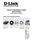
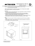
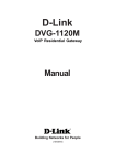
1
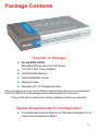
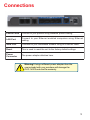
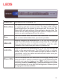
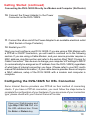
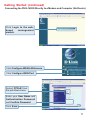
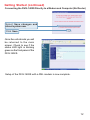
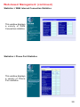
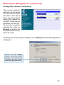
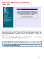
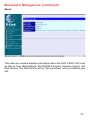
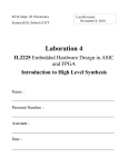
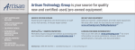
D-Link
DVG-1402S
Broadband Phone Service VoIP Router
Manual
Building Networks for People
(09/24/04)
Contents
Package Contents ................................................................................3
Introduction............................................................................................4
Connections ..........................................................................................5
Features and Benefits ...........................................................................6
LEDs ....................................................................................................7
Getting Started ......................................................................................8
Connecting the DVG-1402S Directly to a Modem and Computer ............. 8
Configuring the DVG-1402S for DSL Connection ............................... 10
Connecting the DVG-1402S in Front of a Router .................................... 13
Configuring the DVG-1402S for DSL Connection ............................... 15
Connecting the DVG-1402S Behind a Router ......................................... 18
MAC Cloning for Cable Connection .....................................................21
Web-based Management ....................................................................22
Frequently Asked Questions ................................................................44
Technical Specifications ......................................................................47
Technical Support ................................................................................50
Warranty ..............................................................................................51
2
Package Contents
Contents of Package:
D-Link DVG-1402S
Broadband Phone Service VoIP Router
12V DC/1.25A Power Adapter
CD-ROM with Manual
Quick Installation Guide
Ethernet Cable
Standard (RJ-11) Telephone Cable
Note: Using a power supply with a different voltage rating than the one included with
the DVG-1402S will cause damage and void the warranty for this product.
If any of the above items are missing, please contact your reseller.
System Requirements For Configuration:
A compter with Internet Explorer or Netscape Navigator 6.x or
above with Javascript enabled.
3
Introduction
The D-LINK DVG-1402S Broadband Phone Service VoIP Router links traditional
telephony networks to IP networks with conventional telephony devices such
as analog phones or fax machines.
The DVG-1402S includes two RJ-11 telephone jacks that provide voice
communication over the IP network, and five Ethernet ports.
One Ethernet port is for a DSL/Cable Modem or other wide area network (WAN)
devices, and the others are for connections to create a home or small office
local area network (LAN). The built-in DHCP server/client and Network Address
Translation (NAT) function automatically assign IP address for LAN users,
allowing multiple users to share a single Internet connection. It can be configured/
monitored using a Web browser.
By routing calls over the Internet or any IP network, this VoIP router can reduce
or eliminate long distance or inter-office phone charges. Corporations can also
enjoy the benefits of network consolidation and reduction of leased lines by
relying on the Internet service providers to deliver toll-quality voice
communications over the IP networks.
4
Connections
Phone Ports
Connect to your phones using standard phone cabling.
LAN Port
C o nne c t to yo ur E the rne t e na b le d c o mp ute rs us i ng E the rne t
cabling.
WAN Port
Connects to your broadband modem using an Ethernet cable.
R eset
This is used to reset the unit to the factory default settings.
P o w er
Connector
The power adapter attaches here.
Warning! Using a different power adapter than the
one included with your purchase will damage the
DVG-1402S and void the warranty.
5
Features & Benefits
Two analog RJ-11 phone connectors
One 10/100Mbps WAN port for connecting to a DSL/Cable Modem or
other WAN devices
Four 10/100Mbps LAN ports for connecting to a local network
IP address assignment using DHCP (Dynamic Host Configuration
Protocol) or static configuration
Remote software download/update
Supports IP sharing to allow multiple users to access the Internet via a
single IP address
Supports Caller ID
Supports QoS to guarantee voice quality
Optional features may be supported by your service provider such as
call waiting, caller ID, and voicemail.
6
LEDS
P o w er L E D
Status/Alarm
Indicates the unit is powered on.
The Status LED will flash when performing a self-test/booting up or
is registering with the service provider. The Status LED will flash
green slowly when the system is connected with the service. The
Alarm LED will light solid red if the self-test or bootup fails. The
Alarm LED will flash red slowly when the system is ready but cannot
receive an acknowledgement from the service.
Prov
This LED flashes when the device has established a connection
and received authorization from your service provider.
WAN LED
When a connection is established the 10 or 100 LED will light up
solid. The LED will blink to indictate activity. If the 10 or 100 LED
d o e s no t li g ht up whe n a c a b le i s c o nne c te d , ve ri fy the c a b le
connection and make sure your device is powered on.
LAN LEDs
P hone LE D s
When a connection is established the 10 or 100 LED will light up
s o li d o n the a p p ro p ri a te p o rt. The L E D s wi ll b li nk to i nd i c ta te
acti vi ty. If the 10 or 100 LED does not li ght up when a cable i s
c o nne c te d , ve ri fy the c a b le c o nne c ti o ns a nd ma k e s ure yo ur
devices are powered on.
This LED displays the VoIP status and Hook/Ringing activity on the
phone port that is used to connect to your normal telephone(s)/fax
machi ne and regular telephone li ne. MWI: Li ghts to i ndi cate a
voicemail is waiting. Hook/Ring: If a phone connected to a phone
port is off the hook or in use, this LED will light solid. When a phone
is ringing, the indicator will blink.
7
Getting Started
Connecting the DVG-1402S Directly to a
Modem and Computer
If your computer connects directly to a DSL or Cable modem and does not
connect to a router, follow the steps below to install your DVG-1402S. After the
steps are completed, your setup should look similar to the diagram below. Note:
This is the most common setup configuration for the DVG-1402S. If you do not
require the use of more than four LAN ports, you do not need an additional
router.
8
Getting Started (continued)
Connecting the DVG-1402S Directly to a Modem and Computer
1. Turn off your Computer.
2. Disconnect the power to your Cable/DSL Modem (unplug or turn off the power
switch).
3. Unplug the existing Ethernet cable that is connected to your Cable/DSL Modem’s
LAN or Ethernet port. Leave the other end of this cable attached to your PC.
4. Plug the Ethernet cable connector that you just removed from the modem into
one of the four LAN ports on the back of the DVG-1402S. The other end remains
attached to the PC.
5. Attach one end of the Ethernet Cable (blue) provided in this package to the
LAN or Ethernet Port on the Cable/DSL Modem.
6. Attach the other end of the provided Ethernet
Cable to the WAN Port of the DVG-1402S.
7. Attach one end of the provided phone cable (black) to a standard analog
telephone.
8. Attach the other end of the phone cable to the phone port labeled 1 on the
rear panel of the DVG-1402S.
9. Reconnect the power to the Cable/DSL Modem (plug in or turn on the power
switch).
9
Getting Started (continued)
Connecting the DVG-1402S Directly to a Modem and Computer (No Router)
10. Connect the Power Adapter to the Power
Connecter on the DVG-1402S.
11. Connect the other end of the Power Adapter to an available electrical outlet
(Wall Socket or Surge Protector).
12. Restart your PC.
Next you must configure your DVG-1402S. If you are using a DSL Modem with
a PPPoE or DHCP connection, you will need to continue on to the following
section. If you are using a Cable Modem, and your service provider requires a
MAC address, skip this section and refer to the section titled “MAC Cloning for
Cable Connection.” Also be sure to change your computer’s IP settings to DHCP
(to automatically be assigned an IP address from the DVG-1402S) regardless
of what type of internet connection you have. (Please refer to your NIC card’s
manual for detailed information.) If your cable service provider does not require
a MAC address, setup of the DVG-1402S with a modem and computer is
complete.
Configuring the DVG-1402S for DSL Connection
Some Internet Service providers use PPPoE as their method of connecting
clients. If you have a PPPoE connection, you must follow the steps below to
complete the configuration of your hardware. If you are unsure of your connection
type, please check with your Internet Service Provider.
Open your Web browser and
type http://192.168.15.1 into
the URL address box. Press
the Enter or Return key.
10
Getting Started (continued)
Connecting the DVG-1402S Directly to a Modem and Computer (No Router)
Click Login to the webbased
management
module.
Click Configure WAN/LAN Access.
Click Configure WAN Port.
Select PPPoE from
the pull-down menu.
Enter your User Name and
Authentication Password
and Confirm Password.
Click Save.
11
Getting Started (continued)
Connecting the DVG-1402S Directly to a Modem and Computer (No Router)
Select Save changes and
reboot system now.
Click Save.
Once the unit reboots you will
be returned to the main
screen. Check to see if the
status LED light is blinking
green on the front panel of the
DVG-1402S.
Setup of the DVG-1402S with a DSL modem is now complete.
12
Getting Started (continued)
Connecting the DVG-1402S in Front of a
Router
If you wish to connect your DVG-1402S in front of a router, follow the steps
below. After the steps are completed, your setup should look similar to the
diagram below. This is the recommended method for setting up the DVG-1402S.
This set up allows the DVG-1402S to prioritize voice traffic over data traffic,
thus providing you with greater consistency and call quality.
1. Turn off your Computer.
2. Disconnect the power to the Cable/DSL Modem (unplug or turn off the power
switch).
3. Disconnect the power to your existing router (unplug or turn off the power
switch).
4. Unplug the existing Cat 5 Ethernet cable from the “WAN” port of your existing
Router.
5. Leave the other end of this cable attached to your Cable/DSL Modem.
13
Getting Started (continued)
Connecting the DVG-1402S in Front of a Router
6. Plug the Cat 5 Ethernet Cable from the
Cable/DSL Modem into the “WAN” port of
the DVG-1402S.
7. Unpack the Cat 5 Ethernet Cable (blue) that came with the DVG-1402S.
8. Attach one end of this Cat 5 Ethernet Cable (blue) to one of the four “LAN”
Ports on the rear of the DVG-1402S.
9. Attach the other end of this Cat 5 Ethernet Cable (blue) to the “WAN” port of
your existing router.
10. Be sure that the Cat 5 Ethernet Cable that is plugged into the LAN Port of
your existing router is still plugged into your PC.
11. Unpack the Telephone Cable (black) that
came with the DVG-1402S.
12. Attach one end of this cable to a standard analog telephone.
13. Attach the other end of this cable to phone port “1” on the rear of the DVG1402S.
14. Unpack the 12V DC Power Adapter that
came with your DVG-1402S.
15. Connect the Power Adapter to the Power
Connecter on the DVG-1402S.
16. Connect the other end of the Power Adapter
to an available electrical outlet (Wall Socket
or Surge Protector).
14
Getting Started (continued)
Connecting the DVG-1402S in Front of a Router
17. Reconnect the power to the Cable/DSL Modem (plug in or turn on the power
switch).
18. Reconnect the power to your existing Router (plug in or turn on the power
switch).
19. Restart your PC.
Next you must configure your DVG-1402S and PC. If you are using a DSL
Modem with a PPPoE or DHCP connection, you will need to continue on to the
following section. If you are using a Cable Modem, and your service provider
requires a MAC address, skip this section and refer to the section titled “MAC
Cloning for Cable Connection.” Also be sure to change your computer’s IP
settings to DHCP (to automatically be assigned an IP address from the DVG1402S) regardless of what type of internet connection you have. (Please refer
to your NIC card’s manual for detailed information.) If your cable service provider
does not require a MAC address, setup of the DVG-1402S with a modem and
computer is complete.
Configuring the DVG-1402S for DSL Connection
Some Internet Service providers use PPPoE as their method of connecting
clients. If you have a PPPoE connection, you must follow the steps below to
complete the configuration of your hardware. If you are unsure of your connection
type, please check with your Internet Service Provider.
Open your Web browser and
type http://192.168.15.1 into
the URL address box. Press
the Enter or Return key.
15
Getting Started (continued)
Connecting the DVG-1402S in Front of a Router
Click Login to the webbased
management
module.
Click Configure WAN/LAN Access.
Click Configure WAN Port.
Select PPPoE from
the pull-down menu.
Enter your User Name and
Authentication Password
and Confirm Password.
Click Save.
16
Getting Started (continued)
Connecting the DVG-1402S in Front of a Router
Select Save changes and
reboot system now.
Click Save.
Once the unit reboots you will
be returned to the main
screen. Check to see if the
status LED light is blinking
green on the front panel of the
DVG-1402S.
Setup of the DVG-1402S with a DSL modem is now complete.
17
Getting Started (continued)
Connecting the DVG-1402S Behind a Router
If you wish to connect your DVG-1402S behind a router, follow the steps below.
After the steps are completed, your setup should look similar to the diagram
below.
1. Turn off your Computer.
2. Disconnect the power to the Cable/DSL Modem (unplug or turn off the power
switch).
3. Disconnect the power to your existing router (unplug or turn off the power
switch).
4. Unplug the existing Cat 5 Ethernet cable from the “LAN” port of your existing
Router.
5. Leave the other end of this cable attached to your PC.
18
Getting Started (continued)
Connecting the DVG-1402S Behind a Router
6. Plug the Cat 5 Ethernet Cable from the PC
into the “LAN” port of the DVG-1402S.
7. Unpack the Cat 5 Ethernet Cable (blue) that came with the DVG-1402S.
8. Attach one end of this Cat 5 Ethernet Cable (blue) to the “WAN” Port on the
rear of the DVG-1402S.
9. Attach the other end of this Cat 5 Ethernet Cable (blue) to the “LAN” port of
your existing router.
10. Be sure that the Cat 5 Ethernet Cable that is plugged into the “WAN” Port of
your existing router is still plugged into your Cable/DSL Modem.
11. Unpack the Telephone Cable (black) that came with the DVG-1402S.
12. Attach one end of this cable to a standard analog telephone.
13. Attach the other end of this cable to phone
port “1” on the rear of the DVG-1402S.
14. Unpack the 12V DC Power Adapter that came with your DVG-1402S.
15. Connect the Power Adapter to the Power
Connecter on the DVG-1402S.
19
Getting Started (continued)
Connecting the DVG-1402S Behind a Router
16. Connect the other end of the Power Adapter to an available electrical outlet
(Wall Socket or Surge Protector).
17. Reconnect the power to the Cable/DSL Modem (plug in or turn on the power
switch).
18. Reconnect the power to your existing Router (plug in or turn on the power
switch).
19. Restart your PC.
By default the unit is already configured to work behind a router. Be sure to
change your computer’s IP settings to DHCP (to automatically be assigned an
IP address from the DVG-1402S) regardless of what type of internet connection
you have. (Please refer to your NIC card’s manual for detailed information.)
Installation behind a router is now complete.
20
MAC Cloning For Cable Connection
Some cable Internet service providers require that device connected to the
cable modem has the MAC address of the PC that was originally registered
with the cable Internet provider. If this is required to set up the DVG-1402S,
follow the steps below.
1. On the computer that was originally registered with your service provider.
For Windows 98/Me users: Go to Start > Run > command. Type in ipconfig/
all. The physical address listed is your system’s MAC address.
For Windows 2000/XP users: Go to Start> Run > cmd. Type in ipconfig/
all. The physical address listed is your system’s MAC address.
For Mac users: Click the Apple icon in the upper left hand corner of the
screen. Go to System Preferences > Network and click on the network
device you use to connect to the Internet. Click the Ethernet button. The
ethernet ID listed is your system’s MAC address.
2. Write down the MAC address of your system. This address is written in the
following format: 00:aa:bb:11:22:33.
3. Open a Web browser and type in the IP address of the DVG-1402S (default
is 192.168.15.1). Log into the Web-based management module (see the
next section for more information) and click on Configure WAN Port. The
following page will appear.
4. Select DHCP from the connection type pull down menu.
5. In the MAC Cloning field, enter your system’s MAC address (from step 2).
6. Click the Save button to save your settings.
7. Mac Cloning configuration is now complete.
21
Web-based Management
Prior to using your Web browser for Web-based management, if DHCP is not
enabled on your computer, be sure to assign a static IP address to the VoIP
Router.
Go to Start>Control
Panel>Network
Connections>Right-click local
area connection >select
Properties> double click Internet
Protocol (TCP/IP). The screen at
right will appear.
The VoIP Router’s LAN port comes
with DHCP as default IP setting. If the
VoIP gateway cannot get the
assigned DHCP IP, it will use the
manual IP (default is 192.168.15.1 )
as it’s default IP.
192 . 168 . 15 . 15
255 . 255 . 255 . 0
Set your PC’s IP address to
192.168.15.15 and the subnet mask
to 255.255.255.0.
In order to use a Web browser to configure the VoIP Router you must make
sure it has a valid Ethernet connection to a PC or LAN via its LAN port.
Access the configuration utility to check the LAN port by entering the IP Address
into your web browser address field.
Type 192.168.15.1
(the IP Address) into
the address field of
your browser.
22
Web-based Management (continued)
Click on Login to the
Web-based
Management
module
Setting Up the Connection
To configure the WAN port, please do the following:
Click on Configure WAN Port.
Choose your type of connection.
Manually enter your DNS address
(if applicable).
23
Web-based Management (continued)
To configure the LAN port for the device, please do
the following:
Click on Configure LAN Port.
In this configuration menu, users can configure the LAN IP Address.
(Recommended for advanced users.)
By default the LAN IP Address is: 192.168.15.1
After you have configured your WAN and LAN ports you can click on Save and
Restart System in the Configuration menu, or you can continue to configure
the VoIP Router. After you have completed configuring the VoIP Router, you
must Save and Restart the System or your changes will not be saved.
24
Web-based Management (continued)
Configure LAN Port > Proxy DNS
State - This toggles
Enable and Disable for
the
Proxy
DNS
function.
Proxy
DNS
IP
Address - Enter the
Proxy DNS IP address
if instructed by your
service provider.
Click Save to save the settings.
Configure LAN Port > Bridge Mode
Bridge Mode - This
toggles On and Off to
turn NAT on or off for
Static Public IP
assignment.
Click Save to save the settings.
25
Web-based Management (continued)
Configure LAN Port > DHCP Configuration > Dynamic IP Assignment
Use the Dynamic IP
Assignment
to
configure the device to
act as a DHCP server
for the LAN.
The items on this
window are described
below:
Default Gateway - This specifies the Gateway IP Address that will be assigned
to and used by the DHCP clients.
Start IP Address -This is the base (starting) address for the IP pool of
unassigned IP addresses.
IP Range - This is the range of contiguous, IP addresses above the base IP
Address above.
Netmask - This mask informs the client, how the destination IP address is to
be divided into network, subnet, and host parts. The netmask has ones in the
bit positions in the 32-bit address which are to be used for the network and
subnet parts, and zeros for the host part.
Leased Time - This specifies the amount of time (in seconds) a client can
lease an IP address, from the dynamically allocated IP pool.
DNS Server IP - This specifies the Domain Name System server, used by the
DHCP clients using leased IP addresses, to translate hostnames into IP
addresses or vice-versa.
WIN Server IP - Some LANs may require using WINS servers; enter the IP
address of the WINS server or leave blank.
Domain Name - Enter a domain name for the network group or leave blank.
State - This toggles Disable and Enable for the DHCP function.
Click Save to save the settings.
26
Web-based Management (continued)
Configure LAN Port > DHCP Configuration > Static IP Assignment
The
Static
IP
Assignment functions
in much the same way
as the Dynamic IP
Assignment. The only
difference is that a
particular IP address
can be assigned to a
particular host. The
host is identified by the
MAC Address of its NIC
which must be entered
on next screen.
Click the edit icon on the window above to access the second Static IP
Assignment window:
The items on this
window are described
below:
Index - Choose the
index number that you
would like to edit (From
1 to 4).
MAC Address - This
specifies the physical
address
of
the
particular host that will
receive the below IP address.
IP Address - This is the static IP address to be assigned.
All other parameters (Netmask, Gateway, DNS Server IP, WINS Server IP,
Domain Name and State) are identical to those in the Dynamic IP Assignment,
in the previous section.
Click Save to save the settings.
27
Web-based Management (continued)
Configure LAN Port > NAT Configuration
Select enabled or
disabled for the NAT
function.
Click Save to save the
settings.
Configure LAN Port > NAT Configuration > Virtual Server Configuration
This window allows
you to view the current
virtual server
configuration settings.
Click the edit icon on this window to access the second Virtual Server
Configuration window:
28
Web-based Management (continued)
Configure LAN Port > NAT Configuration > Virtual Server Configuration
(continued)
The items on this
window are described
below:
Index - Choose the
index number that you
would like to edit (Form
1 to 6).
Protocol - Choose the
protocol either TCP or
UDP.
Global Port Range Enter the designated TCP or UDP protocol port number for the particular
protocol packet you wish to redirect.
Local Port Range - Enter the port number used by the designated host on the
LAN or use a well-known port.
Server IP - Enter the IP address of the local designated host computer or
device.
State - This toggles Disable and Enable for the Virtual Server Configuration
function.
Click Save to save the settings.
29
Web-based Management (continued)
Configure LAN Port > NAT Configuration > Virtual Server Configuration
(continued)
The items on this
window are described
below:
DMZ Forwarding
Mode - Select to
enable or disable the
DMZ. The DMZ
(Demilitarized Zone)
allows
a
single
computer to be
exposed
to
the
internet. By default the
DMZ is disabled.
DMZ Host IP Address - Enter the IP address of the DMZ host.
Click Save to save the settings.
Configure LAN Port > NAT Configuration > Dynamic NAT
This window allows you to
view the current Dynamic
NAT settings.
Click the edit icon on
this window to access
the second Dynamic
NAT window:
30
Web-based Management (continued)
Configure LAN Port > NAT Configuration > Dynamic NAT (continued)
The items on this
window are described
below:
Index - Choose the
index number that you
would like to edit (Form
1 to 6).
Global IP Start Enter the beginning
designated IP address
for the particular range
of packets you wish to
redirect to local
addresses.
Global IP End - Enter the end designated IP address for the particular range of
packets you wish to redirect to local addresses.
Local IP Start - Enter the beginning designated IP address for the particular
range of packets you wish to redirect to Global addresses.
Local IP End - Enter the end designated IP address for the particular range of
packets you wish to redirect to Global addresses.
State - This toggles Disable and Enable for the Dynamic NAT function.
Click Save to save the settings.
31
Web-based Management (continued)
Configure LAN Port > NAT Configuration > Static NAT
This window allows you
to view the current Static
NAT settings.
Click the edit icon on
this window to access
the second Static NAT
window:
The items on this
window are described
below:
Index - Choose the index number that you would like to edit (Form 1 to 6).
Local IP Address - Enter the designated IP address for the packet you wish to
redirect to a Global address.
Global IP Address - Enter the designated IP address for the packet you wish
to redirect to a Local address.
State - This toggles Disable and Enable for the Static NAT function for this
index.
Click Save to save the settings.
32
Web-based Management (continued)
Configure LAN Port > Routing > RIP
Select to use RIPv1,
RIPv2 or On (both
versions) for the LAN
and WAN interface.
To disable both
versions of RIP
select Off.
Click Save to save
the settings.
RIP - Routing
Information Protocol
that specifies how
routers exchange
information. With RIP,
routers periodically
exchange entire tables.
Configure LAN Port > Routing > Static Route Configuration
Use Static Routing to
specify a route used
for data traffic within
your WAN or LAN.
This can be used to
specify that all
packets destined for
a particular subnet
use a predetermined
gateway.
Click the edit icon on
the window above to
access the second
Static Route
Configuration
window:
33
Web-based Management (continued)
Configure LAN Port > RIP > Static Route Configuration (continued)
The items on this
window are described
below:
IP Address - Type in the IP Address of the subnet or device where packets are
routed.
Subnet Mask - Type in an appropriate subnet mask that allows the static
route to function.
Gateway - Type in the IP Address of the gateway used for traffic destined for
the specified subnet or device.
Interface - Select WAN or LAN Interface.
Metric - Type in the maximum number of hops allowed for the static route.
State - Enable or disable the route.
Click Save or Clear to Save or Clear the settings.
34
Web-based Management (continued)
Firewall Rules
Firewall Rules is an
advance feature used
to deny or allow traffic
from passing through
the device. The filtering
sets are sets of rules
defined in the menus
shown below.
Click the edit icon on
the window above to
access the Firewall
Rules window for the
first rules set:
Type in an appropriate
identifying comment for
the Firewall Rules set.
When you are finished
defining the rules for
each set, select
enabled or disabled
to enable or disable the
listed Firewall rules
sets.
Click Save button to
save the settings.
Click the edit icon on the window above to access the third IP Filter window,
shown on the following page:
35
Web-based Management (continued)
Firewall Rules (continued)
Comment- Type in an
appropriate identifying
comment for the rule.
Pass or BlockSelect Pass or Block
to perform this action
on packets as defined
below.
Direction- Select In
or Out to pass or
block packets coming
in or going out of the
network.
Protocol- Select IGMP, TCP, UDP or All to pass or block packets of that
protocol type.
Source- Type in the source IP Address and select the Subnet Mask to pass
or block packets from that IP Address.
Destination- Type in the destination IP Address and select the Subnet Mask
to pass or block packets destined to that IP Address.
Port Filter Rule- UDP and TCP packets only. Select a range of ports to
pass or block. Use the following guide to define the port or port range (Start
Port and End Port):
< : specifies the port numbers less than and equal to the Start Port
number
> : specifies the port numbers greater than and equal to the Start Port
number
= : sets the port number equal to the Start Port if there is no End Port
specified; if an End Port number is specified, this defines a range of
ports to filter. The range is defined as the port numbers between the Start
Port and End Port, including the Start and End Port numbers.
≠ : the port number does not equal the Start Port if there is no End Port
specified; if an End Port number is specified, this defines a range of
ports not to filter. The range is defined as the port numbers between
the Start Port and End Port, including the Start and End Port numbers.
36
Web-based Management (continued)
Firewall Rules (continued)
TCP Flag - Select enabled or disabled to enable or disable the filter rule as
defined in the menu.
TCP Packet Options - Optional TCP packet options include: Acknowledgment,
Push, Reset, SYN, and FIN. Consult a certified technician before selecting any
of these advanced options.
Filter Rule State - Select enabled or disabled to enable or disable the filter
rule as defined in the menu.
Click Save or click Clear to Save or Clear the settings.
MAC Filter
MAC (Media Access
Control) Filters are
used to deny or allow
LAN (Local Area
Network)
computers from
accessing the Internet
and network by their
MAC address.
Click the edit icon on the window above to access the MAC Filter window,
shown on the following page:
37
Web-based Management (continued)
MAC Filter (continued)
The items on this
window are described
below:
Index - This is the
index number that you
are editing (1-16).
MAC Address - Enter
the MAC address of the
client that will be
filtered.
State - This toggles Disable and Enable for the MAC address filtering function
for this index.
Click the Save button to save the settings.
Configure Pass Through Mode
The device supports VPN
(Virtual Private Network)
pass-through for both
PPTP (Point-to-Point
Tunneling Protocol),
IPSec (IP Security), and
L2TP (Layer 2 Tunneling
Protocol). Once VPN
pass-through is enabled,
there is no need to open
up virtual services.
Multiple VPN connections
can be made through the
device. This is useful
when you have many VPN
clients on the LAN.
PPTP Pass Through / IPSec Pass Through / L2TP Pass Through - This
toggles Disable and Enable for the Pass Through function.
Click the Save button to save the settings.
38
Web-based Management (continued)
Statistics > WAN Internet Connection Statistics
This window displays
a variety of WAN
Connection statistics.
Statistics > Phone Port Statistics
This window displays
a variety of Phone
Port statistics.
39
Web-based Management (continued)
Configuration Restore and Backup
The current system
settings can be saved
as a file onto the local
hard drive. The saved
file or any other saved
setting file created by
the DVG-1402S can be
uploaded into the unit.
To restore a system
settings file, click on
Browse to search the
local hard drive for the
file to be used.
To backup the current system settings, click on Backup and the following window
will appear:
Click on the Save
button and select the
location on your hard
drive to save the file to.
40
Web-based Management (continued)
Factory Reset
Before performing a Factory Reset, be absolutely certain that this is what you
want to do. Once the reset is done, all of the device’s settings stored in NVRAM will be erased and restored to values present when the device was
purchased.
Click on Reset to Factory Default to reset the NV-RAM to the default values
that were present when you purchased the device.
Note: After performing the Factory Reset, make sure to redefine the IP
settings for the device in the IP Configuration menu. Then perform a
Restart System on the device. After these three procedures are performed,
your Factory Reset is complete.
41
Web-based Management (continued)
Save and Restart System
After the settings have been saved to NV-RAM, they will become the default
settings for the device, and they will be used every time it is powered on, reset
or rebooted. The only exception to this is a factory reset, which will clear all
settings and restore the unit’s settings back to their initial values, which were
present when the device was purchased.
Click on Save Configuration at the bottom of the window to save the system
settings to NV-RAM.
Advanced
This section contains advanced configuration settings for the DVG-1402S VoIP
Router. Please consult a certified technician before making any changes to the
Advanced menu.
42
Web-based Management (continued)
About
This read-only window displays information about the DVG-1402S VoIP such
as: Device Type, MAC Address, Boot PROM Firmware, Firmware Version, and
DSP Version. The DSP Version will list “Not yet loaded” until you initialize your
unit.
43
Frequently Asked Questions
Q: I have completed the installation of my D-Link DVG-1402S, but do not hear
a dial tone.
A: Be sure that the unit is properly plugged into the AC outlet, the analog phone
is properly plugged into the RJ11 jack behind the unit, and the power connector
is plugged in. Verify that status lights are lit/blinking.
1) Verify the Power light is on.
2) Initially the Alarm light will blink.
3) The provision (prov.) Light will also blink during the boot up.
4) When Provisioning is complete, the Status light will blink continuously.
5) Verify that the WAN light is lit along with the corresponding LAN port light
and that the PC is plugged into on the back of the DVG-1402S. At this
point, the “Power” light, “Status” light, “WAN” light, and “LAN” light (if the
PC or another device is plugged in to the LAN port) should be lit green.
A: Confirm that your service has been activated by your VoIP service provider.
Q: I get a dial tone, but when I dial any phone number I receive a busy signal.
A: The unit may not have been properly configured with the correct account
information in the Web GUI utility.
1) Access the Web GUI by entering the IP address: 192.168.15.1 in the
Address bar.
2) Select the Advanced setting link.
3) Select SIP Configuration.
4) In the Server link, enter the correct information (server address, Port
Number, Outbound Proxy server info [if applicable], Domain Name [if
applicable], etc.)
5) Select User Agent link and enter the account information provided by
your VoIP service provider, i.e. Phone Number, Display name, User agent
44
Frequently Asked Questions (continued)
port, Authentication User Name, Authentication Password, and Confirm
Password.
Q: After setting up the DVG-1402S, I cannot surf the internet.
A: Re-check all the cabling installations. Make sure that the Ethernet cable
from the PC is plugged into one of the LAN ports of the DVG-1402S and the
Ethernet cable from the cable modem is plugged into the WAN port of the DVG1402S. Once this is verified but you still cannot access the Internet, then verify
the configurations via the Web GUI.
1) Access the Web GUI by entering the IP address: 192.168.15.1 in the
Address bar.
2) Select Configure WAN/LAN Access.
3) Select Configure WAN Port.
4) In the WAN Restart settings – Get IP from one of the following:
a. If using a cable modem - Choose DHCP and fill in the available
information and click “Save”. User will be prompted to either
“Save changes and reboot system now” or “Continue and
‘Restart System’ later”. Choose “Save changes and reboot
system now” and wait for the unit to reboot (not the PC).
b. If using a DSL modem – Choose PPPoE and fill in the available
information and click “Save”. User will be prompted to either
“Save changes and reboot system now” or “Continue and
‘Restart System’ later”. Choose “Save changes and reboot
system now” and wait for the unit to reboot (not the PC).
c. If the service provider gives a specific IP address – Choose
Manual and enter the given information in the fields.
5) Once the DVG-1420S has rebooted, select Configure LAN Port.
6) Select Dynamic IP assignment.
7) In the “State” field, make sure that “Enabled” is selected.
8) Select “Save” and choose to reboot the DVG-1402S (not the PC).
9) Verify that the IP address on the PC has an address of 192.168.15.x ,
where “x” is a number assigned by the DVG-1420S.
45
Frequently Asked Questions (continued)
10) Verify that the WAN port for Public IP is NOT 10.1.1.1. (It must be an IP
address given by your Internet Service Provider (ISP) through the Cable or
DSL modem.)
Q: Can I use my DVG-1402S on a MGCP network?
A: No, DVG-1402S is a SIP device and uses the SIP protocol in handling all of
the telephony elements.
Q: I need to open certain ports, where do I go to make this configuration change?
A: This can be done in the “Firewall Rules”.
1) Select Firewall Rules in the Web GUI menu.
2) Select “Edit” in Set# 1.
3) In line # 1, select “Edit.”
4) Make the necessary modifications on this screen.
5) Be sure to select “Enable” in the Firewall Rule State drop down menu.
6) Click “Save”.
a. Click “Exit.”
b. If you are entering more than 1 rule, click “Edit” in the next line
and repeat the previous steps. If not, Click “Exit” again on the
lower left side.
7) If no more changes need to be made, click “Save Changes and Reboot.”
46
Technical Specifications
Call Control Protocols Compliance:
SIP2 (RFC3261)
SIP1 (RFC2543)
Voice Compression:
G.711 (A-law and u-law), G.723.1, G.726, G.729a
Analog Voice Ports:
Type: Loop-Start FXS interfaces
DTMF tone detection/generation
V.21/V.25 Modem/Fax tone detection
Echo Cancellation: G.168
Ethernet Ports:
WAN/LAN: 10/100 Auto MDI/MDI-X Ethernet ports
IEEE 802.3 10BASE-T Ethernet compliance
IEEE 802.3u 100BASE-TX Fast Ethernet compliant
Quality of Service:
Voice service is prioritized over the data traffic
(When unit is connected directly to the modem)
Network Protocols:
Will route all standard protocols
DHCP: Dynamic Host Configuration Protocol server and client
NAT: Network Address Translation
PPP over Ethernet Client
Network Management:
Manage functions through an intuitive Web-based graphical
user interface
47
Technical Specifications (continued)
LEDs:
General:
Power
Status/Alarm
Ethernet:
WAN: 10/100M, Link/Act
LAN: 10/100M, Link/Act
Phone 1 to 2:
MWI
Hook/Ringing
Provision Light
Dimensions:
W = 6.77 inches (172mm)
D = 6.16 inches (156.6 mm)
H = 1.34 inches (34mm)
Number of Ports:
One 10/100BASE-T Ethernet port (WAN)
Four 10/100BASE-TX Fast Ethernet port (LAN)
Two loop-start FXS RJ-11 ports
Power Supply:
AC-to-DC power adapter (provided)
DC Input: 12VDC/1.2A
Operating Temperature:
0-50°C
Storage Temperature:
-10-55°C
Humidity:
5% - 95% non-condensing
48
Technical Specifications (continued)
Safety:
UL/CUL
Emission (EMI):
FCC Class B
CE Class B
49
For Technical Support regarding
your phone service, please contact
the service provider.
If you experience any hardware problems with the DVG-1402S, please
contact D-Link Technical Support.
Techni
cal Support
echnical
You can find software updates and user documentation on the D-Link website.
D-Link provides free technical support for customers within the United States and
within Canada for the duration of the warranty period on this product.
U.S. and Canadian customers can contact D-Link technical support through our
website, or by phone.
Tech Support for customers within the United States:
D-Link Technical Support over the Telephone:
(877) 453-5465
24 hours a day, seven days a week.
D-Link Technical Support over the Internet:
http://support.dlink.com
email:[email protected]
Tech Support for customers within Canada:
D-Link Technical Support over the Telephone:
(800) 361-5265
Monday to Friday 7:30am to 12:00am EST
D-Link Technical Support over the Internet:
http://support.dlink.ca
email:[email protected]
50
Warranty and Registration
Subject to the terms and conditions set forth herein, D-Link Systems, Inc. (“D-Link”) provides this Limited
warranty for its product only to the person or entity that originally purchased the product from:
D-Link or its authorized reseller or distributor and
Products purchased and delivered within the fifty states of the United States, the District of
Columbia, U.S. Possessions or Protectorates, U.S. Military Installations, addresses with an
APO or FPO.
Limited Warranty: D-Link warrants that the hardware portion of the D-Link products described
below will be free from material defects in workmanship and materials from the date of original retail
purchase of the product, for the period set forth below applicable to the product type (“Warranty
Period”), except as otherwise stated herein.
1-Year Limited Warranty for the Product(s) is defined as follows:
Hardware (excluding power supplies and fans) One (1) Year
Power Supplies and Fans One (1) Year
Spare parts and spare kits Ninety (90) days
D-Link’s sole obligation shall be to repair or replace the defective Hardware during the Warranty Period
at no charge to the original owner or to refund at D-Link’s sole discretion. Such repair or replacement will
be rendered by D-Link at an Authorized D-Link Service Office. The replacement Hardware need not be
new or have an identical make, model or part. D-Link may in its sole discretion replace the defective
Hardware (or any part thereof) with any reconditioned product that D-Link reasonably determines is
substantially equivalent (or superior) in all material respects to the defective Hardware. Repaired or
replacement Hardware will be warranted for the remainder of the original Warranty Period from the date
of original retail purchase. If a material defect is incapable of correction, or if D-Link determines in its sole
discretion that it is not practical to repair or replace the defective Hardware, the price paid by the original
purchaser for the defective Hardware will be refunded by D-Link upon return to D-Link of the defective
Hardware. All Hardware (or part thereof) that is replaced by D-Link, or for which the purchase price is
refunded, shall become the property of D-Link upon replacement or refund.
Limited Software Warranty: D-Link warrants that the software portion of the product (“Software”)
will substantially conform to D-Link’s then current functional specifications for the Software, as set forth
in the applicable documentation, from the date of original retail purchase of the Software for a period of
ninety (90) days (“Warranty Period”), provided that the Software is properly installed on approved
hardware and operated as contemplated in its documentation. D-Link further warrants that, during the
Warranty Period, the magnetic media on which D-Link delivers the Software will be free of physical
defects. D-Link’s sole obligation shall be to replace the non-conforming Software (or defective media)
with software that substantially conforms to D-Link’s functional specifications for the Software or to
refund at D-Link’s sole discretion. Except as otherwise agreed by D-Link in writing, the replacement
Software is provided only to the original licensee, and is subject to the terms and conditions of the
license granted by D-Link for the Software. Software will be warranted for the remainder of the original
Warranty Period from the date or original retail purchase. If a material non-conformance is incapable of
correction, or if D-Link determines in its sole discretion that it is not practical to replace the nonconforming Software, the price paid by the original licensee for the non-conforming Software will be
refunded by D-Link; provided that the non-conforming Software (and all copies thereof) is first returned
to D-Link. The license granted respecting any Software for which a refund is given automatically
terminates.
Non-Applicability of Warranty: The Limited Warranty provided hereunder for hardware and software
of D-Link’s products will not be applied to and does not cover any refurbished product and any product
purchased through the inventory clearance or liquidation sale or other sales in which D-Link, the sellers,
or the liquidators expressly disclaim their warranty obligation pertaining to the product and in that case,
the product is being sold “As-Is” without any warranty whatsoever including, without limitation, the
Limited Warranty as described herein, notwithstanding anything stated herein to the contrary.
Submitting A Claim: The customer shall return the product to the original purchase point based on its
return policy. In case the return policy period has expired and the product is within warranty, the
customer shall submit a claim to D-Link as outlined below:
The customer must submit with the product as part of the claim a written description of the
Hardware defect or Software nonconformance in sufficient detail to allow D-Link to confirm
the same.
51
The original product owner must obtain a Return Material Authorization (“RMA”) number from
the Authorized D-Link Service Office and, if requested, provide written proof of purchase of
the product (such as a copy of the dated purchase invoice for the product) before the
warranty service is provided.
After an RMA number is issued, the defective product must be packaged securely in the
original or other suitable shipping package to ensure that it will not be damaged in transit, and
the RMA number must be prominently marked on the outside of the package. Do not include any
manuals or accessories in the shipping package. D-Link will only replace the defective portion
of the Product and will not ship back any accessories.
The customer is responsible for all in-bound shipping charges to D-Link. No Cash on Delivery
(“COD”) is allowed. Products sent COD will either be rejected by D-Link or become the
property of D-Link. Products shall be fully insured by the customer and shipped to D-Link
Systems, Inc., 17595 Mt. Herrmann St., Fountain Valley, CA 92708. D-Link will not be
held responsible for any packages that are lost in transit to D-Link. The repaired or replaced
packages will be shipped to the customer via UPS Ground or any common carrier selected by
D-Link, with shipping charges prepaid. Expedited shipping is available if shipping charges are
prepaid by the customer and upon request.
D-Link may reject or return any product that is not packaged and shipped in strict compliance with the
foregoing requirements, or for which an RMA number is not visible from the outside of the package. The
product owner agrees to pay D-Link’s reasonable handling and return shipping charges for any product
that is not packaged and shipped in accordance with the foregoing requirements, or that is determined
by D-Link not to be defective or non-conforming.
What Is Not Covered: This limited warranty provided by D-Link does not cover: Products, if in D-Link’s
judgment, have been subjected to abuse, accident, alteration, modification, tampering, negligence, misuse,
faulty installation, lack of reasonable care, repair or service in any way that is not contemplated in the
documentation for the product, or if the model or serial number has been altered, tampered with, defaced
or removed; Initial installation, installation and removal of the product for repair, and shipping costs;
Operational adjustments covered in the operating manual for the product, and normal maintenance;
Damage that occurs in shipment, due to act of God, failures due to power surge, and cosmetic damage;
Any hardware, software, firmware or other products or services provided by anyone other than DLink; Products that have been purchased from inventory clearance or liquidation sales or other sales in
which D-Link, the sellers, or the liquidators expressly disclaim their warranty obligation pertaining to the
product. Repair by anyone other than D-Link or an Authorized D-Link Service Office will void this
Warranty.
Disclaimer of Other Warranties: EXCEPT FOR THE LIMITED WARRANTY SPECIFIED HEREIN, THE
PRODUCT IS PROVIDED “AS-IS” WITHOUT ANY WARRANTY OF ANY KIND WHATSOEVER INCLUDING,
WITHOUT LIMITATION, ANY WARRANTY OF MERCHANTABILITY, FITNESS FOR A PARTICULAR PURPOSE
AND NON-INFRINGEMENT. IF ANY IMPLIED WARRANTY CANNOT BE DISCLAIMED IN ANY TERRITORY
WHERE A PRODUCT IS SOLD, THE DURATION OF SUCH IMPLIED WARRANTY SHALL BE LIMITED TO
NINETY (90) DAYS. EXCEPT AS EXPRESSLY COVERED UNDER THE LIMITED WARRANTY PROVIDED
HEREIN, THE ENTIRE RISK AS TO THE QUALITY, SELECTION AND PERFORMANCE OF THE PRODUCT IS
WITH THE PURCHASER OF THE PRODUCT.
Limitation of Liability: TO THE MAXIMUM EXTENT PERMITTED BY LAW, D-LINK IS NOT LIABLE
UNDER ANY CONTRACT, NEGLIGENCE, STRICT LIABILITY OR OTHER LEGAL OR EQUITABLE THEORY
FOR ANY LOSS OF USE OF THE PRODUCT, INCONVENIENCE OR DAMAGES OF ANY CHARACTER,
WHETHER DIRECT, SPECIAL, INCIDENTAL OR CONSEQUENTIAL (INCLUDING, BUT NOT LIMITED TO,
DAMAGES FOR LOSS OF GOODWILL, LOSS OF REVENUE OR PROFIT, WORK STOPPAGE, COMPUTER
FAILURE OR MALFUNCTION, FAILURE OF OTHER EQUIPMENT OR COMPUTER PROGRAMS TO WHICH DLINK’S PRODUCT IS CONNECTED WITH, LOSS OF INFORMATION OR DATA CONTAINED IN, STORED ON,
OR INTEGRATED WITH ANY PRODUCT RETURNED TO D-LINK FOR WARRANTY SERVICE) RESULTING
FROM THE USE OF THE PRODUCT, RELATING TO WARRANTY SERVICE, OR ARISING OUT OF ANY
BREACH OF THIS LIMITED WARRANTY, EVEN IF D-LINK HAS BEEN ADVISED OF THE POSSIBILITY OF
SUCH DAMAGES. THE SOLE REMEDY FOR A BREACH OF THE FOREGOING LIMITED WARRANTY IS
REPAIR, REPLACEMENT OR REFUND OF THE DEFECTIVE OR NON-CONFORMING PRODUCT. THE MAXIMUM
LIABILITY OF D-LINK UNDER THIS WARRANTY IS LIMITED TO THE PURCHASE PRICE OF THE PRODUCT
COVERED BY THE WARRANTY. THE FOREGOING EXPRESS WRITTEN WARRANTIES AND REMEDIES
ARE EXCLUSIVE AND ARE IN LIEU OF ANY OTHER WARRANTIES OR REMEDIES, EXPRESS, IMPLIED OR
STATUTORY
52
Governing Law: This Limited Warranty shall be governed by the laws of the State of California. Some
states do not allow exclusion or limitation of incidental or consequential damages, or limitations on how
long an implied warranty lasts, so the foregoing limitations and exclusions may not apply. This limited
warranty provides specific legal rights and the product owner may also have other rights which vary
from state to state.
Trademarks: D-Link is a registered trademark of D-Link Systems, Inc. Other trademarks or registered
trademarks are the property of their respective manufacturers or owners.
Copyright Statement: No part of this publication or documentation accompanying this Product may
be reproduced in any form or by any means or used to make any derivative such as translation,
transformation, or adaptation without permission from D-Link Corporation/D-Link Systems, Inc., as
stipulated by the United States Copyright Act of 1976. Contents are subject to change without prior
notice. Copyright© 2002 by D-Link Corporation/D-Link Systems, Inc. All rights reserved.
CE Mark Warning: This is a Class B product. In a domestic environment, this product may cause radio
interference, in which case the user may be required to take adequate measures.
FCC Statement: This equipment has been tested and found to comply with the limits for a Class B
digital device, pursuant to part 15 of the FCC Rules. These limits are designed to provide reasonable
protection against harmful interference in a residential installation. This equipment generates, uses, and
can radiate radio frequency energy and, if not installed and used in accordance with the instructions,
may cause harmful interference to radio communication. However, there is no guarantee that interference
will not occur in a particular installation. If this equipment does cause harmful interference to radio or
television reception, which can be determined by turning the equipment off and on, the user is encouraged
to try to correct the interference by one or more of the following measures:
Reorient or relocate the receiving antenna.
Increase the separation between the equipment and receiver.
Connect the equipment into an outlet on a circuit different from that to which the receiver is
connected.
Consult the dealer or an experienced radio/TV technician for help.
FCC Caution:
The manufacturer is not responsible for any radio or TV interference caused by unauthorized
modifications to this equipment; such modifications could void the user’s authority to operate the
equipment.
This device complies with Part 15 of the FCC Rules. Operation is subject to the following two
conditions: (1) This device may not cause harmful interference, and (2) this device must accept
any interference received, including interference that may cause undesired operation.
IMPORTANT NOTE:
FCC Radiation Exposure Statement:
This equipment complies with FCC radiation exposure limits set forth for an uncontrolled
environment.
Register online your D-Link product at http://support.dlink.com/register/
09/24/04
53