1
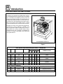
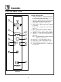
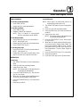
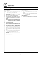
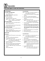
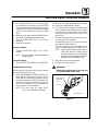
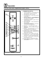
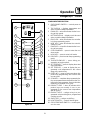
MARK V XCEL
CONVECTION OVEN
INSTALLATION -- OPERATION -- MAINTENANCE
BLODGETT OVEN COMPANY
www.blodgett.com
44 Lakeside Avenue, Burlington, Vermont 05401 USA Telephone (800) 331-5842, (802) 860-3700 Fax: (802)864-0183
PN 36433 Rev C (2/05)
E 2003 --- G.S. Blodgett Corporation
IMPORTANT
WARNING: IMPROPER INSTALLATION, ADJUSTMENT,
ALTERATION, SERVICE OR MAINTENANCE CAN CAUSE
PROPERTY DAMAGE, INJURY OR DEATH. READ THE INSTALLATION, OPERATING AND MAINTENANCE INSTRUCTIONS THOROUGHLY BEFORE INSTALLING OR
SERVICING THIS EQUIPMENT
FOR YOUR SAFETY
Do not store or use gasoline or other flammable vapors or
liquids in the vicinity of this or any other appliance.
The information contained in this manual is important for the proper
installation, use, and maintenance of this oven. Adherence to these
procedures and instructions will result in satisfactory baking results
and long, trouble free service. Please read this manual carefully and
retain it for future reference.
Errors: Descriptive, typographic or pictorial errors are subject to correction. Specifications are subject to change without notice.
THE REPUTATION YOU CAN COUNT ON
For over a century and a half, The Blodgett Oven Company has been building
ovens and nothing but ovens. We’ve set the industry’s quality standard for all
kinds of ovens for every foodservice operation regardless of size, application
or budget. In fact, no one offers more models, sizes, and oven applications
than Blodgett; gas and electric, full-size, half-size, countertop and deck, convection, Cook’n Hold, Combi-Ovens and the industry’s highest quality Pizza
Oven line. For more information on the full line of Blodgett ovens contact your
Blodgett representative.
Model:
Your Service Agency’s Address:
Serial Number:
Your oven was installed by:
Your oven’s installation was checked by:
Table of Contents
Introduction
Oven Description and Specifications . . . . . . . . . . . . . . . . . . . . . . . . . . . . . . . .
2
Installation
Delivery and Location . . . . . . . . . . . . . . . . . . . . . . . . . . . . . . . . . . . . . . . . . . . . .
Oven Assembly . . . . . . . . . . . . . . . . . . . . . . . . . . . . . . . . . . . . . . . . . . . . . . . . . .
Sanitation Bolts . . . . . . . . . . . . . . . . . . . . . . . . . . . . . . . . . . . . . . . . . . . . . . .
Leg Attachment . . . . . . . . . . . . . . . . . . . . . . . . . . . . . . . . . . . . . . . . . . . . . . .
Caster Assembly . . . . . . . . . . . . . . . . . . . . . . . . . . . . . . . . . . . . . . . . . . . . . .
Double Section Assembly . . . . . . . . . . . . . . . . . . . . . . . . . . . . . . . . . . . . . .
Oven Leveling . . . . . . . . . . . . . . . . . . . . . . . . . . . . . . . . . . . . . . . . . . . . . . . .
Utility Connections --- Standards and Codes . . . . . . . . . . . . . . . . . . . . . . . . .
Electrical Connection . . . . . . . . . . . . . . . . . . . . . . . . . . . . . . . . . . . . . . . . . . . . .
Initial Startup . . . . . . . . . . . . . . . . . . . . . . . . . . . . . . . . . . . . . . . . . . . . . . . . . . . .
3
4
4
5
5
6
6
7
8
9
Operation
Safety Information . . . . . . . . . . . . . . . . . . . . . . . . . . . . . . . . . . . . . . . . . . . . . . . .
Solid State Manual Control . . . . . . . . . . . . . . . . . . . . . . . . . . . . . . . . . . . . . . . .
Solid State Digital Control . . . . . . . . . . . . . . . . . . . . . . . . . . . . . . . . . . . . . . . . .
Solid State Digital Control with Humidaire . . . . . . . . . . . . . . . . . . . . . . . . . . .
CH-Pro3 (Solid State Programmable Digital Control) . . . . . . . . . . . . . . . . . .
Blodgett IQ2T Control . . . . . . . . . . . . . . . . . . . . . . . . . . . . . . . . . . . . . . . . . . . .
General Guidelines for Operating Personnel . . . . . . . . . . . . . . . . . . . . . . . . .
10
11
12
15
18
21
30
Maintenance
Cleaning and Preventative Maintenance . . . . . . . . . . . . . . . . . . . . . . . . . . . . .
Troubleshooting Guide . . . . . . . . . . . . . . . . . . . . . . . . . . . . . . . . . . . . . . . . . . . .
31
32
Introduction
Oven Description and Specifications
Cooking in a convection oven differs from cooking
in a conventional deck or range oven since heated
air is constantly recirculated over the product by
a fan in an enclosed chamber. The moving air continually strips away the layer of cool air surrounding the product, quickly allowing the heat to penetrate. The result is a high quality product, cooked
at a lower temperature in a shorter amount of time.
Blodgett convection ovens represent the latest advancement in energy efficiency, reliability, and
ease of operation. Heat normally lost, is recirculated within the cooking chamber before being
vented from the oven: resulting in substantial reductions in energy consumption and enhanced
oven performance.
Air Flow Pattern for Mark V XCEL
Figure 1
ELECTRICAL SPECIFICATIONS (per section) -- MKV1XL/AA
KW
Hz
Volts
Phase
L1
L2
L3
N
Electrical Connection
( i i
(minimum
size)
i )
Amps
U.S. and Canadian installations
11.0
60
208
1
53
---
53
---
6 AWG
11.0
60
208
3
33
28
33
---
8 AWG
11.0
60
220-240
1
50
---
50
---
6 AWG
11.0
60
220-240
3
31
26
31
---
8 AWG
11.0
60
440
3
16
13
16
---
12 AWG
11.0
60
480
3
15
12
15
---
12 AWG
General Export installations
11.0
50
220-240
1
50
---
50
---
Size per local code
11.0
50
240/415
3
19
14
14
5
Size per local code
11.0
50
230/400
3
19
14
14
5
Size per local code
2
Installation
Delivery and Location
DELIVERY AND INSPECTION
It is essential that an adequate air supply to the
oven be maintained to provide a sufficient flow of
combustion and ventilation air.
All Blodgett ovens are shipped in containers to
prevent damage. Upon delivery of your new oven:
D
D
D
Inspect the shipping container for external damage. Any evidence of damage should be noted
on the delivery receipt which must be signed by
the driver.
Uncrate the oven and check for internal damage. Carriers will accept claims for concealed
damage if notified within fifteen days of delivery
and the shipping container is retained for inspection.
D
D
The Blodgett Oven Company cannot assume
responsibility for loss or damage suffered in
transit. The carrier assumed full responsibility
for delivery in good order when the shipment
was accepted. We are, however, prepared to
assist you if filing a claim is necessary.
Before making any utility connections to this oven,
check the rating plate to be sure the oven specifications are compatible with the electrical services
supplied for the oven.
1. Open the doors, the rating plate is located under the top edge of the oven.
OVEN LOCATION
The well planned and proper placement of your
oven will result in long term operator convenience
and satisfactory performance.
The following clearances must be maintained between the oven and any combustible or non-combustible construction.
D
D
D
D
Oven body right side --- 0” (0 cm)
Oven body left side --- 0” (0 cm)
Oven body back --- 0” (0 cm)
Oven body bottom --- 1/2” (1.2 cm)
The following clearances must be available for servicing.
D
D
Place the oven in an area that is free of drafts.
Keep the oven area free and clear of all combustibles such as paper, cardboard, and flammable
liquids and solvents.
Do not place the oven on a curb base or seal to
a wall. This will restrict the flow of air and prevent
proper ventilation. Tripping of the blower motor’s thermal overload device is caused by an
excessive ambient temperature on the right
side of the oven. This condition must be corrected to prevent permanent damage to the
oven.
Oven body sides --- 12” (30 cm)
Oven body back --- 12” (30 cm)
3
Installation
Oven Assembly
SANITATION BOLTS
These bolts are required by NSF to block any exposed hole on the back of an oven. This includes:
D
D
1. Locate the 5/16” bolts that were shipped with
the oven.
2. Install the bolts as shown in Figure 2.
any unit, single or stacked, without a back panel.
any holes in stacked units not used for mounting stacking brackets.
Double Stacked Units
Units without back panels
Figure 2
4
Installation
Oven Assembly
CASTER ASSEMBLY
LEG ATTACHMENT
1. Lay the oven on its back.
2. Align the threaded stud in each leg with the
nut located inside each bottom corner of the
oven frame. Turn the legs clockwise and tighten to the nearest full turn.
3. Align the two leg plate holes in each leg with
those in the oven bottom. Secure each leg using two 1/2” bolts.
NOTE: If using casters see CASTER ASSEMBLY before proceeding.
4. Tip the oven up on the legs.
5. Level the oven by screwing the adjustable leg
feet in or out as necessary.
NOTE: Install the locking casters on the front of
the oven. Install the non-locking casters on
the back of the oven.
Casters for Single and Double Stacked Ovens:
1. Attach the legs as described.
2. Pry the adjustable feet out of the legs
3. Insert one caster into each leg as shown.
Tighten the lock nuts to secure the casters.
Adjustable
Leg Foot
Caster Assembly
25” (64 cm) Legs Shown
Figure 4
Low Profile Casters for Double Stacked Ovens:
1. Align the three holes in each caster assembly
plate with those in the oven bottom. Secure
each caster using three 1/2” bolts.
6” (15 cm) Legs Shown
Figure 3
Figure 5
5
Installation
Oven Assembly
DOUBLE SECTION ASSEMBLY
1. Secure the short legs to the bottom sections
as described.
2. Attach lower flue box to lower oven.
3. Place the upper section in position on top of
the lower oven.
4. Attach the stacking brackets using the remaining 5/16” bolts shipped with the ovens.
5. Install flue riser and attach upper flue box to
upper oven.
WARNING!!
When stacking ovens be sure to remove
the single oven flue boxes prior to attaching upper and lower boxes and riser.
OVEN LEVELING
After assembly, the oven should be leveled and
moved to the operating location.
1. The oven can be leveled by adjusting the feet
or casters located on the bottom of each leg.
Flue
Boxes
Flue Riser
Figure 6
6
Installation
Utility Connections --- Standards and Codes
U.S. and Canadian installations
THE INSTALLATION INSTRUCTIONS CONTAINED HEREIN ARE FOR THE USE OF QUALIFIED INSTALLATION AND SERVICE PERSONNEL
ONLY. INSTALLATION OR SERVICE BY OTHER
THAN QUALIFIED PERSONNEL MAY RESULT IN
DAMAGE TO THE OVEN AND/OR INJURY TO
THE OPERATOR.
All ovens, when installed, must be electrically
grounded in accordance with local codes, or in the
absence of local codes, with the National Electrical
Code, ANSI/NFPA 70 ---Latest Edition and/or Canadian National Electric Code C22.2 as applicable.
The ventilation of this oven should be in accordance with local codes. In the absence of local
codes, refer to the National ventilation code titled,
“Standard for the Installation of Equipment for the
Removal of Smoke and Grease Laden Vapors from
Commercial Cooking Equipment”, NFPA-96-Latest
Edition.
Qualified installation personnel are individuals, a
firm, a corporation, or a company which either in
person or through a representative are engaged
in, and responsible for:
the installation of electrical wiring from the electric meter, main control box or service outlet to
the electric appliance.
Qualified installation personnel must be experienced in such work, familiar with all precautions
required, and have complied with all requirements
of state or local authorities having jurisdiction.
D
General export installations
Installation must conform with Local and National
installation standards. Local installation codes
and/or requirements may vary. If you have any
questions regarding the proper installation and/or
operation of your Blodgett oven, please contact
your local distributor. If you do not have a local distributor, please call the Blodgett Oven Company at
0011-802-860-3700.
7
Installation
Electrical Connection
4. Connect the supply wires to top of right contactor in the control compartment at the lower
right corner of the oven.
5. Reinstall the bottom trim and control panel
covers.
Wiring diagrams are located in the control
compartment and on the back of the oven.
The electric motor, indicator lights and related
switches are connected to the oven as follows:
1. Remove the bottom trim and control panel
covers. Slide the control panel forward.
2. Connect the supply conduit to the wire duct located in the lower left hand corner on the back
of the oven.
3. Run the supply wires through the duct to the
front of the oven.
NOTE: To prevent damage there is no power to
the heating elements when the blower is
not operating.
THE BLODGETT OVEN COMPANY CANNOT ASSUME RESPONSIBILITY FOR LOSS OR DAMAGE
SUFFERED AS A RESULT OF IMPROPER INSTALLATION.
Install incoming
power on this
contactor
Figure 7
8
Installation
Initial Startup
OVEN RESTRAINT
ADJUSTMENTS ASSOCIATED WITH INITIAL
INSTALLATION
If casters are used in conjunction with a power
supply cord for movable appliances, a fixed restraint should be provided.
Each oven, and its component parts, have been
thoroughly tested and inspected prior to shipment. However, it is often necessary to further test
or adjust the oven as part of a normal and proper
installation. These adjustments are the responsibility of the installer, or dealer. Since these adjustments are not considered defects in material or
workmanship, they are not covered by the Original
Equipment Warranty. They include, but are not
limited to:
The restraint (ie: heavy gauge cable) should be attached without damaging the building. DO NOT
use the gas piping or electrical conduit for the attachment of the permanent end of the restraint!
Use anchor bolts in concrete or cement block. On
wooden walls, drive hi test wood lag screws into
the studs of the wall.
If the oven is moved from its regular location, the
restraint must be reconnected when the oven is returned.
D
D
D
1. Mount the supplied bracket to the leg bolt just
below the power cord.
2. Attach the clip on restraining cable to the
mounting bracket.
D
calibration of the thermostat
adjustment of the doors
leveling
tightening of fasteners.
No installation should be considered complete
without proper inspection, and if necessary, adjustment by qualified installation or service personnel.
Back of Oven
Restraint Cable
Bracket
Double stacked unit shown. Use the same procedure for
single units.
Figure 8
9
Operation
Safety Information
THE INFORMATION CONTAINED IN THIS SECTION IS PROVIDED FOR THE USE OF QUALIFIED
OPERATING PERSONNEL. QUALIFIED OPERATING PERSONNEL ARE THOSE WHO HAVE
CAREFULLY READ THE INFORMATION CONTAINED IN THIS MANUAL, ARE FAMILIAR WITH
THE FUNCTIONS OF THE OVEN AND/OR HAVE
HAD PREVIOUS EXPERIENCE WITH THE OPERATION OF THE EQUIPMENT DESCRIBED. ADHERENCE TO THE PROCEDURES RECOMMENDED HEREIN WILL ASSURE THE
ACHIEVEMENT OF OPTIMUM PERFORMANCE
AND LONG, TROUBLE-FREE SERVICE.
Please take the time to read the following safety
and operating instructions. They are the key to the
successful operation of your Blodgett conveyor
oven.
10
SAFETY TIPS
For your safety read before operating
General safety tips:
D
D
If the oven needs to be moved for any reason,
the supply cord must be disconnected from the
unit before removing the restraint cable. Reconnect the restraint after the oven has been returned to its original location.
DO NOT remove the control panel cover unless
the oven is unplugged.
Operation
Solid State Manual Control
CONTROL DESCRIPTION
1. SELECTOR SWITCH --- controls power to the
oven for high fan, low fan or cool down.
2. OVEN READY LIGHT --- when lit indicates
burner operation. When the light goes out the
oven has reached operating temperature.
3. SOLID STATE THERMOSTAT - allows an infinite selection of temperatures from 150-550_F
(66-288_C). (infinite control shown)
4. TIMER --- activates an electric buzzer that
sounds when the cook time expires.
5. LIGHTS SWITCH --- controls interior lights.
6. CIRCUIT BREAKER SWITCH --- controls power to the oven.
1
2
3
OPERATION
1. Turn the SELECTOR Switch (1) to either HIGH
FAN or LOW FAN. The blower and control compartment cooling fan operate and are controlled automatically by the action of the
doors.
2. Set the SOLID STATE THERMOSTAT (3) to the
desired setting or temperature.
3. Preheat until the OVEN READY LIGHT (2)
goes out.
4. Load product into the oven. Determine cook
time and set the TIMER (4).
5. When the buzzer sounds, remove the product
from the oven. Turn the TIMER knob (4) to OFF
to silence the buzzer.
6. Turn the SELECTOR Switch (1) to OVEN OFF.
4
5
Oven Cool Down:
1. Turn the SELECTOR Switch (1) to COOL
DOWN.
NOTE: The doors may be opened to speed the
cooling process.
Oven Shut Down:
1. Turn the SELECTOR SWITCH (1) to OVEN OFF.
6
Figure 9
11
Operation
Solid State Digital Control
CONTROL DESCRIPTION
1. SELECTOR SWITCH --- turns power to the oven
on or off. Allows selection of Cook or Cool Down
Modes and fan speed (if applicable).
2. DISPLAY --- displays time or temperature and
other information related to oven function.
3. HEAT LAMP --- lights when heater is on.
4. PULSE LAMP --- lights when Pulsed Fan Mode
is turned on.
5. HOLD LAMP --- lights when Hold Mode is
turned on.
6. DIAL --- used to enter set points in display
7. START/STOP KEY --- starts or stops the timer.
8. TIME KEY --- used to show time in the display.
9. TEMP KEY --- used to show set temperature in
the display.
NOTE: Actual temperature is shown while the
TEMP key is held down.
10. HOLD KEY --- turns Hold Mode on or off.
11. PULSE KEY --- turns Pulse Mode on or off.
12. LIGHTS SWITCH --- controls interior lights.
13. CIRCUIT BREAKER SWITCH --- controls power to the oven.
1
2
4
5
3
6
8
7
9
10
11
12
13
Figure 10
12
Operation
Solid State Digital Control
PROGRAMMING
Cook with Hold:
To set the cook temperature:
NOTE: HOLD light is on when hold mode is on
and off when hold mode is off.
1. Press TEMP (9) key.
2. Rotate dial (6) to enter temperature.
To set the cook time:
1. Press TIME (8) key.
2. Rotate the dial (6) to enter time.
NOTE: Time is entered in hours:minutes
(0:00) or minutes:seconds (00:00).
To set the hold time:
1. Press HOLD key (10) to turn hold mode on.
NOTE: HOLD light is on.
2. Rotate dial (6) to enter the hold temperature.
3. Press START/STOP key (7)
To set the pulse time:
1. Press PULSE KEY (11) to turn pulse mode on.
NOTE: Pulse light is on.
2. Rotate DIAL (6) to enter the pulse time. Pulse
time is a portion of the pre-set cook time.
OPERATION
Cook Only:
1. Turn SELECTOR switch (1) to the desired position.
2. Enter the cook time and temperature.
3. Load product into oven.
NOTE: The display reads LOAD with the oven
is near the set temperature.
4. Press the START/STOP key (7). The timer begins to count down.
5. When the cook timer reaches 00:00 the buzzer sounds and the display reads DONE.
6. Press the START/STOP key (7) to silence the
buzzer.
7. Remove the product.
13
1. Turn SELECTOR switch (1) to the desired position.
2. Enter the cook time and temperature.
3. Press the HOLD key (10). Enter the hold temperature.
4. Load product into oven.
NOTE: The display reads LOAD with the oven
is near the set temperature.
5. Push the START/STOP (7) key. Timer begins
to count down.
6. When the cook timer reaches 00:00 the buzzer sounds and the display reads DONE. The
buzzer turns off after a few seconds. The display reads HOLD until the oven reaches the
hold temperature. Then the timer begins to
count up.
7. Push the START/STOP key (7) to stop timer.
8. Remove the product.
9. Push HOLD (10) key to turn off hold mode.
Operation
Solid State Digital Control
Cook with Pulse:
NOTE: PULSE light is on when pulse mode is on
and off when pulse mode is off.
1. Turn the SELECTOR SWITCH (1) to the desired position.
2. Enter cook time and cook temperature.
3. Press PULSE KEY (11). Enter the pulse time.
A minimum of one minute must be entered to
operate.
NOTE: Pulse time is a portion of the cook time
and does not increase the previously
entered cook time.
4. Load product into oven.
NOTE: The display reads LOAD with the oven
is near the set temperature.
5. Push START/STOP KEY (7). The timer begins
to count down the cook time. The oven will be
in pulse mode for the set pulse time. Once the
set time has expired, the unit will automatically
switch to cook mode and continue counting
down.
6. When the cook timer reaches 00:00 the buzzer sounds and the display reads DONE.
7. Push the START/STOP KEY (7) to turn the
buzzer off.
8. Remove the product.
14
Oven Cool Down:
1. Turn the SELECTOR Switch (1) to COOL
DOWN.
NOTE: The doors may be opened to speed the
cooling process.
Oven Shut Down:
1. Turn the SELECTOR SWITCH (1) to OVEN OFF.
Operation
Solid State Digital Control with Humidaire
CONTROL DESCRIPTION
1. SELECTOR SWITCH --- controls power to the
oven for high fan, low fan or cool down.
2. DISPLAY --- displays time or temperature and
other information related to oven function.
3. HEAT LAMP --- lights when heater is on.
4. PULSE LAMP --- lights when Pulsed Fan Mode
is turned on.
5. HOLD LAMP --- lights when Hold Mode is
turned on.
6. DIAL --- used to enter set points in display
7. START/STOP KEY --- starts or stops the timer.
8. TIME KEY --- used to show time in the display.
9. TEMP KEY --- used to show set temperature in
the display.
NOTE: Actual temperature is shown while the
TEMP key is held down.
10. HOLD KEY --- turns Hold Mode on or off.
11. PULSE KEY --- turns Pulse Mode on or off.
12. LIGHTS SWITCH --- controls interior lights.
13. HUMIDAIRE START SWITCH --- activates
moisture injection for a preset period of 30
seconds.
14. HUMIDAIRE LAMP --- lights when water is being injected
15. CIRCUIT BREAKER SWITCH --- controls power to the oven.
1
2
4
3
5
6
8
7
9
10
11
14
12
13
15
Figure 11
15
Operation
Solid State Digital Control with Humidaire
PROGRAMMING
Cook with Hold:
To set the cook temperature:
NOTE: HOLD light is on when hold mode is on
and off when hold mode is off.
1. Press TEMP (9) key.
2. Rotate dial (6) to enter temperature.
To set the cook time:
1. Press TIME (8) key.
2. Rotate the dial (6) to enter time.
NOTE: Time is entered in hours:minutes
(0:00) or minutes:seconds (00:00).
To set the hold time:
1. Press HOLD key (10) to turn hold mode on.
NOTE: HOLD light is on.
2. Rotate dial (6) to enter the hold temperature.
3. Press START/STOP key (7)
To set the pulse time:
1. Press PULSE KEY (11) to turn pulse mode on.
NOTE: Pulse light is on.
2. Rotate DIAL (6) to enter the pulse time. Pulse
time is a portion of the pre-set cook time.
OPERATION
1. Turn the SELECTOR switch (1) to the desired
position.
2. Enter the cook time and temperature.
3. Press the HOLD key (10). Enter the hold temperature.
4. Load product into the oven.
NOTE: The display reads LOAD when the
oven is near the set temperature.
5. Push the START/STOP (7) key. Timer begins
to count down.
6. When the cook timer reaches 00:00 the buzzer sounds and the display reads DONE. The
buzzer turns off after a few seconds. The display reads HOLD until the oven reaches the
hold temperature. Then the timer begins to
count up.
7. Push the START/STOP key (7) to stop timer.
8. Remove the product.
9. Push HOLD (10) key to turn off hold mode.
Cook with Pulse:
Cook Only:
1. Turn the SELECTOR switch (1) to the desired
position.
2. Enter the cook time and temperature.
3. Load product into the oven.
NOTE: The display reads LOAD when the
oven is near the set temperature.
4. Press the START/STOP key (7). The timer begins to count down.
5. When the cook timer reaches 00:00 the buzzer sounds and the display reads DONE.
6. Press the START/STOP key (7) to silence the
buzzer.
7. Remove the product.
16
NOTE: PULSE light is on when pulse mode is on
and off when pulse mode is off.
1. Turn the SELECTOR SWITCH (1) to the desired position.
2. Enter cook time and cook temperature.
3. Press PULSE KEY (11). Enter the pulse time.
A minimum of one minute must be entered to
operate.
NOTE: Pulse time is a portion of the cook time
and does not increase the previously
entered cook time.
4. Load product into the oven.
NOTE: The display reads LOAD when the
oven is near the set temperature.
Operation
Solid State Digital Control with Humidaire
5. Push START/STOP KEY (7). The timer begins
to count down the cook time. The oven will be
in pulse mode for the set pulse time. Once the
set time has expired, the unit will automatically
switch to cook mode and continue counting
down.
6. When the cook timer reaches 00:00 the buzzer sounds and the display reads DONE.
7. Push the START/STOP KEY (7) to turn the
buzzer off.
8. Remove the product.
Oven Cool Down:
1. Turn the SELECTOR Switch (1) to COOL
DOWN.
NOTE: The doors may be opened to speed the
cooling process.
Oven Shut Down:
1. Turn the SELECTOR SWITCH (1) to OVEN OFF.
The amount of water injected during the Humidaire cycle may be adjusted as follows:
1. Check the pressure gauge on the back of the
oven while the water is dispensing. The pressure should be no higher than 3 psi. If less
moisture is desired, the pressure can be set
below 3 psi.
2. To adjust the water pressure, loosen the locknut on the pressure regulator.
Turn the adjusting screw counter clockwise to
decrease the water pressure.
Turn the adjusting screw clockwise to increase the water pressure if it is below 3 psi.
NOTE: Increasing the water pressure will increase the amount of water injected
during the humidaire cycle. Decreasing
the pressure will decrease the water injected during the humidaire cycle.
3. Reset the locknut on the regulator.
4. Recheck the water pressure.
WARNING!!
The Humidaire Function:
Moisture may be injected into the oven cavity at
any time during the cook cycle.
1. Press the HUMIDAIRE START SWITCH (13).
Water injects into the oven cavity for 30 seconds. After the water stops injecting, the motor automatically turns off for 30 seconds. This
enables the moisture to saturate the product.
Once the humidaire cycle is complete, the
oven resumes normal operation.
NOTE: The oven must be above 230_F
(110_C) for humidaire to operate.
Setting the pressure above 3 psi will lead
to excessive water in the oven.
Water Pressure
Adjustment
Screw
Locknut
Rear view of oven
Figure 12
17
Operation
CH-Pro3 (Solid State Programmable Digital Control)
COMPONENT DESCRIPTION
1. SELECTOR SWITCH --- controls power to the
oven for high fan, low fan or cool down.
2. TIME DISPLAY --- gives cook time.
3. TIME ARROW KEYS --- press to enter cook and/
or pulse times.
4. READY INDICATOR --- when lit indicates the
oven has reached the setpoint temperature
and product may be loaded.
5. TEMPERATURE DISPLAY --- gives cook and
hold temperatures.
6. HEAT INDICATOR --- when lit indicates the
oven is heating.
7. TEMPERATURE ARROW KEYS --- press to enter cook and hold temperatures.
8. HOLD KEY --- turns hold mode on or off.
9. TEMP KEY --- press to display actual oven
temperature.
10. FAN KEY --- turns pulse mode on or off. The
LED above the fan key is always on.
11. PRODUCT KEYS --- three programmable keys.
12. MANUAL PRODUCT KEY --- default product key
used for manual operation.
13. START KEY --- press to begin a cook cycle.
14. PROGRAM KEY --- press to enter programming mode and save programmed settings.
15. STOP KEY --- press to silence audible alarms
and cancel cook cycles.
16. LIGHTS SWITCH --- controls interior lights.
17. CIRCUIT BREAKER SWITCH --- controls power to the oven.
1
2
4
3
5
7
6
8
10
9
12
11
15
13
14
16
17
Figure 13
18
Operation
CH-Pro3 (Solid State Programmable Digital Control)
MANUAL OPERATION
NOTE: Press the arrow keys to change the cook
time and temperature at any point duringmanual operation.
Cook Only:
1. Turn the SELECTOR SWITCH (1) to the desired position.
2. Press the TIME ARROW KEYS (3) to enter the
cook time.
3. Press the TEMPERATURE ARROW KEYS (7)
to enter the cook temperature.
4. The READY INDICATOR (4) lights when the
oven is at the set temperature. Load product
into the oven.
5. Press the START KEY (13). The TIME DISPLAY
(2) counts down. The manual key LED flashes.
6. When the cook time expires the LEDs and
both displays flash and an audible alarm
sounds. Press the STOP KEY (15) to silence
the alarm.
7. Remove the product.
Cook with Hold:
1. Turn the SELECTOR SWITCH (1) to the desired position.
2. Press the TIME ARROW KEYS (3) to enter the
cook time.
3. Press the TEMPERATURE ARROW KEYS (7)
to enter the cook temperature.
4. Press and hold the HOLD KEY (8) then release. Use the TEMPERATURE ARROW KEYS
(7) to enter the hold temperature. The hold key
LED lights. Press the hold key again to exit the
hold mode.
5. The READY INDICATOR (4) lights when the
oven is at the set temperature. Load product
into the oven.
6. Press the START KEY (13). The TIME DISPLAY
(2) counts down. The manual key LED flashes.
7. When the cook time expires both displays
flash and an audible alarm sounds for several
seconds then self cancels. The hold key LED
flashes. The time display begins to count up
while the oven cools to the hold temperature.
19
When the oven reaches the hold temperature
the time display resets to 00:00 then begins to
count up the hold time. The fan cycles with
heat demand in the hold mode.
8. Press the STOP KEY (15) to stop the timer.
9. Remove the product.
10. Push the HOLD KEY (8) to turn off hold mode.
Cook with Pulse:
1. Turn the SELECTOR SWITCH (1) to the desired position.
2. Press the TIME ARROW KEYS (3) to enter the
cook time.
3. Press the TEMPERATURE ARROW KEYS (7)
to enter the cook temperature.
4. Press the FAN KEY (10) for five seconds. The
TEMPERATURE DISPLAY (5) goes blank. The
fan key LED flashes. Use the TIME ARROW
KEYS (3) to enter the pulse time.
NOTE: Pulse time is a portion of the cook time
and does not increase the previously
entered cook time.
5. Press the FAN KEY (10) again. The TEMPERATURE DISPLAY (5) lights.
6. The READY INDICATOR (4) in the temperature
display lights when the oven is at the set temperature. Load product into the oven.
7. Press the START KEY (13). The manual key
LED flashes. The TIME DISPLAY (2) counts
down the cook time. The fan cycles on for 30
seconds then off for 30 seconds until the set
pulse time has expired.
8. When the pulse time expires both displays
flash and an audible alarm sounds. Press the
STOP KEY (15) to silence the alarm.
9. Remove the product.
Oven Cool Down:
1. Turn the SELECTOR Switch (1) to COOL
DOWN.
NOTE: The doors may be opened to speed the
cooling process.
Oven Shut Down:
1. Turn the SELECTOR SWITCH (1) to OVEN OFF.
Operation
CH-Pro3 (Solid State Programmable Digital Control)
PROGRAMMING THE MANUAL KEY DEFAULT
PROGRAMMING THE PRODUCT KEYS
1. Turn the SELECTOR SWITCH (1) to the desired position.
2. Press the MANUAL KEY (12). The manual and
fan key LEDs light.
1. Turn the SELECTOR SWITCH (1) to the desired position.
2. Press the desired PRODUCT KEY (11). The
product and fan key LEDs light.
3. Press the TIME ARROW KEYS (3) to enter the
cook time.
4. Press the TEMPERATURE ARROW KEYS (7)
to enter the cook temperature.
5. For Cook and Hold --- Press and hold the
HOLD KEY (8). Use the TEMPERATURE ARROW KEYS (7) to enter the hold temperature.
The hold key LED lights. Press the hold key
again to exit the hold mode.
For Cook with Pulse --- Press the FAN KEY
(10). Use the TIME ARROW KEYS (3) to enter
the pulse time. If no pulse is required, leave
pulse time at 0:00. The fan key LED flashes.
Press the fan key again to exit fan mode.
3. Press and hold the PROGRAM KEY (14) until
the corresponding LED flashes, approximately five seconds.
6. Press the PROGRAM KEY (14) to save the program settings.
MANUAL KEY DEFAULT OPERATION
1. Turn the SELECTOR SWITCH (1) to the desired position.
2. Press the MANUAL KEY (12). The applicable
LEDs light.
3. Press the START KEY (13). The TIME DISPLAY
(2) counts down. The manual key LED flashes.
NOTE: In Cook with Pulse the fan LED flashes.
NOTE: Press the arrow keys to change the
cook time and temperature at any
point during manual key operation.
4. Press the TIME ARROW KEYS (3) to enter the
cook time.
5. Press the TEMPERATURE ARROW KEYS (7)
to enter the cook temperature.
6. For Cook and Hold --- Press and hold the
HOLD KEY (8). Use the TEMPERATURE ARROW KEYS (7) to enter the hold temperature.
The hold key LED lights. Press the hold key
again to exit the hold mode.
For Cook with Pulse --- Press the FAN KEY
(10). Use the TIME ARROW KEYS (3) to enter
the pulse time. If no pulse is required, leave
pulse time at 0:00. The fan key LED flashes.
Press the fan key again to exit the fan mode.
7. Press the PROGRAM KEY (14) to save the program settings.
PRODUCT KEY OPERATION
1. Turn the SELECTOR SWITCH (1) to the desired position.
2. Press the desired PRODUCT KEY (11). The
applicable LEDs light.
3. Press the START KEY (13). The TIME DISPLAY
(2) counts down. The product key LED flashes.
NOTE: In Cook with Pulse the fan LED flashes.
4. When the cook time expires the applicable
LEDs and both displays flash and an audible
alarm sounds.
5. Press the STOP KEY (15) to silence the alarm.
4. When the cook or pulse time expires the applicable LEDs and both displays flash and an audible alarm sounds.
5. Press the STOP KEY (15) to silence the alarm.
NOTE: In Cook & Hold the alarm self cancels.
The oven cools to the hold temperature and the time display counts up.
NOTE: In Cook & Hold the alarm self cancels.
The oven cools to the hold temperature and the time display counts up.
6. Remove the product.
7. Turn the SELECTOR SWITCH (1) to OFF to
shut down the oven.
6. Remove the product.
7. Turn the SELECTOR SWITCH (1) to OFF to
shut down the oven.
20
Operation
Blodgett IQ2T Control
COMPONENT DESCRIPTION
1. OVEN POWER SWITCH --- controls power to
the oven.
2. TOP DISPLAY --- displays temperature and
other controller related information.
3. FAN HI LED --- when lit indicates the fan is running at high speed.
4. BOTTOM DISPLAY --- displays cook time and
other controller related information.
5. PROG LED --- when lit indicates the controller
is in the programming mode.
6. HEAT LED --- when lit indicates the control is
calling for heat.
7. FAN LO LED --- when lit indicates the fan is running at low speed.
8. COOL DOWN KEY --- press to enter the cool
down mode.
9. HOLD KEY --- press to enter hold mode.
10. PROG KEY --- press to enter the programming
mode.
11. TOGGLE/CLEAR KEY --- press during programming to toggle options.
12. ACT TEMP KEY --- press to display the actual
oven temperature.
13. SET TEMP KEY --- press to display the programmed cook temperature for the current
stage of the product key.
14. ENTER KEY --- press to enter new values into
product key programming. Also used to view
recovery time.
15. SCAN KEY --- completes the programming for
the current parameter and advances the controller to the next parameter. Press to view time
remaining on multiple cook cycles.
16. PRODUCT LEDS --- when lit indicate which
product keys are currently in use or programmed for the current oven temperature
and fan speed.
17. PRODUCT KEYS --- assigns a key to a programmed recipe and begins a programmed
cooking process.
18. SHELF KEYS --- assigns a shelf key.
19. LIGHTS SWITCH --- controls interior lights.
20. CIRCUIT BREAKER SWITCH --- controls power to the oven.
1
20
3
2
4
6
7
5
8
12
9
13
10
14
11
15
17
16
18
19
Figure 14
21
Operation
Blodgett IQ2T Control
OVEN OPERATION
Oven Startup:
1. Toggle the POWER SWITCH (1) to ON. The
oven preheats to the lowest programmed first
stage temperature. The LEDS (16) for all products with the same first stage temperature light.
While the unit preheats the TOP DISPLAY (2)
gives the set temperature. The BOTTOM DISPLAY (4) reads Lo if the oven is more than 10_
below setpoint. When the oven reaches ¦10_
of the preheat temperature an alarm sounds
and the bottom display reads Ready.
Single Product Cooking Procedure:
NOTE: If the led next to the desired product key is
lit skip step 1.
1. Press the desired PRODUCT KEY (17). The
oven preheats to the first stage temperature for
the selected product. When the oven reaches
¦10_ of the preheat temperature an alarm
sounds and the bottom display reads Ready.
2. Load the product into the oven. Press the desired PRODUCT KEY (17).
If the shelf timing function is toggled on for that
product key, the top display reads SHLF and
the bottom display reads the programmed
product’s time. Press a SHELF KEY (18) to assign the product to that shelf and start the
cook cycle. The top display reads SHLF, the
bottom display gives the shelf #. Within five
seconds, the top display reads SH-1, the bottom display gives the remaining cook time.
If the shelf timing function is toggled off for that
product key, pressing the product key will
start the cook cycle. The TOP DISPLAY (2)
reads --- --- --- ---. The BOTTOM DISPLAY (4)
counts down the cook time in minutes: seconds.
NOTE: If the selected product has a cook time
of greater than 59:59 the top display
reads Hr --- --- for the total number of
hours. The bottom display counts down
the cook time in minutes:seconds.
NOTE: If the selected product is a single stage
recipe the LEDS for all single stage
products with the same cook tempera-
22
ture and fan speed will light. If the selected product is a multiple stage recipe no other product LEDS will light.
NOTE: Press and hold the selected product
key for three seconds to cancel the
cook cycle for normal operation. To
cancel the cook cycle when using
shelf timing, press and hold the
SHELF KEY (18) for 3 seconds or
press TOGGLE/CLEAR (11) and the
corresponding shelf key.
3. When the cook time expires an alarm sounds
and the top display reads donE.
4. Press the selected product key to silence the
alarm. Remove the product. If shelf timing is
used, press the flashing SHELF KEY (18) to silence the alarm.
Multiple Batch Cooking Procedure:
This procedure is for single stage recipes with the
same cook temperature and fan speed only.
NOTE: If the led next to the first desired product
key is lit skip step 1.
1. Press the first desired PRODUCT KEY (17).
The LEDS for all recipes with the same cook
temperature and fan speed will light.
The oven preheats to the cook temperature for
the selected product. When the oven reaches
¦10_ of the preheat temperature an alarm
sounds and the bottom display reads Ready.
2. Load the product into the oven. Press the desired PRODUCT KEY (17).
If the shelf timing function is toggled on for that
product key, the top display reads SHLF and
the bottom display reads the programmed
product’s time. Press a SHELF KEY (18) to assign the product to that shelf and start the
cook cycle. The top display reads SHLF, the
bottom display gives the shelf #. Within five
seconds, the top display reads SH-1, the bottom display gives the remaining cook time.
If the shelf timing function is toggled off for that
product key, pressing the product key will
start the cook cycle. The TOP DISPLAY (2)
reads --- --- --- ---. The BOTTOM DISPLAY (2)
counts down the cook time in minutes: seconds.
Operation
Blodgett IQ2T Control
3. Load the second product. Press the appropriate PRODUCT KEY (17). Press a SHELF KEY
(18) to activate shelf timing.
NOTE: Only products with lighted LEDS may
be selected.
4. The top display reads SHLF. The bottom display gives the numbers of the shelves that
have been assigned. Within five seconds the
shelf with the least amount of time remaining
is displayed. The led for the product with the
least time remaining flashes faster than the led
for the other products.
NOTE: To view the remaining cook time for
the other products press and hold the
SCAN KEY (15). The bottom display
cycles through the remaining cook
times for each product. Only the led
for the product with the cook time displayed will be lit.
5. When a cook time expires an alarm sounds.
The top display reads donE. The led for the finished product lights. All other LEDS are dark.
6. Press the SHELF KEY (18) for the finished
product to silence the alarm. Remove the
product. Close the oven door. The TOP DISPLAY (2) reads SH-X for the shelf with the least
amount of cook time. The BOTTOM DISPLAY
(4) counts down the cook time for the other
product.
7. When the cook time expires an alarm sounds
and the top display reads donE.
8. Press the SHELF KEY (18) to silence the
alarm. Remove the product.
23
Oven Cool Down:
1. Close the oven door. Press the COOL DOWN
KEY (8).
NOTE: Cool down cannot be activated with the
oven door open. Once the cool down cycle
has begun the doors may be opened to
speed the cooling process.
Operation
Blodgett IQ2T Control
PROGRAMMING SINGLE STAGE RECIPES
Entering the Programming Mode:
1. Press and hold the PROG KEY (10). The top
display reads CodE.
2. Use the product keys to enter the programming access code: 3 1 2 4. Press the ENTER
KEY (14). The top display reads Prod.
3. Press the desired product key followed by the
ENTER KEY (14).
NOTE: During the programming process you may:
Press the TOGGLE/CLEAR KEY (11) to
erase the current setting or toggle between specific settings. Press the SCAN
KEY (15) to move to the next programming
function keeping the current setting the
same. Press the PROG KEY (10) to exit the
programming mode.
Programming the Cook Time:
1. The top display reads P1:__. The bottom display gives the current programmed cook time
for stage 1 in minutes:seconds. Press the
TOGGLE/CLEAR KEY (11). Use the product
keys to enter the new cook time. Press the ENTER KEY (14) to save the new cook time.
2. The top display reads P2:__. The control is
asking for the cook time for stage 2 of this recipe. Press the TOGGLE/CLEAR KEY (11) to
enter a time of 0:00:00 for P2:.
NOTE: This tells the controller that there are
no more stages for this recipe. Once
a single stage recipe has been established the control will only allow entries for one stage on all further parameters for this product.
3. Press the ENTER KEY (14) again. The top display reads P1:. The bottom display shows the
cook time.
4. Press the SCAN KEY (15) to advance the programming mode to cook temperature.
24
Programming the Cook Temperature:
1. The top display reads Ct ---1. The bottom display gives the current cook temperature. Use
the product keys to enter the desired cook
temperature.
2. Press the SCAN KEY (15) to advance the programming mode to fan speed.
Programming the Fan Speed:
1. The top display reads SPd1. The bottom display gives the current fan speed. Press the
TOGGLE/CLEAR KEY (11). The bottom display toggles between HI and Lo.
2. Press the SCAN KEY (15) to advance the programming mode to the fan cycle time.
Programming the Fan Cycle Time:
There are 3 options for fan cycle time: Pulse, Heat
and Full. Pulse allows the fan to turn on and off as
programmed. Heat allows the fan to operate with
heat only. Full provides continuous fan operation.
1. The top display reads CYC1. The bottom display gives the current fan cycle. Press the
TOGGLE/CLEAR KEY (11). The bottom display toggles between PULS, HEAt and FULL.
2. If heat or full are selected press the SCAN KEY
(15) to save the new fan cycle and advance to
timing mode.
If pulse is selected press the SCAN KEY (15)
and continue with Steps 3---4 to program the
pulse cycle.
3. The top display reads on ---1. The bottom display gives the current pulse on time. Use the
product keys to enter the desired pulse on
time from 10 to 60 seconds. Press the SCAN
KEY (15).
4. The top display reads of ---1. The bottom display gives the current pulse off time. Use the
product keys to enter the desired pulse off
time from 10 to 60 seconds. Press the SCAN
KEY (15) to advance the programming mode
to shelf mode.
Operation
Blodgett IQ2T Control
Programming the Shelf ID:
Programming Hold Mode:
The Shelf ID option can be turned on or off for specific product keys.
The hold mode can be toggled on or off for specific
product keys.
1. The top display reads HOLD. The bottom display reads the current hold mode. Press
TOGGLE/CLEAR KEY (11) to toggle between
on and off. Press the SCAN KEY (15).
2. If the hold mode is activated, the bottom display give the current hold time. Press the
TOGGLE/CLEAR KEY (11). Use the product
keys to enter the new hold time. Press the
SCAN KEY (15).
3. The bottom display gives the current hold
temperature. Press the TOGGLE/CLEAR KEY
(11). Use the product keys to enter the new
hold temperature from 140-210_F (60-99_C).
Press the SCAN KEY (15).
4. The top display reads HFAN (hold fan speed).
The bottom display gives the current hold fan
speed setting. Press the TOGGLE/CLEAR
KEY (11) to toggle between high and low.
Press the SCAN KEY (15) to exit the hold
mode programming.
Check all Settings (SEE Mode):
NOTE: Shelf ID is not allowed with multiple stage
recipes.
1. The top display reads SHLF. The bottom display reads the current shelf ID mode. Press
the TOGGLE/CLEAR KEY (11) to toggle between yes and no. Press the SCAN KEY (15)
to advance the programming mode to timing.
Programming the Timing Mode:
There are 3 options for timing mode: Straight, Flex
and Sensitivity.
1. The top display reads tC ---1. The bottom display gives the current timing mode. Press the
TOGGLE/CLEAR KEY (11) to toggle between
St, FL and SEns.
NOTE: Sensitivity adjusts the cook time to
compensate for any difference between the setpoint and actual temperature. The lower the sensitivity value
the shorter the time adjustment. Sensitivity values are set in the manager level programming.
If Shelf ID is activated, all three timing modes
are available. If Shelf ID is not activated, only
straight or flex timing modes are available.
2. Press the SCAN KEY (15) to advance the programming mode to hold mode.
The SEE mode allows the operator to scroll through
and view settings of a particular product key.
1. Press the PROG KEY (10). The top display
reads Code.
2. Use the product keys to enter the SEE access
code: 2 4 4 4. Press the ENTER KEY (14). The
top display reads SEE.
3. Press the product key you wish to view. Press
the ENTER KEY (14).
4. The control will automatically scroll through
the programmable features showing the programmed values for each.
Exiting the programming mode:
1. The top display reads Prod. Press the PROG KEY
(10). The control returns to operating mode.
25
Operation
Blodgett IQ2T Control
PROGRAMMING MULTIPLE STAGE RECIPES
Entering the Programming Mode:
1. Press and hold the PROG KEY (10). The top
display reads CodE.
2. Use the product keys to enter the programming access code: 3 1 2 4. Press the ENTER
KEY (14). The top display reads Prod.
3. Press the desired product key followed by the
ENTER KEY (14).
Programming the Cook Time:
NOTE: When multiple stage cooking is being
used, the countdown time displayed during cooking is the sum of all stages.
1. The top display reads P1:__. The bottom display gives the current programmed cook time
for stage 1 in minutes:seconds. Press the
TOGGLE/CLEAR KEY (11). Use the product
keys to enter the new cook time. Press the ENTER KEY (14) to save the new cook time.
2. The top display reads P2:__. The control is
asking for the cook time for the second stage
of this recipe. Repeat Step 1 for each additional stage.
3. When the cook times for all stages are programmed, press the TOGGLE/CLEAR KEY
(11) to clear the bottom display.
NOTE: This tells the controller that there are
no more stages for this recipe. Once
the number of stages has been established the control will only allow entries for these stages on all further parameters for this product.
4. Press the ENTER KEY (14) again. The display
reads P1:. The bottom display shows the cook
time.
5. Press the SCAN KEY (15) to advance the programming mode to cook temperature.
26
Programming the Cook Temperature:
1. The top display reads Ct ---1. The bottom display gives the current cook temperature for
stage 1 of this recipe. Use the product keys to
enter the desired cook temperature.
2. Press the ENTER KEY (14) to save the new
cook temperature for stage 1. The top display
reads Ct ---2.
NOTE: Repeat Steps 1 ---2 to program the
cook temperature for additional
stages. When the cook temperature
for the final stage has been entered
the top display reads Ct ---1.
3. Press the SCAN KEY (15) to advance the programming mode to fan speed
Programming the Fan Speed:
1. The top display reads SPd1. The bottom display gives the current fan speed. Press the
TOGGLE/CLEAR KEY (11). The bottom display toggles between HI and Lo.
2. Press the SCAN KEY (15) to advance the programming mode to the fan cycle time.
Operation
Blodgett IQ2T Control
Programming the Fan Cycle Time:
Programming the Timing Mode:
There are 3 options for fan cycle time: Pulse, Heat
and Full. Pulse allows the fan to turn on and off as
programmed. Heat allows the fan to operate with
heat only. Full provides continuous fan operation.
NOTE: It may be necessary to press the ENTER
KEY (14) until the top display reads tC ---1.
1. The top display reads CYC1. The bottom display gives the current fan cycle for stage 1.
Press the TOGGLE/CLEAR KEY (11). The bottom display toggles between PULS, HEAt and
FULL.
2. Press the ENTER KEY (14) to save the new fan
cycle for stage 1. The top display reads CYC2.
NOTE: Repeat Steps 1 ---2 to program the fan
cycle for additional stages.
3. When the fan cycle for the final stage has been
entered press the SCAN KEY (15).
If no pulse cycles are programmed the control
advances to timing mode.
If pulse is used, the control returns to the first
stage programmed for the pulse fan option.
Follow Steps 4---5 to program the pulse on
and off time.
4. The top display reads on ---x. The bottom display gives the current pulse on time for this
stage. Use the product keys to enter the desired pulse on time from 10 to 60 seconds.
Press the SCAN KEY (15).
5. The top display reads of ---x. The bottom display gives the current pulse off time. Use the
product keys to enter the desired pulse off
time from 10 to 60 seconds. Press the SCAN
KEY (15). The control advances to the next
stage programmed for the pulse fan option.
NOTE: Repeat Steps 4 ---5 to program cycle
times for all pulse fan stages. When the
final pulse off time has been entered the
control advances to timing mode.
There are 2 options for timing mode: Straight and
Flex.
1. The top display reads tC ---1. The bottom display gives the current timing mode. Press the
TOGGLE/CLEAR KEY (11) to toggle between
St, and FL.
2. Press the ENTER KEY (14) to save the new
timing mode for stage 1. The top display reads
tC ---2.
NOTE: Repeat Steps 1 ---2 to program the timing mode for additional stages.
3. When the timing mode for the final stage has
been entered press the SCAN KEY (15).
Programming Hold Mode:
The hold mode can be toggled on or off for specific
product keys.
1. The top display reads HOLD. The bottom display reads the current hold mode. Press
TOGGLE/CLEAR KEY (11) to toggle between
on and off. Press the SCAN KEY (15).
2. The bottom display give the current hold time.
Press the TOGGLE/CLEAR KEY (11). Use the
product keys to enter the new hold time. Press
the SCAN KEY (15).
3. The bottom display gives the current hold
temperature. Press the TOGGLE/CLEAR KEY
(11). Use the product keys to enter the new
hold temperature from 140-210_F (60-99_C).
Press the SCAN KEY (15).
4. The top display reads HFAN (hold fan speed).
The bottom display gives the current hold fan
speed setting. Press the TOGGLE/CLEAR
KEY (11) to toggle between high and low.
Press the SCAN KEY (15) to exit the hold
mode programming.
Exiting the programming mode:
1. The top display reads Prod. Press the PROG
KEY (10). The control returns to operating
mode.
27
Operation
Blodgett IQ2T Control
MANAGER LEVEL PROGRAMMING
Programming the setback mode
Entering the programming mode
The setback mode operates as a power saving
feature. After a period of non-use (the setback
time) the oven temperature automatically decreases to the setback temperature. The oven will
maintain this temperature until a product key is
pressed. The minimum setback time is 20:00.
1. Press the PROG KEY (10). The top display
reads CodE.
2. Use the product keys to enter the programming access code: 4 5 1 2. Press the ENTER
KEY (14). The top display reads SYS.
Programming hold
Hold allows product to be kept warm in the oven
at a programmed time and temperature by pressing the HOLD KEY (9).
1. Press the SCAN KEY (15). The top display
reads Hold. Press the TOGGLE/CLEAR KEY
(11) to toggle between YES and no. Press the
SCAN KEY (15).
If no is chosen:
a) Press the SCAN KEY (15) to advance to
programming the setback mode.
If yes is chosen:
a) The top display reads HOLD. The bottom
display gives the current hold time. Press
the TOGGLE/CLEAR KEY (11). Use the
product keys to enter a hold time from 0
to 9 hours. Press the SCAN KEY (15) to
enter the new hold time (HR:MN)..
b) The top display reads HOLD. The bottom
display gives the current hold temperature. Press the TOGGLE/CLEAR KEY (11).
Use the product keys to enter a hold temperature from 140_F---210_F. Press the
SCAN KEY (15) to enter the new hold temperature.
c) The top display reads H FAn. The bottom
display gives the current fan mode. To
change the fan mode press the TOGGLE/
CLEAR KEY (11). The bottom display
toggles between Hi and Lo. Press the
SCAN KEY (15) to enter the new fan mode
and continue with programming the setback mode.
28
1. The top display reads SEtb. The bottom display gives the setback mode. To change the
setback press the TOGGLE/CLEAR KEY (11).
The bottom display toggles between YES and
no. Press the SCAN KEY (15).
If no is chosen:
a) The controller advances to programming
the temperature mode.
If yes is chosen:
a) The bottom display gives the current setback time. Press the TOGGLE/CLEAR
KEY (11). Use the product keys to the enter the desired setback time. Press the
SCAN KEY (15) to enter the new setback
time.
b) The bottom display gives the current setback temperature. Press the TOGGLE/
CLEAR KEY (11). Use the product keys to
the enter a setback temperature from
140_F---300_F. Press the SCAN KEY (15) to
enter the new setback and continue with
programming the temperature mode.
Programming the temperature mode (_F or _C)
1. The top display reads dEg. The bottom display gives the units. To change the units press
the TOGGLE/CLEAR KEY (11). The bottom
display toggles between F and C.
2. Press the SCAN KEY (15) to enter the new
temperature units and continue programming
the shelf sensitivity.
Operation
Blodgett IQ2T Control
Programming the shelf sensitivity
ERROR CODES AND ALARMS
The controller allows the user to program a sensitivity value (0---9) for each shelf position. The sensitivity value will shorten or stretch cook time depending upon shelf position.
NOTE: The error codes will appear in the top display. All error codes are accompanied by
an audible alarm.
Hi
Oven temperature is more than
40_F above the highest setpoint.
NOTE: SEN1 is the top shelf position, SEN5 is the
bottom shelf position.
1. The display reads SEN1.
2. Press the TOGGLE/CLEAR KEY (11) to clear
the current value to the desired value. Use the
product key numbers to input a new sensitivity
value.
3. Press the SCAN KEY (15) to advance to the
next shelf position, SEN2.
4. Repeat steps 2---3 for all five shelf positions.
Prob
Probe failure.
HEAT ERR
From a cool start (below 140_F), the
oven takes more than 10 minutes to
climb from 150-300_F. Press the
TOGGLE/CLEAR KEY (11) to clear
the prompt. This code indicates a
problem with the system. Contact a
service technician.
FAN ERR
Indicates a fan failure during a call
for heat. Press the TOGGLE/CLEAR
KEY (11) to clear the alarm. The FAN
ERR display remains active. Press
the TOGGLE/CLEAR KEY (11) again
to clear the message and return the
system to normal operation. If condition persists turn off the oven and
contact a service technician.
FANC ERR
Indicates a contact failure has occurred in the fan control circuit.
Press the TOGGLE/CLEAR KEY (11)
to clear the alarm. The FANC ERR
display remains active. Press the
TOGGLE/CLEAR KEY (11) again to
clear the message and return the
system to normal operation. If condition persists turn off the oven and
contact a service technician.
Exiting the programming mode
1. The top display reads SYS. Press the PROG
KEY (10). The control returns to the operating
mode.
DOOR OPEN The controller senses the door is
open. Close the door. If the door is
closed contact a service technician.
29
Operation
General Guidelines for Operating Personnel
COOK TIMES AND TEMPERATURES
OPERATING TIPS
Preheating the oven
Pans and Racks
Always preheat the oven before baking or roasting. We recommend preheating 50_F (10_C)
above the cook temperature to offset the drop in
temperature when the doors are opened and cold
product is loaded into the oven. Set the thermostat
to the cook temperature after the product is
loaded.
Product or pan height determines how many
racks are used. The oven holds up to 10 18” x 26”
(45.7 x 66.0 cm) bun pans.
NOTE: For frozen product, preheat the oven
100_F (38_C) above the cook temperature.
Cook Temperatures
Generally, cook temperatures should be 50_F
(10_C) lower than deck or range oven recipes. If
the edges of the product are done but the center
is raw, or if there is color variation, reduce the thermostat setting another 15---25_F (10---15_C). Continue to reduce the cook temperature on successive loads until the desired results are achieved.
NOTE: Cooking at excessive temperatures will
not reduce cook time, it will produce unsatisfactory baking and roasting results.
Cook Time
Check the product in about half the time recommended for deck or range oven recipes. Record
times and temperatures which provide best results for future reference.
NOTE: Cook time will vary with the amount of
product loaded, the type of pan and the
temperature.
Load the oven from the bottom, centering the pans
on the rack. Never place a pan or aluminum foil on
the bottom of the oven. This obstructs the flow of
air and results in uneven baking and roasting.
Roasting
To reduce shrinkage when roasting, place meat
directly on the racks. Place a sheet pan one-half
full of water in the bottom rack position. The water
evaporates, increasing humidity in the oven
chamber. The pan catches grease from the meat,
making oven cleaning easier.
Baking
Weigh the product to ensure equal distribution in
each pan. Varying amounts of product will cause
uneven baking results.
Fans
The fan must be operating for the oven to heat.
Use the Pulse Plus feature to allow light or liquid
product to set in the pan and to avoid rippling towards the fan. If your oven is not equipped with
this feature use the following procedure.
1. Preheat the oven 25_F (15_C) above the baking temperature.
2. Load the oven with product. Close the doors.
3. Set the thermostat to the baking temperature.
4. Turn the oven off.
5. Allow the product to set for 5---7 minutes with
the fan off. The residual heat in the oven sets
the product.
6. Turn the oven on for the remainder of the bake.
Lights
Turn the oven lights off when not viewing the product. Leaving the lights on for extended periods of
time shortens the bulb life considerably.
30
Maintenance
Cleaning and Preventative Maintenance
DAILY CLEANING
1. Turn the oven to COOL DOWN.
NOTE: The doors may be opened to speed the
cooling process.
5. Wipe around the fan with a damp towel.
6. Soak racks, supports and baffle in a solution
of non-toxic, non-caustic, food safe, commercial oven cleaner. Allow to soak overnight if
necessary.
7. Reinstall parts.
Cleaning the exterior
Clean temperature probe
1. Saturate a cloth with a mild soap and water
mixture. Wipe the oven when it is cold.
2. Dry the oven with a clean cloth.
3. Heat tint and heavy discoloration may be removed with any non-toxic, non-caustic, commercial oven cleaner and stainless steel polish.
Cleaning the interior
1. Use a damp towel to wipe the probe. Handle
with care.
Oven Cool Down:
Deposits of baked on splatter may be removed with
any non-toxic, non-caustic, food safe, commercial
oven cleaner.
1. Apply cleaner following the manufacturer’s direction. Always rub with the grain of the metal.
WEEKLY CLEANING
1. Remove any loose debris or particle buildup
from the racks, rack supports, baffle, blower
wheel and temperature probe.
MONTHLY CLEANING
Clean racks, rack supports, baffle and blower
wheel
1. Remove the racks, rack supports and baffle.
2. Hold the blower wheel with a gloved hand.
3. Use an L-shaped brush to clean the fins on the
blower wheel.
4. Use a hand brush to clean the center portion
of the blower wheel.
31
Clean cooling fan
1. Brush off the cooling fan located on the back
of the oven behind the control compartment.
PREVENTATIVE MAINTENANCE
Annual Maintenance
The following checks should be part of an annual
scheduled maintenance. This maintenance must
be performed by an authorized service agency.
Contact your local Blodgett service company, a
factory representative or the Blodgett Oven company.
1. Check venting system.
2. Check temperature calibration.
3. Adjust and grease door switch for proper closure.
4. Clean any debris out of control tray. Check for
loose connections. Replace any discolored
connections.
5. Retorque all electrical connections between
the element and contactors.
WARNING!!
Always disconnect the appliance from the
power supply before servicing or cleaning.
Maintenance
Troubleshooting Guide
POSSIBLE CAUSE(S)
SUGGESTED REMEDY
SYMPTOM: Heating elements do not come on.
S
S
S
S
S
Oven not plugged in.
S
Power switch on the control panel is off.
S
Control set below ambient temperature.
S
Doors are open.
S
Computerized controls --- error code on display. S
Plug in electrical supply cord.
Set the control panel to COOK or OVEN ON.
Set to desired cook temperature.
Close doors.
*
SYMPTOM: Oven does not come to ready.
S The oven has not reached preheat temperature. S Wait for oven to reach preheat temperature.
S Fan delay feature may be activated, if applicable. S Deactivate fan delay feature.
S Internal problem with main temperature control. S *
SYMPTOM: Convection fan does not run.
S
S
S
S
S
Oven is not plugged in.
S
Oven is not set to the cook mode.
S
Circuit breaker tripped.
S
Fan delay feature may be activated, if applicable. S
Doors are open
S
Plug in electrical supply cord.
Set the control panel to COOK or OVEN ON.
Reset the breaker.
Deactivate fan delay feature.
Close doors.
SYMPTOM: General baking problems.
S Computerized controls --- incorrect product
S Reprogram control per Operation section.
programming.
S Thermostat out of calibration.
S *
*Denotes remedy is a difficult operation and should be performed by qualified personnel only. It is recommended, however, that
All repairs and/or adjustments be done by your local Blodgett service agency and not by the owner/operator. Blodgett cannot assume responsibility for damage as a result of servicing done by unqualified personnel.
WARNING!!
Always disconnect the power supply before cleaning or servicing the oven.
32
CUSTOMER
INSERT
WIRING DIAGRAM
HERE