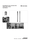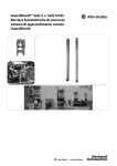
1
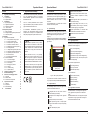
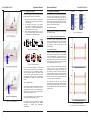
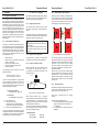
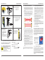
Operation Manual
GuardShieldTM Safe 2
Safety Light Curtain
GuardShield Safe 2
Operation Manual
Operation Manual
GuardShield Safe 2
help protect personnel working on or near machinery.
provide
2
3
GuardShield Safe 2
Operation Manual
Content
1. Approvals and Conformity
2. Introduction
1.
2.
TÜV Rheinland Product Safety GmbH, performed the
CE - type examination according to the machinery
directive EC/98/37, appendix VI and the respective
standards ICE 61496.
GuardShield Safe 2 safety light curtains are active
optoelectronic protective equipment (AOPE) type 2
and comply to annex IV of the European Machinery
Directive EC/98/37 and IEC 61496 as a safety
component.
The GuardShield Safe 2 is offered with a 30mm
resolution in Guard Only mode.
The CE - conformity declaration and the product
approval certification (TÜV) is available on the homepage www.Rockwell Automation.com.
All ROCKWELL AUTOMATION products are
developed and manufactured following generally
accepted rules in industry and in compliance with a
total quality management system ISO 9001: 2000.
Warning
GuardShield Safe 2 systems are only a safety
protection device if all instructions in this manual
and in the related documents are carefully followed
and fully complied with. In addition the installer
is respon-sible to comply with all local laws and
standards.
2.1.
Tolerant to dust, dirt, pollution
Short circuit protected semiconductor outputs
Electrical interface compatible to industry
standard
Built-in diagnostic LED or optical interface for
quick trouble shooting
Very compact design: 30 x 40 mm (1.2” x 1.6”)
Wide standard product range for resolution,
protective height, type of application
System design
GuardShield Safe 2 safety light curtains consist of a
transmitter and a receiver, each having a standard
built-in intelligent laser alignment system ILAS.
(Figure 1).
This allows a much easier adjustment during installation
and system testing compared to conventional safety
light curtains.
Intelligent Laser Alignment System ILAS
Optical synchronisation, no electrical cable
needed between transmitter and receiver
Maintenance-free and cost effective
3. Applications
3.1.
Entry / exit safeguarding
Detection capability
(resolution)
If these instructions are not (or only partially)
followed, this may lead to serious injury or even
death and legal action against the responsible
installer or system integrator. In such a case claims
against ROCKWELL AUTOMATION are not valid.
Typical applications
Depending on the risk analysis GuardShield Safe 2
systems are used for (Figure 2):
Point-of-operation safeguarding
Protection height
Approvals and Conformity
4
Introduction
5
2.1. System design
5
2.2. Special features
5
3.
Applications
5
3.1. Typical applications
5
3.2. Applications restrictions
5
3.3. Application conditions
6
3.3.1. Corner mirrors
6
4. Principles of operation
7
4.1. Mode of operation
7
4.2. Intelligent Laser Alignment System ILAS 7
4.3. Perimeter systems
7
5. Installation
8
5.1. Regulations and standards
8
5.1.1. Safety distance to danger point
8
5.1.2. Height of protective field
8
5.1.3. Response time – light curtain
8
5.1.4. Distance to reflective surfaces
8
5.1.5. Multiple light curtain arrangement 9
5.1.6. Mounting brackets
9
5.1.7. Intelligent Laser Alignment System ILAS 10
5.1.8. Adjustment procedure without ILAS 11
5.1.9. Adjustment procedure with ILAS
11
5.1.10. Remarks to ILAS
11
5.1.11. Testing the protection field
11
5.2. Electrical installation
12
5.2.1. Connection diagram
12
5.2.2. Test input to transmitter
12
5.2.3. Power supply
13
5.2.4. Bringing into operation
13
5.2.5. Outputs
13
5.2.6. Trouble shooting
13
5.2.7. Optical Interface
14
6.
Interfacing to safety devices
14
7.
Dimensional drawings
16
8.
Selection of a safety light curtain
17
8.1. Check list
17
8.2. Selection table
17
8.3. Accessories / Components
18
9.
Inspection and service
19
9.1. Cleaning
19
9.2. Inspections
19
9.3. Decommissioning
19
10.
Technical Data
20
GuardShield Safe 2
Operation Manual
Hazards area safeguarding
Combination of entry and area safeguarding
Combination of entry, area and point-of-operation safeguarding
Typical areas of applications are:
This instruction manual is part of the light curtain
GuardShield Safe 2. It must be kept accessible
dur-ing the whole life cycle for everybody who is in
charge of installation, operation, maintenance and
safety control.
Processing machinery
Conveyor machines
Intelligent Laser Alignment System ILAS
Operating range
Automated paint shops
Typical markets are:
Figure 1: Main system parameters
Semi conductor industry
Paper processing
The products are a modular construction housed in a
very compact and sturdy extruded aluminium profile.
2.2.
Wood processing
Glass manufacturing
Special features
The outstanding features of the safety light curtain
systems of GuardShield Safe 2 are:
Integrated self test mode, which make an
external testing unnecessary
Configured with intelligent laser alignment
ILAS
Hand protection (30 mm resolution)
Textile industry
3.2.
Applications restrictions
GuardShield Safe 2 is not designed and approved
for any application in explosive EX or radioactive
areas.
GuardShield Safe 2 does not comply with the optical
requirements of a type 4 light curtain according the
international standard IEC 61496.
Wide dynamic range with a compact profile
type: 30 mm resolution: 0 m up to 6 m operating
range,
Max. 256 beams per system
4
5
GuardShield Safe 2
Operation Manual
3.3.
Application Conditions
The safe application of the light curtain systems
GuardShield Safe 2 needs certain precautions:
1. The control unit of the machine or system must be
able to be electrically stopped and the stop time
must be known.
2. The hazardous moving parts of the machine
must always be stoppable and must achieve a
safe position or complete standstill within the
specified stop time of the machine.
3. When installing GuardShield Safe 2, the only
way to access the hazard must be through the
sensing field of the GuardShield Safe 2.
GuardShield Safe 2
Operation Manual
4. Principles of Operation
The transmitter sends coded infrared light pulses to
the receiver, which evaluates them. If an object e.g.
a hand (30 mm) penetrates the protective field, the
redundant solid state Output Signal Switching Devices
(OSSD) of the receiver switch off to stop the machine.
As soon as the protective field is cleared, both outputs
switch on again (automatic restart).
4.1.
Mode of operation
GuardShield Safe 2 operates in the guard only mode
with automatic restart.
4.2.
Transmitter
Receiver
POWER
Power on
(orange)
OK
Normal operation
(green)
Output active
(green)
TEST
Test input
(red)
Output inactive
(red)
Optical
(IR light)
Optical
(IR light)
POWER
Power on
(orange)
Figure 5: LED Indicators
Intelligent Laser Alignment System ILAS
The ILAS is a most convenient feature to make
alignment a pleasure. The ILAS can be activated at
any time during installation or operation. It provides
the possibility to check if the light curtain is still
perfectly aligned.
Figure 3: Correct installation
Figure 4: Incorrect installation
For the professional installation and connection,
please consult the relevant laws and regulations.
The safety officer of the manufacturing facilities,
the local authorities (OSHA in USA, HSE in GB)
or the respective industry associations as well as
the intensively trained employees of ROCKWELL
AUTOMATION are available for any safety related
queries.
3.3.1.
Corner mirrors
The protective field between transmitter and receiver
can be guided around a corner using a mirror to
allow safeguarding of two or three hazardous areas.
Note that using one mirror will help reduce maximum
operating range by approx. 15 %.
4.3.
Perimeter systems
Perimeter systems are usually produced by means of
several single beam light barriers. But the flexibility
of the GuardShield Safe 2 system allows also the
production of vertical entry safeguarding according to
the standard EN 999. Such systems are composed of
active and passive elements in one compact pro-file.
The element length of each is 120 mm.
The big advantage of GuardShield Safe 2 Perimeter
systems is the easy way of mounting and the
uncomplicated way of starting up the operation. The
time needed to connect the wires and aligning the
optics is drastically reduced in comparison to standard
Perimeter systems consisting of single beam light
barriers, where often mirrors are also included which
can only be positioned with difficulties.
The protective field and the active elements
respectively, are clearly recognized as black surfaces
with the integrated optical lenses. The not monitored
areas (passive elements) are also clearly indicated as
yellow surfaces.
It is not recommended to use more than two mirrors
due to alignment difficulties that may occur.
Figure 2: Typical Applications
6
As accessories two types of mirrors are available,
with different mounting plates and sizes. Detailed
information
is
available
from
ROCKWELL
AUTOMATION.
Figure 6: Perimeter Systems
(2 and 3 beams), accord. to EN999 (1998)
7
GuardShield Safe 2
Operation Manual
5. Installation
5.1.
Regulations and standards
The compliance with the fundamental health &
safety requirements as detailed in the EU Machinery
Directive EC/98/37 has to be achieved with the correct
implementation of safety components. With the help
of a hazard analysis as laid out in EN 292 and EN
1050, a comprehensive safety evaluation has to be
made when designing and planning machinery and
machinery control equipment. If Active Optoelectronic
Protective Devices (AOPD) is used, the required
safety distances, sufficient protective height and all
application conditions must be considered during the
planning phase.
5.1.1.
Safety distance to danger point
According to the standards, the GuardShield Safe 2
light curtain and the point of danger must be separated
by a defined safety distance. This minimum distance
safeguards that the danger point may only be reached
after the hazardous motion has stopped. The safety
distance (see also standards EN 294, EN 775, EN
811, EN 999) depends on
•
•
•
•
•
Machine stop time
Response time of the protective device (light
curtain + safety relays)
Resolution of the protective device
Approaching speed to the danger point
Position of the AOPD
The approaching speed is dependent on safety
distance S as follows:
S = 1.6 mm / ms x T + 850 [mm]
5.1.2.
Height of protective field
The protective field is clearly visible as the black
area with the optical lenses on the transmitter and
receiver.
Warning:
The laser beams of the ILAS are not part of to the
protective field.
Use only the protective field as mentioned on the
product label. Otherwise serious injury or death
may occur.
5.1.3.
Response time – light curtain
For S > 500 mm
S = 1.6 mm / ms x T + 8 x (d - 14)
S = Safety distance in mm
T = Total response time in ms
(machine stop time + GuardShield Safe 2
response time + safety relay response time)
d = Resolution of GuardShield Safe 2 in mm
In the case of perimeter systems (chapter 4.5) or light
curtains with a resolution d > 40 mm the safety distance
is calculated for vertical mounted light curtains and
horizontal approach, according to the formula:
8
When using several optoelectronic safety devices in
the same application, the systems should be installed
in such a way that they cannot interfere with each
other. Care must be taken that each receiver only
receives light from its own transmitter (Figure 8).
Transmitter
Receiver
Transmitter
Receiver
Receiver
Receiver
The response time tR is found on the product label,
Configuration Tool or from the selection tables 8.2.
5.1.4.
Distance to reflective surfaces
Reflective surfaces may cause reflections within
the transmitter and receiver aperture angle, i.e.
an interruption of the protective field would not be
recognized (Figure 7).
dangerous point
E
Transmitter
The safety light curtain has been thoroughly tested
against light interferences according to the stringent
requirements of IEC 61496. Nevertheless any direct
interference into the receiver with other infrared
sources like through beam photoelectric sensors,
laser scanner, transmitters etc. should be avoided.
Mechanical installation
Be aware that a rigid, flat base, isolated against
shock and vibration should be selected to mount the
GuardShield Safe 2. This in combination with the
standard mounting brackets set will keep the initial
alignment during operation even in harsh industrial
environments.
R
S2
5.1.6.
optical axis
Transmitter
Figure 8: Multiple light curtain arrangement
R
Mounting brackets
The backside of the light curtain profile has continuous
grooves to fix the mounting brackets at any position
along the light curtain housing (Figure 18).
reflective surface
For 100 mm ≤ S ≤ 500 mm:
S = 2 mm / ms x T + 8 x (d - 14)
Multiple light curtain arrangement
In addition the height of the protective field A is found
on the label of each system and in the selection tables,
described in chapter 8.2 (resolution 30 mm).
S ≤ 500 mm, speed = 2 mm / ms
S > 500 mm, speed = 1.6 mm / ms
In cases of ‘vertical’ installation of the light curtains
within an industrial environment and a resolution of
the light curtain system d, (where 14 mm ≤ d ≤ 40
mm), the safety distance S to the point of danger is
calculated according to the formula:
5.1.5.
More detailed information regarding safety distance
and safety height can be found in EN 999 or EN 294,
depending on mounting type of application.
GuardShield Safe 2
Operation Manual
Figure 7: Distance to reflective surfaces
Should reflective surfaces arise, i.e. aluminium
container passing near the light curtain or if the danger
point itself is reflective, i.e. a steel blade, the safety
distance S2 must be increased, such that no reflective
surface lies within the distance S2.
The increase of the safety distance is dependant of
the actual operation range R according to IEC 61496
and may be calculated as follows:
GuardShield Safe 2:
S2 = 131 mm
S2 = R x 0.0437
Each system is delivered with four mounting
brackets.
Available mounting brackets (Figure 9):
• Vertical mounting brackets for mounting the light
curtain in the vertical axis of the light curtain.
(± 4o adjustable)
• POC AND SICK FGS mounting profiles (not
adjustable)
for R < 3 m
for R ≥ 3 m
9
GuardShield Safe 2
Operation Manual
5.1.8.
11
Standard mounting brackets
M6 x 40
•
•
GuardShield Safe 2
Operation Manual
1.
For side mounting
Adjustable by ± 4°
2.
M4 x 16
Adjustment Procedure without ILAS
5.1.9.
Mount the transmitter and the receiver with the
adjustable mounting brackets. Make sure that
the longitudinal axis of both are oriented parallel.
A spirit level might help to find the correct
position.
Take care that the receiver and transmitter are
oriented in the same direction. This means, the
controllers of the transmitter and receiver have
to be at the same end of the protective field.
It is not allowed to mount GuardShield Safe 2
systems turned by 180° (Figure 10).
•
For mounting in the vertical
axis of the light curtain
Adjustable by ± 4°
Incorrect
Receiver
•
Transmitter
Vertical mounting brackets (optional)
M6 x 40
Correct
29
Receiver
Transmitter
M4 x 12
Adjustment Procedure with ILAS
1. Mount the transmitter and the receiver with the
adjustable mounting brackets. Look for that the
longitudinal axis of both are oriented parallel. Take
care that receiver and transmitter are orented in
the same direction. This means, the controllers of
transmitter and receiver have to be at the same
end of the protective field. It is not allowed to
mount GuardShield Safe 2 systems turned by 180°
(Figure 10).
2. The ILAS is activated by touching the hand symbol
at the transmitter resp. at the receiver.
3. Adjust the transmitter and receiver in a way that
both laser points hit the laser target on the opposite
unit. Small deviations are harmless as long as they
are within the aperture angle.
4. Tighten all screws firmly.
5. Switch the ILAS off when aligned.
6. Control the operation of the light curtain by using
the test rod (Figure 12). Introducing the test rod
into the protective field at any position must lead
to a protective field interruption (shining of the red
LED on the receiver).
5.1.10.
POC AND SICK FGS mounting profile (optional)
Figure 10: Layout of the transmitter / receiver
60
• A special profile which is
compatible with existing
POC AND SICK FGSmountings.
• Adjustments has to be made
with the POC AND SICK
FGS-mountings, if available.
3.
180° Mounting, rotation ±
90°, for applications where
the mounting angle is not
set using the mounting
frame.
4.
5.
6.
Figure 9: Different mounting brackets for a GuardShield Safe 2 / Safe4
The mounting brackets contain all necessary
mounting parts and a separate instruction sheet to
ensure that the parts are assembled properly.
To switch on ILAS:
•
Touch the hand symbol
Operation: Laser beam is blinking
5.1.7.
Intelligent Laser Alignment System ILAS
WARNING: Class 2 Laser
Do not expose your eyes to the
laser beam to prevent exposure to
dangerous radiation!
Turn ILAS off if not used!
To switch off ILAS:
•
Touch the hand symbol
again
•
Automatically after 5 minutes
7.
After aligning the longitudinal axis of transmitter
and receiver, rotate the receiver around the
longitudinal axis to find the receiving angle.
During rotation, the receiving angle is shown
when the green LED of the receiver controller is
on.
Adjust the receiver to the centre point of the
operating angle, and tighten.
After aligning the receiver rotate the transmitter
to find the emitting angle. During rotation, the
emitting angle is shown when the green LED of
the transmitter controller is on.
Adjust the transmitter to the centre point of the
operating angle, and tighten.
Control the operation of the GuardShield Safe
2 light curtain by using the test rod (Figure 12).
Introducing the test rod into the protective field
at any position must lead to a protective field
interruption (shining of the red LED on the receiver).
Due to dimensional tolerances the red ILAS light
spot deflects from the target center when the light
curtain is aligned optimal in the center of the operating
range. The optimal operating point can be found after
alignment with ILAS (chapter 5.1.9) when moving the
axis in X- (left, right) and Z- (up, down) direction. The
optimal operating point is in the middle of the two end
points, where the receiver output switches from active
to inactive condition.
D
On optimal alignment of the light
curtain the ILAS light point can deflect
from the ILAS target point. The
maximum deflection adds up to the
following value due the operating
distance:
2m
6m
9m
18 m
30 m
R = 7 mm
R = 20 mm
R = 30 mm
R = 60 mm
R = 99 mm
R
D = 7 mm
D = 21 mm
D = 32 mm
D = 63 mm
D = 105 mm
Figure 11: Adjustment with ILAS
5.1.11.
When mounting Perimeter Systems adjust the heights
according to the recommendations in the standard EN
999.
Remarks to ILAS
Testing the protection field
After Installation and Alignment of the GuardShield
Safe 2 safety light curtain, the protection field has
to be tested with the test rod for the corresponding
resolution (30 mm) according Figure 12.
When mounting Perimeter Systems adjust the heights
according to the recommendations in the standard
EN 999, RIA 15.06 or according to the prevailing local
regulation.
10
11
GuardShield Safe 2
Operation Manual
Transmitter:
The following points have to be considered:
• In case of operation in the modus “self monitoring”
both OSSD outputs have to be connected
separately to the safety switching of the machine.
Pin 5
= PE
Pin 3
Pin 4
=0V
Receiver
Transmitter
= Test 1
Pin 2
Pin 1
•
= Test 2
= + 24 VDC
GuardShield Safe 2
Operation Manual
GuardShield Safe 2:
In case of connecting an external test it could be
that, depending on the test type, only one OSSD
output (OSSD1 or OSSD2) has to be considered.
The automatic power-up test will only be successful,
if the transmitter and receiver are properly aligned,
correctly connected and the protective field is not
interrupted.
Any intrusion of an object into the protective field will
switch the OSSDs off within the specified response
time and the LED at the receiver toggles from green
to red.
5.2.5.
Figure 12: Correct testing of the protective field using
a test rod
5.2.
5.2.1.
Pin 5
= PE
Connection diagram
Time Value in ms
Response time on test signal
t1
≤ tR + 15
Time to test
t2
> t1
Restart time after test
t3
≤ 800
Pin 3
Pin 4
= OSSD 1
Electrical Installation
=0V
Pin 2
= OSSD 2
Pin 1
= + 24 VDC
1
Test input
Transmitter
3
Figure 14: M12/5 Pin connector
Important information:
Safety devices for connection of GuardShield Safe 2
the must be built with PNP logic. The outputs will be
periodically controlled for short-circuit and cross-fault
detection.
open
OSSD 1 / OSSD 2
t1
Receiver
3)
+24 VDC
2
t3
t2
Transmitter
The output voltage at the solid-state outputs is
dependant on the power supply and the output load
(see chapter 11 Technical Data).
Figure 16: Test timing diagram
0V
2)
1)
tR means the response time of the respective
GuardShield Safe 2 type (see product label).
4
5
Not connected
1) Operation with internal test
2) Test using a relay contact
3) Test using a PNP output
Receiver
0V
1) Operation with internal test
2) Test using a relay contact
3) Test using PNP output
RL
OSSD 1
4
+24 VDC
1)
0V
RL
Test 2
2
Test 1
PE
OSSD 1
PE
+24 VDC
OSSD 2
1
Pin 1 (brown)
Pin 3 (blue)
Pin 4 (black)
0V
+24 VDC
Pin 2 (white)
Pin 1 (brown)
Pin 5 (grey)
Pin 3 (blue)
7
Pin 2 (white)
Not connected
Pin 4 (black)
Pin 5 (grey)
6
3
OSSD 2
2)
Not connected
Not connected
7
Figure 13: Terminal block connection (see also
Figure 18)
Figure 15: Wiring of the connecting cables of the
M12/5 Pin connector
Transmitter and receiver are supplied with M12/5
pin connectors The wiring is given in Figure 14 and
Figure 15.
5.2.2.
Internal test
Description
Continuous test current
I
Peak test current
IP
Time of peak test current
tP
Internal test
Short circuited (closed)
Open
5.2.3.
3)
5
6
Test input to transmitter
Normally the test input at the transmitter is installed
with a short circuit jumper to activate the transmitter. If
an external test is desired, a contact can be connected
to the test input (Figure 13).
12
The two redundant Output Signal Switching Devices
(OSSD) are fully monitored. Any short circuits are
detected. The maximum load is 0.4 A, higher currents
are limited through short circuit protection. Increased
output loads may be realized using external safety
interfaces.
short circuited
The transmitter and receiver are connected to the
machine control using a 5-wire cable.
For the transmitter and the receiver two M12 (for
cable - Ø 3 ... 6.5 mm)
Outputs
The timing of test input is as follows (Figure 16):
Receiver:
Transmitter
Active
Inactive
Value
10 mA
100 mA
20 µs
Test LED
Transmitter
Green
Red
Power supply
GuardShield Safe 2 safety light curtains are devices
of electrical safety level III (extra low voltage). 24 VDC
± 20 % has to be supplied by a power supply that
complies with IEC / EN 60204 and IEC / EN 60742.
Such a power supply meets the electrical safety
requirements and maintains the minimum power of 18
VDC during 20 ms even in the event of voltage dips.
5.2.4.
5.2.6.
Trouble shooting
Possible errors and operation status are indicated with
the LED indicators on the transmitter and receiver.
Also the Optical Interface has an option that can be
used for the diagnostics
Following combinations are relevant:
Table 1: Transmitter
Status
No power supply
(external)
Test input closed
(external)
Test input open
(external)
Controller error
(internal)
Protective field error
(internal)
Orange
(Power)
off
LED
Green
(ok)
off
Red
(Test)
on
on
on
off
on
off
on
flashing
off
on
flashing
off
flashing
Bringing into operation
After the power supply has been applied to the
GuardShield Safe 2 and the automatic power-up test
is successfully completed (power up test time < 3 s)
the green LED on the receiver and transmitter will light
on. The system is now ready to operate.
13
GuardShield Safe 2
Operation Manual
Table 2: Receiver
+24 VDC
Status
LED
Orange Green
(Power)
No power supply
(external)
No sufficient power
(external)
OSSD on (on-load operation,
protective field not interrupted,
normal)
OSSD off (off-load operation,
protective field interrupted or
insufficient alignment of the
system)
OSSD error (external, short
circuit between OSSD 1 and
OSSD 2, towards 0 V and off
24 VDC)
Controller error (internal)
Protective field error (internal)
off
on
off
off
on
off
flashing
off
on
irregular
flashing
flashing
off
flashing
off
on
off
flashing
Normal operation
5.2.7.
2
3
4
5
6
7
2 3
4
5
6
7
1 3 23 24
A1 S33 S34
MSR 4X
all 3s
short time
Internal error (orange LED is irregularly flashing):
Please
contact
the
nearest
ROCKWELL
AUTOMATION representative.
Transmitter
Receiver
Trans mitter
(Protective (Protective
field not
field
interrupted) interrupted)
off
off
on
1
1
Red
External error: An external interface error can be
resolved by correcting the installation, due to
1. Receiver: short circuit of both OSSDs, of OSSD
to Usp, of OSSD to GND
2. Transmitter: Test input open
3. No or too low power supply
Test input closed
Test input closed
Test input open
GuardShield Safe 2
Operation Manual
Receiver
Operation status
OSSD on
OSSD off
OSSD off
Protective field free
Protective field interrupted
Test active
Optical Interface
As an accessory Rockwell Automation offers an
Optical Interface including a software package for
extended diagnostic purposes.
Figure 17: Optical Interface
The adapter may be snapped on the controller during
normal operation and may be connected via the
interface to a MS-Windows personal computer for
diagnoses purposes. A detailed description about
extended diagnostic features is shipped with the
diagnostic package.
The Optical Interface offers apart from the diagnosis
of operating conditions, the possibility to select and
analyse the length of the interrupted protective field.
S21 S22 A2
14 S11 S12
0 VDC
Figure 18: Diagram for automatic reset mode with ROCKWELL AUTOMATION MSR 42
6. Interfacing to safety devices
The interfacing of the light curtain with the machine
control has to be control reliability, i.e. a correct
interface with a safety PLC or safety relays with
positive guided relay contacts.
Figure 18 - Diagram for automatic reset mode shows a diagram of a typical emergency stop relay
component.
Other applications are mentioned in the application
note “Safety Interfaces with GuardShield Safe 2”, on
the ROCKWELL AUTOMATION homepage.
Danger
The safety devices and the interconnection to
the machinery have to comply with the basic
safety requirements as mentioned in the current
regulations and standards.
Direct interfacing of a safety light curtain to machine
control that does not meet the necessary safety
integrity level, i.e. use of general purpose PLCs or
general purpose relays can cause serious injury or
death of persons.
Consult a professional safety engineer!
Danger
14
15
GuardShield Safe 2
7.
Operation Manual
Dimensional drawings
8.
Selection of a safety light curtain
8.1.
Transmitter
Check list
57
M16
M12
ILAS Emitter
ILAS target
25
ILAS Emitter
Start of protective field
8.2.
4. Corner mirrors
Using corner mirrors allow safeguarding two or
three protective fields with one light curtain.
Each corner mirror reduces the operating range
by approximately 15 % per mirror.
Catalog No.
ILAS target
4
30
3
Pin 1
2
Pin 7
Figure 19: Dimensional drawing, cross Section
Selection table
Table 3: 30 mm resolution with ILAS
3
40
1. Regulations
Look up carefully the actual regulations and
codes applicable to the particular application in
your country. Local authorities and professional
organisations
as
well
as
ROCKWELL
AUTOMATION representatives will provide
necessary assistance.
USA: Occupation
Safety
and
Health
Administration OSHA, others like ANSI, RIA and
further professional organisations
GB: Health and Safety Executive HSE, safety
consultants and professional organisations
2. Protective field
Determination of
• required operating range,
• protective height (available in increments of 120
mm),
• resolution (object detection capability: 30 mm)
• and configuration of light curtain (special
configuration with extension modules)
B
A
3. Response time
The response time tR-BWS of GuardShield Safe
2 can be found on the product label and in the
selection table (next section). The response
time can also be calculated with the Optical
Configuration Tool.
In consideration of following points the selection of a
proper GuardShield Safe 2 safety light curtain will be
simplified:
145
16
Operating range, protective height and special
configuration must be chosen so that the danger points
are only accessible through the protective field.
Receiver
35
Cross section with
connector pinning
GuardShield Safe 2
Operation Manual
Detail
mounting groove
445L-P2S0120YD
445L-P2S0240YD
445L-P2S0360YD
445L-P2S0480YD
445L-P2S0600YD
445L-P2S0720YD
445L-P2S0840YD
445L-P2S0960YD
445L-P2S1080YD
445L-P2S1200YD
445L-P2S1320YD
445L-P2S1440YD
445L-P2S1560YD
445L-P2S1680YD
445L-P2S1800YD
445L-P2S1920YD
Protective Total length B
height A
(mm)
(mm)
120
290
240
410
360
530
480
650
600
771
720
891
840
1’011
960
1’131
1’080
1’252
1’200
1’372
1’320
1’492
1’440
1’612
1’560
1’733
1’680
1’853
1’800
1’973
1920
2093
Response time tR Max. range
(ms)
(m)
7.8
10.5
13.1
15.8
18.4
21.1
23.7
26.3
29.9
31.6
34.3
36.9
39.6
42.2
44.9
47.6
6
6
6
6
6
6
6
6
6
6
6
6
6
6
6
6
Resolution Weight per pair
(mm)
(kg)
30
30
30
30
30
30
30
30
30
30
30
30
30
30
30
30
1.0
1.4
1.8
2.2
2.6
3.0
3.5
4.0
4.0
4.5
5.0
5.5
6.0
6.5
7.0
7.5
17
GuardShield Safe 2
8.3.
Operation Manual
9.
Accessories / Components
Table 4
ROCKWELL AUTOMATION
Part No.
445L-AC5SH-5
Operation Manual
Inspection and service
All light curtains contain only electronics and therefore
need limited maintenance.
Description
9.1.
5 m PVC shielded cable with M 12 / 5 pin connector, Figure 13
445L-AF6140
Standard mounting kit (4 pieces)
445L-AF6141
Adjustable mounting kit
445L-AF6142
Shock mount kit
445L-AF6144
Mounting kit for POC AND SICK FGS adapter (4 pieces)
445L-AF6150
Optical Interface (incl. software)
Catalog Number
440L-AM0750300
440L-AM0750450
440L-AM0750600
440L-AM0750750
440L-AM0750900
440L-AM0751050
440L-AM0751200
440L-AM0751350
440L-AM0751500
440L-AM0751650
440L-AM0751800
None Available
Wide Corner Mirror,
Long range 4...15M
Cleaning
The optical windows are to be cleaned with nonaggressive materials only. The interval between
cleaning is dependant on the air pollution at the
installation.
Do not use aggressive solvents or abrasive
substances. Otherwise range reduction and false
switching could arise.
Table 5 - Corner Mirror
GuardShield Safe 2 / Safe 4 Narrow Corner Mirror,
Protective Height (mm)
short range 0...4M
120 / 240
360
480 / 600
720
840
960
1080 / 1200
1320
1440
1560
1680 / 1800
1800
GuardShield Safe 2
Catalog Number
440L-AM1250300
440L-AM1250450
440L-AM1250600
440L-AM1250750
440L-AM1250900
440L-AM1251050
440L-AM1251200
440L-AM1251350
440L-AM1251500
440L-AM1251650
440L-AM1251800
None Available
9.2.
Inspections
The light curtain must, depending on the valid
regulations, be periodically tested by qualified and
trained persons.
The function of the light curtain can be tested with the
supplied test rod, which has a diameter corresponding
to the resolution of the light curtain. The status is
indicated through the LED display in the ROCKWELL
AUTOMATION GuardShield Safe 2 light curtain.
Functional Test
The function of the light curtain can be tested using
the test rod, (Figure 12), which has a diameter
corresponding to the resolution of the light curtain.
The status is displayed at the LED on the transmitter
or receiver. The status can be easily read from the
trouble shooting labels “Transmitter Status” and
“Receiver Status” (table 1 and 2, page 13).
9.3.
Decommissioning
The safety light curtain may only be removed, if the
machinery or assembly line will be closed definitively.
This has to be done by removing the main supply
from the machinery. It must be impossible to bring the
machinery into operation without using tools.
The light curtain can be reused provided the current
regulations are taken into consideration.
If the light curtain has to be disposed, it can easily
be disassembled and recycled using state of the art
recycling technology and following current disposal
regulation. It does not contain harmful materials
except small quantities of materials used in electronic
PCBs.
18
19
GuardShield Safe 2
Operation Manual
Operation Manual
GuardShield Safe 2
10. Technical Data
Table 6
Description
Value
Remarks
Profile length
120 ... 1920
120mm increments
Operating range
0 ... 6 m,
Resolution 30 mm
Object detection capability
30 mm
(Resolution)
Power supply Usp
24 VDC ± 20 %
Power supply ripple
< 10 % of Usp
Equipment Class
III
PELV, IEC 60 204-1
VDE 0106 part 100
Time for self check when switching on Usp < 3 s
20
Current consumption
< 500 mA
Outputs, short circuit proof
2 x PNP, 0.3 A
Max. capacitive load 0.5 µF
Output voltage
> Usp – 1
Load 0.1 A
Response time tR-BWS
Selection table
Connector
M 12, 5-Pin
Connection cable
Max length 5M
Cross section max.
1.5 mm2
Outside diameter of cable
3 ... 6.5 mm
Mode of operation
Guard only with automatic restart
Safety category
Type 2
Standards
IEC 61496 part1+2
No-load operation
for M12
IEC 61496
Electromagnetic compatibility (EMC)
IEC 61 496 part 1
Enclosure rating
IP65
Temperature range
0 ... +55°C
Operation with ILAS
-20 ... +60°C
Storage / transport
Relative air humidity
15 ... 95 %
Not condensing
Enclosure
Aluminum profile 30 x 40 mm
Optical window
Polycarbonate, bonded
Enclosure treatment
Polyester powder coated
ILAS
Laser class 2
Dimensions
Dimensions and selection tables
Weight
Selection tables
EN 60 825
21
GuardShield Safe 2
22
Operation Manual
Operation Manual
GuardShield Safe 2
23
Please contact us for Technical Assistance:
In the U.S.:
1-440-646-5800
Outside U.S.: 001-440-646-5800
On line:
http://www.ab.com/safety
P N - 29485 July 2008
Copyright © 2008 Rockwell International. All right reserved. Printed in USA