1
A
GROUP 21
TRANSMISSIONS
CONTENTS
Page
MANUAL TRANSMISSIONS—3 SPEED . . .
SPECIFICATIONS
54
89
Page
TIGHTENING REFERENCE
TORQUEFLITE TRANSMISSIONS
10
1
TORQUEFL1TE TRANSMISSION (A-727-B)
INDEX
Page
G e n e r a l Information . . . . . .
1
Hydraulic Control S y s t e m
11
Operating Instructions
12
Service Diagnosis
12
S e r v i c e in V e h i c l e . . . . . . . . .
.........
. . . 18
Air P r e s s u r e T e s t s
25
Aluminum Thread Repair
18
Band Adjustments
22
Console Gearshift
20
Extension H o u s i n g a n d Output S h a f t B e a r i n g . . 26
Extension H o u s i n g Yoke S e a l
26
Gearshift Linkage Adjustment
19
Governor
27
Hydraulic Control P r e s s u r e T e s t s
22
Hydraulic Control P r e s s u r e A d j u s t m e n t s
24
Lubrication
19
Neutral Starting S w i t c h
21
Parking L o c k C o m p o n e n t s
28
S p e e d o m e t e r Pinion
—
26
Throttle Rod Adjustment
22
Valve Body and A c c u m u l a t o r Piston
29
S e r v i c e Out of V e h i c l e
29
A s s e m b l y — S u b - A s s e m b l y Installation
48
Disassembly—Sub-Assembly Removal
I n s t a l l a t i o n — T r a n s m i s s i o n , Converter a n d
Drive Plate
Fluid L e a k a g e
Recondition S u b - A s s e m b l i e s . . . . . . . . . . . . . . . . .
A c c u m u l a t o r Piston a n d S p r i n g
Extension Housing B u s h i n g R e p l a c e m e n t
Front C l u t c h
Governor a n d Support
Kickdown Servo a n d B a n d
L o w - R e v e r s e Servo a n d B a n d
Oil P u m p and Reaction S h a f t S u p p o r t . . . . . . .
Overrunning C l u t c h
Parking L o c k S p r a g
Planetary G e a r Train
Rear Clutch
Valve Body A s s e m b l y . . . . . . . . . . . . . . . . . . . . . .
R e m o v a l — T r a n s m i s s i o n a n d Converter
P u m p Oil S e a l
Starter Ring G e a r
Torque Converter F l u s h i n g
Specifications
Tightening R e f e r e n c e
Page
32
50
52
34
38
38
41
38
47
47
39
46
38
45
43
35
29
32
30
31
69
70
GENERAL INFORMATION
identification
c l u t c h r e t a i n e r . T h e h y d r a u l i c s y s t e m consists of a n
m a r k i n g s a r e cast i n r a i s e d l e t t e r s about 3 / 8 i n c h
oil p u m p , a n d a single v a l v e body w h i c h c o n t a i n s a l l
h i g h o n t h e l o w e r left s i d e of t h e t r a n s m i s s i o n b e l l
of the v a l v e s e x c e p t the g o v e r n o r v a l v e .
T h e TorqueFlite Transmission model
housing.
T h e A-727-B
V e n t i n g of t h e t r a n s m i s s i o n i s a c c o m p l i s h e d b y a
TorqueFlite
Transmission servicing
procedures a r e i n general the same for a l l models.
C A U T I O N : T r a n s m i s s i o n operation r e q u i r e m e n t s are
different for each vehicle and engine
combination
a n d some internal parts will be different to provide
for
this. Therefore, when
r e p l a c i n g p a r t s , refer to
the seven digit part number stamped on left side of
the t r a n s m i s s i o n oil pan flange.
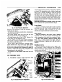
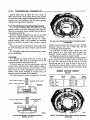
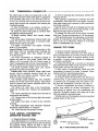
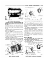
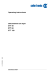
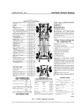
The
A-727-B
transmission
( F i g . 1) c o m b i n e s
torque c o n v e r t e r a n d a fully-automatic
a
3-speed g e a r
system. T h e converter housing and transmission case
are a n integral aluminum casting. T h e transmission
consists of t w o m u l t i p l e d i s c c l u t c h e s , a n o v e r r u n -
drilled
passage through
the upper
p a r t of t h e o i l
pump housing.
T h e torque c o n v e r t e r i s a t t a c h e d to t h e c r a n k s h a f t
through a
flexible
d r i v i n g plate. C o o l i n g of t h e con-
v e r t e r is a c c o m p l i s h e d b y c i r c u l a t i n g t h e t r a n s m i s s i o n
fluid
t h r o u g h a n oil-to-water
type cooler, located i n
t h e r a d i a t o r l o w e r tank. T h e t o r q u e c o n v e r t e r a s s e m bly i s a s e a l e d u n i t w h i c h c a n n o t b e d i s a s s e m b l e d .
T h e t r a n s m i s s i o n fluid i s
filtered
by an internal
" D a c r o n T y p e " filter a t t a c h e d to t h e l o w e r s i d e of t h e
v a l v e body a s s e m b l y .
E n g i n e torque
is transmitted
to t h e torque
con-
ning clutch, two servos and bands, and two planetary
v e r t e r t h e n , t h r o u g h t h e i n p u t shaft to t h e m u l t i p l e
g e a r sets to p r o v i d e t h r e e f o r w a r d ratios a n d a r e -
d i s c c l u t c h e s i n t h e t r a n s m i s s i o n . T h e p o w e r flow de-
v e r s e ratio. T h e c o m m o n s u n g e a r of t h e p l a n e t a r y
p e n d s o n t h e application of t h e c l u t c h e s a n d b a n d s .
g e a r sets i s c o n n e c t e d to t h e f r o n t c l u t c h b y a d r i v i n g
R e f e r to " C l u t c h E n g a g e m e n t a n d B a n d
s h e l l w h i c h i s s p l i n e d to t h e s u n g e a r a n d to t h e f r o n t
Chart."
Application
FLEXIBLE DRIVE PLATE
ENGINE C R A N K S H A F T
NN116B
Fig. I— TorqueFlite
Transmission
and Torque Converter
(A-727)
A
-TORQUEFLITE—TRANSMISSION
—
ENGINE
21
RUNNING
NN34C
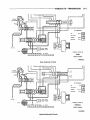
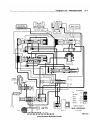
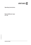
Park Hydraulic
Circuits
ENGINE iUNNSNG
HH35C
Neutral Hydraulic
Circuits
21-4
TRANSMISSION—TORQUEFLITE
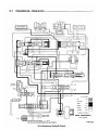
Drive-Breakaway
Mydmmim
Circuits
A,
TORQUEFLITE—TRANSMISSION
21-5
SERVO
ftEAft
• H I CLUTCH
CiUiCH
CONVERTER
30-75 psi
L U B R I C A T I O N . . . . . . . 5-30 psi
|"
j
~
CONTROL SYSTEM IN
TO LUB.
DRIVE (SECOND)
PUMP
H A L F THROTTLE
NR734A
Drive-Second Hydraulic
Circuits
j
21-6
TRANSMISSION—TORQUEFLITE
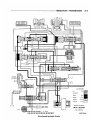
Drive-Direct
Hydraulic
Circuits
——TORQUEFLITE—TRANSMISSION
A
Drive-Kiekdown
Hydraulic
Circuits
21-7
21-8
A
TRANSMISSION—TORQUEFLITE
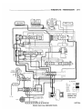
SERVO
REAR CIUICH
I T. C CONTROL VA.
-^^yj,
Pi
j
* ...,^0
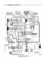
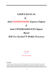
OIL PRESSURES
55 psi
LINE
COOLER
PUMP SUCTION
I&GUIATOR
Jo O
GOVERNOR
6-55 psi
CONVERTER
30-75 psi
LUBRICATION
O CM
5-30 psi
J
CONTROL SYSTEM IN
TO L U B .
^9°°
^
o
c
MANUAL SECOND
HIGH PRESS.
RELIEF VALVE
CLOSED THROTTLE
PUMP
OIL
FILTER
NR7 37A
•
Selector Lever Second—Hydraulic
Circuits
A
TORQUEFLITE—TRANSMISSION
Selector Lever Low—Hydraulic
Circuits
21-9
21-10
A
TRANSMISS10N—T0RQUEFL1TE
Reverse Hydraulic
Circuits
A
TORQUEFLITE—TRANSMISSION
21-11
HYDRAULIC CONTROL S Y S T E M
the t r a n s m i s s i o n (in c o n j u n c t i o n w i t h t h r o t t l e p r e s s u r e ) to c o n t r o l upshift a n d d o w n s h i f t s p e e d s .
T h e h y d r a u l i c c o n t r o l c i r c u i t s on p a g e s 3 t h r o u g h
10 show the position of the v a r i o u s v a l v e s w i t h c o l o r
coded p a s s a g e s to indicate those u n d e r h y d r a u l i c
p r e s s u r e f o r a l l operations of the t r a n s m i s s i o n .
T h e throttle v a l v e t r a n s m i t s r e g u l a t e d p r e s s u r e to
the t r a n s m i s s i o n (in c o n j u n c t i o n w i t h g o v e r n o r p r e s s u r e ) to c o n t r o l upshift a n d d o w n s h i f t s p e e d s .
T h e h y d r a u l i c c o n t r o l s y s t e m m a k e s the t r a n s m i s sion f u l l y a u t o m a t i c , a n d h a s f o u r i m p o r t a n t f u n c t i o n s
to p e r f o r m . I n a g e n e r a l w a y , the c o m p o n e n t s of a n y
automatic c o n t r o l s y s t e m m a y be g r o u p e d into t h e
following b a s i c g r o u p s :
Flow Control
T h e p r e s s u r e s u p p l y s y s t e m , the p r e s s u r e regulati n g v a l v e s , the flow c o n t r o l v a l v e s , a n d the c l u t c h e s
and band servos.
T a k i n g e a c h of these basic groups or s y s t e m s i n
t u r n , the c o n t r o l s y s t e m m a y be d e s c r i b e d a s follows:
Pressure
Supply
System
T h e p r e s s u r e s u p p l y s y s t e m consists of a n oil p u m p
d r i v e n b y the e n g i n e t h r o u g h the torque c o n v e r t e r .
T h e single f r o n t p u m p f u r n i s h e s p r e s s u r e for a l l the
hydraulic and lubrication requirements.
Pressure
Regulating
Valves
T h e p r e s s u r e r e g u l a t i n g v a l v e s consist of a r e g u lator v a l v e w h i c h controls l i n e p r e s s u r e at a v a l u e
d e p e n d e n t on t h r o t t l e o p e n i n g .
The torque converter control valve maintains
torque c o n v e r t e r o p e r a t i n g p r e s s u r e a n d t r a n s m i s s i o n
lubricating pressure.
T h e g o v e r n o r v a l v e t r a n s m i t s r e g u l a t e d p r e s s u r e to
Valves
T h e m a n u a l v a l v e obtains the different t r a n s m i s sion d r i v e r a n g e s as s e l e c t e d b y the v e h i c l e operator.
T h e 1-2 s h i f t v a l v e a u t o m a t i c a l l y s h i f t s t h e t r a n s m i s s i o n f r o m low to s e c o n d o r f r o m s e c o n d to low
d e p e n d i n g on the v e h i c l e operation.
T h e 2-3 shift valve a u t o m a t i c a l l y s h i f t s the transm i s s i o n f r o m s e c o n d to d i r e c t o r f r o m d i r e c t to s e c o n d
d e p e n d i n g on the v e h i c l e operation.
T h e k i c k d o w n v a l v e m a k e s p o s s i b l e a f o r c e d downshift f r o m d i r e c t to s e c o n d - s e c o n d to b r e a k a w a y or
d i r e c t to b r e a k a w a y ( d e p e n d i n g on v e h i c l e speed) b y
d e p r e s s i n g the a c c e l e r a t o r p e d a l p a s t the detent
" f e e l " n e a r w i d e open throttle.
T h e s h u t t l e v a l v e h a s two s e p a r a t e f u n c t i o n s a n d
p e r f o r m s e a c h i n d e p e n d e n t l y . T h e first i s that of
p r o v i d i n g f a s t r e l e a s e of the k i c k d o w n b a n d , a n d
s m o o t h f r o n t c l u t c h e n g a g e m e n t w h e n the d r i v e r
m a k e s a "lift-foot" u p s h i f t f r o m s e c o n d to d i r e c t . T h e
s e c o n d f u n c t i o n of the s h u t t l e v a l v e i s to r e g u l a t e
the application of the k i c k d o w n s e r v o a n d b a n d w h e n
m a k i n g d i r e c t to s e c o n d k i c k d o w n s .
Clutches,
Band
Servos
and
Accumulator
T h e f r o n t a n d r e a r c l u t c h pistons, a n d b o t h s e r v o
CLUTCH ENGAGEMENT AND BAND APPLICATION CHART
Drive-Ratio
Front
Clutch
Rear
Clutch
Front
(Kickdown)
Band
Rear
(Low-Rev)
Band
N-NEUTRAL
DISENGAGED
DISENGAGED
RELEASED
RELEASED
D-DRIVE
(Breakaway)
2.45 to 1
DISENGAGED
ENGAGED
RELEASED
RELEASED
HOLDS
(Second)
1.45 to 1
DISENGAGED
ENGAGED
APPLIED
RELEASED
OVER R U N S
(Direct)
1.00 to 1
ENGAGED
ENGAGED
RELEASED
RELEASED
OVER R U N S
KICKDOWN
(To S e c o n d )
1.45 to 1
DISENGAGED
ENGAGED
APPLIED
RELEASED
OVER R U N S
(To Low)
2.45 to 1)
DISENGAGED
ENGAGED
RELEASED
RELEASED
HOLDS
2-Second
1.45 to 1
DISENGAGED
ENGAGED
APPLIED
RELEASED
OVER R U N S
1-LOW
2.45 to 1
DISENGAGED
ENGAGED
RELEASED
APPLIED
PARTIAL HOLD
R-REVERSE
2.20 to 1
ENGAGED
DISENGAGED
RELEASED
APPLIED
NO M O V E M E N T
Lever Position
Overrunning
Clutch
NO M O V E M E N T
21-12
- A
TRANSMISSION—TORQUEFLITE
SHIFT PATTERN SUMMARY
CHART
Condition
Car Speed To Axle Ratios
Chrysler
2.76:1
3.23:1
C l o s e d Throttle
1-2 Upshift .
C l o s e d Throttle
2-3 Upshift .
Wide Open Throttle 1-2 Upshift
Wide Open Throttle 2-3 Upshift
3-2 Kickdown L i m i t
3-1 K i c k d o w n L i m i t
C l o s e d Throttle Downshift
8-14
14-19
33-52
77-90
66-31
30-34
6-13
pistons a r e m o v e d h y d r a u l i c a l l y to engage t h e
c l u t c h e s a n d a p p l y the b a n d s . T h e pistons a r e r e leased by spring tension w h e n hydraulic pressure is
r e l e a s e d . O n t h e 2-3 u p s h i f t , t h e k i c k d o w n s e r v o piston i s r e l e a s e d b y s p r i n g t e n s i o n a n d h y d r a u l i c p r e s sure.
T h e a c c u m u l a t o r c o n t r o l s t h e h y d r a u l i c p r e s s u r e on
the a p p l y s i d e of t h e k i c k d o w n s e r v o d u r i n g the 1-2
shift; t h e r e b y , c u s h i o n i n g t h e k i c k d o w n b a n d a p p l i c a tion at a n y throttle position.
OPERATING
INSTRUCTIONS
7-13
13-18
31-49
72-85
62-76
28-32
6-12
Imperial
2.94:1
742
12-16
28-44
66-77
56-69
25-29
5-11
Starting
Engine
T h e engine w i l l start w i t h t h e s e l e c t o r l e v e r i n
e i t h e r the P (park) o r N (neutral) positions.
(1) A s a safety p r e c a u t i o n w h e n s t a r t i n g i n the N
(neutral) position, a p p l y t h e p a r k i n g o r foot b r a k e .
(2) D e p r e s s t h e a c c e l e r a t o r p e d a l one-third of
t r a v e l to i n s u r e p r o p e r c h o k e operation.
(3) T u r n the ignition k e y a l l t h e w a y to t h e r i g h t to
S T A R T position. W h e n the e n g i n e s t a r t s , r e l e a s e the
k e y a n d it w i l l r e t u r n to the O N position.
The TorqueFlite transmission will not permit starting the engine by pushing or towing.
T h e transmission will automatically upshift and
d o w n s h i f t at a p p r o x i m a t e l y the m i l e s p e r h o u r g i v e n
i n the S h i f t P a t t e r n S u m m a r y C h a r t . All shift speeds
given in the " C h a r t " may vary somewhat due to production tolerances and rear axle ratios. The quality
of t h e s h i f t s Is v e r y i m p o r t a n t . A l l s h i f t s s h o u l d be
smooth, responsive, and with no noticeable engine
runaway.
Mountain
Driving
W h e n d r i v i n g i n the m o u n t a i n s w i t h e i t h e r h e a v y
l o a d s or w h e n p u l l i n g t r a i l e r s , the 2 (second) o r 1
(low) position s h o u l d be s e l e c t e d on u p g r a d e s w h i c h
r e q u i r e s h e a v y throttle for 1/2 mile or m o r e . T h i s
r e d u c e s t h e possibility of o v e r h e a t i n g t h e t r a n s m i s s i o n a n d c o n v e r t e r u n d e r these conditions.
Gearshift
and Parking
Lock
Controls
T h e transmission is controlled by a "lever type"
gearshift incorporated within the steering column.
T h e c o n t r o l h a s s i x s e l e c t o r l e v e r positions: P (park),
R ( r e v e r s e ) , N (neutral), D (drive), 2 (second) a n d 1
(low). S o m e v e h i c l e s a r e e q u i p p e d w i t h a " l e v e r t y p e "
console g e a r s h i f t w h i c h h a s t h e s a m e s e l e c t o r l e v e r
positions. T h e p a r k i n g l o c k i s a p p l i e d b y m o v i n g t h e
s e l e c t o r l e v e r p a s t a gate to t h e P position.
C A U T I O N : Never apply the parking lock until the
vehicle has stopped; otherwise, a severe ratcheting
noise will occur.
Towing
Vehicle
Transmission Inoperative: T o w the v e h i c l e w i t h a
r e a r e n d p i c k u p o r r e m o v e t h e p r o p e l l e r shaft.
Transmission Operating Properly: T h e v e h i c l e m a y
be t o w e d s a f e l y i n N (neutral) w i t h r e a r w h e e l s o n t h e
g r o u n d at a s p e e d not to e x c e e d 30 m p h . If the vehicle
is to be towed for extended distances, it should be
done with a rear end pickup or the propeller shaft
removed. B e c a u s e t h e t r a n s m i s s i o n r e c e i v e s l u b r i c a tion only w h e n t h e engine is r u n n i n g , it is good practice to always tow a disabled vehicle with a rear end
pickup o r r e m o v e t h e p r o p e l l e r shaft.
SERVICE
DIAGNOSIS
T h e t r a n s m i s s i o n s h o u l d not be removed nor d i s a s s e m b l e d until a careful d i a g n o s i s is m a d e ,
the definite c a u s e d e t e r m i n e d a n d a l l p o s s i b l e external c o r r e c t i o n s performed. In diagnosing
any a b n o r m a l shift condition, a l w a y s m a k e t h e h y d r a u l i c p r e s s u r e t e s t s before d i s a s s e m b l y or
r e p l a c e m e n t of parts.
Condition
HARSH ENGAGEMENT
IN D, 1, 2 A N D R
Possible Cause
(a) E n g i n e idle s p e e d too high.
(b) Hydraulic p r e s s u r e s too high or low.
Correction
(a) Adjust engine idle s p e e d to s p e c i f i c a tions. R e - a d j u s t throttle linkage.
(b) I n s p e c t fluid level, t h e n perform hydraulic p r e s s u r e t e s t s a n d a d j u s t to
specifications.
-TORQUEFLITE—TRANSMISSION
Condition
21-13
Correction
Possible Cause
(c) A d j u s t low-reverse b a n d .
(d) Perform p r e s s u r e t e s t s to determine
c a u s e a n d c o r r e c t a s required.
for
sticking,
(e) A c c u m u l a t o r s t i c k i n g , broken rings (e) I n s p e c t a c c u m u l a t o r
broken rings or spring. R e p a i r a s
or s p r i n g .
required.
(f) Low-reverse servo, band or linkage (f) I n s p e c t servo for d a m a g e d s e a l s , binding linkage of faulty band lining. R e malfunction.
pair a s required.
(g) Worn or faulty front a n d / o r
rear (g) D i s a s s e m b l e a n d i n s p e c t c l u t c h . R e pair or r e p l a c e a s required.
clutch.
(c) Low-reverse band out of a d j u s t m e n t
(d) Valve body malfunction or leakage.
DELAYED ENGAGEMENT
IN D, 1,2, AMD R
(a) Refill to c o r r e c t level with Automatic
T r a n s m i s s i o n F l u i d , A Q - A T F , Suffix A.
or (Dexron).
linkage (b) Adjust control linkage.
(a) Low fluid level.
(b) Incorrect gearshift control
adjustment.
(c) Hydraulic p r e s s u r e s too high or low.
(d)
(e)
(d) Oil filter clogged.
(e) Valve body malfunction or leakage.
(f)
A c c u m u l a t o r sticking, broken rings or (f)
spring.
(g) C l u t c h e s or
operating.
s e r v o s s t i c k i n g or
not (g)
(h)
(h) Faulty oil pump.
(i)
(j)
Worn or faulty front a n d / o r
rear (i)
clutch.
Worn or broken input shaft a n d / o r (j)
reaction shaft support s e a l rings.
(k)
(k) Aerated fluid.
R U N A W A Y OR H A R S H
U P S H I F T A N D 3-2
KICKDOWN
(0
Perform hydraulic p r e s s u r e t e s t s and
a d j u s t to s p e c i f i c a t i o n s .
R e p l a c e oil filter.
Perform p r e s s u r e t e s t s to determine
c a u s e a n d c o r r e c t a s required.
Inspect accumulator
for
sticking,
broken rings or spring. R e p a i r a s
required.
Remove valve body a s s e m b l y a n d
perform air p r e s s u r e t e s t s . Repair a s
required.
Perform hydraulic p r e s s u r e t e s t s . Adj u s t and repair a s required.
Disassemble and inspect clutch. Repair or r e p l a c e a s required.
I n s p e c t a n d replace s e a l rings a s
required,
also
inspect
respective
bores for wear. R e p l a c e parts a s required.
I n s p e c t for air leakage into pump s u c tion p a s s a g e s .
(a) Refill to c o r r e c t level with Automatic
T r a n s m i s s i o n F l u i d , A Q - A T F , Suffix A.
or (Dexron).
(b) Incorrect throttle linkage adjustment. (b) Adjust throttle linkage.
(a) Low fluid level.
(c) Hydraulic p r e s s u r e s too high or low.
(d) K i c k d o w n band out of a d j u s t m e n t .
(e) Valve body malfunction or leakage.
(f)
Governor malfunction.
(g) A c c u m u l a t o r s t i c k i n g , broken rings or
spring.
(h) C l u t c h e s or
operating.
s e r v o s s t i c k i n g or
(i)
K i c k d o w n servo,
malfunction.
band
or
(j)
Worn or faulty front c l u t c h .
not
linkage
(k) Worn or broken input shaft a n d / o r
reaction shaft support s e a l rings.
(c) Perform hydraulic p r e s s u r e t e s t s a n d
a d j u s t to s p e c i f i c a t i o n s .
(d) A d j u s t kickdown band.
(e) Perform p r e s s u r e t e s t s to determine
c a u s e a n d c o r r e c t a s required.
(f) I n s p e c t governor a n d repair a s required.
(g) I n s p e c t
accumulator
for sticking,
broken rings or spring. R e p a i r a s
required.
(h) Remove valve body a s s e m b l y a n d perform air p r e s s u r e t e s t s . R e p a i r a s
required.
(i) I n s p e c t servo for s t i c k i n g , broken s e a l
rings, binding linkage or faulty band
lining. R e p a i r a s required.
(j) D i s a s s e m b l e a n d i n s p e c t c l u t c h . R e pair or r e p l a c e a s required.
(k) I n s p e c t a n d r e p l a c e s e a l rings a s
required,
also
inspect
respective
bores for wear. R e p l a c e parts a s
required.
21-14
TRANSMISSION—TORQUEFLITE
Condition
NO U P S H I F T
Correction
Possible Cause
(a) Low fluid level.
(b) Incorrect throttle linkage a d j u s t m e n t ,
(c) Kickdown band out of a d j u s t m e n t .
(d) Hydraulic p r e s s u r e s too high or low.
(e) Governor s t i c k i n g or leaking.
(f)
Valve body malfunction or leakage.
(g) C l u t c h e s or
operating.
s e r v o s s t i c k i n g or
not
(h) Faulty oil pump.
(i)
Kickdown servo,
malfunction.
band
(j)
Worn or faulty front c l u t c h .
or
linkage
(k) Worn or broken input shaft a n d / o r
reaction shaft support s e a l rings.
NO K I C K D O W N O R
NORMAL DOWNSHIFT
(a) Incorrect throttle linkage a d j u s t m e n t
(b) Incorrect gearshift control
linkage
adjustment.
(c) K i c k d o w n band out of a d j u s t m e n t
(d) Hydraulic p r e s s u r e s too high or low.
(a) Refill to c o r r e c t level with Automatic
T r a n s m i s s i o n F l u i d , A Q - A T F , Suffix A.
or (Dexron).
(b) A d j u s t throttle linkage.
(c) Adjust kickdown band.
(d) Perform hydraulic p r e s s u r e t e s t s a n d
a d j u s t to s p e c i f i c a t i o n s .
(e) Remove a n d c l e a n governor. R e p l a c e
parts if n e c e s s a r y .
(f) Perform p r e s s u r e t e s t s to determine
c a u s e and correct a s required.
(g) Remove valve body a s s e m b l y and perform air p r e s s u r e tests. R e p a i r a s required.
(h) Perform hydraulic p r e s s u r e t e s t s , a d j u s t or repair a s required.
(i) I n s p e c t servo for sticking, broken s e a l
rings, binding linkage or faulty band
lining. R e p a i r a s required.
(j) D i s a s s e m b l e and inspect c l u t c h . R e pair or replace a s required.
(k) I n s p e c t and replace s e a l rings a s required, a l s o i n s p e c t respective bores
for wear. R e p l a c e parts a s required.
(a) Adjust throttle linkage.
(b) A d j u s t control linkage.
(c) A d j u s t kickdown band.
(d) Perform hydraulic p r e s s u r e t e s t s a n d
a d j u s t to s p e c i f i c a t i o n s .
(e) R e m o v e a n d c l e a n governor. R e p l a c e
(e) Governor s t i c k i n g or leaking.
parts if n e c e s s a r y .
(f) Perform p r e s s u r e t e s t s to determine
(f) Valve body malfunction or leakage.
c a u s e and c o r r e c t a s required.
(g) C l u t c h e s or s e r v o s s t i c k i n g or not (g) R e m o v e valve body a s s e m b l y a n d
perform air p r e s s u r e t e s t s . R e p a i r a s
operating.
required.
(h) K i c k d o w n servo, band or linkage m a l - (h) I n s p e c t servo for sticking, broken s e a l
rings, binding linkage or faulty band
function.
lining. R e p a i r a s required.
(i) D i s a s s e m b l e t r a n s m i s s i o n a n d repair
(i) Overrunning c l u t c h not holding.
overrunning c l u t c h a s required.
SHIFTS ERRATIC
(a) Refill to c o r r e c t level with Automatic
T r a n s m i s s i o n F l u i d , A Q - A T F , Suffix A.
or (Dexron).
(b) I n s p e c t for air leakage into pump
Aerated fluid.
suction passages.
(c) A d j u s t throttle linkage.
Incorrect throttle linkage a d j u s t m e n t
Incorrect gearshift control
linkage (d) A d j u s t control linkage.
adjustment
(e) Perform hydraulic p r e s s u r e t e s t s a n d
H y d r a u l i c p r e s s u r e s too high or low.
a d j u s t to s p e c i f i c a t i o n s .
(f) R e m o v e a n d c l e a n governor. R e p l a c e
Governor s t i c k i n g or leaking.
parts if n e c e s s a r y .
(g) R e p l a c e oil filter.
Oil filter clogged.
(h) Perform p r e s s u r e t e s t s to determine
Valve body malfunction or leakage.
c a u s e a n d c o r r e c t a s required.
C l u t c h e s or s e r v o s s t i c k i n g or not (i) R e m o v e valve body a s s e m b l y a n d perform air p r e s s u r e t e s t s . R e p a i r a s reoperating.
quired.
(j) Perform hydraulic p r e s s u r e tests, a d Faulty oil pump.
j u s t or repair a s required.
(a) Low fluid level.
(b)
(c)
(d)
(e)
(f)
(g)
(h)
(i)
(j)
-TORQUEFLITE—TRANSMISSION
Condition
21-15
Correction
Possible Cause
(k) Worn or broken input s h a f t a n d / o r (k) I n s p e c t a n d replace s e a l rings a s required, a l s o i n s p e c t respective bores
reaction s h a f t support s e a l rings.
for wear. R e p l a c e parts a s required.
S L I P S IN FORWARD
DRIVE POSITIONS
(b)
(c)
(d)
(e)
(f)
(g)
(h)
(i)
(j)
(k)
S L I P S IN R E V E R S E O N L Y
(a) Refill to c o r r e c t level with Automatic
T r a n s m i s s i o n F l u i d , A Q - A T F , Suffix A.
or (Dexron).
(b) I n s p e c t for air leakage into pump
Aerated fluid.
suction p a s s a g e s .
Incorrect throttle linkage a d j u s t m e n t . (c) A d j u s t throttle linkage.
Incorrect gearshift control
linkage (d) A d j u s t control linkage.
adjustment.
(e) Perform hydraulic p r e s s u r e t e s t s a n d
H y d r a u l i c p r e s s u r e s too low.
ad j u s t to s p e c i f i c a t i o n s .
(f) Perform p r e s s u r e t e s t s to determine
Valve body malfunction or leakage.
c a u s e a n d c o r r e c t a s required.
for sticking,
A c c u m u l a t o r sticking, broken rings or (g) I n s p e c t a c c u m u l a t o r
broken rings or spring. R e p a i r a s respring.
quired.
C l u t c h e s or servos s t i c k i n g or not (h) Remove valve body a s s e m b l y a n d perform a i r p r e s s u r e tests. R e p a i r a s reoperating.
quired.
Worn or faulty front a n d / o r
rear (i) D i s a s s e m b l e a n d i n s p e c t c l u t c h . R e pair or r e p l a c e a s required.
clutch.
(j) D i s a s s e m b l e t r a n s m i s s i o n a n d repair
Overrunning c l u t c h not holding.
overrunning c l u t c h a s required.
Worn or broken input shaft a n d / o r (k) I n s p e c t a n d replace s e a l rings a s required, a l s o i n s p e c t respective bores
reaction shaft support s e a l rings.
for wear. R e p l a c e parts a s required.
(a) L o w fluid level.
(a) Low fluid level.
(b) Aerated fluid.
(a) Refill to c o r r e c t level with Automatic
T r a n s m i s s i o n F l u i d , A Q - A T F , Suffix A.
or (Dexron).
(b) I n s p e c t for air leakage into pump
suction passages.
linkage (c) A d j u s t control linkage.
(c) Incorrect gearshift control
adjustment.
(d) Hydraulic p r e s s u r e s too high or low.
(d) Perform hydraulic p r e s s u r e t e s t s a n d
a d j u s t to s p e c i f i c a t i o n s .
(e)
Adjust
low-reverse band.
(e) Low-reverse band out of adjustment.
(f) Perform p r e s s u r e tests to determine
(f) Valve body malfunction or leakage.
c a u s e a n d c o r r e c t a s required.
(g) Front c l u t c h or rear servo, sticking or (g) Remove valve body a s s e m b l y a n d
perform a i r p r e s s u r e tests. Repair a s
not operating.
required.
seals,
(h) Low-reverse servo, band or linkage (h) I n s p e c t s e r v o for d a m a g e d
binding linkage or faulty band lining.
malfunction.
Repair a s required.
(i) Perform hydraulic p r e s s u r e tests, a d (i) Faulty oil pump.
j u s t or repair a s required.
S L I P S IN A L L P O S I T I O N S
(a) Refill to c o r r e c t level with Automatic
T r a n s m i s s i o n F l u i d , A Q - A T F , Suffix A.
or (Dexron).
(b) Perform hydraulic p r e s s u r e tests a n d
Hydraulic p r e s s u r e s too low.
a d j u s t to s p e c i f i c a t i o n s .
(c) Perform p r e s s u r e t e s t s to determine
Valve body malfunction or leakage.
c a u s e a n d c o r r e c t a s required.
(d) Perform h y d r a u l i c p r e s s u r e tests, a d Faulty oil pump.
j u s t or r e p l a c e a s required.
C l u t c h e s or s e r v o s s t i c k i n g or not (e) R e m o v e valve body a s s e m b l y a n d
perform a i r p r e s s u r e t e s t s . Repair a s
operating.
required.
Worn or broken input s h a f t a n d / o r (f) I n s p e c t a n d r e p l a c e s e a l rings a s required, a l s o i n s p e c t respective bores
reaction s h a f t support s e a l rings.
for wear. R e p l a c e parts a s required.
(a) L o w fluid level.
(b)
(c)
(d)
(e)
(f)
21-16
TRANSMISSION—TORQUEFLITECondition
NO DRIVE IN ANY
POSITION
Possible Cause
(c)
(d)
(e)
(f)
(a) Perform hydraulic p r e s s u r e t e s t s a n d
a d j u s t to s p e c i f i c a t i o n s .
(b) Perform p r e s s u r e t e s t s to determine
Valve body malfunction or leakage.
c a u s e a n d c o r r e c t a s required.
C l u t c h e s or servos, s t i c k i n g or not (c) R e m o v e valve body a s s e m b l y a n d
perform air p r e s s u r e tests. R e p a i r a s
operating.
required.
(d) D i s a s s e m b l e a n d i n s p e c t c l u t c h . R e Worn or faulty rear c l u t c h .
pair or r e p l a c e a s required.
(e) D i s a s s e m b l e t r a n s m i s s i o n a n d repair
Overrunning c l u t c h not holding.
overrunning c l u t c h a s required.
Worn or broken input shaft a n d / o r (f) I n s p e c t and r e p l a c e s e a l rings a s required, a l s o i n s p e c t respective bores
reaction shaft support s e a l rings.
for wear. R e p l a c e parts a s required.
(a) H y d r a u l i c p r e s s u r e s too low.
(b)
(c)
(d)
(e)
(f)
NO DRIVE IN
REVERSE
(a) Refill to c o r r e c t level with Automatic
T r a n s m i s s i o n F l u i d , A Q - A T F , Suffix A.
or (Dexron).
(b) Perform hydraulic p r e s s u r e t e s t s a n d
H y d r a u l i c p r e s s u r e s too low.
a d j u s t to s p e c i f i c a t i o n s .
(c) R e p l a c e oil filter.
Oil filter clogged.
(d) Perform p r e s s u r e t e s t s to determine
V a l v e body malfunction or leakage.
c a u s e a n d c o r r e c t a s required.
(e) Perform hydraulic p r e s s u r e t e s t s , a d Faulty oil pump.
j u s t or repair a s required.
C l u t c h e s or s e r v o s s t i c k i n g or not (f) R e m o v e valve body a s s e m b l y a n d
perform air p r e s s u r e t e s t s . R e p a i r a s
operating.
required.
(a) L o w fluid level.
(b)
NO DRIVE IN
FORWARD DRIVE
POSITIONS
Correction
(a) Incorrect gearshift control
adjustment.
(b) H y d r a u l i c p r e s s u r e s too low.
(c)
(d)
(e)
(f)
(g)
linkage (a) A d j u s t control linkage.
(b) Perform hydraulic p r e s s u r e t e s t s a n d
a d j u s t to s p e c i f i c a t i o n s .
(c) A d j u s t low-reverse band.
Low-reverse band out of a d j u s t m e n t .
(d) Perform p r e s s u r e t e s t s to d e t e r m i n e
Valve body malfunction or leakage.
c a u s e and c o r r e c t a s required.
Front c l u t c h or rear servo, s t i c k i n g (e) R e m o v e valve body a s s e m b l y a n d
perform air p r e s s u r e t e s t s . R e p a i r a s
or not operating.
required.
seals,
L o w - r e v e r s e servo, band or linkage (f) I n s p e c t servo for d a m a g e d
binding linkage or faulty band lining.
malfunction.
R e p a i r a s required.
(g) D i s a s s e m b l e a n d i n s p e c t c l u t c h . R e Worn or faulty front c l u t c h .
pair or r e p l a c e a s required.
DRIVES IN NEUTRAL
(a) Incorrect gearshift control
linkage (a) A d j u s t control linkage.
adjustment.
(b) Perform p r e s s u r e t e s t s to determine
(b) Valve body malfunction or leakage.
c a u s e a n d c o r r e c t a s required.
(c) I n s p e c t c l u t c h and repair a s required.
(c) R e a r c l u t c h dragging.
DRAGS OR LOCKS
(a) Adjust kickdown band.
(a) K i c k d o w n band out of a d j u s t m e n t
(b) A d j u s t low-reverse band.
(b) L o w - r e v e r s e band out of a d j u s t m e n t
(c) K i c k d o w n a n d / o r low-reverse servo, (c) I n s p e c t servo for sticking, broken s e a l
rings, binding linkage or faulty band
band, linkage m a l f u n c t i o n .
lining. R e p a i r a s required.
(d) D i s a s s e m b l e a n d i n s p e c t c l u t c h . R e (d) Front a n d / o r rear c l u t c h faulty.
pair or r e p l a c e a s required.
(e) I n s p e c t condition of planetary gear
(e) Planetary gear s e t s broken or s e i z e d .
s e t s a n d r e p l a c e a s required.
(f) Overrunning c l u t c h worn, broken or (f) I n s p e c t
condition
of
overrunning
seized.
c l u t c h a n d r e p l a c e parts a s required.
GRATING, SCRAPING
GROWLING NOISE
(a) K i c k d o w n band out of a d j u s t m e n t
(a) A d j u s t kickdown band.
(b) L o w - r e v e r s e band out of a d j u s t m e n t
(b) A d j u s t low-reverse band.
(c) Output s h a f t bearing a n d / o r b u s h i n g (c) R e m o v e extension h o u s i n g a n d
damaged.
p l a c e bearing a n d / o r b u s h i n g .
re*
•TORQUEFLITE—TRANSMISSION
Correction
Possible Couse
Condition
21-17
broken (d) I n s p e c t condition of governor s u p port and repair a s required.
(e) I n s p e c t condition of pump a n d repair a s required.
(f) Front a n d / o r rear c l u t c h faulty.
(f) D i s a s s e m b l e and i n s p e c t c l u t c h . R e pair or r e p l a c e a s required.
(g) Planetary gear s e t s broken or s e i z e d .
(g) I n s p e c t condition of planetary gear
s e t s a n d replace a s required.
(h) Overrunning c l u t c h worn, broken or •(h) I n s p e c t
condition
of
overrunning
c l u t c h a n d replace parts a s required.
seized.
(d) Governor support binding or
s e a l rings.
(e) Oil pump s c o r e d or binding.
(a) Refill to correct level with Automatic
T r a n s m i s s i o n F l u i d , A Q - A T F , Suffix A.
or (Dexron).
(b) I n s p e c t pump for n i c k s or burrs on
(b) P u m p s u c k i n g air.
mating
surfaces,
porous c a s t i n g ,
a n d / o r e x c e s s i v e rotor c l e a r a n c e . R e p l a c e parts a s required.
(c) R e m o v e and recondition valve body
(c) Valve body malfunction.
assembly.
(d) Overrunning c l u t c h inner race d a m - (d) I n s p e c t and repair c l u t c h a s required.
aged.
BUZZING N O I S E
(a) Low fluid level.
HARD TO F I L L , OIL
FLOWS OUT FILLER
TUBE
(a) High fluid level.
(b) Breather clogged.
(c) Oil filter clogged.
(d) Aerated fluid.
OIL LEAKAGE
(a) R e p l a c e rubber " 0 " ring s e a l . I n s p e c t
for bore porosity
(b) R e p l a c e rubber s e a l
S p e e d o m e t e r Drive Pinion S e a l
(c) C a n often be stopped by tightening
Oil P a n G a s k e t
the attaching bolts to proper torque
(150 in-lbs.). If n e c e s s a r y , replace gasket. I n s p e c t oil pan gasket mounting
f a c e for f l a t n e s s . C a u t i o n : Do not overtorque pan bolts.
(d) R e p l a c e "0" ring s e a l . I n s p e c t for tube
F l u i d Filler T u b e
d a m a g e , and bore porosity.
(e) If leakage c a n n o t be stopped by tightFluid L i n e s and Fittings
e n i n g a fitting, replace the defective
part.
Manual Control L e v e r
(f) R e p l a c e either or both the m a n u a l
lever or throttle lever shaft s e a l ,
(g) T o r q u e to specified torque. If leak perPipe Plugs
s i s t s , replace plug.
R e a r Extension S e a l
.(h) C h e c k for O.D. Bore d a m a g e and replace seal.
R e a r B e a r i n g A c c e s s Plate
(i) R e p l a c e g a s k e t
Extension Bolts
(j) R e p l a c e bolt
(k) R e p l a c e gasket and c h e c k for s e a l i n g
Extension Gasket
s u r f a c e d a m a g e on c a s e and extension
Kickdown B a n d Adjusting S c r e w
(I) Apply s e a l e r
(m) R e p l a c e s w i t c h a n d / o r gasket
Neutral S w i t c h
F l u i d L e a k a g e in Converter H o u s i n g (n) S e e s e c t i o n on Fluid L e a k a g e
Area
(a) S p e e d o m e t e r Adaptor
(b)
(c)
(d)
(e)
(f)
(g)
(h)
(i)
(j)
(k)
(I)
(m)
(n)
TRANSMISSION
OVERHEATS
(a) Drain fluid to c o r r e c t level.
and c l e a n breather
vent
opening in oil pump housing.
(c) R e p l a c e oil filter.
(d) I n s p e c t for air leakage into pump
suction passage.
(b) I n s p e c t
(a) Refill to c o r r e c t level with Automatic
T r a n s m i s s i o n F l u i d , A Q - A T F , Suffix A.
or (Dexron).
(b) Kickdown band a d j u s t m e n t too t i g h t (b) A d j u s t kickdown band.
(c) Low-reverse band a d j u s t m e n t
too (c) A d j u s t low-reverse band
tight
(d) I n s p e c t t r a n s m i s s i o n cooling s y s t e m ,
(d) Faulty cooling s y s t e m .
c l e a n a n d repair a s required.
(a) Low fluid level.
21-18
TRANSMISSION—TORQUEFLITE
Condition
Correction
Possible Cause
(e) C r a c k e d or restricted oil cooler line (e) Inspect, repair or r e p l a c e a s required.
or fitting.
(f) I n s p e c t pump for incorrect c l e a r a n c e ,
(f) Faulty oil p u m p .
repair a s required.
(g) Insufficient c l u t c h plate c l e a r a n c e in (g) M e a s u r e c l u t c h plate c l e a r a n c e a n d
correct with proper s i z e s n a p ring.
front a n d / o r rear c l u t c h e s .
S T A R T E R WILL NOT
E N E R G I Z E IN N E U T R A L
OR P A R K
(a) Incorrect gearshift control linkage (a) Adjust control linkage.
adjustment.
(b) Faulty or incorrectly a d j u s t e d neutral (b) T e s t operation of s w i t c h with a test
lamp. A d j u s t or r e p l a c e a s required.
starting s w i t c h .
(c) I n s p e c t lead a n d t e s t with a t e s t
(c) Broken lead to neutral s w i t c h .
lamp. Repair broken lead.
cate torque c o n v e r t e r stator c l u t c h p r o b l e m s . A r o a d
STALL TEST
W A R N I N G : D U R I N G T E S T L E T N O O N E S T A N D IN
F R O N T OF V E H I C L E .
T h e s t a l l test consists of d e t e r m i n i n g t h e e n g i n e
s p e e d obtained at f u l l throttle i n D position. T h i s test
c h e c k s t h e torque c o n v e r t e r stator c l u t c h o p e r a t i o n ,
a n d t h e h o l d i n g ability of t h e t r a n s m i s s i o n c l u t c h e s .
T h e t r a n s m i s s i o n o i l l e v e l s h o u l d b e c h e c k e d a n d the
e n g i n e b r o u g h t to n o r m a l o p e r a t i n g t e m p e r a t u r e bef o r e s t a l l operation. Both the parking and service
brakes must be fully applied and front wheels blocked
while making this test.
D o n o t h o l d t h e throttle open a n y l o n g e r t h a n i s
n e c e s s a r y to obtain a m a x i m u m e n g i n e s p e e d r e a d i n g ,
test w i l l b e n e c e s s a r y to identify t h e exact p r o b l e m .
If s t a l l speeds a r e 250-350 r p m below specification,
a n d t h e v e h i c l e operates p r o p e r l y at h i g h w a y speeds,
but h a s poor through-gear
a c c e l e r a t i o n , t h e stator
o v e r r u n n i n g c l u t c h is s l i p p i n g .
I f s t a l l s p e e d a n d a c c e l e r a t i o n a r e n o r m a l , b u t abn o r m a l l y h i g h throttle o p e n i n g i s r e q u i r e d to m a i n t a i n h i g h w a y speeds, t h e stator c l u t c h h a s seized.
B o t h of these stator defects r e q u i r e r e p l a c e m e n t of
the torque c o n v e r t e r .
NOISE
and never longer than five seconds at a time. I f m o r e
A w h i n i n g o r s i r e n - l i k e noise d u e to fluid flow i s
t h a n one s t a l l c h e c k i s r e q u i r e d , o p e r a t e the e n g i n e
at a p p r o x i m a t e l y 1,000 r p m i n n e u t r a l f o r 20 s e c o n d s
to cool t h e t r a n s m i s s i o n fluid b e t w e e n r u n s . I f e n g i n e
speed exceeds the m a x i m u m limits shown, release the
accelerator immediately since transmission clutch
s l i p p a g e is i n d i c a t e d .
n o r m a l d u r i n g s t a l l operation w i t h s o m e c o n v e r t e r s ;
STALL SPEED ABOWE SPECIFICATION
If s t a l l s p e e d e x c e e d s t h e m a x i m u m specified i n
c h a r t b y m o r e t h a n 200 r p m , t r a n s m i s s i o n c l u t c h
slippage is indicated. Follow the transmission oil
p r e s s u r e a n d a i r p r e s s u r e c h e c k s outlined i n t h e S e r v i c e o n V e h i c l e s e c t i o n to d e t e r m i n e t h e c a u s e of
slippage.
STALL SPEED BELOW
SPECIFICATION
L o w s t a l l s p e e d s with a properly tuned engine i n d i -
h o w e v e r , l o u d m e t a l l i c noises f r o m loose p a r t s o r i n t e r f e r e n c e w i t h i n t h e a s s e m b l y i n d i c a t e a defective
torque c o n v e r t e r . T o c o n f i r m that t h e noise originates
w i t h i n t h e c o n v e r t e r , operate
t h e v e h i c l e at light
t h r o t t l e i n D a n d N o n a hoist a n d l i s t e n u n d e r t h e
transmission bell housing.
STALL SPEED
SPECIFICATION CHART
Engine
Model
(C.I.D.).
Transmission
Type
383-2 B B L .
383-4 B B L
440-4 B B L .
A727
A727
A727
Engine
Speed
(RPM)
1850-2100
2350-2650
2000-2300
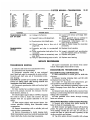
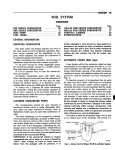
SERVICE PROCEDURES
SERVICE IN VEHICLE
Various transmission components c a n be removed
for repairs without removing the transmission f r o m
vehicle. T h e removal, reconditioning and installation
procedures f o r these components are covered here,
e x c e p t v a l v e body r e c o n d i t i o n i n g , w h i c h i s d e s c r i b e d
o n P a g e 34.
ALUMINUM THREAD
REPAIR
Damaged or worn threads i n the aluminum transm i s s i o n case a n d v a l v e body c a n b e r e p a i r e d b y t h e
u s e of H e l i - C o i l s . E s s e n t i a l l y , this r e p a i r consists of
d r i l l i n g out the w o r n o r d a m a g e d t h r e a d s , t a p p i n g the
hole w i t h a s p e c i a l H e l i - C o i l T a p , a n d i n s t a l l i n g a
H e l i - C o i l I n s e r t into the t a p p e d hole. T h i s b r i n g s t h e
TORQUEFLITE—TRANSMISSION
Heli-Coil Insert
Thread
Size
Part
No.
Insert
Length
10-24
1/4-20
5/16-18
3/8-16
7/16-14
1185-3
1185-4
1185-5
1185-6
1185-7
.285"
3/8"
15/32"
9/16"
21/32"
21-19
Drill
Tap
Inserting
Tool
Extracting
Tool
Size
Part
No.
Part
No.
Part
No.
528-3N
528-4N
528-5N
528-6N
528-7N
1227-6
1227-6
1227-6
1227-6
1227-16
13/64"
17/64"
Q
X
29/32"
hole b a c k to its o r i g i n a l t h r e a d size.
T h e c h a r t lists t h e t h r e a d e d hole sizes w h i c h a r e
u s e d i n the a l u m i n u m case a n d v a l v e body, a n d t h e
n e c e s s a r y tools a n d i n s e r t s f o r the r e p a i r of d a m a g e d
or w o r n t h r e a d s . H e l i - C o i l tools a n d i n s e r t s a r e r e a d i l y available f r o m m o s t automotive parts j o b b e r s .
Some thread drag may occur in screwing a bolt into
the installed Heli-Coil insert. Therefore, a torque
reading should be taken of the thread drag with an
inch-pound torque wrench and added to the specified
bolt torque, so that all bolts securing a particular part
will be tightened to the same torque.
LUBRICATION
T h e t r a n s m i s s i o n fluid a n d filter s h o u l d p r o v i d e
satisfactory l u b r i c a t i o n a n d protection to t h e automatic transmission a n d no change is recommended i n
vehicles used i n normal service. Regularly scheduled
fluid a n d filter c h a n g e s , t h e r e f o r e w i l l not b e r e q u i r e d , except w h e n t h e operation of the v e h i c l e i s
classified as s e v e r e .
If, f o r a n y r e a s o n , t h e f a c t o r y fill fluid i s r e p l a c e d
w i t h another fluid, t h e fluid m u s t b e c h a n g e d e v e r y
t h r e e y e a r s o r 36,000 m i l e s i n n o r m a l service.
F l u i d Level
I n s p e c t fluid l e v e l e v e r y s i x m o n t h s w i t h e n g i n e
a n d t r a n s m i s s i o n at n o r m a l o p e r a t i n g t e m p e r a t u r e .
R e f e r to " L u b r i c a t i o n a n d M a i n t e n a n c e " , G r o u p 0.
T h e t r a n s m i s s i o n s h o u l d not b e i d l e d i n gear f o r l o n g
periods.
Trailer
Towing
Service
and Hard
Usage
If v e h i c l e i s u s e d f o r t r a i l e r t o w i n g o r i s u s e d i n
hard or severe service, more frequent servicing is req u i r e d as outlined.
D r a i n a n d r e f i l l t r a n s m i s s i o n a n d r e p l a c e filter
i n i t i a l l y at 36,000 m i l e s o r 3 y e a r s a n d e v e r y 12,000
m i l e s o r 12 m o n t h s thereafter.
Drain and
Refill
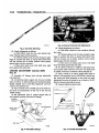
(1) R a i s e v e h i c l e o n a hoist. P l a c e a d r a i n c o n t a i n e r
with a large opening, under the transmission oil p a n .
(2) L o o s e n p a n bolts, tap p a n to b r e a k it loose a l l o w i n g fluid to d r a i n , t h e n r e m o v e t h e o i l p a n .
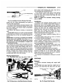
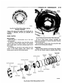
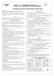
(3) R e m o v e a c c e s s plate f r o m i n f r o n t of c o n v e r t e r ,
r e m o v e d r a i n p l u g a l l o w i n g t h e fluid to d r a i n ( F i g . 2).
(.203")
(.265")
(.332")
(.397")
(.453")
3
4
5
6
7
CPB
CPB
CPB
CPB
CPB
I n s t a l l a n d tighten c o n v e r t e r d r a i n p l u g to 110 i n c h p o u n d s , a n d i n s t a l l t h e access plate.
(4) I f n e c e s s a r y , a d j u s t t h e r e v e r s e b a n d .
(5) I n s t a l l a n e w filter o n bottom of t h e v a l v e body,
a n d tighten r e t a i n i n g s c r e w s to 3 5 i n c h - p o u n d s .
(6) C l e a n t h e o i l p a n , a n d r e i n s t a l l u s i n g a n e w
g a s k e t . T i g h t e n p a n bolts to 150 i n c h - p o u n d s .
(7) P o u r s i x q u a r t s of A u t o m a t i c T r a n s m i s s i o n
F l u i d , A Q - A T F Suffix " A " (Dexron) into t h e t r a n s m i s sion.
(8) S t a r t e n g i n e a n d allow to idle f o r at l e a s t two
minutes. W i t h parking brake on, move selector lever
m o m e n t a r i l y to e a c h position e n d i n g i n the n e u t r a l
position.
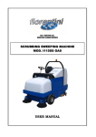
(9) A d d sufficient fluid to b r i n g fluid l e v e l to the
" A D D O N E P I N T " mark.
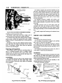
(10) R e c h e c k fluid l e v e l a f t e r t r a n s m i s s i o n i s at
n o r m a l o p e r a t i n g t e m p e r a t u r e . T h e l e v e l s h o u l d be
between the " F U L L " m a r k and " A D D O N E P I N T "
m a r k ( F i g . 3).
C A U T I O N : To prevent dirt from entering transmission, make certain that dip stick cap is fully seated
onto the filler tube.
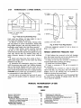
G E A R S H I F T LINKAGE ADJUSTMENT
(Column Shift) (Fig. 4)
(1) A s s e m b l e a l l l i n k a g e p a r t s l e a v i n g a d j u s t a b l e
r o d e n d free.
(2) P l a c e g e a r s h i f t selector l e v e r i n P A R K position
a n d l o c k s t e e r i n g c o l u m n w i t h ignition k e y .
(3) Move shift c o n t r o l l e v e r o n t r a n s m i s s i o n a l l the
w a y to r e a r (in P A R K detent) ( F i g . 5).
(4) S e t a d j u s t a b l e r o d to p r o p e r l e n g t h a n d i n s t a l l
w i t h n o l o a d i n e i t h e r direction on linkage.
Fig. 2—Converter Drain Mug
21-20
A
TRANSMISSION—TORQUEFLITE
ND167A
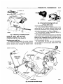
Fig. 3—Dip Stick
Markings
Fig. 5—External Controls and
Mdimtments
(5) C h e c k a d j u s t m e n t as follows:
(5) C h e c k A d j u s t m e n t a s follows:
(a) S h i f t effort m u s t be f r e e a n d detents f e e l
c r i s p . A l l gate stops m u s t be positive.
(b) D e t e n t position m u s t be close e n o u g h to gate
stops i n n e u t r a l a n d d r i v e to a s s u r e that h a n d l e v e r
w i l l not r e m a i n out of detent position w h e n p l a c e d
against gate a n d t h e n r e l e a s e d .
(c) K e y s t a r t m u s t o c c u r w i t h shift l e v e r h e l d
d o w n against the p a r k gate.
(a) S h i f t effort s h o u l d be f r e e e n o u g h so detents
feel crisp.
(b) D e t e n t position m u s t be close e n o u g h to gate
stops i n n e u t r a l a n d d r i v e to a s s u r e that h a n d l e v e r
w i l l not r e m a i n out of detent position w h e n p l a c e d
against gate a n d t h e n r e l e a s e d .
(c) K e y start a n d l o c k i n g m u s t o c c u r w i t h shift
l e v e r h e l d b a c k against the p a r k gate.
(6) If console r e m o v a l i s r e q u i r e d , d i s c o n n e c t batt e r y g r o u n d c a b l e . R e m o v e set s c r e w a n d shift k n o b
L I N K A G E A D J U S T M E N T (Console Shift)
(Fig. 8)
o r h a n d l e . P r o c e e d as outlined i n B o d y S e c t i o n 23.
(7) A f t e r console i s i n p l a c e , i n s t a l l shift k n o b as
(1) A s s e m b l e a l l l i n k a g e p a r t s l e a v i n g a d j u s t a b l e
rod ends free.
follows: w i t h g e a r s h i p l e v e r h i N E U T R A L , t h r e a d button, s p r i n g a n d k n o b a s s e m b l y on the cable e n d u n t i l
(2) A t s t e e r i n g c o l u m n u p p e r e n d , l i n e u p l o c a t i n g
slots i n bottom of shift h o u s i n g a n d b e a r i n g h o u s i n g .
I n s t a l l suitable tool to h o l d this a l i g n m e n t a n d l o c k
d i m e n s i o n f r o m top of button to top of k n o b i s 1 3 / 3 2 "
( F i g . 6). S e c u r e k n o b w i t h set s c r e w .
(8) C o n n e c t battery g r o u n d cable.
c o l u m n w i t h ignition k e y .
(3) P l a c e c o n s o l e l e v e r i n P A R K a n d m o v e shift cont r o l l e v e r on t r a n s m i s s i o n a l l the w a y to the r e a r (in
P A R K detent).
(4) S e t a d j u s t a b l e r o d s to p r o p e r l e n g t h w i t h no
l o a d a p p l i e d i n e i t h e r d i r e c t i o n on l i n k a g e .
PY228
Fig. 4—Gearshift
Linkage
Fig. 6—Console Gearshift
Unit
21-21
TORQUEFLITE—TRANSMISSION
A,
SCREWS (2)
CONTACT
SEAL
SCREWS (4)
WIRING
CONNECTOR
SWITCH
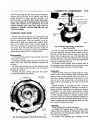
NU450
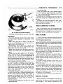
Fig. 9—Nevtral-Park Starting Switch and
Back-Up Light Switch
c a m i n only Park a n d Neutral positions.
(1) T o test s w i t c h , r e m o v e w i r i n g c o n n e c t o r f r o m
s w i t c h a n d test f o r continuity b e t w e e n c e n t e r p i n of
s w i t c h a n d t r a n s m i s s i o n case. C o n t i n u i t y s h o u l d exist
only w h e n t r a n s m i s s i o n i s i n Park o r Neutral.
NN564C
Fig. 7—Removing or Installing
Console
BACK-UP LIGHT AND NEUTRAL
STARTING SWITCH (Fig. 9 and 10)
Replacement a n d Test
T h e Neutral Starting Switch is the center terminal
of t h e 3 t e r m i n a l s w i t c h . I t p r o v i d e s g r o u n d f o r t h e
starter solenoid circuit through the selector lever
(2) C h e c k g e a r s h i f t l i n k a g e a d j u s t m e n t b e f o r e r e p l a c i n g a s w i t c h w h i c h tests b a d .
(3) U n s c r e w s w i t c h f r o m t r a n s m i s s i o n c a s e a l l o w i n g
fluid to d r a i n into a c o n t a i n e r . Move s e l e c t o r l e v e r to
Park a n d t h e n to Neutral positions, a n d i n s p e c t to s e e
that t h e s w i t c h operating l e v e r fingers a r e c e n t e r e d
in switch opening i n the case.
(4) S c r e w s w i t c h a n d n e w s e a l into t r a n s m i s s i o n
case a n d tighten to 24 foot-pounds. R e t e s t s w i t c h w i t h
the test l a m p .
STEERING COLUMN
LOWER ROD
Fig* i—Console Gearshift
PY231
Linkage
TRANSMISSION—TORQUEFLITE
21-22
•A
If a d a p t e r C-3705 i s n o t u s e d , tighten a d j u s t i n g s c r e w
to 72 i n c h - p o u n d s .
(4) B a c k off a d j u s t i n g s c r e w 2 t u r n s . H o l d a d j u s t i n g s c r e w i n t h i s position a n d tighten l o c k n u t to 3 5
foot-pounds.
(5) R e i n s t a l l o i l p a n u s i n g a n e w gasket. T i g h t e n o i l
p a n bolts to 150 i n c h - p o u n d s .
(6) F i l l t r a n s m i s s i o n w i t h " A u t o m a t i c T r a n s m i s s i o n
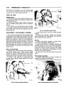
F l u i d A Q - A T F Suffix A , ( D e x r o n ) .
THOTTLE ROD ADJUSTMENT (Fig. 11)
W i t h e n g i n e at operating t e m p e r a t u r e a n d c a r b u r e t o r off fast idle c a m , a d j u s t idle s p e e d of e n g i n e
u s i n g a t a c h o m e t e r . R e f e r to " F u e l S y s t e m " G r o u p
14, f o r idle s p e e d Specifications a n d c a r b u r e t o r linkage a d j u s t m e n t .
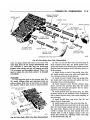
Fig. I©—Bottom View of Transmission
(Pan Removed)
(5) A d d fluid to t r a n s m i s s i o n to b r i n g u p to p r o p e r
level.
(6) T h e B a c k - U p L i g h t S w i t c h C i r c u i t i s t h r o u g h t h e
two outside t e r m i n a l s of t h e 3 t e r m i n a l s w i t c h .
(7) T o test s w i t c h , r e m o v e w i r i n g c o n n e c t o r f r o m
s w i t c h a n d test f o r continuity b e t w e e n t h e t w o outside
pins.
(8) C o n t i n u i t y s h o u l d e x i s t only w i t h t r a n s m i s s i o n
i n R e v e r s e position.
(9) N o continuity s h o u l d e x i s t f r o m e i t h e r p i n to
the case.
BAND ADJUSTMENTS
Kickdown
Band
T h e kickdown band adjusting screw i s located on
left side of t r a n s m i s s i o n c a s e n e a r t h e t h r o t t l e l e v e r
shaft ( F i g . 5).
(1) L o o s e n l o c k n u t a n d b a c k off a p p r o x i m a t e l y five
turns. Inspect adjusting screw for free turning i n the
t r a n s m i s s i o n case.
(2) U s i n g w r e n c h , T o o l C-3380 w i t h a d a p t e r C - 3 7 0 5 ,
tighten b a n d a d j u s t i n g s c r e w 4 7 to 50 i n c h - p o u n d s . I f
a d a p t e r C-3705 i s n o t u s e d , t i g h t e n a d j u s t i n g s c r e w to
72 i n c h - p o u n d s w h i c h i s t h e t r u e t o r q u e .
(3) B a c k off a d j u s t i n g s c r e w 2 t u r n s . H o l d a d j u s t i n g s c r e w i n t h i s position a n d t i g h t e n l o c k n u t to 2 9
foot-pounds.
Low and Reverse
Band
(1) R a i s e v e h i c l e , d r a i n t r a n s m i s s i o n fluid a n d r e move oil pan.
(2) L o o s e n a d j u s t i n g s c r e w l o c k n u t a n d b a c k off
n u t a p p r o x i m a t e l y five t u r n s ( F i g . 10). I n s p e c t a d j u s t ing screw for free turning i n the lever.
(3) U s i n g w r e n c h , T o o l C-3380 w i t h a d a p t e r C - 3 7 0 5 ,
tighten b a n d a d j u s t i n g s c r e w to 4 7 to 50 i n c h - p o u n d s .
(1) F o l l o w detailed i n s t r u c t i o n s i n L u b r i c a t i o n S e c tion f o r l i n k a g e l u b r i c a t i o n of a l l m o d e l s .
(2) D i s c o n n e c t c h o k e at c a r b u r e t o r o r block c h o k e
v a l v e i n f u l l open position. O p e n throttle slightly to
r e l e a s e fast i d l e c a m , t h e n r e t u r n c a r b u r e t o r to c u r b
idle.
(3) L o o s e n t h e t r a n s m i s s i o n throttle r o d a d j u s t m e n t
lock s c r e w .
(4) H o l d t h e t r a n s m i s s i o n l e v e r f o r w a r d against i t s
stop w h i l e a d j u s t i n g the t r a n s m i s s i o n l i n k a g e . (On
e n g i n e s w i t h solenoid idle stops, the solenoid p l u n g e r
m u s t also b e i n its f u l l y e x t e n d e d position).
(5) A d j u s t t h e t r a n s m i s s i o n r o d b y p u l l i n g f o r w a r d
on the slotted l i n k w i t h a slight effort so that t h e r e a r
edge of the slot i s against t h e c a r b u r e t o r l e v e r p i n .
Tighten transmission rod adjustment locking screw.
Note: T h e slotted l i n k a n d t r a n s m i s s i o n l e v e r m u s t
be h e l d f o r w a r d w h i l e t h e l o c k i n g s c r e w i s b e i n g tightened.
(6) T o c h e c k t r a n s m i s s i o n l i n k a g e f r e e d o m of operation, m o v e slotted l i n k to the f u l l r e a r w a r d position,
t h e n allow it to r e t u r n slowly, m a k i n g s u r e it r e t u r n s
to t h e f u l l f o r w a r d position.
(7) L o o s e n c a r b u r e t o r cable c l a m p n u t . A d j u s t position of cable h o u s i n g f e r r u l e i n the c l a m p so that a l l
s l a c k i s r e m o v e d f r o m cable w i t h c a r b u r e t o r at c u r b
idle. T o r e m o v e s l a c k f r o m cable, move f e r r u l e i n t h e
clamp i n direction away from carburetor lever.
(8) B a c k off f e r r u l e 1 / 4 " . T h i s p r o v i d e s 1 / 4 " f r e e
play. T i g h t e n cable c l a m p n u t to 4 5 inch-pounds.
(9) C o n n e c t c h o k e r o d o r r e m o v e b l o c k i n g
fixture.
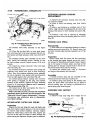
HYDRAULIC CONTROL P R E S S U R E T E S T S
Line Pressure
and Front
Release
Pressure
Servo
L i n e p r e s s u r e a n d f r o n t s e r v o r e l e a s e p r e s s u r e tests
m u s t b e m a d e i n D (drive) position w i t h r e a r w h e e l s
f r e e to t u r n . T h e t r a n s m i s s i o n fluid m u s t b e at operati n g t e m p e r a t u r e ( 1 5 0 ° F to 2 0 0 ° F ) .
TORQUEFLITE—TRANSMISSION
A.
Fig. I I - T h r o t t l e Rod
(1) I n s t a l l a n e n g i n e t a c h o m e t e r , r a i s e v e h i c l e on a
hoist a n d position t a c h o m e t e r so it c a n be r e a d u n d e r
the v e h i c l e .
(2) C o n n e c t two 0-100 p s i p r e s s u r e g a u g e s , T o o l C 3292 to p r e s s u r e take-off points at s i d e of a c c u m u lator a n d at front s e r v o r e l e a s e ( F i g . 12).
(3) W i t h c o n t r o l i n D (drive) position, s p e e d u p
e n g i n e s l i g h t l y u n t i l t r a n s m i s s i o n s h i f t s into
direct.
( F r o n t s e r v o r e l e a s e w i l l be p r e s s u r i z e d i n direct.) R e d u c e engine s p e e d s l o w l y to 1,000 r p m . L i n e p r e s s u r e
21-23
Adjustment
sion throttle lever for looseness on the valve body
shaft when making pressure tests.
Lubrication
Pressures
T h e l u b r i c a t i o n p r e s s u r e test s h o u l d be m a d e at
s a m e t i m e that l i n e p r e s s u r e a n d f r o n t s e r v o r e l e a s e
p r e s s u r e s a r e tested.
(1) I n s t a l l a " t e e " fitting b e t w e e n c o o l e r r e t u r n l i n e
fitting a n d fitting h o l e i n t r a n s m i s s i o n c a s e at r e a r
left side of the t r a n s m i s s i o n case ( F i g . 13). C o n n e c t a
at this time (1,000 r p m ) m u s t be 54-60 p s i , a n d f r o n t
s e r v o r e l e a s e p r e s s u r e m u s t not be m o r e t h a n 3 p s i
below l i n e p r e s s u r e .
(4) D i s c o n n e c t throttle l i n k a g e f r o m t r a n s m i s s i o n
throttle l e v e r a n d m o v e throttle l e v e r g r a d u a l l y to
full
throttle position. L i n e p r e s s u r e m u s t
rise
to
a m a x i m u m of 90-96 p s i j u s t b e f o r e o r at k i c k d o w n
into low gear. F r o n t s e r v o r e l e a s e p r e s s u r e m u s t follow l i n e p r e s s u r e u p to the k i c k d o w n point a n d s h o u l d
not be m o r e t h a n 3 p s i below l i n e p r e s s u r e .
I f l i n e p r e s s u r e i s not 54-60 p s i at 1,000 r p m , s e e
"Hydraulic Control Pressure Adjustments".
If f r o n t s e r v o r e l e a s e p r e s s u r e s a r e l e s s t h a n p r e s s u r e specified a n d l i n e p r e s s u r e s a r e w i t h i n
limits,
there is excessive leakage i n front clutch a n d / o r front
s e r v o c i r c u i t s . Always inspect the external transmis-
Fig. 12—Pressure Test Locations (Right Side of Case)
21-24
TRANSMISSION—TORQUEFLITE-
0-100 p s i p r e s s u r e gauge, T o o l C-3292 to t h e " t e e "
fitting.
(2) A t 1,000 e n g i n e r p m , w i t h throttle c l o s e d a n d
transmission i n direct, the lubrication pressure should
be 5-15 p s i . L u b r i c a t i o n p r e s s u r e w i l l b e a p p r o x i m a t e l y d o u b l e d a s throttle i s o p e n e d to the m a x i m u m l i n e
pressure.
R e a r S e r v o Apply
Pressure
(1) C o n n e c t a 0-300 p s i p r e s s u r e gauge, T o o l C-3293
to a p p l y p r e s s u r e take-off point at r e a r s e r v o ( F i g . 13).
(2) W i t h t r a n s m i s s i o n c o n t r o l i n R ( r e v e r s e ) position a n d e n g i n e s p e e d s e t at 1600 r p m , t h e r e v e r s e
s e r v o a p p l y p r e s s u r e s h o u l d be 230 to 300 p s i .
Throttle
Pressure
N o p r o v i s i o n s a r e m a d e to test t h e t h r o t t l e p r e s s u r e .
I n c o r r e c t throttle p r e s s u r e s h o u l d only b e s u s p e c t e d
if p a r t throttle shift s p e e d s a r e e i t h e r v e r y d e l a y e d
or o c c u r too e a r l y i n r e l a t i o n to v e h i c l e speeds. I n
w h i c h c a s e , t h e throttle l i n k a g e s h o u l d b e a d j u s t e d
before throttle p r e s s u r e setting i s a d j u s t e d .
HYDRAULIC CONTROL P R E S S U R E
ADJUSTMENTS
Pressure
Line
A n i n c o r r e c t throttle p r e s s u r e setting w i l l c a u s e i n c o r r e c t line p r e s s u r e r e a d i n g s e v e n t h o u g h l i n e p r e s s u r e a d j u s t m e n t i s c o r r e c t . A l w a y s i n s p e c t a n d cor-
Governor
Pressure
(1) C o n n e c t a 0-100 p s i p r e s s u r e gauge, T o o l C-3292
to g o v e r n o r p r e s s u r e take-off point, l o c a t e d at l o w e r
left s i d e of e x t e n s i o n n e a r t h e m o u n t i n g flange ( F i g .
13).
(2) G o v e r n o r p r e s s u r e s s h o u l d f a l l w i t h i n t h e l i m i t s
given i n the "Governor Pressure Chart."
I f g o v e r n o r p r e s s u r e s a r e i n c o r r e c t at t h e g i v e n
v e h i c l e speeds, t h e g o v e r n o r v a l v e a n d / o r w e i g h t s a r e
probably sticking.
distance between the manual valve (valve in 1-low
position) and line pressure adjusting screw (Fig. 14).
This measurement must be 1-7/8 inches; correct by
loosening spring retainer screws a n d repositioning the
spring retainer. The regulator valve may cock and
hang up in its bore if spring retainer is out of position.
If l i n e p r e s s u r e i s not c o r r e c t , it w i l l b e n e c e s s a r y
to r e m o v e v a l v e body a s s e m b l y to p e r f o r m t h e a d -
GOVERNOR PRESSURE CHART
Vehicle Speed To Axle Ratios
Chrysler
Imperial
2.76:1
3.23:1
2.94:1
r e c t throttle p r e s s u r e a d j u s t m e n t before a d j u s t i n g t h e
l i n e p r e s s u r e . Before adjusting line pressure, measure
justment.
Pressure
Limits*
psi
The
approximate
adjustment
is
1-5/16
inches,
m e a s u r e d f r o m v a l v e body to i n n e r edge of t h e adjusti n g n u t ( F i g . 15). H o w e v e r , d u e to m a n u f a c t u r i n g tole r a n c e s , the a d j u s t m e n t c a n b e v a r i e d to obtain speci-
20-22
48-57
77-85
17-19
41-49
66-73
19-22
48-57
77-85
15
50
75
* T h e governor p r e s s u r e should respond smoothly to
c h a n g e s in m.p.h. a n d s h o u l d return to 0 to 1-1/2 psi
w h e n the v e h i c l e is stopped. High p r e s s u r e a t s t a n d still (above 2 psi) will prevent the t r a n s m i s s i o n from
downshifting.
LUBRICATION
PRESSURE
(COOLER RETURN
FITTING)
fied l i n e p r e s s u r e .
T h e adjusting screw may be turned with an A l l e n
wrench.
One complete
turn
of
adjusting
screw
c h a n g e s c l o s e d throttle l i n e p r e s s u r e a p p r o x i m a t e l y
1-2/3 p s i . T u r n i n g a d j u s t i n g s c r e w c o u n t e r c l o c k w i s e
increases pressure, and clockwise decreases pressure.
Throttle
Throttle
Pressure
pressure cannot
be tested
accurately:
GOVERNOR
PRESSURE
REAR SERVO
APPLY
PRESSURE
NN71A
Fig. 13—Pressure Test Locations (Rear End of Case)
Fig. 14—Measuring Spring Retainer
Location
-TORQUEFLITE—TRANSMISSION
21-25
c o r r e c t fluid p r e s s u r e , b e c a u s e of i n o p e r a t i v e c l u t c h e s
or b a n d s . T h e i n o p e r a t i v e u n i t s , c l u t c h e s , b a n d s a n d
servos c a n be located through
a s e r i e s of tests b y
s u b s t i t u t i n g a i r p r e s s u r e f o r fluid p r e s s u r e ( F i g . 17).
The front a n d rear
clutches, kickdown
servo, a n d
l o w - r e v e r s e s e r v o m a y b e tested b y a p p l y i n g a i r p r e s s u r e to t h e i r r e s p e c t i v e p a s s a g e a f t e r v a l v e b o d y a s s e m b l y h a s b e e n r e m o v e d . T o m a k e a i r p r e s s u r e tests,
p r o c e e d a s follows:
C A U T I O N : Compressed air supply must be free of all
dirt or moisture. Use a pressure of 30 to 100 psi.
SB
Front
NN72A
Fig. 15—Lira© iprcssswr® Adjustment
therefore,
the adjustment
Clutch
A p p l y a i r p r e s s u r e to f r o n t c l u t c h " a p p l y " p a s s a g e
a n d l i s t e n f o r a d u l l " t h u d " w h i c h i n d i c a t e s that r e a r
should be measured if a
clutch i s operating. Hold a i r pressure on for a f e w
seconds a n d inspect system for excessive oil leaks.
m a l f u n c t i o n i s evident.
(1) Remove v a l v e body a s s e m b l y f r o m t r a n s m i s s i o n
Rear
to p e r f o r m a d j u s t m e n t .
(2) Loosen throttle l e v e r stop s c r e w l o c k n u t a n d
b a c k off a p p r o x i m a t e l y five t u r n s ( F i g . 16).
Clutch
A p p l y a i r p r e s s u r e to r e a r c l u t c h " a p p l y " p a s s a g e
a n d l i s t e n f o r a d u l l " t h u d " w h i c h i n d i c a t e s that r e a r
(3) I n s e r t gauge p i n of T o o l C-3763 b e t w e e n t h e
throttle l e v e r c a m a n d k i c k d o w n v a l v e .
clutch is operating. Also check f o r excessive oil leaks.
If a dull " t h u d " cannot be heard in clutches, place
(4) B y p u s h i n g i n o n t h e tool, c o m p r e s s k i c k d o w n
finger tips on clutch housing and again apply air
v a l v e against i t s s p r i n g so throttle v a l v e i s c o m p l e t e l y
pressure. Movement of piston can be felt as clutch is
bottomed i n s i d e t h e v a l v e body.
applied.
(5) A s f o r c e i s b e i n g e x e r t e d to c o m p r e s s s p r i n g ,
tighten throttle l e v e r stop s c r e w finger tight against
throttle l e v e r t a n g w i t h t h r o t t l e l e v e r c a m t o u c h i n g
Kickdown
Servo
D i r e c t a i r p r e s s u r e into f r o n t s e r v o " a p p l y "
pas-
the tool a n d t h e throttle v a l v e bottomed. Be sure ad-
sage. O p e r a t i o n of s e r v o i s i n d i c a t e d b y a t i g h t e n i n g
justment is made with spring fully compressed and
of t h e f r o n t b a n d . S p r i n g t e n s i o n o n s e r v o
valve bottomed in the valve body.
should release the band.
(6) R e m o v e tool a n d t i g h t e n stop s c r e w l o c k n u t
L IN E PRESSURE T O A C C U M U L A T O R ^ ^ ^ ,
F
R
?
N
T
S
E
R
piston
^ °
securely.
FRONT SERVO
AIR P R E S S U R E T E S T S
A
" N O D R I V E " condition
RELEASE
•
might exist even with
| PUMP
< AUCTION
:f-1-
/ ^ T O O L
.
PUMP
KICKDOWN
\
PRESSURE
I'
- VALVE
FRONT
CLUTCH
' APPLY
*
PEAR
J
APPLY
LOCK
NUT
' J TO
CLUTCH
TORQUE
•••••
CONVERTER
THROTTLE
LEVER
FROM
STOP
SCREW
NN73A
£'%
0
ITftreffffi/© \Pv®mure Adjustment
TORQUE
CONVERTER
ND8A
W
T O COOLER -><
Fig. 17—Air Pressure
Tests
21-26
.A
TRANSMISSION—TORQUEFLITE
Low and Reverse
Servo
D i r e c t a i r p r e s s u r e into s e r v o " a p p l y " passage.
O p e r a t i o n of s e r v o i s i n d i c a t e d b y a t i g h t e n i n g of t h e
r e a r b a n d . S p r i n g t e n s i o n o n s e r v o piston s h o u l d r e lease the band.
I f c l u t c h e s a n d s e r v o s operate p r o p e r l y ; no u p s h i f t
or e r r a t i c shift c o n d i t i o n s i n d i c a t e that m a l f u n c t i o n
e x i s t s i n the v a l v e body.
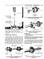
SPEEDOMETER
• RETAINER
RING
PINION
BOLT A N D
WASHER
NN362
PINION
Removal
and
Installation
R e a r a x l e g e a r ratio a n d t i r e size d e t e r m i n e s p i n i o n
g e a r size r e q u i r e m e n t s . R e f e r to ' S p e e d o m e t e r P i n i o n
C h a r t ' i n Specifications f o r p i n i o n u s a g e .
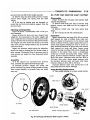
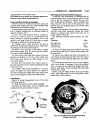
(1) R e m o v e bolt a n d r e t a i n e r s e c u r i n g s p e e d o m e t e r
p i n i o n a d a p t e r i n t h e e x t e n s i o n h o u s i n g ( F i g . 18).
(2) W i t h c a b l e h o u s i n g c o n n e c t e d , c a r e f u l l y w o r k
a d a p t e r a n d p i n i o n out of t h e e x t e n s i o n h o u s i n g .
(3) I f t r a n s m i s s i o n fluid i s f o u n d i n c a b l e h o u s i n g ,
r e p l a c e s e a l i n t h e a d a p t e r ( F i g . 19). S t a r t s e a l a n d
r e t a i n e r r i n g i n t h e a d a p t e r , t h e n p u s h t h e m into
a d a p t e r w i t h T o o l C-4004 u n t i l tool bottoms ( F i g .
20).
C A U T I O N : Before installing pinion and adapter assembly make sure adapter flange and its mating area
on extension housing are perfectly clean. Dirt or sand
will cause mis-alignment resulting in speedometer
pinion gear noise.
(4) N o t e n u m b e r of g e a r teeth a n d i n s t a l l s p e e d o m e t e r p i n i o n g e a r into a d a p t e r ( F i g . 19).
(5) R o t a t e t h e s p e e d o m e t e r p i n i o n gear a n d a d a p t e r
a s s e m b l y so t h a t the n u m b e r on t h e adapter, c o r r e s p o n d i n g to t h e n u m b e r of t e e t h on the gear, i s i n t h e
6 o'clock position as t h e a s s e m b l y i s i n s t a l l e d ( F i g . 18).
(6) I n s t a l l r e t a i n e r a n d bolt, w i t h r e t a i n e r tangs i n
a d a p t e r positioning slots. T a p adapter firmly into t h e
e x t e n s i o n h o u s i n g a n d tighten r e t a i n e r bolt to 100
inch-pounds.
ADAPTER
OIL SEAL
RETAINER
RING
Fig. 19—Speedometer
y o k e out of
CAUTION:
surface on
installation
Drive
transmission extension housing.
Be careful not to scratch or nick ground
sliding spline yoke during removal and
of the shaft assembly.
(2) R e m o v e t h e e x t e n s i o n h o u s i n g y o k e s e a l ( F i g .
21) w i t h T o o l C-3985.
(3) T o i n s t a l l a n e w s e a l , position s e a l i n o p e n i n g of
e x t e n s i o n h o u s i n g a n d d r i v e it into h o u s i n g w i t h T o o l
C-3972 ( F i g . 22).
(4) C a r e f u l l y guide f r o n t u n i v e r s a l j o i n t y o k e into
e x t e n s i o n h o u s i n g a n d o n t h e output s h a f t s p l i n e s .
A l i g n m a r k s m a d e at r e m o v a l a n d c o n n e c t p r o p e l l e r
shaft to r e a r axle p i n i o n shaft y o k e .
EXTENSION HOUSING AND OUTPUT
SHAFT BEARING
Removal
(1) M a r k p a r t s f o r r e a s s e m b l y t h e n d i s c o n n e c t prop e l l e r shaft at r e a r u n i v e r s a l joint. C a r e f u l l y p u l l shaft
a s s e m b l y out of the e x t e n s i o n h o u s i n g .
(2) R e m o v e s p e e d o m e t e r p i n i o n a n d a d a p t e r a s ADAPTER
LOCK
RING
EXTENSION HOUSING YOKE S E A L
Replacement
(1) M a r k p a r t s f o r r e a s s e m b l y t h e n d i s c o n n e c t prop e l l e r shaft at r e a r u n i v e r s a l joint. C a r e f u l l y p u l l shaft
TOOL
SEAL
NP2
Fig. 20—Installing Speedometer
Pinion
Seal
TOOL
\
SEAL
ADAPTER
- 6 O'CLOCK POSITION
NN74A
Fig. I8—Speedometer Pinion and AdapterInstalled (Retainer Removed for View)
H
NN36J
Fig. 21—Removing Extension
Housing Yoke
Seal
A.
-TORQUEFLITE—TRANSMISSION
m o v e output shaft b e a r i n g r e a r s n a p r i n g a n d rem o v e b e a r i n g f r o m the shaft ( F i g . 24).
'TOOL
•*8$jr •
• r * £ ? " -*S0">-
•
•
—
(2) I f r e m o v e d , i n s t a l l s n a p r i n g i n f r o n t groove
o n output shaft. I n s t a l l a n e w b e a r i n g on s h a f t w i t h
o u t e r r a c e r i n g groove t o w a r d f r o n t ( F i g . 24), t h e n
install rear snap ring.
NN125
Fig. 22—installing Extension Housing Yoke Semi
s e m b l y ( F i g . 18). D r a i n a p p r o x i m a t e l y two q u a r t s of
fluid f r o m the t r a n s m i s s i o n .
(3) R e m o v e bolts s e c u r i n g e x t e n s i o n h o u s i n g to the
c r o s s m e m b e r . R a i s e t r a n s m i s s i o n slightly w i t h s e r v i c e
jack Tool C-3203A, then remove center crossmember
and support assembly.
(4) R e m o v e the e x t e n s i o n h o u s i n g to t r a n s m i s s i o n
bolts.
C o n s o l e S h i f t : R e m o v e two bolts s e c u r i n g g e a r s h i f t
torque shaft l o w e r b r a c k e t to the e x t e n s i o n h o u s i n g .
S w i n g b r a c k e t out of w a y for e x t e n s i o n h o u s i n g removal.
I M P O R T A N T : In r e m o v i n g o r installing t h e e x t e n s i o n
h o u s i n g (step 5), the g e a r s h i f t l e v e r m u s t in in
"V
(low) position. T h i s positions the p a r k i n g lock control
rod r e a r w a r d so it c a n be d i s e n g a g e d or engaged w i t h
the p a r k i n g lock s p r a g .
(5) R e m o v e two s c r e w s , plate a n d gasket f r o m bott o m of e x t e n s i o n h o u s i n g m o u n t i n g pad. S p r e a d l a r g e
s n a p r i n g f r o m output shaft b e a r i n g w i t h T o o l C 3 3 0 1 A ( F i g . 23). W i t h s n a p r i n g s p r e a d as f a r as possible, c a r e f u l l y tap e x t e n s i o n h o u s i n g off output s h a f t
bearing. Carefully pull extension housing rearward,
to r e m o v e p a r k i n g l o c k c o n t r o l r o d k n o b p a s t t h e
p a r k i n g s p r a g , t h e n r e m o v e the h o u s i n g .
Bearing
21-27
Replacement
N O T E : T o r e p l a c e the
refer to I N D E X .
extension housing bushing,
Installation
(1) P l a c e a n e w e x t e n s i o n h o u s i n g g a s k e t o n the
t r a n s m i s s i o n case. P o s i t i o n output shaft b e a r i n g ret a i n i n g s n a p r i n g i n the e x t e n s i o n h o u s i n g . S l i d e ext e n s i o n h o u s i n g o n output shaft g u i d i n g p a r k i n g l o c k
c o n t r o l r o d k n o b past the p a r k i n g s p r a g . W h i l e
spreading large snap ring in housing with Tool C3 3 0 1 A ( F i g . 23), c a r e f u l l y tap h o u s i n g into p l a c e ,
then release snap ring. Make sure snap ring is fully
s e a t e d i n b e a r i n g outer r a c e r i n g groove.
(2) I n s t a l l a n d tighten e x t e n s i o n h o u s i n g bolts to
2 4 foot-pounds.
(3) I n s t a l l gasket, plate a n d two s c r e w s o n bottom
of e x t e n s i o n h o u s i n g m o u n t i n g p a d .
(4) I n s t a l l c e n t e r c r o s s m e m b e r a n d r e a r m o u n t ass e m b l y , tighten r e t a i n i n g bolts to 75 foot-pounds.
L o w e r t r a n s m i s s i o n , i n s t a l l e x t e n s i o n h o u s i n g to supp o r t bolts a n d tighten to 40 foot-pounds.
C o n s o l e Shift: A l i g n g e a r s h i f t torque s h a f t l o w e r
b r a c k e t w i t h t h e e x t e n s i o n h o u s i n g . I n s t a l l t h e two
r e t a i n i n g bolts a n d tighten s e c u r e l y .
(5) I n s t a l l the s p e e d o m e t e r p i n i o n a n d a d a p t e r .
(6) C a r e f u l l y guide f r o n t u n i v e r s a l j o i n t y o k e into
e x t e n s i o n h o u s i n g a n d o n the output s h a f t s p l i n e s .
A l i g n m a r k s m a d e at r e m o v a l a n d c o n n e c t p r o p e l l e r
s h a f t to the r e a r a x l e p i n i o n shaft y o k e .
(7) A d d fluid to t r a n s m i s s i o n to b r i n g u p to p r o p e r
level.
(1) U s i n g h e a v y d u t y s n a p r i n g p l i e r s C-4020, r e •w
111
SNAP RING PLIERS
GOVERNOR
Removal
(1) R e m o v e e x t e n s i o n h o u s i n g a n d
output
shaft
bearing.
(2) C a r e f u l l y p r y
snap ring from weight
end
of
g o v e r n o r v a l v e s h a f t ( F i g . 25). S l i d e v a l v e a n d s h a f t
BEARING SNAP RING
GROOVE
NN76
Fig. 23—Removing or Installing Extension
Housing
NN119A
REAR
SNAP
RING
FRONT SNAP
RING
CONTROL ROD
Fig. 24—Output Shaft
Bearing
*
A
21-28
ISSION—TORQUEFLITEG O V E R N O R SUPPORT
A r D PARKING GEAR
(2) P o s i t i o n s u p p o r t a n d g o v e r n o r a s s e m b l y o n output shaft. A l i g n a s s e m b l y so g o v e r n o r v a l v e shaft hole
in g o v e r n o r body aligns w i t h hole i n t h e output shaft,
t h e n s l i d e a s s e m b l y into p l a c e . I n s t a l l s n a p r i n g be-
SNAP RING
h i n d g o v e r n o r body ( F i g . 25). T i g h t e n body to s u p p o r t
bolts to 100 i n c h - p o u n d s . B e n d e n d s of l o c k s t r a p s
o v e r t h e bolt h e a d s .
(3) A s s e m b l e g o v e r n o r
weights
a n d spring, a n d
secure with snap r i n g inside large governor weight.
P l a c e w e i g h t a s s e m b l y i n g o v e r n o r body a n d i n s t a l l
• GOVERNOR
snap r i n g .
BODY
(4) P l a c e g o v e r n o r v a l v e o n v a l v e shaft, i n s e r t t h e
a s s e m b l y into body a n d t h r o u g h g o v e r n o r w e i g h t s .
• BOLTS 14)
I n s t a l l v a l v e shaft r e t a i n i n g s n a p r i n g . I n s p e c t v a l v e
LOC<
a n d w e i g h t a s s e m b l y f o r f r e e m o v e m e n t after i n s t a l l a -
STRAPS
NN77
Governor Shaft and Weight Snap Rings
i?actio
tion.
(5) I n s t a l l output shaft b e a r i n g a n d e x t e n s i o n housing.
a s s e m b l y out of t h e g o v e r n o r body.
(3) R e m o v e l a r g e s n a p r i n g f r o m w e i g h t e n d of
g o v e r n o r body, lift out g o v e r n o r w e i g h t a s s e m b l y .
(4) R e m o v e s n a p r i n g f r o m i n s i d e g o v e r n o r w e i g h t ,
r e m o v e i n n e r w e i g h t a n d s p r i n g f r o m outer weight.
F i g u r e 2 6 s h o w s a d i s a s s e m b l e d v i e w of t h e g o v e r n o r
assembly.
(5) R e m o v e s n a p r i n g f r o m b e h i n d g o v e r n o r body,
t h e n slide body a n d s u p p o r t a s s e m b l y off t h e output
shaft. I f n e c e s s a r y , r e m o v e f o u r bolts a n d s e p a r a t e
governor from the support.
Cleaning
and
Inspection
PARKING LOCK COMPONENTS
Removal
(1) R e m o v e t h e e x t e n s i o n h o u s i n g .
(2) T o r e p l a c e t h e g o v e r n o r s u p p o r t a n d p a r k i n g
gear, r e f e r to " g o v e r n o r a n d s u p p o r t " .
(3) S l i d e shaft o u t of e x t e n s i o n h o u s i n g to r e m o v e
the p a r k i n g s p r a g a n d s p r i n g ( F i g . 27). R e m o v e s n a p
r i n g a n d slide r e a c t i o n p l u g a n d p i n a s s e m b l y o u t of
+1no In n i l
itkix*
c l Y* rt
i i u moi.ii .
(4) T o r e p l a c e t h e p a r k i n g l o c k c o n t r o l r o d , r e f e r to
T h e p r i m a r y c a u s e of g o v e r n o r o p e r a t i n g f a i l u r e i s
d u e to a s t i c k i n g g o v e r n o r v a l v e o r w e i g h t s . R o u g h
s u r f a c e s m a y b e r e m o v e d w i t h c r o c u s cloth. T h o r oughly c l e a n a l l p a r t s i n c l e a n s o l v e n t a n d i n s p e c t f o r
free movement before assembly.
Installation
Installation
t o w a r d t h e p a r k i n g gear, a n d s p r i n g i s positioned so it
(1) A s s e m b l e g o v e r n o r body to t h e s u p p o r t (if disa s s e m b l e d ) a n d t i g h t e n t h e bolts finger tight. M a k e
s u r e o i l passage of g o v e r n o r body a l i g n s w i t h p a s s a g e
(1) P o s i t i o n s p r a g a n d s p r i n g i n h o u s i n g a n d i n s e r t
the shaft ( F i g . 27). M a k e s u r e s q u a r e l u g o n s p r a g i s
m o v e s s p r a g a w a y f r o m t h e gear.
(2) I n s t a l l r e a c t i o n p l u g a n d p i n a s s e m b l y i n t h e
housing and secure with snap ring.
(3) I n s t a l l e x t e n s i o n h o u s i n g .
i n t h e support.
I
"Valve B o d y — R e m o v a l and Installation."
SPRING
BODY
SNAP
VALVE
RINGS
INNER
WEIGHT
SHAFT
VALVE
SPRING
SPRING
'SNAP RING
PLUG AND PIN
SNAP
Fig. 26—Governor
RING-
Assembly
CONTROL ROD
Fig. 27—Parking Lock
Components
NN78B
-TORQUEFLITE—TRANSMISSION
21-29
VALVE BODY A S S E M B L Y AND ACCUMULATOR
PISTON
15/16' SOCKET
Removal
(1) R a i s e the v e h i c l e on a hoist.
(2) L o o s e n oil p a n bolts, tap p a n to b r e a k it loose
a l l o w i n g fluid to d r a i n , t h e n r e m o v e the o i l p a n .
(3) D i s c o n n e c t throttle a n d g e a r s h i f t l i n k a g e f r o m
l e v e r s o n the t r a n s m i s s i o n . L o o s e n c l a m p bolts a n d
r e m o v e the l e v e r s ( F i g . 5).
(4) R e m o v e E - c l i p ( F i g . 28), s e c u r i n g p a r k i n g l o c k
r o d to the v a l v e body m a n u a l l e v e r .
(5) R e m o v e B a c k - U p L i g h t a n d N e u t r a l S t a r t S w i t c h .
NN127
(6) P l a c e a d r a i n p a n u n d e r t r a n s m i s s i o n , t h e n r e m o v e the t e n h e x - h e a d v a l v e body to t r a n s m i s s i o n
case bolts. H o l d v a l v e body i n position w h i l e r e m o v i n g
the bolts.
Fig. 29—Installing Valve Body Manual Lever
Oil Seal
Shaft
k n o b o n e n d of
m o v e d , i n s e r t it t h r o u g h the o p e n i n g i n r e a r of case
w i t h k n o b positioned against the r e a c t i o n p l u g a n d
s p r a g . Move f r o n t e n d of r o d t o w a r d c e n t e r of transm i s s i o n w h i l e e x e r t i n g r e a r w a r d p r e s s u r e on the r o d
to f o r c e it past the s p r a g . (Rotate p r o p e l l e r shaft if
necessary.)
a c c u m u l a t o r piston f r o m t r a n s m i s -
(2) I n s t a l l a c c u m u l a t o r p i s t o n i n t h e t r a n s m i s s i o n
case.
s i o n case. I n s p e c t piston f o r s c o r i n g , a n d r i n g s for
(3) P o s i t i o n a c c u m u l a t o r s p r i n g o n the v a l v e body.
(7) W h i l e l o w e r i n g v a l v e body out of t r a n s m i s s i o n
case, disconnect parking lock rod f r o m the lever.
T o r e m o v e p a r k i n g l o c k r o d , p u l l it f o r w a r d out of
the case. I f n e c e s s a r y , rotate p r o p e l l e r s h a f t to a l i g n
p a r k i n g g e a r a n d s p r a g to p e r m i t
c o n t r o l r o d to p a s s the s p r a g .
(8) W i t h d r a w
w e a r or b r e a k a g e . R e p l a c e as r e q u i r e d .
(9) If v a l v e body m a n u a l l e v e r s h a f t s e a l r e q u i r e s
r e p l a c e m e n t , d r i v e it out of the case w i t h a p u n c h .
(10) D r i v e a n e w s e a l into the case w i t h a
15/16
i n c h s o c k e t a n d h a m m e r ( F i g . 29). Servicing the valve
body assembly is outlined under ''Recondition—SubAssemblies/'
Installation
(1) M a k e s u r e B a c k - U p L i g h t
and Neutral
Start
S w i t c h h a s b e e n r e m o v e d . If p a r k i n g l o c k r o d w a s re-
•43
(4) P l a c e the v a l v e body m a n u a l l e v e r i n LOW position. L i f t v a l v e body into its a p p r o x i m a t e position,
c o n n e c t p a r k i n g l o c k r o d to m a n u a l l e v e r a n d s e c u r e
w i t h the E - c l i p . P o s i t i o n v a l v e b o d y i n the c a s e , i n s t a l l
r e t a i n i n g bolts finger tight.
(5) W i t h n e u t r a l s t a r t i n g s w i t c h i n s t a l l e d , p l a c e
m a n u a l v a l v e i n the n e u t r a l position. S h i f t v a l v e body
if n e c e s s a r y to c e n t e r n e u t r a l finger o v e r t h e n e u t r a l
s w i t c h p l u n g e r . S n u g bolts d o w n e v e n l y , t h e n tighten
to 100 i n c h - p o u n d s .
(6) I n s t a l l g e a r s h i f t l e v e r a n d tighten c l a m p bolt.
C h e c k l e v e r s h a f t f o r b i n d i n g i n the c a s e b y m o v i n g
l e v e r t h r o u g h a l l detent positions. I f b i n d i n g exists,
loosen v a l v e body bolts a n d r e - a l i g n .
(7) M a k e s u r e throttle shaft s e a l i s i n p l a c e , t h e n
i n s t a l l flat w a s h e r , l e v e r a n d t i g h t e n the c l a m p bolt.
C o n n e c t throttle a n d g e a r s h i f t l i n k a g e a n d a d j u s t as
required.
(8) I n s t a l l o i l p a n , u s i n g a n e w gasket. A d d t r a n s m i s s i o n fluid to b r i n g it u p to p r o p e r l e v e l .
ECU?-
SERVICE OUT OF VEHICLE
4*
TRANSMISSION AND CONVERTER REMOVAL
PARKING LOCK
:CONr-K>L
i
R
°
D
fl
BACK-UP LIGHT AND
NEUTRAL STARTING SWITCH
Fig. 28—Parking Lock Control Rod Retainer
f-Cfip
The transmission and converter must be removed
as an assembly; otherwise, the converter drive plate,
pump bushing, and oil seal will be damaged. The
drive plate will not support a load; therefore, none of
the weight of the transmission should be allowed to
rest on the plate during removal.
21-30
A
TRANSMISSION—TORQUEFLITE
(1) C o n n e c t a R e m o t e C o n t r o l S t a r t e r S w i t c h , T o o l
C-763 to s t a r t e r solenoid a n d position s w i t c h so e n g i n e
c a n be rotated f r o m u n d e r the v e h i c l e .
(2) D i s c o n n e c t s e c o n d a r y (high tension) c a b l e , f r o m
the ignition c o i l .
(3) R e m o v e c o v e r plate i n f r o n t of c o n v e r t e r to
p r o v i d e a c c e s s to c o n v e r t e r d r a i n p l u g a n d m o u n t i n g
bolts.
(4) Rotate e n g i n e w i t h R e m o t e C o n t r o l S w i t c h to
b r i n g d r a i n p l u g to "6 o'clock " position. D r a i n t o r q u e
converter and transmission.
(5) M a r k c o n v e r t e r a n d d r i v e plate to aid i n r e a s s e m b l y . T h e c r a n k s h a f t flange bolt c i r c l e , i n n e r a n d
outer c i r c l e of holes i n d r i v e plate, a n d f o u r t a p p e d
holes i n f r o n t f a c e of c o n v e r t e r a l l h a v e one h o l e
offset so these p a r t s w i l l be i n s t a l l e d i n o r i g i n a l position. T h i s m a i n t a i n s b a l a n c e of the e n g i n e a n d converter.
(6) Rotate e n g i n e w i t h R e m o t e C o n t r o l S w i t c h to
locate two c o n v e r t e r to d r i v e plate bolts at " 5 a n d 7
o ' c l o c k " positions. R e m o v e the two bolts, rotate e n gine w i t h s w i t c h a n d r e m o v e the other two bolts. Do
not rotate converter or drive plate by prying with a
screw driver or similar tool as the drive plate might
become distorted. Also, starter should never be engaged if drive plate is not attached to converter with
at least one bolt or if transmission case to engine
block bolts have been loosened.
(7) D i s c o n n e c t negative
tery.
(ground)
cable from
(8) R e m o v e the s t a r t i n g motor a s s e m b l y .
(9) D i s c o n n e c t w i r e f r o m t h e n e u t r a l
switch.
bat-
starting
(10) D i s c o n n e c t g e a r s h i f t r o d f r o m the t r a n s m i s sion l e v e r . R e m o v e gearshift torque s h a f t f r o m t r a n s m i s s i o n h o u s i n g a n d left side r a i l .
Console Shift: R e m o v e two bolts s e c u r i n g g e a r s h i f t
torque shaft l o w e r b r a c k e t to the e x t e n s i o n h o u s i n g .
S w i n g b r a c k e t out of the w a y for t r a n s m i s s i o n r e m o v a l . D i s c o n n e c t gearshift r o d f r o m the t r a n s m i s sion l e v e r .
(11) D i s c o n n e c t throttle r o d f r o m b e l l c r a n k at left
side of t r a n s m i s s i o n b e l l h o u s i n g .
(12) D i s c o n n e c t oil cooler l i n e s at t r a n s m i s s i o n a n d
r e m o v e oil filler tube. D i s c o n n e c t the s p e e d o m e t e r
cable.
(13) M a r k p a r t s for r e a s s e m b l y t h e n d i s c o n n e c t prop e l l e r shaft at r e a r u n i v e r s a l joint. C a r e f u l l y p u l l s h a f t
a s s e m b l y out of the e x t e n s i o n h o u s i n g .
(14) R e m o v e r e a r m o u n t to e x t e n s i o n h o u s i n g bolts.
(15) I n s t a l l e n g i n e support
fixture,
Tool
C-3487A
a n d r a i s e e n g i n e slightly ( F i g . 30).
m o v e the c r o s s m e m b e r .
(17) P l a c e
a
transmission
service
Fixture
Imperial Models: T h r o u g h o p e n i n g s on r e a r s i d e of
torsion b a r r e a r a n c h o r c r o s s m e m b e r , r e m o v e f o u r
l a r g e bolts s e c u r i n g r u b b e r isolators to the c e n t e r
c r o s s m e m b e r . R e m o v e s i x a d d i t i o n a l bolts s e c u r i n g
center crossmember, then remove crossmember from
the stub f r a m e . Do not remove rear anchor cross-
member from the torsion bars.
(18) A t t a c h a s m a l l " C " c l a m p to edge of c o n v e r t e r
h o u s i n g to h o l d c o n v e r t e r i n p l a c e d u r i n g r e m o v a l of
the t r a n s m i s s i o n .
(19) R e m o v e c o n v e r t e r h o u s i n g r e t a i n i n g bolts.
C a r e f u l l y w o r k t r a n s m i s s i o n r e a r w a r d off e n g i n e
block dowels a n d d i s e n g a g e c o n v e r t e r h u b f r o m e n d
of the c r a n k s h a f t ( F i g . 30).
(20) L o w e r t r a n s m i s s i o n j a c k a n d r e m o v e t r a n s m i s sion a n d c o n v e r t e r a s s e m b l y .
(21) T o r e m o v e c o n v e r t e r a s s e m b l y , r e m o v e " C "
c l a m p f r o m edge of the h o u s i n g , t h e n c a r e f u l l y s l i d e
a s s e m b l y out of the t r a n s m i s s i o n .
STARTER RING GEAR
REPLACEMENT
T h e starter ring gear is mounted directly on outer
d i a m e t e r of the t o r q u e c o n v e r t e r f r o n t c o v e r . W i t h
torque converter r e m o v e d f r o m vehicle, replacement
of the gear i s as follows:
Removal
(1) C u t t h r o u g h w e l d m a t e r i a l at r e a r side of r i n g
g e a r w i t h a h a c k s a w or g r i n d i n g w h e e l ( F i g . 31). B e
c a r e f u l not to c u t or g r i n d into the f r o n t c o v e r stamping.
(2) S c r i b e a h e a v y l i n e o n f r o n t c o v e r n e x t to f r o n t
f a c e of r i n g gear to a i d i n l o c a t i n g the n e w gear.
(3) S u p p o r t c o n v e r t e r w i t h the f o u r l u g f a c e s resti n g on b l o c k s of w o o d . The converter must not rest on
the front cover hub during this operation. U s i n g a
(16) R e m o v e c r o s s m e m b e r a t t a c h i n g bolts a n d r e -
t r a n s m i s s i o n to s u p p o r t the a s s e m b l y .
Fig. 30—Engine Lifting
jack
under
b l u n t c h i s e l or d r i f t a n d h a m m e r , tap d o w n w a r d o n
r i n g g e a r n e a r w e l d e d a r e a s to b r e a k a n y r e m a i n i n g
w e l d m a t e r i a l ( F i g . 31). T a p a r o u n d r i n g gear u n t i l it
c o m e s off t h e c o n v e r t e r .
TORQUEFLITE—TRANSMISSION
A
21-31
a. Do not gas weld.
b. U s e a D . C w e l d e r that i s set at straight p o l a r i t y
or a n A . C . w e l d e r i f p r o p e r e l e c t r o d e i s a v a i l a b l e .
c. U s e a 1 / 8 i n c h d i a m e t e r w e l d i n g r o d , a n d a w e l d % ^
,—
i n g c u r r e n t of 80 to 125 a m p s .
d. D i r e c t t h e a r c at i n t e r s e c t i o n of g e a r a n d f r o n t
.jjffe
c o v e r f r o m a n a n g l e of 4 5 d e g r e e s f r o m r e a r f a c e of
the gear.
(4) I n s p e c t g e a r t e e t h a n d r e m o v e a l l n i c k s w h e r e
m e t a l i s r a i s e d , w e l d m e t a l splatter, e t c . , i n o r d e r to
e n s u r e quiet s t a r t e r operation.
WOOD
BLOCKS
WELV,
KYI 607
F i g . 31—Removing Starter Ring Gear
(4) S m o o t h off w e l d a r e a s o n t h e c o v e r w i t h a file.
Installation
A n y of t h e following m e t h o d s m a y be u s e d to h e a t
and expand starter ring gear for installation on the
converter.
Oven: P l a c e r i n g g e a r i n O v e n C-794 a n d s e t
t e m p e r a t u r e at 200 d e g r e e s F . A l l o w r i n g g e a r to rem a i n i n oven f o r 15 to 20 m i n u t e s .
Boiling Water: P l a c e r i n g g e a r i n a shallow container, a d d water, a n d h e a t f o r a p p r o x i m a t e l y eight
m i n u t e s after w a t e r h a s c o m e to a boil.
Steam: P l a c e r i n g g e a r o n a flat s u r f a c e a n d d i r e c t
a s t e a m flow a r o u n d g e a r f o r a p p r o x i m a t e l y t w o
minutes.
Flame: P l a c e r i n g g e a r s q u a r e l y o n a flat s u r f a c e .
U s i n g a m e d i u m size tip, d i r e c t a s l o w flame e v e n l y
a r o u n d i n n e r r i m of the gear. Do not apply flame to
the gear teeth. P l a c e a f e w d r o p s of w a t e r o n f a c e of
g e a r at i n t e r v a l s d u r i n g h e a t i n g p r o c e s s . W h e n g e a r i s
hot e n o u g h to j u s t boil t h e w a t e r , i n s t a l l a t i o n of t h e
g e a r on torque c o n v e r t e r c a n b e m a d e .
(1) A f t e r r i n g g e a r i s e x p a n d e d b y h e a t i n g , p l a c e
the g e a r i n position o n c o n v e r t e r f r o n t c o v e r . T a p
g e a r on c o v e r e v e n l y w i t h a p l a s t i c o r r a w h i d e m a l l e t
u n t i l f r o n t f a c e of g e a r i s e v e n w i t h s c r i b e d l i n e
(made d u r i n g r e m o v a l ) on the f r o n t c o v e r . M a k e s u r e
g e a r is e v e n w i t h s c r i b e d l i n e a r o u n d f u l l c i r c u m f e r e n c e of t h e f r o n t c o v e r .
(2) R e w e l d r i n g g e a r to torque c o n v e r t e r f r o n t cove r , b e i n g c a r e f u l to p l a c e , as n e a r l y a s possible, s a m e
a m o u n t of w e l d m a t e r i a l i n e x a c t l y s a m e location a s
was used i n the original weld. T h i s is necessary i n
o r d e r to m a i n t a i n p r o p e r b a l a n c e of t h e unit. P l a c e
w e l d s a l t e r n a t e l y o n opposite s i d e s of c o n v e r t e r to
m i n i m i z e distortion.
(3) T h e following suggestions a r e offered as a n a i d
in making the weld.
TORQUE CONVERTER
FLUSHING
W h e n a t r a n s m i s s i o n f a i l u r e h a s c o n t a m i n a t e d the
fluid, the torque c o n v e r t e r s h o u l d be flushed to i n s u r e
that m e t a l p a r t i c l e s o r s l u d g e d oil a r e not l a t e r t r a n s f e r r e d b a c k into t h e r e c o n d i t i o n e d t r a n s m i s s i o n .
HAND F L U S H I N G
(1) P l a c e c o n v e r t e r i n horizontal position a n d p o u r
two q u a r t s of n e w c l e a n solvent or k e r o s e n e into converter through the impeller hub.
(2) T u r n a n d s h a k e c o n v e r t e r so as to s w i r l solvent
t h r o u g h the i n t e r n a l p a r t s . Turn the turbine and stator
wifh transmission input and reaction shafts to dislodge foreign material.
(3) P o s i t i o n c o n v e r t e r i n its n o r m a l operating position w i t h d r a i n p l u g at t h e lowest point. R e m o v e d r a i n
p l u g a n d d r a i n solvent. R o t a t e t u r b i n e a n d stator, a n d
s h a k e c o n v e r t e r w h i l e d r a i n i n g to p r e v e n t dirt particles f r o m settling. T o o l C-3963-A i s available to do
this j o b f a s t e r a n d m o r e effectively.
T h i s tool adapts a d r i l l motor to a n i n p u t shaft to
spin the turbine a n d includes a drawing for a simple
wooden fixture to h o l d t h e c o n v e r t e r . T h i s fixture w i l l
hold t h e c o n v e r t e r u p r i g h t f o r the s p i n n i n g a n d d r a i n i n g operations.
(4) R e p e a t
flushing
operation at l e a s t once, or as
m a n y times as r e q u i r e d u n t i l solvent o r k e r o s e n e
d r a i n e d out i s c l e a r .
(5) A f t e r
flushing,
s h a k e a n d rotate c o n v e r t e r sev-
e r a l t i m e s w i t h d r a i n p l u g out to r e m o v e a n y r e s i d u a l
solvent a n d dirt. Flush any remaining solvent from
converter with two quarts of new transmission fluid.
T h i s w i l l p r e v e n t a n y a d v e r s e effect t h e solvent m a y
h a v e on the t r a n s m i s s i o n seals. R e i n s t a l l d r a i n p l u g
a n d tighten to 110 i n c h - p o u n d s .
(6) F l u s h a n d blow out the oil cooler a n d its l i n e s .
MACHINE F L U S H I N G
M a c h i n e c l e a n i n g i s r e c o m m e n d e d ; u s i n g the type
w h i c h rotates t h e c o n v e r t e r w h i l e p u m p i n g c l e a n i n g
fluid
through
it. T h e m a c h i n e
automatically
adds
21-32
TRANSMISSION—TORQUEFLITE
t i m e d blasts of c o m p r e s s e d a i r to the c l e a n i n g fluid
as it e n t e r s the c o n v e r t e r , p r o v i d i n g m o r e t h o r o u g h
c l e a n i n g t h a n t h e h a n d flushing operation.
PUMP
OIL S E A L
Replacement
T h e p u m p o i l s e a l c a n b e r e p l a c e d without r e m o v ing pump a n d reaction shaft support assembly f r o m
the transmission case.
(1) S c r e w s e a l r e m o v e r , T o o l C-3861 into t h e s e a l
( F i g . 32). T i g h t e n s c r e w p o r t i o n of tool to w i t h d r a w
the s e a l .
(2) T o i n s t a l l a n e w s e a l , p l a c e t h e s e a l i n o p e n i n g
of t h e p u m p h o u s i n g (lip s i d e f a c i n g i n w a r d ) . U s i n g
T o o l C-3860, d r i v e t h e s e a l into h o u s i n g u n t i l tool
bottoms ( F i g . 33).
DISASSEMBLY—SUB-ASSEMBLY
REMOVAL
P r i o r to r e m o v i n g t r a n s m i s s i o n s u b - a s s e m b l i e s , p l u g
a l l o p e n i n g s a n d t h o r o u g h l y c l e a n e x t e r i o r of t h e u n i t ,
p r e f e r a b l y b y s t e a m . C l e a n l i n e s s t h r o u g h e n t i r e disassembly a n d assembly cannot be over-emphasized.
W h e n disassembling, each part should be washed i n a
suitable s o l v e n t , t h e n d r i e d b y c o m p r e s s e d a i r . Do not
wipe parts with shop towels. A l l m a t i n g s u r f a c e s i n
the t r a n s m i s s i o n a r e a c c u r a t e l y m a c h i n e d ; t h e r e f o r e ,
c a r e f u l h a n d l i n g of p a r t s m u s t b e e x e r c i s e d to a v o i d
nicks or burrs.
Drive
Train
End
Play
M e a s u r i n g d r i v e t r a i n e n d p l a y before d i s a s s e m b l y ,
will usually indicate w h e n a thrust washer change
between the reaction shaft support a n d front clutch
r e t a i n e r i s r e q u i r e d , to p r o p e r l y a d j u s t e n d p l a y d u r i n g a s s e m b l y (except w h e n m a j o r p a r t s a r e r e p l a c e d ) .
(1) A t t a c h a d i a l i n d i c a t o r to t r a n s m i s s i o n b e l l
h o u s i n g w i t h its p l u n g e r s e a t e d against e n d of i n p u t
shaft ( F i g . 34).
f ND184A
Fig. 33—Installing Pump Oil Seal
(2) Move input shaft i n a n d out to obtain e n d p l a y
reading.
(3) R e c o r d t h e i n d i c a t o r r e a d i n g f o r r e f e r e n c e
w h e n reassembling the transmission. T h e e n d play
specifications a r e .037 to .084 i n c h .
O i l Pan
(1) P l a c e t r a n s m i s s i o n a s s e m b l y i n r e p a i r s t a n d ,
T o o l C-3750 w i t h a d a p t e r C-3882 ( F i g . 35).
I f r e p a i r s t a n d D D - 1 0 1 4 i s a v a i l a b l e , f a b r i c a t e two
a t t a c h i n g b r a c k e t s ( F i g . 36) a n d i n s t a l l t r a n s m i s s i o n
i n t h e s t a n d ( F i g . 37), file out t h e 7 / 1 6 i n c h h o l e s i f
n e c e s s a r y to o b t a i n b r a c k e t a l i g n m e n t . T h i s s t a n d
provides easier disassembly a n d assembly as transm i s s i o n c a n be rotated as d e s i r e d .
(2) U n s c r e w o i l p a n bolts a n d r e m o v e t h e p a n a n d
gasket.
Valve
Body
Assembly
(1) L o o s e n c l a m p bolts a n d r e m o v e throttle a n d
gearshift levers f r o m the transmission.
(2) R e m o v e B a c k - U p L i g h t a n d N e u t r a l S t a r t S w i t c h .
ND183A
Fig. 32—Removing Pump Oil Seal
Fig. 34—Measuring Drive Train End Play
-TORQUEFLITE—TRANSMISSION
*
•11
^
•
BRACKETS
^ |ppf
y
Fig. 37—Transmission
ADAPTER
TOOL
(REPAIR
STAND)
:"
HDW4
Fig. 35—Transmission Installed in Repair
Stand
(3) R e m o v e the t e n h e x - h e a d v a l v e body to t r a n s m i s s i o n bolts. R e m o v e E - c l i p s e c u r i n g p a r k i n g l o c k
r o d to v a l v e body m a n u a l l e v e r ( F i g . 28).
(4) W h i l e lifting v a l v e body out of t r a n s m i s s i o n
case, disconnect p a r k i n g l o c k r o d f r o m the l e v e r .
Accumulator
Piston
and
Spring
(1) L i f t s p r i n g off a c c u m u l a t o r p i s t o n a n d w i t h d r a w
piston f r o m the case.
Extension
Housing
and
Output
Shaft
Bearing
Before removing extension housing, pull parking
21-33
T
NK 161
Installed in Repair
Stand
lock r o d f o r w a r d out of the case. Rotate output
shaft if n e c e s s a r y to a l i g n p a r k i n g g e a r a n d s p r a g
to p e r m i t k n o b on e n d of c o n t r o l r o d to p a s s t h e
sprag.
(1) R e m o v e s p e e d o m e t e r p i n i o n a n d a d a p t e r assembly.
(2) R e m o v e e x t e n s i o n h o u s i n g to t r a n s m i s s i o n
bolts.
(3) R e m o v e two s c r e w s , plate a n d g a s k e t f r o m bottom of e x t e n s i o n h o u s i n g m o u n t i n g p a d . S p r e a d l a r g e
s n a p r i n g f r o m output shaft b e a r i n g w i t h T o o l C 3 3 0 1 A ( F i g . 23). W i t h s n a p r i n g s p r e a d as f a r a s possible, c a r e f u l l y t a p e x t e n s i o n h o u s i n g off the output
shaft a n d b e a r i n g .
(4) U s i n g h e a v y d u t y snap r i n g p l i e r s C - 4 0 2 0 ,
r e m o v e output shaft b e a r i n g r e a r s n a p r i n g . R e m o v e
b e a r i n g f r o m shaft, t h e n r e m o v e front s n a p r i n g .
G o v e r n o r and
Support
(1) C a r e f u l l y p r y s n a p r i n g f r o m w e i g h t e n d of
g o v e r n o r v a l v e shaft ( F i g . 27). S l i d e v a l v e a n d s h a f t
2-3/4"
DRILL 7/16" HOLES
(5 PLACES)
a s s e m b l y out of the g o v e r n o r body.
(2) R e m o v e s n a p r i n g f r o m b e h i n d g o v e r n o r body,
t h e n s l i d e g o v e r n o r body a n d s u p p o r t a s s e m b l y off
the output shaft.
Oil Pump
-5-5/8"-
and Reaction
Shaft
Support
(1) T i g h t e n front b a n d a d j u s t i n g s c r e w u n t i l b a n d
is tight o n the front c l u t c h r e t a i n e r . T h i s p r e v e n t s
c l u t c h r e t a i n e r f r o m c o m i n g out w i t h p u m p w h i c h
2-11 A"
-A
LEFT SIDE BRACKET
5/8"^
m i g h t c a u s e u n n e c e s s a r y d a m a g e to t h e c l u t c h e s .
(2) R e m o v e oil p u m p h o u s i n g r e t a i n i n g bolts.
/ a
r~
MATERIAL-STEEL
(3) A t t a c h T o o l C-3752 to the p u m p h o u s i n g flange
3/16" THICK
( F i g . 38), t h r e a d s c r e w s of tool into t h e flange h o l e s at
1-1/2" WIDE
9 a n d 3 o'clock locations.
-5-1/2"NK 162
Fig. 36—Repair Stand Bracket
Dimensions
(4) B u m p
outward
e v e n l y o n the
two
"knocker
w e i g h t s " to w i t h d r a w p u m p a n d r e a c t i o n s h a f t s u p port a s s e m b l y f r o m the case.
21-34
TRANSMISSION—TORQUEFLITEgine valve spring compressor Tool C-3422, then remove snap r i n g (Fig. 39).
(2) Remove r o d guide, springs and piston r o d f r o m
the case. Be careful not to damage piston r o d or guide
d u r i n g removal.
(3) W i t h d r a w piston f r o m the transmission case.
TRANSMiSSION ViiNT
•BEL——».-•»«
w
L o w and Reverse
Servo
(1) Compress low and reverse servo piston spring
by using engine valve spring compressor Tool C-3422,
then remove snap r i n g .
(2) Remove spring retainer, spring, and servo piston and p l u g assembly f r o m the case.
RECONDITION S U B - A S S E M B L I E S
NDI9
TOOL
Fig. 38—Removing Pump and Reaction
Support Assembly
Shaft
Front Band and Front
Clutch
(1) Loosen f r o n t band adjuster, remove band s t r u t
and slide band out of the case.
(2) Slide f r o n t clutch assembly o u t of the case.
Input Shaft and Rear
Clutch
(1) Grasp i n p u t shaft, and slide i n p u t shaft and
rear clutch assembly out of the case.
C A U T I O N ; Be c a r e f u l not t©
t h r u s t washer located between rear end of input shaft and forward end
of output shaft.
Planetary
Gear Assemblies,
Sun Gear,
and
Driving
Shell
(1) While supporting output shaft and d r i v i n g shell,
carefully slide assembly f o r w a r d and out t h r o u g h the
case.
C A U T I O N : Be very careful not to damage ground
surfaces on output shaft during removal.
Rear
(1)
band
band
Band and Low-Reverse
Drum
Remove low-reverse d r u m , t h e n loosen rear
adjuster, remove band s t r u t and then remove
f r o m the case.
The following procedures cover disassembly, i n spection, repair, and assembly of each sub-assembly
as removed f r o m transmission.
Heli-Coil inserts are recommended f o r r e p a i r i n g
damaged, stripped or w o r n threads i n a l u m i n u m
parts. Refer to " A l u m i n u m Thread Repair".
Pre-sized service bushings are available f o r replacement f o r most a l l bushings i n the TorqueFlite
transmission. The t w o bushings i n sun gear are not
serviced because of the low cost of the sun gear assembly. I f bushings are found w o r n or scored, they
should be replaced as outlined i n the following recond i t i o n i n g procedures.
The bushing replacement f o © ! s l i s t e d by $P" n u m bers are part of Tool Kit C-3887-A.
The use of crocus cloth is permissible where necessary, p r o v i d i n g i t is used carefully. W h e n used on
M
TOOL
\
Overrunning
Clutch
(1) Note position of o v e r r u n n i n g clutch rollers and
springs before disassembly to assist i n reassembly.
(2) Carefully slide out clutch h u b and remove the
rollers and springs. If overrunning clutch cam and/or
roller spring retainer are found damaged or worn,
refer to index for replacement procedures.
Kickdown
Servo
(1) Compress k i c k d o w n servo spring by using en-
NDI73
Fig* 39—Compressing
Kickdown
Servo
Spring
-TORQUEFLITE—TRANSMISSION
SPRING RETAINER
> 7/8" DIA.
REGULATOR
VALVE
SPRING
SCREWS.
/
HH|HH
21-35
(17)
•HL
HHL
T.C
CONTROL
< VALVE
SPRING
4L i .
INLINE
a •. -i;Fig. 40—Rework
Valve Body Repair
NN79
LEVER A N D
THROTTLE LEVER
v a l v e s , u s e e x t r e m e c a r e to avoid r o u n d i n g off t h e
s h a r p edges. T h e s h a r p edge i s v i t a l l y i m p o r t a n t to
this type v a l v e . S h a r p edges p r e v e n t d i r t a n d f o r e i g n
m a t t e r f r o m g e t t i n g b e t w e e n t h e v a l v e a n d body, t h u s
r e d u c i n g p o s s i b i l i t y of s t i c k i n g . W h e n i t b e c o m e s
n e c e s s a r y to r e c o n d i t i o n t h e t r a n s m i s s i o n , a n d v e h i c l e
has accumulated considerable mileage, install n e w
s e a l r i n g s o n p a r t s r e q u i r i n g t h e i r u s a g e . Coat each
part with Automatic Transmission F l u i d — A Q - A T F
Suffix " A " (Dexron) during assembly.
C A U T I O N : Never clamp any portion of valve body or
transfer plate in a vise. A n y slight distortion of the
aluminum body or transfer plate will result in sticking valves, excessive leakage or both. When removing
or installing valve or plugs, slide them in or out carefully. Do not use force.
R e w o r k v a l v e body r e p a i r s t a n d , T o o l C-3749 b y
d r i l l i n g t h e 5 / 1 6 i n c h d i a m e t e r hole to 7 / 8 , a n d 3 / 4
TRANSFER
MANUAL
LEVER ASSY.
SHAFT
Stand
VALVE BODY A S S E M B L Y
PRESSURE
ADJUSTMENT
THROTTLE
STOP
SCREW
REPAIR
Fig. 41—Valve Body and Control
Assembly
i n c h d e e p ( F i g . 40). T h e s t a n d c a n t h e n b e u s e d w i t h
e i t h e r t h e o l d o r n e w type v a l v e bodies.
Disassembly
(1) P l a c e v a l v e body a s s e m b l y o n r e p a i r s t a n d , T o o l
C-3749, ( F i g . 4 1 ) . R e m o v e t h r e e s c r e w s f r o m fluid
filter a n d lift off t h e filter.
(2) W h i l e h o l d i n g s p r i n g r e t a i n e r firmly a g a i n s t t h e
spring force, remove the three bracket retaining
s c r e w s ( F i g . 41).
(3) R e m o v e t h e s p r i n g r e t a i n e r , t o r q u e c o n v e r t e r
control valve spring, and regulator valve spring with
l i n e p r e s s u r e a d j u s t i n g s c r e w a s s e m b l y . Do not alter
setting of line pressure adjusting screw and nut. The
nut has an interference thread and does not turn easily on the screw.
(4) S l i d e r e g u l a t o r v a l v e o u t of v a l v e body. S l i d e
torque c o n v e r t e r c o n t r o l v a l v e out of v a l v e body.
PLATE
^
••••
•mm mm m*
NN80A
STAND
. STIFFEN ER
PLATE
SEPARATOR
PLATE
^V-***
NU461A
Fig. 42—Transfer
and Separator
Plate
21-36
TRANSMISSION—TORQUEFLITE-THROTTLE LEVER SHAFT
-E-CLIP
WASHER
AND SEAL-
(5) R e m o v e 17 t r a n s f e r plate r e t a i n i n g s c r e w s .
C a r e f u l l y lift t r a n s f e r plate a n d s t e e l s e p a r a t o r plate
a s s e m b l y off t h e v a l v e body.
(6) I n v e r t t r a n s f e r plate a s s e m b l y and r e m o v e the
stiffener plate. R e m o v e r e m a i n i n g s c r e w s s e c u r i n g
s e p a r a t o r plate to t h e t r a n s f e r plate, a n d c a r e f u l l y lift
off the s e p a r a t o r plate ( F i g . 42).
MANUAL ^
LEVER \
ASSY.
(7) R e m o v e a n d note location of 7 s t e e l b a l l s a n d 1
s p r i n g i n v a l v e body ( F i g . 43). C A U T I O N : Do Not m i x
u p t h e two larger balls. T h e 3 / 8 i n c h d i a m e t e r b a l l
goes on the s p r i n g i n the c o r n e r a n d is the h i g h p r e s s u r e r e l i e f v a l v e . T h e 5 / 1 6 d i a m e t e r b a l l i n the l a r g e
c h a m b e r is the f r o n t c l u t c h b a l l c h e c k .
THROTTLE LEVFR
STOP SCREW
(8) I n v e r t v a l v e b o d y a n d l a y it o n a c l e a n c l o t h o r
paper. R e m o v e E-clip and w a s h e r f r o m throttle lever
shaft ( F i g . 44). R e m o v e a n y b u r r s f r o m s h a f t , t h e n
while holding m a n u a l lever detent ball and spring i n
t h e i r bore w i t h T o o l C - 3 7 6 5 o r s i m i l a r tool, s l i d e
m a n u a l l e v e r off t h e t h r o t t l e s h a f t . R e m o v e t h e d e t e n t
ball and spring.
(9) R e m o v e m a n u a l v a l v e , c a r e f u l l y s l i d e it out of
v a l v e body w i t h a r o t a t i n g motion.
(10) R e m o v e t h r o t t l e l e v e r a n d s h a f t f r o m the v a l v e
body.
(11) R e m o v e s h u t t l e v a l v e c o v e r plate ( F i g . 44).
R e m o v e E - c l i p f r o m e x p o s e d e n d of the s h u t t l e v a l v e .
(12) R e m o v e t h r o t t l e l e v e r stop s c r e w a s s e m b l y
(Fig. 45), b e i n g c a r e f u l not to d i s t u r b t h e s e t t i n g a n y
more than is necessary.
' (13) R e m o v e k i c k d o w n detent, k i c k d o w n
throttle v a l v e s p r i n g a n d t h e t h r o t t l e v a l v e .
valve,
(14) R e m o v e the g o v e r n o r p l u g e n d plate ( F i g . 45).
T i p u p v a l v e body to a l l o w s h u t t l e v a l v e t h r o t t l e p l u g ,
s p r i n g , s h u t t l e v a l v e , a n d s h i f t v a l v e g o v e r n o r p l u g s to
slide out into y o u r h a n d .
N o t e l o n g e r s t e m on the 1-2 shift v a l v e p l u g a s a
DETENT BALL
;r
E-CLIP
SHUTTLE VALVE
COVER PLATE
NN82A
Fig. 44—Valve Body Controls (Assembled
View)
m e a n s for identification.
(15) R e m o v e shift v a l v e e n d plate ( F i g . 46) a n d s l i d e
out the two s p r i n g s a n d v a l v e s .
(16) R e m o v e r e g u l a t o r v a l v e e n d plate. S l i d e r e g u lator valve line pressure plug, sleeve, and regulator
v a l v e throttle p r e s s u r e p l u g out of v a l v e body.
Cleaning
and
Inspection
A l l o w a l l p a r t s to s o a k a f e w m i n u t e s i n a suitable
c l e a n solvent. W a s h t h o r o u g h l y
and blow dry
with
c o m p r e s s e d air. M a k e s u r e a l l p a s s a g e s a r e c l e a n a n d
f r e e f r o m obstructions.
I n s p e c t m a n u a l a n d throttle v a l v e o p e r a t i n g l e v e r s
a n d shafts f o r b e i n g bent, w o r n or loose. I f a l e v e r i s
loose on its shaft, it m a y be silver soldered only, or
the l e v e r a n d shaft a s s e m b l y s h o u l d be r e p l a c e d .
C A U T I O N : Do not attempt to straighten bent levers.
5/16" DIA. BALL
(5) SMALLER STEEL BALLS
Inspect all mating
surfaces for burrs, nicks and
s c r a t c h e s . M i n o r b l e m i s h e s m a y be r e m o v e d w i t h crocus
cloth, u s i n g only a v e r y l i g h t p r e s s u r e . U s i n g a
straightedge, i n s p e c t a l l m a t i n g s u r f a c e s f o r w a r p a g e
or distortion. S l i g h t distortion m a y be c o r r e c t e d , u s i n g
a s u r f a c e plate. M a k e s u r e a l l m e t e r i n g h o l e s i n the
s t e e l plate a r e o p e n . U s i n g a p e n light, i n s p e c t b o r e s
i n the v a l v e body f o r s c o r e s , s c r a t c h e s , pits a n d irregularities.
I n s p e c t a l l v a l v e s p r i n g s f o r distortion a n d c o l l a p s e d
coils. I n s p e c t a l l v a l v e s a n d p l u g s f o r b u r r s , n i c k s a n d
s c o r e s . S m a l l n i c k s a n d s c o r e s m a y be r e m o v e d w i t h
3 / 8 " DIA. BALLAND SPRING
HIGH PRESSURE
RELIEF VALVE
c r o c u s cloth, p r o v i d i n g e x t r e m e c a r e is t a k e n not to
r o u n d off s h a r p edges. T h e s h a r p n e s s of these edges
is v i t a l l y i m p o r t a n t b e c a u s e it p r e v e n t s f o r e i g n m a t t e r
f r o m l o d g i n g b e t w e e n t h e v a l v e a n d v a l v e body, t h u s
r e d u c i n g possibility of s t i c k i n g . I n s p e c t a l l v a l v e s a n d
NU367
p l u g s f o r f r e e d o m of operation i n v a l v e body b o r e s .
Fig. 43—Steel Ball
Locations
W h e n bores, valves and plugs are clean and dry, the
A
•TORQUEFLITE—TRANSMISSION
Fig. 45-Valve
Body-i
sr
21-37
Side—Disassembled
valve a n d plugs should fall freely i n the bores. The
(2) P l a c e 1-2 a n d 2-3 s h i f t v a l v e g o v e r n o r p l u g s i n
v a l v e body bores d o not c h a n g e d i m e n s i o n a l l y w i t h
t h e i r r e s p e c t i v e bores ( F i g . 4 5 ) . I n s t a l l shuttle v a l v e ,
u s e . T h e r e f o r e , a v a l v e body that w a s f u n c t i o n i n g
s p r i n g a n d shuttle v a l v e t h r o t t l e p l u g . I n s t a l l g o v e r n o r
properly when vehicle was new, will operate correctly
p l u g e n d plate a n d tighten t h e five r e t a i n i n g s c r e w s to
if it is p r o p e r l y a n d t h o r o u g h l y c l e a n e d . T h e r e i s n o
28 i n c h - p o u n d s .
n e e d to r e p l a c e t h e v a l v e body u n l e s s it i s d a m a g e d
in h a n d l i n g .
f o u r r e t a i n i n g s c r e w s to 2 8 i n c h - p o u n d s .
Assembly
(4) I n s t a l l 1-2 a n d 2-3 s h i f t v a l v e s a n d s p r i n g s ( F i g .
(1) P l a c e s e p a r a t o r plate
42). Install stiffener plate
actly a s shown. Make sure
t h e n tighten stiffener plate
REGULATOR VALVE
(3) I n s t a l l E - c l i p o n e n d of t h e shuttle v a l v e ( F i g .
44). I n s t a l l shuttle v a l v e c o v e r plate a n d tighten t h e
o n t h e t r a n s f e r plate ( F i g .
a n d r e t a i n i n g s c r e w s exa l l bolt h o l e s a r e a l i g n e d ;
s c r e w s to 2 8 i n c h - p o u n d s .
46). I n s t a l l shift v a l v e e n d plate a n d tighten t h e t h r e e
r e t a i n i n g s c r e w s to 2 8 i n c h - p o u n d s .
(5) I n s t a l l r e g u l a t o r v a l v e throttle p r e s s u r e p l u g ,
s l e e v e , a n d t h e l i n e p r e s s u r e p l u g ( F i g . 46). I n s t a l l
r e g u l a t o r v a l v e e n d plate a n d tighten t h e t w o retain-
ThPOTTLf-
i n g s c r e w s to 2 8 i n c h - p o u n d s .
(6) I n s t a l l throttle v a l v e a n d s p r i n g ( F i g . 45). S l i d e
k i c k d o w n detent o n t h e k i c k d o w n v a l v e (counterbore
side of detent t o w a r d v a l v e ) , t h e n i n s t a l l a s s e m b l y i n
t h e v a l v e body.
(7) I n s t a l l throttle l e v e r stop s c r e w ( F i g . 4 5 ) , a n d
tighten l o c k n u t finger tight.
(8) I n s t a l l m a n u a l v a l v e i n the v a l v e body ( F i g . 45).
(9) I n s t a l l throttle l e v e r a n d s h a f t o n the v a l v e body
( F i g . 47). I n s e r t detent s p r i n g a n d b a l l i n i t s bore i n
the v a l v e body. D e p r e s s b a l l a n d s p r i n g w i t h T o o l
C-3765 o r s i m i l a r tool a n d s l i d e m a n u a l l e v e r o v e r
throttle shaft s o that i t e n g a g e s m a n u a l v a l v e a n d
detent b a l l . I n s t a l l s e a l , r e t a i n i n g w a s h e r a n d E - c l i p
Fig. 46—Valve Body—Shift Valve
Side-Disassembled
on the throttle shaft. ( F i g . 44).
21-38
TRANSMISSION—TORQUEFLITE
W A S H E R AND r>£r
EXTENSION HOUSING BUSHING
REPLACEMENT
TOOL
Of"
AN:;: S^:NG
L N T B,'
•
(1) R e m o v e t h e e x t e n s i o n h o u s i n g y o k e s e a l ( F i g .
21) w i t h T o o l C-3985.
(2) P r e s s o r d r i v e out b u s h i n g w i t h T o o l
C-3974
( F i g . 48).
(3) S l i d e a n e w b u s h i n g o n i n s t a l l i n g e n d of T o o l
C-3974. A l i g n o i l h o l e i n b u s h i n g w i t h o i l slot i n t h e
h o u s i n g , t h e n p r e s s o r d r i v e b u s h i n g into p l a c e ( F i g .
48).
(4) P o s i t i o n a n e w s e a l i n o p e n i n g
of
extension
h o u s i n g a n d d r i v e it into t h e h o u s i n g w i t h T o o l C-3972
\•'MAK'JAL
(Fig.
LEV;fR
NN85A
ASSY.
Fig. 47—Installing Detent Ball, Spring
Control Lowers
(10) P o s i t i o n v a l v e body
and
22).
PARKING LOCK SPRAG
Disassembly
assembly on the repair
stand.
(1) S l i d e shaft out of e x t e n s i o n h o u s i n g to r e m o v e
p a r k i n g s p r a g a n d s p r i n g ( F i g . 27). R e m o v e s n a p r i n g
(11) P l a c e t h e s i x s t e e l b a l l s i n v a l v e b o d y c h a m bers w i t h large ball i n the large c h a m b e r (Fig. 43). Install spring a n d high pressure relief valve ball
a n d slide r e a c t i o n p l u g a n d p i n a s s e m b l y out of t h e
housing.
(3/8"
Inspection
dia.)
(12) P o s i t i o n t r a n s f e r p l a t e a s s e m b l y o n t h e v a l v e
body. I n s t a l l t h e r e t a i n i n g
screws, starting
Inspect sprag shaft for scores a n d free
movement
at cen-
in the housing a n d sprag. Inspect sprag and control
t e r a n d w o r k i n g o u t w a r d , t i g h t e n s c r e w s to 3 5 i n c h -
r o d s p r i n g s f o r dis t or t ion a n d t e n s i o n . I n s p e c t s q u a r e
pounds.
l u g o n the s p r a g f o r b r o k e n edges, also l u g s o n t h e
(13) I n s t a l l t h e t o r q u e
converter valve and regu-
l a t o r valve ( F i g . 45).
p a r k i n g g e a r f o r d a m a g e . I n s p e c t k n o b o n e n d of c o n trol rod for nicks, burrs and free turning.
(14) P o s i t i o n t h e t o r q u e c o n v e r t e r v a l v e s p r i n g a n d
r e g u l a t o r v a l v e s p r i n g o v e r e n d s of t h e i r r e s p e c t i v e
T o r e p l a c e the p a r k i n g g e a r , r e f e r to " G o v e r n o r
and Support-Disassembly and Assembly."
valves. Place line pressure adjusting s c r e w assembly
on e n d of r e g u l a t o r v a l v e s p r i n g w i t h l o n g d i m e n s i o n
of n u t at r i g h t a n g l e s to t h e v a l v e body ( F i g . 4 5 ) .
(15) I n s t a l l s p r i n g r e t a i n e r , m a k i n g s u r e c o n v e r t e r
valve
spring is engaged
on the tang
a n d position
squarely i n the retainer. Tighten the three
retaining
s c r e w s to 28 i n c h - p o u n d s . Measure and If necessary,
align spring retainer (Fig. 14).
Assembly
(1) I n s t a l l r e a c t i o n p l u g a n d p i n a s s e m b l y i n t h e
h o u s i n g a n d s e c u r e w i t h s n a p r i n g ( F i g . 27).
(2) P o s i t i o n s p r a g a n d s p r i n g i n t h e h o u s i n g a n d
i n s e r t t h e shaft. M a k e s u r e s q u a r e l u g o n s p r a g i s
toward
p a r k i n g g e a r a n d s p r i n g i s p o s i t i o n e d so it
moves sprag away f r o m the gear.
(16) I n s t a l l t h e oil filter a n d t i g h t e n t h e t h r e e r e t a i n i n g s c r e w s to 3 5 i n c h - p o u n d s .
After valve body has been serviced and completely
assembled, adjust the throttle and line pressures. See
"Hydraulic Control Pressure Adjustments". However,
if pressures were satisfactory prior to disassembly,
GOVERNOR AND S U P P O R T :
Disassembly
(1) R e m o v e l a r g e s n a p r i n g f r o m w e i g h t
TOOL
use original settings.
INSTALLING
e n d of
•
111
ACCUMULATOR PISTON AND SPRING
M
Inspection
3 U S K ••'o- TO
Inspect the two seal rings for wear a n d make sure
y REMOVING
they t u r n freely i n piston grooves. It is not necessary
to r e m o v e
rings unless condition warrants.
f
END
Inspect
p i s t o n f o r n i c k s , b u r r s , s c o r e s a n d w e a r . I n s p e c t pisto n b o r e i n t h e c a s e f o r s c o r e s o r o t h e r d a m a g e a n d
piston s p r i n g f o r distortion. R e p l a c e parts as r e q u i r e d .
INSTALLING
END
Fig. 48—Replacing
:
Extension
NU43
Housing
Bushing
-TORQUEFLITE—TRANSMISSION
OIL PUMP AND REACTION SHAFT SUPPORT
g o v e r n o r body a n d lift out the w e i g h t a s s e m b l y .
(2) R e m o v e s n a p r i n g f r o m i n s i d e g o v e r n o r weight,
remove
inner
weight,
and spring f r o m the
Disassembly
outer
F i g u r e 49 s h o w s t h e oil p u m p a n d r e a c t i o n shaft
support disassembled.
(1) R e m o v e bolts f r o m r e a r side of r e a c t i o n shaft
support, r e m o v e v e n t baffle a n d lift the support off
the p u m p .
(2) R e m o v e r u b b e r s e a l r i n g f r o m p u m p body
flange.
weight.
(3) I f t h e l u g s o n p a r k i n g g e a r a r e d a m a g e d , rem o v e d the f o u r bolts a n d s e p a r a t e s u p p o r t f r o m the
g o v e r n o r body.
Cleaning
and
21-39
Inspection
F i g u r e 26 s h o w s a d i s a s s e m b l e d v i e w of the governor assembly.
(3) D r i v e out the oil s e a l w i t h a b l u n t p u n c h .
Inspect all parts for burrs and wear. Inspect inner
weight for f r e e m o v e m e n t i n the o u t e r w e i g h t ,
Inspection
and
9
s e c u r e w i t h s n a p r i n g i n s i d e of l a r g e g o v e r n o r weight.
I n s p e c t i n t e r l o c k i n g s e a l r i n g s ( F i g . 49) on r e a c t i o n
shaft support f o r w e a r or b r o k e n l o c k s , m a k e s u r e
they t u r n f r e e l y i n t h e grooves. D o not r e m o v e r i n g s
u n l e s s conditions w a r r a n t . I n s p e c t p u m p body a n d reaction shaft s u p p o r t b u s h i n g s for w e a r or scores. I n spect m a c h i n e d s u r f a c e s on p u m p body a n d r e a c t i o n
shaft s u p p o r t for n i c k s a n d b u r r s . I n s p e c t p u m p
rotors f o r s c o r i n g or pitting. W i t h rotors c l e a n e d a n d
i n s t a l l e d i n the p u m p body, p l a c e a straightedge
across f a c e of r o t o r s a n d p u m p body. U s i n g a f e e l e r
gauge, m e a s u r e c l e a r a n c e b e t w e e n straight edge a n d
face of the rotors. C l e a r a n c e limits a r e f r o m .0015 to
.003 i n c h . A l s o , w i t h a f e e l e r gauge, m e a s u r e rotor
tip c l e a r a n c e b e t w e e n i n n e r a n d outer rotor teeth.
C l e a r a n c e l i m i t s a r e f r o m .005 to .010 i n c h .
C l e a r a n c e b e t w e e n outer rotor a n d its bore i n oil
p u m p body s h o u l d be .004 to .008 i n c h .
P l a c e w e i g h t a s s e m b l y i n g o v e r n o r body a n d i n s t a l l
Pump
outer w e i g h t for f r e e m o v e m e n t i n t h e g o v e r n o r body.
I n s p e c t v a l v e f o r f r e e m o v e m e n t i n t h e g o v e r n o r body.
T h e w e i g h t s a n d v a l v e s h o u l d f a l l f r e e l y i n the b o r e s
w h e n c l e a n a n d d r y . R o u g h s u r f a c e s m a y be r e m o v e d
w i t h c r o c u s cloth.
I n s p e c t the g o v e r n o r w e i g h t s p r i n g f o r
distortion.
I n s p e c t the l u g s on p a r k i n g gear f o r b r o k e n edges o r
other d a m a g e . T h o r o u g h l y c l e a n a l l g o v e r n o r p a r t s i n
clean solvent and inspect for free movement
before
assembly.
Assembly
(1) If
the
support was separated f r o m
governor
body, a s s e m b l e a n d tighten the bolts finger tight.
(2) A s s e m b l e g o v e r n o r
weights
and
spring,
and
Bushing
Replacement
(1) P l a c e p u m p h o u s i n g o n a c l e a n s m o o t h s u r f a c e
snap r i n g .
S E A L RINGS
OUTER
OIL
PUMP
B O D Y
ROTOR
THRUST
W A S H E R
(SELECTIVE)-
ND22A
BOLTS
Fig. 49—Oil Pump and Reaction Shaft Support
(A-727)
(6K
21-40
TRANSMISSION—TORQUEFLITE
A
WKA\KCW
TOOL HANDLE SP-3549
BLADE
^
REMOVAL
REMOVING HEAD
SP-3550
TWO
i
STAiCrS
FRONT PUMP H O U S I N G
TOOL HANDLE SP-3549
ND348A
Fig. 51—Staking Pump Bushing
ND347B
Fig. 50—Replacing Pump Bushing
(A-727)
w i t h the r o t o r c a v i t y d o w n .
(2) P l a c e r e m o v i n g h e a d T o o l S P - 3 5 5 0 i n t h e b u s h i n g , a n d i n s t a l l h a n d l e T o o l S P - 3 5 4 9 i n the r e m o v i n g
h e a d ( F i g . 50).
(3) D r i v e b u s h i n g s t r a i g h t d o w n a n d out of the
b o r e . B e c a r e f u l not to c o c k tool i n t h e bore.
(4) P o s i t i o n a n e w b u s h i n g on the i n s t a l l i n g h e a d
Tool SP-5118.
(5) W i t h p u m p h o u s i n g o n a s m o o t h c l e a n s u r f a c e
(hub e n d d o w n ) , s t a r t b u s h i n g a n d i n s t a l l i n g h e a d i n
the b u s h i n g b o r e . I n s t a l l h a n d l e T o o l S P - 3 5 4 9 i n the
i n s t a l l i n g h e a d ( F i g . 50).
(6) D r i v e b u s h i n g into h o u s i n g u n t i l tool bottoms i n
the p u m p c a v i t y . B e c a r e f u l not to c o c k tool d u r i n g
installation.
(7) S t a k e b u s h i n g i n p l a c e b y u s i n g a b l u n t p u n c h
o r s i m i l a r tool ( F i g . 51). A gentle tap at e a c h s t a k e slot
location w i l l suffice.
(8) U s i n g a n a r r o w - b l a d e d k n i f e o r s i m i l a r tool, r e move high points or b u r r s around the staked area
( F i g . 51). D o not u s e a file o r s i m i l a r tool t h a t w i l l
remove more metal than is necessary.
(A-727)
bushing.
(4) T u r n h e x n u t d o w n a g a i n s t t h e c u p to p u l l
b u s h i n g f r o m the r e a c t i o n shaft. T h o r o u g h l y c l e a n
r e a c t i o n shaft to r e m o v e c h i p s m a d e b y the r e m o v e r
threads.
(5) L i g h t l y g r i p b u s h i n g i n a v i s e o r w i t h p l i e r s a n d
b a c k tool out of the b u s h i n g . B e c a r e f u l not to d a m a g e
t h r e a d s on the b u s h i n g r e m o v e r .
(6) S l i d e a n e w b u s h i n g ( c h a m f e r e d e n d first) on
installing head Tool SP-5302, and start them i n bore
of t h e r e a c t i o n shaft.
(7) S u p p o r t r e a c t i o n s h a f t u p r i g h t o n a c l e a n
s m o o t h s u r f a c e a n d i n s t a l l h a n d l e T o o l S P - 3 5 4 9 i n the
i n s t a l l i n g h e a d ( F i g . 52). D r i v e b u s h i n g into t h e s h a f t
u n t i l tool bottoms.
(8) T h o r o u g h l y c l e a n r e a c t i o n s h a f t s u p p o r t a s s e m b l y before i n s t a l l a t i o n .
Assembly
(1) A s s e m b l e p u m p rotors i n the p u m p
( F?m.
i g . 49).
housing
HEX NUT
SP-1191
INSTALLING
HEAD
SP-5302
(9) T h o r o u g h l y c l e a n p u m p h o u s i n g before i n s t a l l a tion.
Reaction
Shaft
Bushing
Replacement
BUSHING
^BUSHING
(1) A s s e m b l e r e m o v e r T o o l S P - 5 3 0 1 , c u p T o o l S P 3633, and hex nut T o o l SP-1191.
C A U T I O N : Do not clamp any part of reaction shaft or
support in a vise.
(2) W i t h c u p h e l d f i r m l y a g a i n s t t h e
t h r e a d r e m o v e r into b u s h i n g a s f a r
h a n d ( F i g . 52).
(3) U s i n g a w r e n c h , s c r e w r e m o v e r
to 4 a d d i t i o n a l t u r n s to firmly e n g a g e
REACTION
SHAFT
r e a c t i o n shaft,
a s possible b y
into b u s h i n g 3
threads in the
SHAM
REMOVAL
SI
IMW
Ik? I
•
INSTALLATION
NP885
Fig. 52—Replacing Reaction Shaft Bushing (A-727)
A
TORQUEFLITE—TRANSMISSION
21-41
PISTON SEAL RING
Fig. 53—Front Clutch
(2) I n s t a l l r e a c t i o n s h a f t s u p p o r t a n d position v e n t
baffle over the v e n t o p e n i n g . I n s t a l l r e t a i n i n g bolts
a n d tighten to 150 i n c h - p o u n d s .
(3) P l a c e a n e w o i l s e a l i n o p e n i n g of p u m p h o u s i n g
(lip of s e a l f a c i n g i n w a r d ) u s i n g T o o l C-3860 d r i v e s e a l
into h o u s i n g u n t i l tool bottoms.
sassembied
(A-727)
I n s p e c t s t e e l plate l u g grooves i n c l u t c h r e t a i n e r f o r
smooth surfaces,
plates must travel
freely
in
the
grooves. I n s p e c t b a n d c o n t a c t i n g s u r f a c e on c l u t c h
retainer for scores. Note ball check i n clutch retainer,
m a k e sure ball moves freely. Inspect seal surfaces in
clutch retainer
for
nicks or
deep s c r a t c h e s , ' l i g h t
s c r a t c h e s w i l l not i n t e r f e r e w i t h s e a l i n g of n e o p r e n e
FRONT C L U T C H
rings. Inspect clutch retainer bushing for wear
scores.
Disassembly
F i g u r e 53 s h o w s a d i s a s s e m b l e d v i e w of the f r o n t
clutch assembly.
(1) R e m o v e l a r g e s e l e c t i v e s n a p r i n g that s e c u r e s
p r e s s u r e plate i n t h e c l u t c h p i s t o n r e t a i n e r . L i f t
p r e s s u r e plate a n d c l u t c h p l a t e s out of the r e t a i n e r .
(2) I n s t a l l c o m p r e s s o r , T o o l C-3863 o v e r the p i s t o n
s p r i n g r e t a i n e r ( F i g . 54). C o m p r e s s s p r i n g s a n d r e m o v e s n a p r i n g , t h e n s l o w l y r e l e a s e tool u n t i l s p r i n g
r e t a i n e r i s f r e e of the h u b . R e m o v e tool, r e t a i n e r a n d
springs.
(3) I n v e r t c l u t c h r e t a i n e r a s s e m b l y a n d b u m p o n a
w o o d b l o c k to r e m o v e p i s t o n . R e m o v e seals f r o m piston a n d c l u t c h r e t a i n e r h u b .
Inspection
I n s p e c t f a c i n g m a t e r i a l o n a l l d r i v i n g discs. R e p l a c e
d i s c s that a r e c h a r r e d , glazed o r h e a v i l y pitted. D i s c s
s h o u l d also be r e p l a c e d if t h e y s h o w e v i d e n c e of m a terial
flaking
s c r a p e d off
off o r if t h e f a c i n g m a t e r i a l
c a n be
easily. I n s p e c t d r i v i n g d i s c s p l i n e s f o r
w e a r or other d a m a g e . I n s p e c t s t e e l plate a n d p r e s s u r e plate s u r f a c e s f o r b u r n i n g , s c o r i n g or d a m a g e d
driving lugs. Replace if necessary.
Fig. 54—Removing or Installing From® €lu$$h
Retainer Snap Ring (A-727)
or
21-42
TRANSMISSION—TORQUEFLITE*
I n s p e c t i n s i d e bore of p i s t o n f o r s c o r e m a r k s , if
light, r e m o v e w i t h c r o c u s c l o t h . I n s p e c t s e a l grooves
f o r n i c k s a n d b u r r s . I n s p e c t n e o p r e n e s e a l s f o r deterioration, w e a r , a n d h a r d n e s s , a n d the p i s t o n s p r i n g s ,
r e t a i n e r a n d s n a p r i n g f o r distortion.
F r o n t Clutch
Retainer
Bushing
Replacement
(1) L a y c l u t c h r e t a i n e r (open e n d down) on a c l e a n
smooth surface and place removing head Tool S P 3629 i n the b u s h i n g . I n s t a l l h a n d l e T o o l S P - 3 5 4 9 i n
r e m o v i n g h e a d ( F i g . 55).
(2) D r i v e b u s h i n g s t r a i g h t d o w n a n d out of c l u t c h
r e t a i n e r bore. B e c a r e f u l not to c o c k tool i n the bore.
(3) L a y c l u t c h r e t a i n e r (open e n d up) on a c l e a n
smooth s u r f a c e . S l i d e a n e w b u s h i n g on i n s t a l l i n g
head Tool SP-3628, and start them in clutch retainer
bore.
(4) I n s t a l l h a n d l e T o o l S P - 3 5 4 9 i n the i n s t a l l e r ( F i g .
55. D r i v e b u s h i n g into c l u t c h r e t a i n e r u n t i l tool bottoms.
(5) T h o r o u g h l y c l e a n c l u t c h r e t a i n e r before a s s e m bly and installation.
Assembly
(1) L u b r i c a t e a n d i n s t a l l i n n e r s e a l on h u b of the
c l u t c h r e t a i n e r . M a k e s u r e lip of s e a l f a c e s d o w n a n d
is p r o p e r l y s e a t e d i n the groove ( F i g . 53).
(2) I n s t a l l o u t e r s e a l o n the c l u t c h p i s t o n , w i t h l i p
of s e a l t o w a r d bottom of t h e c l u t c h r e t a i n e r . A p p l y a
c o a t i n g of w a x type l u b r i c a n t o r D o o r E a s e to outer
edge of s e a l f o r e a s i e r i n s t a l l a t i o n of t h e piston ass e m b l y . P l a c e piston a s s e m b l y i n r e t a i n e r a n d c a r e f u l l y seat p i s t o n i n bottom of t h e r e t a i n e r .
(3) I n s t a l l s p r i n g s a s s h o w n i n F i g u r e s 56, 57 o r 58.
TOOL HANDLE SP-3549
mm
REMOVER HEAD SP-3629
FRONT CLUTCH RETAINER
REMOVAL
NP143
Fig. 56—Front Clutch Piston Return Spring
(10 Springs)
Location
Position s p r i n g retainer and snap ring over springs.
C o m p r e s s s p r i n g s w i t h T o o l C-3863 ( F i g . 54), a n d
seat s n a p r i n g i n the h u b groove.
(4) L u b r i c a t e a l l c l u t c h plates, i n s t a l l one s t e e l
plate f o l l o w e d by a l i n e d plate u n t i l a l l plates a r e
i n s t a l l e d . I n s t a l l p r e s s u r e plate a n d s e l e c t i v e s n a p
r i n g . M a k e s u r e s n a p r i n g is p r o p e r l y s e a t e d .
(5) W i t h f r o n t c l u t c h c o m p l e t e l y a s s e m b l e d , i n s e r t a
f e e l e r gauge b e t w e e n p r e s s u r e plate a n d s n a p r i n g
( F i g . 59). T h e c l e a r a n c e s h o u l d be .024 to .125 i n c h
f o r 383 a n d 440 C u . I n . E n g . or .066 to .123 i n c h f o r
440 H i g h P e r f o r m a n c e E n g i n e . I n s t a l l a s n a p r i n g of
p r o p e r t h i c k n e s s to obtain specified c l e a r a n c e . Snap
FRONT CLUTCH CHART
(A-727)
Clutch
Discs
Engine
Type
383 C u .
(High.
440 C u .
(High
In.
Pert.)
In.
Pert.)
4
4
4
4
Plate
Clearance
.024
.024
.024
.066
to
to
to
to
.125"
.125"
.125"
.123"
Piston
Springs
8
6
6
10
Ml
TOOL HANDLE SP-3549
INSTALLING HEAD
SP-3628
INSTALLATION
ND350A
Fig. 55—Replacing Front Clutch
Bushing (A-727)
Retainer
NP144
Fig. 57—fr-orafr Clutch Piston Return Spr°mg Location
(8 Springs)
TORQUEFLITE—TRANSMISSION
A -
21-43
FEELER
GAUGE
NU462
F i g . 58—Front Clutch Piston Return
Location (6 Springs)
Spring
rings a r e the same as that u s e d in r e a r c l u t c h a n d a r e
available in .060 .062, .074-.076 a n d 088-.090 inch
thickness.
REAR
SELECTIVE
SNAP RING
CLUTCH
ND2
Fig, 59—Measuring
Disassembly
F i g u r e 60 s h o w s a d i s a s s e m b l e d v i e w of t h e r e a r
clutch assembly.
(1) R e m o v e l a r g e s e l e c t i v e s n a p r i n g t h a t s e c u r e s
(3) I n v e r t
Front Clutch Plate
c l u t c h piston
retainer
Clearance
assembly and
b u m p o n a w o o d b l o c k to r e m o v e t h e p i s t o n . R e m o v e
p r e s s u r e plate i n t h e c l u t c h r e t a i n e r . L i f t p r e s s u r e
seals f r o m t h e p i s t o n .
(4) I f n e c e s s a r y , r e m o v e s n a p r i n g a n d p r e s s i n p u t
plate, c l u t c h p l a t e s , a n d i n n e r p r e s s u r e plate out of
s h a f t f r o m t h e c l u t c h piston r e t a i n e r ,
the r e t a i n e r .
(2) C a r e f u l l y p r y one e n d of w a v e s p r i n g out of i t s
groove
in the clutch retainer,
then
remove
wave
s p r i n g , s p a c e r r i n g a n d c l u t c h piston s p r i n g .
Inspection
Inspect facing material on a l l driving discs. Replace
d i s c s that a r e c h a r r e d , glazed o r h e a v i l y pitted. D i s c s
PISTON SPRING
PRESSURE
PLATE
DRIVING
DISCS
SNAP RING
SELECTIVE)
l
PISTON RETAINER
CLUTCH RETAINER
INPUT SHAFT
PRESSURE
PLATE
CLUTCH
PLATES
SEAL RINGS (2)
W A V E SPRING
SPACER RING
PISTON
m0-
PISTON
SEAL
(OUTER)
SNAP RING
THRUST
WASHER
Fig. 60—Rear Clutch Disassembled
ND165A
(A-727)
21-44
TRANSMISSION—TORQUEFLITE
_
s h o u l d also be r e p l a c e d if t h e y s h o w e v i d e n c e of m a t e r i a l flaking off o r if f a c i n g m a t e r i a l c a n be s c r a p e d
off e a s i l y . I n s p e c t d r i v i n g disc s p l i n e s f o r w e a r or
o t h e r d a m a g e . I n s p e c t s t e e l plate a n d p r e s s u r e plate
s u r f a c e s for b u r n i n g , s c o r i n g o r d a m a g e d d r i v i n g
l u g s . R e p l a c e if n e c e s s a r y .
I n s p e c t s t e e l plate l u g grooves i n c l u t c h r e t a i n e r f o r
s m o o t h s u r f a c e s , p l a t e s m u s t t r a v e l f r e e l y i n grooves.
N o t e b a l l c h e c k i n the p i s t o n , m a k e s u r e b a l l m o v e s
freely. Inspect seal surfaces in clutch retainer for
n i c k s or deep s c r a t c h e s , light s c r a t c h e s w i l l not
i n t e r f e r e w i t h s e a l i n g of n e o p r e n e seals. I n s p e c t neoprene seals for deterioration, wear, and hardness. Ins p e c t p i s t o n s p r i n g , w a v e s p r i n g , a n d s p a c e r f o r dist o r t i o n or b r e a k a g e .
I n s p e c t i n t e r l o c k i n g s e a l r i n g s ( F i g . 60) on i n p u t
shaft f o r w e a r or b r o k e n l o c k s , m a k e s u r e t h e y t u r n
f r e e l y i n the grooves. D o not r e m o v e r i n g s u n l e s s
c o n d i t i o n s w a r r a n t . I n s p e c t b u s h i n g i n the i n p u t s h a f t
f o r w e a r or s c o r e s . I n s p e c t r e a r c l u t c h to f r o n t c l u t c h
t h r u s t w a s h e r f o r w e a r . W a s h e r t h i c k n e s s s h o u l d be
.061 to .063 i n c h , r e p l a c e if n e c e s s a r y .
,
A
w i t h c h i p s . B e s u r e no c h i p s a r e lodged n e x t to t h e
steel b a l l .
(7) S l i d e a n e w b u s h i n g o n i n s t a l l i n g h e a d T o o l
S P - 3 6 3 6 , a n d s t a r t t h e m i n bore of the i n p u t shaft.
(8) S t a n d i n p u t s h a f t u p r i g h t on a c l e a n s m o o t h
s u r f a c e a n d i n s t a l l h a n d l e T o o l S P - 3 5 4 9 i n the i n s t a l l i n g h e a d ( F i g . 61). D r i v e b u s h i n g into shaft u n t i l tool
bottoms.
(9) T h o r o u g h l y c l e a n i n p u t s h a f t a n d c l u t c h p i s t o n
retainer before assembly and installation.
Assembly
(1) If r e m o v e d , p r e s s i n p u t s h a f t into c l u t c h piston
retainer and install snap ring.
(2) L u b r i c a t e a n d i n s t a l l i n n e r a n d outer s e a l r i n g s
on the c l u t c h piston. M a k e s u r e lip of seals f a c e tow a r d h e a d of c l u t c h r e t a i n e r , a n d a r e p r o p e r l y s e a t e d
i n the piston grooves ( F i g . 60).
(3) P l a c e piston a s s e m b l y i n r e t a i n e r a n d , w i t h a
t w i s t i n g motion, seat p i s t o n i n bottom of the r e t a i n e r .
(4) P o s i t i o n c l u t c h r e t a i n e r
over
piston
retainer
s p l i n e s a n d s u p p o r t the a s s e m b l y so c l u t c h r e t a i n e r
remains in place.
Input
Shaft
Bushing
Replacement
(5) P l a c e c l u t c h p i s t o n s p r i n g a n d s p a c e r r i n g o n
(1) C l a m p i n p u t s h a f t i n a v i s e w i t h soft j a w s , b e i n g
c a r e f u l not to c l a m p o n s e a l r i n g l a n d s o r j o u r n a l s .
(2) A s s e m b l e r e m o v e r T o o l S P - 3 6 3 0 , c u p T o o l S P 3633, and hex nut Tool SP-1191.
top of piston i n c l u t c h r e t a i n e r , m a k e s u r e s p r i n g a n d
s p a c e r r i n g a r e positioned i n r e t a i n e r r e c e s s . S t a r t
one e n d of w a v e s p r i n g i n the r e t a i n e r groove ( F i g .
62), t h e n p r o g r e s s i v e l y p u s h or tap s p r i n g into p l a c e
(3) W i t h c u p h e l d f i r m l y a g a i n s t c l u t c h p i s t o n r e t a i n e r , t h r e a d r e m o v e r into b u s h i n g as f a r a s p o s s i b l e
b y h a n d ( F i g . 61).
m a k i n g s u r e it i s f u l l y s e a t e d i n the groove.
(6) I n s t a l l i n n e r p r e s s u r e plate i n c l u t c h r e t a i n e r
w i t h r a i s e d portion of plate r e s t i n g on the s p r i n g .
(4) U s i n g a w r e n c h , s c r e w r e m o v e r into b u s h i n g 3
(7) L u b r i c a t e a l l c l u t c h p l a t e s , i n s t a l l one
lined
to 4 a d d i t i o n a l t u r n s to firmly engage t h r e a d s i n t h e
plate f o l l o w e d b y a s t e e l plate u n t i l a l l plates a r e
bushing.
i n s t a l l e d . I n s t a l l outer p r e s s u r e plate a n d s e l e c t i v e
(5) T u r n h e x n u t d o w n against c u p to p u l l b u s h i n g
f r o m the i n p u t shaft.
snap ring.
(8) M e a s u r e r e a r c l u t c h plate c l e a r a n c e b y h a v i n g
(6) T h o r o u g h l y c l e a n i n p u t shaft to r e m o v e c h i p s
made by remover threads. Make certain s m a l l lubri-
a n assistant
press downward
firmly
o n the
p r e s s u r e plate, t h e n i n s e r t a f e e l e r gauge
c a t i o n hole n e x t to b a l l i n e n d of s h a f t i s not p l u g g e d
ND351A
Fig. 61— Replacing input Shaft Bushing
(A-727)
outer
between
Fig. 62—Installing Rear Clutch Spring,
Spacer Ring and Wave Spring
TORQUEFLITE—TRANSMISSION
A
21-45
plate a n d s n a p r i n g (Fig. 63). T h e c l e a r a n c e s h o u l d be
b e t w e e n .025 to .045 i n c h . I f not, i n s t a l l a s n a p r i n g of
p r o p e r t h i c k n e s s to obtain specified c l e a r a n c e . L o w
l i m i t c l e a r a n c e i s desirable. Rear clutch plate clear-
ance is very important in obtaining proper
eration. The clearance can be adjusted by
various thickness outer snap rings. Snap
available in .060-.062, .074-.076, .088-.090
.108 inch thickness.
clutch opthe use of
rings are
and .106-
PLANETARY GEAR TRAIN
M e a s u r e e n d play of p l a n e t a r y g e a r a s s e m b l i e s , s u n
g e a r a n d d r i v i n g s h e l l before r e m o v i n g t h e s e p a r t s
f r o m the output shaft. W i t h t h e a s s e m b l y i n a n upr i g h t position, p u s h r e a r a n n u l u s g e a r s u p p o r t downw a r d on the output shaft. I n s e r t a f e e l e r gauge bet w e e n r e a r a n n u l u s gear s u p p o r t h u b a n d s h o u l d e r on
the output s h a f t ( F i g . 64). T h e c l e a r a n c e s h o u l d be
.010 to .037 i n c h . I f c l e a r a n c e e x c e e d s specifications,
replace thrust washers a n d / o r necessary parts.
Disassembly
(1) R e m o v e t h r u s t w a s h e r f r o m f o r w a r d e n d of the
output shaft ( F i g . 65).
(2) R e m o v e selective snap r i n g f r o m f o r w a r d e n d of
output shaft, t h e n slide f r o n t p l a n e t a r y a s s e m b l y off
the shaft.
(3) S l i d e f r o n t a n n u l u s g e a r off t h e p l a n e t a r y gear
set ( F i g . 65). R e m o v e t h r u s t w a s h e r f r o m r e a r s i d e of
the p l a n e t a r y g e a r set.
(4) S l i d e s u n gear, d r i v i n g s h e l l a n d r e a r planet a r y a s s e m b l y off the output shaft.
3a r a w e
IA?
RING
Fig. 64—Measuring End Play of Planetary
Gear
Assemblies
(5) L i f t s u n gear a n d d r i v i n g s h e l l off r e a r planetary gear assembly. R e m o v e thrust w a s h e r from inside the d r i v i n g s h e l l . R e m o v e s n a p r i n g a n d steel
w a s h e r f r o m s u n g e a r ( r e a r s i d e of d r i v i n g shell) a n d
slide s u n g e a r out of t h e s h e l l . R e m o v e f r o n t snap r i n g
f r o m t h e s u n g e a r if n e c e s s a r y . N o t e that f r o n t e n d of
sun gear i s longer than the rear.
(6) R e m o v e t h r u s t w a s h e r f r o m f o r w a r d side of
r e a r p l a n e t a r y g e a r a s s e m b l y , r e m o v e p l a n e t a r y gear
set a n d t h r u s t plate f r o m t h e r e a r a n n u l u s gear.
Inspection'
I n s p e c t b e a r i n g s u r f a c e s o n output shaft f o r n i c k s ,
b u r r s , s c o r e s o r other d a m a g e . L i g h t s c r a t c h e s , s m a l l
n i c k s o r b u r r s c a n be r e m o v e d w i t h c r o c u s cloth or a
fine stone. I n s p e c t s p e e d o m e t e r d r i v e g e a r f o r a n y
n i c k s o r b u r r s , a n d r e m o v e w i t h a s h a r p edge stone.
M a k e s u r e a l l o i l passages i n t h e shaft a r e open a n d
clean.
I n s p e c t b u s h i n g s i n s u n g e a r f o r w e a r or scores,
r e p l a c e s u n g e a r a s s e m b l y if b u s h i n g s a r e damaged.
Inspect all thrust washers for wear a n d scores, replace
if d a m a g e d o r w o r n below specifications. I n s p e c t
t h r u s t f a c e s of p l a n e t a r y g e a r c a r r i e r s f o r w e a r , scores
or other d a m a g e , r e p l a c e a s r e q u i r e d . I n s p e c t planet a r y gear c a r r i e r f o r c r a c k s a n d p i n i o n s f o r b r o k e n o r
w o r n g e a r t e e t h a n d f o r b r o k e n p i n i o n shaft l o c k p i n s .
I n s p e c t a n n u l u s g e a r a n d d r i v i n g g e a r teeth f o r damage. R e p l a c e distorted l o c k r i n g s .
Assembly
Fig. 63—Measuring
Rear Clutch Plate
Clearance
R e f e r to F i g u r e 6 5 f o r p a r t s r e f e r e n c e s .
(1) I n s t a l l r e a r a n n u l u s g e a r o n t h e output shaft.
A p p l y a t h i n coat of g r e a s e o n t h r u s t plate, p l a c e it on
the shaft a n d i n t h e a n n u l u s g e a r m a k i n g s u r e teeth
are over the shaft splines.
(2) P o s i t i o n r e a r p l a n e t a r y g e a r a s s e m b l y i n r e a r
21-46
A
TRANSMISSION—TORQUEFUTE-
a n n u l u s gear. P l a c e t h r u s t w a s h e r o n f r o n t side of t h e
p l a n e t a r y gear a s s e m b l y .
(3) I n s t a l l snap r i n g i n f r o n t groove of s u n g e a r
(long e n d of gear). I n s e r t s u n g e a r t h r o u g h f r o n t side
of d r i v i n g s h e l l , i n s t a l l r e a r s t e e l w a s h e r a n d s n a p
ring.
(4) C a r e f u l l y slide d r i v i n g s h e l l a n d s u n g e a r a s s e m b l y o n the output shaft, e n g a g i n g s u n g e a r t e e t h
w i t h r e a r p l a n e t a r y p i n i o n teeth. P l a c e t h r u s t w a s h e r
i n s i d e f r o n t of the d r i v i n g s h e l l .
(5) P l a c e t h r u s t w a s h e r o n r e a r h u b of f r o n t p l a n e t a r y g e a r s e t , t h e n slide a s s e m b l y into f r o n t a n n u l u s
gear.
(6) C a r e f u l l y w o r k f r o n t p l a n e t a r y a n d a n n u l u s
g e a r a s s e m b l y o n t h e output shaft, m e s h i n g p l a n e t a r y
p i n i o n s w i t h the s u n g e a r teeth.
(7) W i t h a l l components p r o p e r l y positioned, i n s t a l l
selective s n a p r i n g on f r o n t e n d of the output shaft.
R e - m e a s u r e e n d p l a y of the a s s e m b l y . The clearance
can be adjusted by the use of various thickness snap
rings. Snap rings are available in .048-.052, .055-.059
and .062-.066 inch thickness.
OVERRUNNING
CLUTCH
Inspection
Inspect clutch rollers for smooth round surfaces,
they m u s t be f r e e of flat spots a n d c h i p p e d edges.
I n s p e c t r o l l e r c o n t a c t i n g s u r f a c e s i n the c a m a n d r a c e
f o r b r i n e l l i n g . I n s p e c t r o l l e r s p r i n g s f o r distortion,
w e a r o r other d a m a g e . I n s p e c t c a m s e t s c r e w f o r
tightness. I f loose, tighten a n d r e s t a k e case a r o u n d
the s c r e w .
Overrunning
Clutch Cam
Replacement
If o v e r r u n n i n g c l u t c h c a m a n d / o r r o l l e r s p r i n g r e tainer
are found
damaged, replace c a m and spring
\
OUTPUT
X
SHAFT
SUPPORT
F i g . 66—Removing
Overrunning
NN129
Clutch Cam (A-727)
r e t a i n e r i n the f o l l o w i n g m a n n e r :
(1) R e m o v e s e t s c r e w f r o m case below the c l u t c h
cam.
(2) R e m o v e f o u r bolts s e c u r i n g output shaft support to r e a r of t h e t r a n s m i s s i o n case. I n s e r t a p u n c h
t h r o u g h the bolt holes a n d d r i v e c a m f r o m t h e c a s e
( F i g . 66). A l t e r n a t e the p u n c h f r o m one bolt hole to
a n o t h e r so c a m w i l l be d r i v e n e v e n l y f r o m t h e c a s e .
IMPORTANT: The output shaft support must be in
the case to install the overrunning clutch cam.
If the support requires replacement, drive it rearward out of the case with a wood block and hammer.
T e install^ screw two C-32S8 pilot studs into the case
(Fig. 67). Chill the support with ice (preferably dry
ice). Quickly position support over the pilot studs,
and drive it firmly into the case with a wood block and
hammer.
(3) C l e a n a l l b u r r s a n d c h i p s f r o m c a m a r e a i n the
case.
FRONT
SNAP
RING
ANNULUS
(SELECTIVE)
GEAR
DRIVING
ASSEMBLY
THRUST
WASHER
/
FRONT
P L A N E T A R Y GEAR
ASSEMBLY
\
SHELL
I
REAR
THRUST
(STEEL)
S U N GEAR
j
/
"
PLANETARY
WASHER
I
REAR
GEAR
THRl
THRUST
W AASSH E R
W
ANNULUS
ASSEMBLY
\
THRUST W A S H E R
S
N
A
P
R
I
N
G
SNAP
RING
."l-.RUST
THRUST
GEAR
ASSEMBLY
/
PLATE
WASHER
OUTPUT
NKI44B
Fig. 65—Planetary
SHAFT
Gear Train and Output Shaft Disassembled
LOW
(A-727)
A N D REVERSE
DRUM
-TORQUEFLITE—TRANSMISSION
21-47
PILOT
STUDS
OUTPUT
SHAFT
SUPPORT
CAM
•kill
STAKE
(12)
PLACES
^^^^^^
NN130
Fig. 67-lnstalling
Output Shaft Support
(A-727)
(4) Place spring retainer o n t h e cam, m a k i n g sure
retainer lugs snap firmly i n t o notches on the cam.
(5) Position cam i n t h e case w i t h cam serrations
aligned w i t h those i n t h e case. T a p cam evenly i n t o
the case as far as possible w i t h a soft mallet.
(6) Install Tool C-3863 a n d A d a p t e r SP-5124 as
shown i n Figure 68, tighten n u t o n tool t o seat cam
into the case. Make sure cam is firmly bottomed, t h e n
install cam retaining set screw. Stake case around set
screw to prevent i t coming loose.
(7) Remove cam installing tool. I n s t a l l and t i g h t e n
support retaining screws t o 150 inch-pounds. Stake
case around t h e cam i n twelve places w i t h a b l u n t
chisel (Fig. 69).
NN132A
Fig. 6 9 — O ^ e r r n n n i i i g Clutch Cam Staked
(A-727)
inspect piston and guide seal rings f o r wear, a n d
make sure they t u r n freely i n the grooves. I t is n o t
necessary t o remove seal rings unless conditions warrant. Inspect piston f o r nicks, burrs, scores and wear
and piston bore i n the case f o r scores o r other damage. Inspect fit o f guide on piston r o d and piston
spring for distortion.
Inspect band l i n i n g f o r wear and bond of l i n i n g t o
band and l i n i n g f o r black b u r n marks, glazing, nonu n i f o r m wear p a t t e r n and flaking. I f l i n i n g is w o r n so
grooves are not visible at ends or any p o r t i o n of band,
replace t h e band. Inspect band f o r distortion o r
cracked ends.
LOW—REVERSE SERVO AND BAND
KICKDOWN SERVO AND BAND
Inspect i o n
Figure 70 shows a disassembled view of the kickdown servo assembly. T h e large outer spring s h o w n i n
F i g u r e 7 0 i s not used
Performance" engines.
*4
-Si
i n transmissions
ADAPTER
SET
TOOL
\
/
.M.
Iv jfc-
with " H i -
SCREW
Inspection
Inspect seal f o r deterioration, wear and hardness.
Inspect piston and piston p l u g f o r nicks, burrs, scores
and wear; piston p l u g must operate freely i n the piston. Inspect piston bore i n t h e case f o r scores o r
other damage and springs for distortion. Inspect band
l i n i n g f o r wear a n d bond of l i n i n g t o t h e band. I f
SEAL RING
N
-
<.
Disassembly
(1) Remove snap r i n g f r o m piston p l u g and remove
p l u g and spring f r o m the piston (Fig. 71).
/
SPRING
/
PISTON ROD
SEAL
*****
/
i'j.
RING
NN131--4-
SPRING
PISTON ROD
Overrunning
Clutch Cam
(A-727)
>
1
SNAP
Fig. 68-lnstalling
A.
R I N G S (2)
GUIDE
Pig. 70-Kickdown
Kin
PISTOKK ND168A
r
Servo
•
21-48
TRANSMISSION—TORQUEFLITE
RING
SEAL
|
PISTON
A
SPRING
PISTON
PISTON
PLUG
I
mkm
PiUG
SNAP
SPRING
SPRING
RETAINER
SNAP
INP
RING
Fig. 71—tow a n d Reverse
RING
i 47
Servo
l i n i n g i s w o r n so grooves a r e n o t v i s i b l e at e n d s o r
a n y portion of b a n d , r e p l a c e t h e b a n d . I n s p e c t b a n d
f o r distortion o r c r a c k e d e n d s .
Assembly
(1) I n s t a l l piston p l u g a n d s p r i n g i n t h e piston a n d
secure with snap ring.
ASSEMBLY—SUB-ASSEMBLY
INSTALLATION
T h e assembly procedures given here include install a t i o n of s u b - a s s e m b l i e s i n t h e t r a n s m i s s i o n case a n d
a d j u s t i n g d r i v e t r a i n e n d p l a y . D o n o t u s e f o r c e to
a s s e m b l e m a t i n g p a r t s . I f p a r t s do n o t a s s e m b l e f r e e l y , investigate c a u s e , a n d c o r r e c t t h e t r o u b l e b e f o r e
proceeding with assembly procedures. Always u s e
n e w gaskets d u r i n g a s s e m b l y operations.
I M P O R T A N T : Use o n l y A u t o m a t i c Transmission Fluid
A Q - A T F Suffsx " A " {Dexron} to l u b r i c a t e t r a n s m i s s i o n
parts during assembly.
Overrunning
Clutch
(1) W i t h t r a n s m i s s i o n c a s e i n a n u p r i g h t position,
insert clutch hub inside the c a m . Install overrunning
clutch rollers and springs exactly as shown i n F i g u r e
72.
Low—Reverse
Servo
and
Band
(1) C a r e f u l l y w o r k s e r v o p i s t o n a s s e m b l y into t h e
c a s e w i t h a t w i s t i n g motion. P l a c e s p r i n g , r e t a i n e r
a n d s n a p r i n g over t h e piston ( F i g . 71).
(2) C o m p r e s s l o w a n d r e v e r s e s e r v o piston s p r i n g
by u s i n g e n g i n e v a l v e s p r i n g c o m p r e s s o r T o o l C - 3 4 2 2 ,
then install snap ring.
(3) P o s i t i o n r e a r b a n d i n t h e c a s e , i n s t a l l s h o r t
s t r u t , t h e n c o n n e c t l o n g l i n k a n d a n c h o r to t h e b a n d
( F i g . 73). S c r e w i n b a n d a d j u s t e r j u s t e n o u g h to h o l d
strut i n place. B e sure long link a n d anchor assembly
is i n s t a l l e d , as s h o w n i n F i g u r e 72 to p r o v i d e a r u n ning clearance for the low and reverse drum. Install
the l o w - r e v e r s e d r u m .
Kickdown
Servo
(1) C a r e f u l l y p u s h s e r v o p i s t o n into t h e c a s e b o r e .
I n s t a l l piston r o d , t w o s p r i n g s a n d t h e guide ( F i g . 70).
The transmission used with "Hl-Performance" en-
Fig. 72—Overrunning Clutch, Low and
Reverse Band Link
gines, use only one small inner spring in the kickdown servo.
(2) C o m p r e s s k i c k d o w n s e r v o s p r i n g s b y u s i n g e n gine v a l v e s p r i n g c o m p r e s s o r T o o l 3422, t h e n i n s t a l l
snap ring.
Planetary
Gear Assemblies,
Sun Gear
and
Driving
Shell
(1) W h i l e s u p p o r t i n g a s s e m b l y i n t h e c a s e , i n s e r t
output shaft through the r e a r support. Carefully w o r k
assembly rearward engaging rear planetary carrier
ADJUSTING S C R E W A N D LOCKNUT
LEVER
- LEY-R
1/
:$-CI>Tt
BAND
ND21
Fig. 73—Low-Reverse Band and Linkage
TORQUEFLITE—TRANSMISSION
l u g s into the l o w - r e v e r s e d r u m slots.
C A U T I O N : B e v e r y c a r e f u l not to d a m a g e g r o u n d s u r faces on output s h a f t d u r i n g i n s t a l l a t i o n .
Front cruel Rear
Cluteh
Assemblies
T h e front and r e a r clutches, front band, pump a n d
r e a c t i o n shaft s u p p o r t a r e m o r e e a s i l y i n s t a l l e d w i t h
t r a n s m i s s i o n i n a n u p r i g h t position.
I f t r a n s m i s s i o n r e p a i r s t a n d D D - 1 0 1 4 w a s not a v a i l able to support t r a n s m i s s i o n , a n a l t e r n a t e m e t h o d i s
outlined i n Steps 1 a n d 2 .
(1) C u t a 3 - 1 / 2 i n c h d i a m e t e r hole i n a b e n c h , i n
the e n d of a s m a l l o i l d r u m o r a l a r g e wooden b o x
s t r o n g e n o u g h to s u p p o r t t r a n s m i s s i o n . C u t o r
file
Oil Pump
and Reaction Shaft
21-49
Support
I f difficulty w a s e n c o u n t e r e d i n r e m o v i n g t h e oil
p u m p a s s e m b l y d u e to a n e x c e p t i o n a l l y tight fit i n t h e
c a s e , it m a y b e n e c e s s a r y to e x p a n d the c a s e w i t h
h e a t d u r i n g p u m p installation. U s i n g a s u i t a b l e h e a t
l a m p , h e a t the c a s e i n a r e a of the p u m p f o r a f e w
m i n u t e s p r i o r to i n s t a l l i n g p u m p a n d r e a c t i o n s h a f t
support assembly.
I f d r i v e t r a i n e n d p l a y w a s not w i t h i n specifications
.037-.084 i n c h ) w h e n m e a s u r e d , r e p l a c e t h e t h r u s t
w a s h e r o n r e a c t i o n shaft s u p p o r t h u b w i t h o n e of
p r o p e r t h i c k n e s s ( F i g . 49).
T h e following selective thrust washers are available:
Thickness
Color
(2) C a r e f u l l y i n s e r t output s h a f t into the h o l e to
.061-.063 i n c h
.084-.086 i n c h
Green
Red
s u p p o r t the t r a n s m i s s i o n u p r i g h t , w i t h its weight r e s t -
.102-.104inch
notches at the edge of the 3 - 1 / 2 i n c h hole so output
shaft support w i l l fit a n d l a y flat i n t h e hole.
Yellow
i n g on flange of t h e output shaft s u p p o r t .
(3) A p p l y a coat of g r e a s e o n t h e i n p u t to output
shaft t h r u s t w a s h e r ( F i g . 65), a n d i n s t a l l the w a s h e r
on front e n d of t h e output shaft.
(4) A l i g n front c l u t c h plate i n n e r s p l i n e s , a n d p l a c e
a s s e m b l y i n position o n the r e a r c l u t c h . Make s u r e
f r o n t c l u t c h plate s p l i n e s a r e f u l l y engaged o n the
rear clutch splines.
(5) A l i g n r e a r c l u t c h plate i n n e r s p l i n e s , g r a s p i n put shaft a n d l o w e r the t w o c l u t c h a s s e m b l i e s into t h e
t r a n s m i s s i o n case.
(6) C a r e f u l l y w o r k c l u t c h a s s e m b l i e s i n a c i r c u l a r
motion to engage r e a r c l u t c h s p l i n e s over s p l i n e s of
the f r o n t a n n u l u s g e a r . M a k e s u r e f r o n t c l u t c h d r i v e
l u g s a r e f u l l y e n g a g e d i n slots i n t h e d r i v i n g s h e l l .
(1) S c r e w two pilot studs, T o o l C-3288 i n o i l p u m p
o p e n i n g i n t h e case ( F i g . 75). I n s t a l l a n e w g a s k e t o v e r
the pilot studs.
(2) P l a c e a n e w r u b b e r s e a l r i n g i n the groove o n
o u t e r flange of p u m p h o u s i n g . M a k e s u r e s e a l r i n g i s
not t w i s t e d . C o a t s e a l r i n g w i t h g r e a s e f o r e a s y i n s t a l lation.
(3) I n s t a l l p u m p a s s e m b l y i n t h e c a s e , tap it l i g h t l y
w i t h a soft m a l l e t i f n e c e s s a r y . P l a c e t h e deflector
o v e r v e n t o p e n i n g a n d i n s t a l l f o u r p u m p b o d y bolts.
R e m o v e pilot studs, i n s t a l l r e m a i n i n g bolts a n d s n u g
a l l bolts d o w n e v e n l y .
R o t a t e i n p u t a n d output shafts to s e e if a n y b i n d i n g
exists, t h e n tighten bolts to 175 i n c h - p o u n d s . C h e c k
s h a f t s a g a i n f o r f r e e rotation.
Front B o n d
F i g u r e 74 s h o w s d i s a s s e m b l e d v i e w of the k i c k down band assembly.
(1) S l i d e t h e b a n d o v e r f r o n t c l u t c h a s s e m b l y .
(2) I n s t a l l the b a n d s t r u t , s c r e w i n a d j u s t e r j u s t
e n o u g h to h o l d s t r u t a n d a n c h o r i n p l a c e .
NDI7
Fig. 74—fCicfcdown Band a n d Linkage
Fig. 75—Installing Pump and Reaction
Support Assembly
Shaft
21-50
TRANSMISSION—TORQUEFLITE-
Governor
and
Support
(1) Position s u p p o r t a n d g o v e r n o r body a s s e m b l y
on the output shaft. A l i g n a s s e m b l y so g o v e r n o r v a l v e
shaft hole i n g o v e r n o r body aligns w i t h hole i n t h e
output shaft, t h e n slide a s s e m b l y into p l a c e . I n s t a l l
s n a p r i n g b e h i n d t h e g o v e r n o r body. T i g h t e n h o u s i n g
to s u p p o r t bolts to 100 i n c h - p o u n d s . B e n d e n d s of l o c k
s t r a p s against t h e bolt h e a d s .
(2) P l a c e g o v e r n o r v a l v e o n v a l v e shaft, i n s e r t the
a s s e m b l y into t h e body a n d t h r o u g h g o v e r n o r weights.
I n s t a l l v a l v e shaft r e t a i n i n g s n a p r i n g .
Output
Shaft Bearing
and Extension
Housing
(1) I n s t a l l a s n a p r i n g i n t h e i n n e r m o s t groove on
the output shaft. I n s t a l l b e a r i n g o n the shaft w i t h its
outer r a c e r i n g groove t o w a r d the f r o n t ( F i g . 24).
P r e s s o r tap b e a r i n g tight a g a i n s t f r o n t s n a p r i n g ,
then install rear snap ring.
(2) P l a c e a n e w e x t e n s i o n h o u s i n g gasket o n t h e
t r a n s m i s s i o n case. P o s i t i o n output shaft b e a r i n g r e t a i n i n g snap r i n g i n the e x t e n s i o n h o u s i n g . S p r e a d
s n a p r i n g as f a r as possible ( F i g . 23), t h e n c a r e f u l l y
tap e x t e n s i o n h o u s i n g into p l a c e . Make sure snap ring
is fully seated in the bearing groove.
(3) I n s t a l l a n d tighten e x t e n s i o n h o u s i n g bolts to 24
foot-pounds.
(4) I n s t a l l gasket, plate a n d two s c r e w s o n bottom
of e x t e n s i o n h o u s i n g m o u n t i n g p a d .
(5) I n s t a l l s p e e d o m e t e r p i n i o n a n d a d a p t e r a s s e m b l y . IMPORTANT: Measure drive train end play
as described under ''Disassembly—Sub-Assembly Re~
m o v a I " . C o r r e c t if necessary.
Valve Body Assembly
and
Accumulator
Piston
(1) C l e a n m a t i n g s u r f a c e s a n d i n s p e c t f o r b u r r s on
both the t r a n s m i s s i o n case a n d v a l v e body s t e e l plate.
(2) I n s t a l l a c c u m u l a t o r piston i n t r a n s m i s s i o n case
a n d p l a c e piston s p r i n g on t h e a c c u m u l a t o r piston
( F i g . 76). M a k e s u r e B a c k - U p L i g h t a n d N e u t r a l S t a r t
Switch has been removed.
(3) I n s e r t p a r k i n g l o c k r o d t h r o u g h o p e n i n g i n r e a r
of c a s e w i t h k n o b positioned against the r e a c t i o n
p l u g a n d s p r a g . Move f r o n t e n d of r o d t o w a r d c e n t e r of t r a n s m i s s i o n w h i l e e x e r t i n g r e a r w a r d p r e s s u r e
on r o d to f o r c e it past t h e s p r a g (rotate output s h a f t
if n e c e s s a r y ) .
(4) P l a c e v a l v e body m a n u a l l e v e r i n L O W position.
P l a c e v a l v e body i n its a p p r o x i m a t e position i n t h e
c a s e , connect p a r k i n g l o c k r o d to the m a n u a l l e v e r
a n d s e c u r e w i t h the E - c l i p . A l i g n v a l v e body i n t h e
c a s e , i n s t a l l r e t a i n i n g bolts finger tight.
(5) W i t h n e u t r a l s t a r t i n g s w i t c h i n s t a l l e d , p l a c e
m a n u a l v a l v e i n the n e u t r a l position. Shift v a l v e body
if n e c e s s a r y to c e n t e r t h e n e u t r a l finger o v e r t h e n e u t r a l s w i t c h p l u n g e r . S n u g bolts d o w n e v e n l y , t h e n
tighten to 100 i n c h - p o u n d s .
PloTOM
EAL
F i g . 76—Accumulator
Piston and
RINGS
NR169
Spring
(6) I n s t a l l g e a r s h i f t l e v e r a n d tighten c l a m p bolt.
C h e c k l e v e r shaft f o r b i n d i n g i n t h e case b y m o v i n g
l e v e r t h r o u g h a l l detent positions. I f b i n d i n g exists,
loosen v a l v e body bolts a n d r e - a l i g n .
(7) I n s t a l l flat w a s h e r a n d throttle l e v e r , t h e n
tighten l e v e r c l a m p bolt.
(8) A d j u s t t h e k i c k d o w n , a n d l o w - r e v e r s e b a n d s .
(9) I n s t a l l o i l p a n , u s i n g a n e w gasket. T i g h t e n
p a n bolts to 150 i n c h - p o u n d s .
TRANSMISSION—CONVERTER AND
DRIVE PLATE INSTALLATION
The transmission and converter must be installed
as an assembly; otherwise, the converter drive plate,
pump bushing, and oil seal will be damaged.. The
drive plate will not support a load; therefore, none of
the weight of the transmission should be allowed to
rest on the plate during installation.
(1) Rotate p u m p rotors w i t h T o o l C-3881 u n t i l the
two s m a l l holes i n h a n d l e of T o o l a r e v e r t i c a l ( F i g . 77).
(2) C a r e f u l l y slide c o n v e r t e r a s s e m b l y o v e r the i n p u t shaft a n d r e a c t i o n shaft. M a k e s u r e c o n v e r t e r i m p e l l e r shaft slots a r e also v e r t i c a l a n d f u l l y engage the
p u m p i n n e r rotor l u g s .
I n s p e c t f o r f u l l e n g a g e m e n t b y p l a c i n g a straightedge o n f a c e of t h e case ( F i g . 78). T h e s u r f a c e of
root
N\
ALIGNMENT
'" V;OLE$
X
VERTICAL
ND169A
Fig. 77—Aligning; Pump
Rotors
-T0RQUEF5JTE—TRANSMISSION
,
•
r
21-51
- DRAIN PLUG
^ ^ ^ ^ ^ ^ ^ ^ ^ ^ ^ ^ ^ ^ ^
J, c
HIH^HP9B
lil^l^HP!&fli
MO 6
Fig. 78—Hfeesprffig Converter for Full
fngagemenf in Transmission
converter f r o n t cover l u g should be at least 1/2 i n c h
rear of straightedge when converter is pushed a l l way
into the transmission.
(3) A t t a c h a small " C " clamp t o edge of converter
housing to h o l d converter i n place d u r i n g transmission installation.
(4) Inspect converter drive plate f o r distortion o r
cracks and replace i f necessary. Torque D r i v e Plate
to Crankshaft bolts to 55 foot pounds. When Drive
Plate replacement has been necessary, make sure
transmission dowel pins are in engine block and pro-
"v"
MARK
ND10
Fig. 79—Converter and Drive Plate Markings
truding far enough to hold transmission in alignment.
(5) Coat converter h u b hole i n crankshaft w i t h
wheel bearing lubricant. Place transmission and converter assembly on a service jack and position assemb l y u n d e r vehicle f o r installation. Raise o r t i l t as
necessary u n t i l transmission is aligned w i t h the engine.
(6) Rotate converter so m a r k o n converter (made
d u r i n g removal) w i l l align w i t h m a r k on drive plate.
FRANSM1SSION E X T .
HOUSING
REAR MOUNT'
4
-
;
TIGHTENING TORQUE
50 FT. LBS.
75 FT. LBS.
CENTER
CROSSMEMBER
V
l
.
40 FT. LBS.
NU48A
Fig. 80—Center Crossmember
and Rear Engine
Mount
21-52
TRANSMISSION—TORQUEFLITE
A
T h e offset holes i n plate a r e l o c a t e d n e x t to the 1 / 8
i n c h hole i n the i n n e r c i r c l e of the plate. A s t a m p e d V
m a r k identifies offset hole i n the c o n v e r t e r f r o n t cove r ( F i g . 79). C a r e f u l l y w o r k t r a n s m i s s i o n f o r w a r d over
engine block dowels w i t h c o n v e r t e r h u b e n t e r i n g the
c r a n k s h a f t opening.
(7) A f t e r t r a n s m i s s i o n is i n position, i n s t a l l conv e r t e r h o u s i n g bolts a n d tighten to 28 foot-pounds.
(8) I n s t a l l two l o w e r d r i v e plate to c o n v e r t e r bolts
a n d tighten to 270 i n c h - p o u n d s .
(9) I n s t a l l s t a r t i n g
g r o u n d cable.
mtotor
and
connect
battery
(10) Rotate e n g i n e w i t h R e m o t e C o n t r o l S w i t c h a n d
i n s t a l l the other two d r i v e plate to c o n v e r t e r bolts.
T i g h t e n bolts to 270 i n c h - p o u n d s .
(11) I n s t a l l c r o s s m e m b e r a n d tighten
attaching
bolts to 75 foot-pounds.
Imperial Models: P o s i t i o n c e n t e r c r o s s m e m b e r i n the
stub f r a m e . S t a r t a l l r e t a i n i n g bolts i n c l u d i n g the
f o u r r u b b e r isolator bolts, t h e n tighten a l l bolts
to 75 foot-pounds.
(2) P r i o r to r e m o v i n g the t r a n s m i s s i o n , p e r f o r m t h e
following c h e c k s :
W h e n l e a k a g e is d e t e r m i n e d to originate f r o m the
t r a n s m i s s i o n , c h e c k fluid l e v e l a n d torque c o n v e r t e r
d r a i n p l u g torque p r i o r to r e m o v e l of the t r a n s m i s s i o n
a n d torque c o n v e r t e r .
H i g h oil l e v e l c a n r e s u l t i n oil l e a k a g e out the v e n t
located at the top of the f r o n t p u m p h o u s i n g . I f the
fluid l e v e l i s h i g h , a d j u s t to p r o p e r l e v e l .
O i l l e a k a g e c a n also o c c u r at the torque c o n v e r t e r
d r a i n p l u g . T o r q u e the d r a i n p l u g to 110 i n c h - p o u n d s .
A f t e r p e r f o r m i n g these two operations, r e - c h e c k f o r
leakage. If a l e a k p e r s i s t s , p e r f o r m the following operation on the c a r to d e t e r m i n e w h e t h e r it i s the converter or transmission that is l e a k i n g .
LEAKAGE T E S T
PROBE
(1) R e m o v e c o n v e r t e r h o u s i n g dust s h i e l d .
(2) P o s i t i o n v e h i c l e w i t h f r o n t l o w e r t h a n b a c k so
that a c c u m u l a t e d fluid i n c o n v e r t e r h o u s i n g w i l l d r a i n
(12) L o w e r t r a n s m i s s i o n so e x t e n s i o n h o u s i n g i s
a l i g n e d a n d r e s t s on r e a r m o u n t . I n s t a l l bolts a n d
tighten to 40 foot-pounds ( F i g . 80). E n g i n e m o u n t to
c e n t e r c r o s s m e m b e r bolt a n d n u t , loose a s s e m b l e d to
this point, s h o u l d now be t o r q u e d to 50 foot-pounds.
out. W i p e bottom i n s i d e of c o n v e r t e r h o u s i n g as d r y
(13) I n s t a l l g e a r s h i f t t o r q u e shaft a n d c o n n e c t
g e a r s h i f t r o d to the t r a n s m i s s i o n l e v e r .
Console Shift: A l i g n g e a r s h i f t torque shaft l o w e r
b r a c k e t w i t h the e x t e n s i o n h o u s i n g . I n s t a l l the two
r e t a i n i n g bolts a n d t i g h t e n s e c u r e l y . C o n n e c t gearshift r o d to the t r a n s m i s s i o n l e v e r .
by test probe. T o o l m u s t be c l e a n a n d d r y .
(14) C a r e f u l l y guide s l i d i n g y o k e into e x t e n s i o n
h o u s i n g a n d on the output shaft s p l i n e s . A l i g n m a r k s
m a d e at r e m o v a l t h e n c o n n e c t p r o p e l l e r shaft to the
r e a r a x l e p i n i o n shaft y o k e .
c o n v e r t e r leak. A path of fluid across probe i n d i c a t e s
(15) C o n n e c t oil cooler l i n e s to the t r a n s m i s s i o n .
I n s t a l l the oil filler tube. C o n n e c t the s p e e d o m e t e r
cable.
s e m b l y f r o m v e h i c l e for f u r t h e r
(16) C o n n e c t throttle r o d to b e l l c r a n k at left side of
transmission bell housing.
(with n e w gasket) at specified torque.
(17) C o n n e c t w i r e to the b a c k - u p light a n d n e u t r a l
starting switch.
(18) I n s t a l l c o v e r plate i n f r o n t of the c o n v e r t e r
assembly.
as possible. A solvent s p r a y followed by c o m p r e s s e d
air drying is preferable.
(3) F a s t e n test probe ( F i g . 1) s e c u r e l y to c o n v e n i e n t
dust s h i e l d bolt hole. M a k e c e r t a i n c o n v e r t e r i s c l e a r e d
(4) R u n e n g i n e at a p p r o x i m a t e l y
2,500 r p m
with
t r a n s m i s s i o n i n n e u t r a l , for about 2 m i n u t e s . T r a n s m i s s i o n m u s t be at operating t e m p e r a t u r e .
(5) Stop e n g i n e a n d c a r e f u l l y r e m o v e tool.
(6) If u p p e r s u r f a c e of test probe is d r y , t h e r e i s no
a c o n v e r t e r leak. O i l l e a k i n g u n d e r the probe i s c o m i n g f r o m the t r a n s m i s s i o n c o n v e r t e r a r e a ( F i g . 2).
(7) R e m o v e t r a n s m i s s i o n a n d torque c o n v e r t e r asfluid
investigation.
The
s h o u l d be d r a i n e d f r o m the t r a n s m i s s i o n a n d
c o n v e r t e r . R e - i n s t a l l c o n v e r t e r d r a i n p l u g a n d oil p a n
P o s s i b l e s o u r c e s of t r a n s m i s s i o n c o n v e r t e r a r e a fluid
l e a k a g e s h o w n i n ( F i g . 2) a r e :
(19) R e f i l l t r a n s m i s s i o n w i t h A u t o m a t i c T r a n s m i s s i o n F l u i d , A Q - A T F Suffix " A " (Dexron).
(20) A d j u s t throttle a n d g e a r s h i f t l i n k a g e .
FLUID LEAKAGE—TRANSMISSION
CONVERTER HOUSING AREA
(1) Check f o r S o u r c e of Leakage
S i n c e fluid l e a k a g e at or a r o u n d the c o n v e r t e r a r e a
m a y originate f r o m a n e n g i n e oil l e a k , the a r e a s h o u l d
be e x a m i n e d c l o s e l y . F a c t o r y fill fluid i s d y e d r e d
a n d , t h e r e f o r e , c a n be d i s t i n g u i s h e d f r o m e n g i n e oil.
SHIELD
BOLT
MATERIAL: 5-1/2" X 1-1/2" X
1/32" SHEET METAL
Fig. I—Leak Locating Test Probe Tool
PY300
21-53
-TORQUEFUTE—TRANSMISSION
A-
VENT
VfNT
*
jy-*
*
:
Sr! KLO USED
~ -v~ O N A-727 O M Y
PLUG
RETAINER
RETAINER
i
«
S L I D I N G YOKE
•4
4*
WIRED IN
0 -^i
-4- "
:
Hi
/
3
•
4 v
SEAL
PLACE
HHBflHHB
'NSTALLING
TOOL
-i
\
SPRING*
PV3C1
Fig. 2—Transmission Converter
AIR P R E S S U R E T E S T OF TRANSMISSION
The transmission should be prepared f o r pressure
OUTSIDE DIAMETER
WELD
X
Area
(1) Converter Hub Seal
(a) Seal l i p cut, check converter h u b finish.
(b) Bushing moved and/or w o r n .
(c) O i l r e t u r n hole i n f r o n t p u m p housing
plugged or omitted.
(d) Seal w o r n out (high mileage cars).
(2) F l u i d leakage at the outside diameter f r o m
pump housing " 0 " r i n g seal.
(3) F l u i d leakage at the f r o n t pump t o case bolts.
(4) F l u i d leakage due to case or f r o n t pump housing
porosity.
(5) Oil leakage out the vent.
(6) K i c k d o w n lever shaft access plug.
Possible sources of converter leakage shown i n (Fig.
3) are:
(1) Torque converter weld leaks at the outside diameter (peripheral) weld.
(2) F r o n t p u m p hub weld.
(3) Crankshaft pilot weld.
(4) F l u i d leakage f r o m t h e converter d r a i n p l u g .
These leaks appear at the outside diameter of the converter on the engine side.
CONVERTER
H U B SEAL C U P
PLUG — M A D E FROM
O L D FILLER T U B E
PY302
Fig. 4—Transmission Prepared for Test
test as follows after removal of the torque converter:
(1) Install filler tube bore plug, propeller shaft yoke
(tie i n w i t h cord or wire), flared tube fitting cap (on
FLARE C A P
\
n
AIR PUMP
C-3499
HOSE C L A M P
Fig. 5—Pressurizing
WELD OR
BRAZE
PY303
Transmission
1/16"
MIN.
BREAK EDGE
O R G U E CONVERTER
POLISH
1-876
OUTSIDE O F OPEN
END FOR THIS
DISTANCE O N TUBE
1
MATERIAL: 1-7/8 INCH O.D.
THIN WALLED STEEL TUBING
A N D 1/8 INCH STEEL DISC
DRAIN S
RING GEAR
CRANKSHAFT
PILOT W E L D
PLUG
Fig. 3—Torque Converter Cross Sect/on
PY16
Fig. 6—A-727—Converter Hub Seat Cup
8
7
3
PY304
21-54
TRANSMISSION—3-SPEED
MANUAL
15/32" DRILL 4 HOLES
-1-13/64"
14-3/16"
—
h
H
16-1/2"—
17-19/32"
^
-H
"
H
20"
•
MATERIAL: 1/4" STEEL STOCK
1-1/4" WIDE
PY306
Fig. 7—Hub Seal Cup Retaining
Strap
f r o n t c o o l e r l i n e fitting), a n d pipe nipple (in case at
r e a r cooler l i n e fitting) ( F i g . 4 a n d 5).
(2) R e m o v e n e c e s s a r y f r o n t p u m p h o u s i n g bolts,
a n d vent s h i e l d (in A - 7 2 7 t r a n s m i s s i o n ) . I n s t a l l v e n t
p l u g ( r u b b e r stopper), a n d v e n t p l u g r e t a i n e r ( F i g . 4)
p r e f e r a b l y u s i n g l o n g e r bolts t h a n those r e m o v e d .
(3) W i t h r o t a r y motion, i n s t a l l c o n v e r t e r h u b s e a l
c u p ( F i g . 4), o v e r i n p u t shaft, a n d t h r o u g h the conv e r t e r h u b s e a l u n t i l the c u p bottoms against the p u m p
r o t o r l u g s . S e c u r e w i t h c u p r e t a i n e r s t r a p ( F i g . 4),
u s i n g c o n v e r t e r h o u s i n g to e n g i n e b l o c k r e t a i n i n g
bolts.
(4) A t t a c h a n d c l a m p hose f r o m nozzle of T o o l C 3 4 9 9 to pipe n i p p l e , w h i c h is i n r e a r c o o l e r l i n e fitting
position i n case ( F i g . 5).
(5) P r e s s u r i z e the t r a n s m i s s i o n u s i n g T o o l C - 3 4 9 9 ,
u n t i l the p r e s s u r e gage r e a d s 8 p s i . P o s i t i o n t r a n s m i s sion so that p u m p h o u s i n g a n d case f r o n t m a y be
c o v e r e d w i t h s o a p y solution or water. L e a k s a r e somet i m e s c a u s e d b y porosity i n the case or p u m p h o u s i n g .
C A U T I O N : D o not, u n d e r a n y c i r c u m s t a n c e s , p r e s s u r ize a t r a n s m i s s i o n to m o r e t h a n 10 p s i .
If a l e a k s o u r c e i s l o c a t e d , that p a r t a n d a l l associated seals a n d g a s k e t s s h o u l d be r e p l a c e d w i t h n e w
parts.
MATERIAL: 3/16" STEEL STOCK
Fig. 8-A-727-Vent
PY307
Plug
Retainer
F a b r i c a t e e q u i p m e n t n e e d e d for test as s h o w n i n
( F i g s . 1, 6, 7, & 8).
TORQUE CONVERTER P R E S S U R E T E S T
If fluid l e a k a g e h a s o c c u r r e d i n the b e l l h o u s i n g
a r e a , the torque c o n v e r t e r c a n be l e a k c h e c k e d as foll o w s after r e m o v a l f r o m the t r a n s m i s s i o n :
(1) D r a i n a l l oil f r o m the c o n v e r t e r . If flushing is
r e q u i r e d , flush before c h e c k i n g for l e a k a g e .
(2) I n s t a l l tool C-4102 a n d tighten.
(3) A p p l y a m a x i m u m of 100 p s i a i r p r e s s u r e to
the c o n v e r t e r .
(4) S u b m e r g e the c o n v e r t e r i n a t a n k of w a t e r a n d
observe the h u b , c u p , r i n g gear, a n d s e a m w e l d s for
bubbles. F i v e to ten m i n u t e s m a y be r e q u i r e d f o r
b u b b l e s to develop f r o m s m a l l l e a k s .
If no bubbles a r e o b s e r v e d , it c a n be a s s u m e d that
the w e l d s a r e not l e a k i n g . I f l e a k a g e o c c u r s , the conv e r t e r s h o u l d be r e p l a c e d .
MANUAL TRANSM!SSION-(A-230)
THREE SPEED
INDEX
G e n e r a l Information
S e r v i c e Diagnosis
S e r v i c e in V e h i c l e
Extension H o u s i n g Y o k e S e a l
Gearshift L i n k a g e A d j u s t m e n t
S p e e d o m e t e r Pinion G e a r . .
S e r v i c e Out of V e h i c l e
Assembling Transmission
Page
. 55
. 55
.
.
.
67
67
67
.
62
Page
C l e a n i n g and Inspection
61
Disassembling Transmission . . . . . . . . . . . . . . . . .
57
Extension Housing B u s h i n g R e p l a c e m e n t
.
64
T r a n s m i s s i o n Installation
65
T r a n s m i s s i o n Removal
57
Specifications . .
.
......
69
Tightening R e f e r e n c e
70
3-SPEED M A N U A L — T R A N S M I S S I O N
GENERAL
21-55
INFORMATION
T h e A - 2 3 0 three s p e e d t r a n s m i s s i o n ( F i g . 1) h a s
two s y n c h r o n i z e r u n i t s , p r o v i d i n g c l a s h f r e e s h i f t i n g
in all forward gears.
A p a d h a s b e e n p r o v i d e d on t h e r i g h t s i d e of t h e
t r a n s m i s s i o n ( F i g . 2) f o r identification n u m b e r s .
Sample Number: P P 230 3262 2220
T h e first two letters identify t h e m a n u f a c t u r i n g
plant. T h e n e x t t h r e e n u m b e r s a r e t h e t r a n s m i s s i o n
m o d e l n u m b e r . T h e following f o u r n u m b e r s a r e a
date of m a n u f a c t u r e code. T h e l a s t f o u r n u m b e r s a r e
a sequence number.
T h e m a i n d r i v e p i n i o n (input shaft) i s s u p p o r t e d
b y a b a l l b e a r i n g i n the t r a n s m i s s i o n case a n d a n olite
b u s h i n g p r e s s e d i n the e n d of t h e c r a n k s h a f t .
T h e m a i n s h a f t (output shaft) f r o n t e n d i s s u p p o r t e d
b y r o l l e r b e a r i n g s i n the e n d of t h e m a i n d r i v e p i n i o n
a n d a b a l l b e a r i n g r e t a i n e r i n t h e f r o n t of t h e e x t e n sion h o u s i n g . T h e output e n d of t h e m a i n s h a f t is
s p l i n e d to the s l i d i n g u n i v e r s a l j o i n t y o k e , w h i c h i s
supported by a bushing in the extension housing.
T h e c o u n t e r s h a f t g e a r i s s u p p o r t e d b y a double r o w
of n e e d l e type r o l l e r b e a r i n g s at e a c h e n d a n d the
t h r u s t i s t a k e n on t h r u s t w a s h e r s b e t w e e n the e n d s of
the g e a r a n d t h e t r a n s m i s s i o n case. T h e a l i g n m e n t of
the n e e d l e type r o l l e r b e a r i n g s w i t h i n the g e a r is
m a i n t a i n e d b y s i x t h r u s t w a s h e r s (one b e i n g u s e d
b e t w e e n the r o w s of r o l l e r b e a r i n g s a n d one at e a c h
end).
T h e reverse idler gear is also supported on needle
type r o l l e r b e a r i n g s .
T h e gearshifting is manually operated through shift
c o n t r o l r o d s to t h e t r a n s m i s s i o n . A n y f o r w a r d g e a r
m a y be e n g a g e d w h i l e t h e v e h i c l e i s i n m o t i o n
t h r o u g h the u s e of s y n c h r o n i z i n g c l u t c h e s .
T h e t r a n s m i s s i o n m a y be u s e d as a n a i d to deceleration b y d o w n s h i f t i n g i n s e q u e n c e without double
c l u t c h i n g o r g e a r c l a s h i n g , d u e to the fact that a l l
f o r w a r d speeds a r e s y n c h r o n i z e d . T h e s e r v i c e proc e d u r e s c o v e r i n g t h e A - 2 3 0 t r a n s m i s s i o n u s e d on
all v e h i c l e s so e q u i p p e d i s i d e n t i c a l to the f o l l o w i n g
s e r v i c e p r o c e d u r e s e x c e p t w h e r e noted.
IMPORTANT: Some internal transmission parts are
different from standard on vehicles with high performance engines. These "special" parts are listed in
applicable Parts Catalog; therefore, be sure they are
used when replacement is necessary.
SERVICE DIAGNOSIS
Possible Cause
Condition
HARD SHIFTING
Correction
(a) Refer to C l u t c h Group for corrections.
(b) Perform linkage a d j u s t m e n t a s outlined in " G e a r s h i f t Linkage Adjustments."
(c) S y n c h r o n i z e r c l u t c h s l e e v e d a m a g e d , (c-d-e) C a u s e s noted c a n only be cor(d) S y n c h r o n i z e r s p r i n g improperly inrected by d i s a s s e m b l i n g t r a n s m i s s i o n
stalled.
a n d r e p l a c i n g d a m a g e d or worn parts.
(e) Broken or worn s y n c h r o n i z e r stop
rings.
(a) Incorrect c l u t c h a d j u s t m e n t .
(b) Improper linkage a d j u s t m e n t .
'TYPICAL SHIFT LEVER
1*3
/
DRAIN PLUG
SPEEDOMETER
DRIVE ASSEMBLY
BACK-UP
LIGHT SWITCH
DRIVE PINION
RETAINER
FILL PLUG •
PY627
Fig. 1—A-230 Transmission
Cutaway
IDENTIFICATION
NUMBER PAD
Fig. 2-A-230 Transmission-Left
PY628
and Right Sides
3-SPEED MANUAL—TRANSMISSION
Ref.
No.
Name
53. Lever
5 4 . Nut Locking
5 5 . Switch
56. Lever
5 7 . Bolt
58. Gasket
5 9 . L e v e r , Interlock
60. Lever
6 1 . Fork
6 2 . Spring
6 3 . Snap Ring
6 4 . Washer
6 5 . Gear, Countershaft
Ref.
No.
Name
40. Gasket
41. Seal
4 2 . Snap Ring
4 3 . Snap Ring
44. Bearing
4 5 . P i n i o n , Drive
4 6 . Roller
4 7 . S n a p Ring
48. Case
4 9 . P l u g , Drain
5 0 . Fork
51. L e v e r
5 2 . Housing
Ref.
No.
Name
2 7 . Shaft, Output
28. Washer
29. Roller
30. Washer
31. Roller
3 2 . Washer
3 3 . Countershaft
3 4 . Washer
3 5 . Roller
36. W a s h e r
3 7 . Roller
38. Washer
3 9 . Retainer
Ref.
No.
Name
14. Gasket
15. Extension
16. Bushing
17. Seal
18. Yoke
19. Snap Ring
20. Ring
21 Spring
2 2 . Sleeve
2 3 . Struts (3)
24. Spring
2 5 . Ring
26. Gear, S e c o n d
Ref.
No.
Name
1. Gear, F i r s t
2. Ring
3. Spring
4. S l e e v e
5. S t r u t s (3)
6. Spring
7. Snap Ring
8. Bushing
9. G e a r , Reverse
10. B e a r i n g
11. S n a p Ring
12. Snap Ring
13. Retainer
21-57
Ref.
No.
Name
66. Washer
6 7 . Roller
6 8 . Gear, Idler
69. Washer
70. Shaft
71. K e y
72. W a s h e r
73. Plug, Filler
74. Gear, C l u t c h
7 5 . Gear, C l u t c h
76. Key
77. G a s k e t
LEGEND FOR F I G U R E 3
TRANSMISSION
OUT O F GEAR
SLIPS
(a) I n s p e c t a n d remove all linkage interferences.
(b) Gearshift rods out of adjustment.
(b) A d j u s t gearshift rods a s outlined in
"Gearshift Linkage Adjustments."
(c) S y n c h r o n i z e r c l u t c h teeth worn.
(c) D i s a s s e m b l e t r a n s m i s s i o n a n d rep l a c e parts a s n e c e s s a r y .
(d) C l u t c h housing bore or f a c e out of (d) R e f e r to C l u t c h Group for correction
procedure.
alignment.
(a) Linkage interference.
(a) E x c e s s i v e e n d play in countershaft
gear.
(b) Loose s y n c h r o n i z e r hub s p l i n e fit on
mainshaft.
(c) D a m a g e d , broken or e x c e s s i v e l y worn
gear teeth.
(d) Rough or pitted bearing r a c e s or balls,
TRANSMISSION
NOISES
SERVICE
TRANSMISSION
REMOVAL
shaft
at r e a r
universal
joint. M a r k both p a r t s to r e a s s e m b l e i n s a m e position.
C a r e f u l l y p u l l s h a f t yoke out of t r a n s m i s s i o n extension h o u s i n g .
C A U T I O N : Be careful not to scratch or nick ground
surface on sliding spline yoke during removal and
installation of the shaft assembly.
(4) D i s c o n n e c t s p e e d o m e t e r cable a n d back-up light
s w i t c h leads.
(5) Some m o d e l s have e x h a u s t s y s t e m s w h i c h w i l l
h a v e to be p a r t i a l l y r e m o v e d f o r c l e a r a n c e . S e e E x h a u s t S y s t e m s , S e c t i o n 11.
(6) I n s t a l l e n g i n e support fixture C - 3 4 8 7 A , engaging
the hooks i n holes i n f r a m e
(b) I n s p e c t m a i n s h a f t and s y n c h r o n i z e r
hub and replace parts a s n e c e s s a r y .
(c) R e p l a c e worn g e a r s .
(d) R e p l a c e worn bearing.
(10) L o w e r t r a n s m i s s i o n a n d r e m o v e f r o m
v e h i c l e . T h o r o u g h l y c l e a n e x t e r i o r of unit.
(2) D r a i n fluid f r o m t r a n s m i s s i o n .
(3) D i s c o n n e c t p r o p e l l e r
(a) R e p l a c e thrust w a s h e r s ,
PROCEDURES
(1) R e m o v e shift rods f r o m t r a n s m i s s i o n l e v e r s .
side m e m b e r .
B e sure
s u p p o r t ends a r e u p against u n d e r s i d e of oil p a n
flange.
(7) R a i s e engine slightly w i t h support fixture. D i s c o n n e c t extension
Correction
Possible Cause
Condition
housing from removable
center
crossmember.
(8) S u p p o r t t r a n s m i s s i o n w i t h a suitable j a c k a n d
remove center crossmember.
(9) R e m o v e t r a n s m i s s i o n to c l u t c h h o u s i n g bolts.
S l i d e t r a n s m i s s i o n t o w a r d r e a r u n t i l d r i v e p i n i o n shaft
c l e a r s c l u t c h d i s c , before l o w e r i n g t r a n s m i s s i o n .
under
D I S A S S E M B L I N G TRANSMISSION (Fig. 3)
Gearshift
Housing
and
Mechanism
(1) Shift t r a n s m i s s i o n to s e c o n d gear f o r shift f o r k
clearance.
(2) R e m o v e h o u s i n g r e t a i n i n g bolts a n d lift shift
m e c h a n i s m f r o m case ( F i g . 4).
(3) I f shaft " 0 " r i n g seals n e e d r e p l a c e m e n t , proc e e d as follows: P u l l shift f o r k s out of shafts.
(4) R e m o v e n u t s attaching operating l e v e r s to t h e
shafts. D i s e n g a g e l e v e r s f r o m flats on shafts a n d r e move.
(5) R e m o v e b u r r s f r o m shafts before r e m o v a l f r o m
h o u s i n g to avoid s c o r i n g the b o r e s w h i c h w o u l d c a u s e
l e a k a g e after r e a s s e m b l y .
(6) P u s h g e a r s h i f t l e v e r shafts t h r o u g h h o u s i n g
bores and remove.
Drive
Pinion
Retainer
and Extension
Housing
(1) R e m o v e bolts holding d r i v e pinion b e a r i n g r e t a i n e r to f r o n t of t r a n s m i s s i o n case.
(2) S l i d e r e t a i n e r a n d gasket f o r w a r d off t h e d r i v e
p i n i o n . P r y p i n i o n oil s e a l f r o m b e a r i n g r e t a i n e r . T o
avoid l e a k a g e a r o u n d the n e w s e a l , do not n i c k o r
s c r a t c h the bore i n w h i c h t h e s e a l i s p r e s s e d , o r t h e
s u r f a c e o n w h i c h s e a l bottoms.
(3) T a p d r i v e p i n i o n f o r w a r d c a r e f u l l y w i t h a b r a s s
21-58
SLEEVE IN
2ND GEAR
T R A N S M I S S I O N — 3 - S P E E D MANUAL-
Hf^"'?
SLEEVE IN
NEUTRAL
NjT^
\
MAINSHAFT
INSTALLED
\
HERE,
\ THE LONG
\SHOULDER
BOLT
ACTS AS A
COVER
LOCATING
DOWEL
SHIFT FORKS
SYNCHRONIZER SLEEVES
MOVED FORWARD
PY630
F i g . 4 - A - 2 3 0 W i t h Shift Mechanism Ass/., P i n i o n
B e a r i n g Hef ainer, and Extension
Housing—Removed
d r i f t , as far as possible to provide m a x i m u m disassembly clearance f o r mainshaft removal (Fig. 5).
(4) Rotate cut away part of second gear next to
countershaft gear for mainshaft removal clearance
(Fig. 6).
(5) Also shift 2nd-3rd synchronizer sleeve f o r w a r d
f o r the same reason.
(6) Remove bolt and retainer securing speedometer
pinion adapter i n extension housing (Fig. 2). Carefully
w o r k adapter and p i n i o n out of extension housing.
(7) Remove bolts that attach extension housing to
rear of transmission case.
(8) Tap w i t h plastic hammer to break gasket seal
and carefully guide housing off rear of mainshaft.
I d l e r Gear and Mainshaft
(Fig. 7)
(1) Insert arbor tool C-464 i n case to push reverse
\
POSITION CUT AWAY
AREA ON 2ND GEAR
\
NEXT TO CLUSTER
GEAR FOR CLEARANCE
IDLER
SHAFT
\
*
'
COUNTERSHAFT
PY632
Fig. 6--Position 2nd Bear and Shift Sleeves
Clearance
for
idler shaft and key out of case (Fig. 7).
(2) Remove i d l e r gear w i t h arbor i n place to r e t a i n
rollers.
(3) Remove both t h r u s t washers (Fig. 8).
(4) Grasp mainshaft assembly and remove t h r o u g h
r e a r of case (Fig. 8).
Countershaft
Gear and Drive
Pinion
(1) Using a mallet and arbor Tool €-4112 tap countershaft r e a r w a r d and remove key. Continue to drive
countershaft out of case, m a i n t a i n i n g contact between
shaft and arbor so that washers w i l l not drop between
t h e m (Fig. 9).
(2) Lower countershaft gear to bottom of case to
p e r m i t removal of m a i n drive pinion.
(3) Remove snap r i n g f r o m p i n i o n bearing outer
race (Fig. 10).
(4) Using a plastic hammer, drive the pinion into
MAINSHAFT BEARING
RETAINER
BRASS
ROD
MAINSHAFT
DRIVE PINION
ASSEMBLY
PY631
F i g . 5—Tap Drive Pinion Forward for
Pilot Clearance
IDLER SHAFT
AND KEY
MAINSHAFT ASSEMBLY
Mainshaft
ARBOR FOR
ROLLERS
Fig. 7—Reverse Idler Gear—Removal
PY633
or
Installation
3-SPEED MANUAL—TRANSMISSION
A
21-59
"TP
V
SNAP RING
•P
DRIVE PINION
GEAR
BEARING OUTER RACE
%, .
•PBBBI
4
s
* COUNTERSHAFT
GEAR
REVERSE IDLER GEAR
THRUST WASHERS
#
^^^^^
4
PY634
F i g . 8—Mainshaft Assembly—Removal
or
Installation
PY636
/'
Fig. 10—Snap Ring on Pinion Gear
case a n d r e m o v e t h r o u g h r e a r ( F i g . 11).
•
*MI.
Bearing—Removal
(5) I f b e a r i n g i s to be r e p l a c e d , r e m o v e s n a p r i n g
and p r e s s b e a r i n g off t h e p i n i o n gear shaft ( F i g . 12).
(6) L i f t c o u n t e r s h a f t g e a r a n d a r b o r a s s e m b l y out
t h r o u g h r e a r of c a s e ( F i g . 13).
Mainshaft
¥t
Disassembly
•*
x
4'''
*
(1) R e m o v e the s n a p r i n g f r o m f r o n t e n d of m a i n shaft w h i c h r e t a i n s t h e 2 n d - 3 r d s y n c h r o n i z e r c l u t c h
g e a r ( F i g . 14).
(2) S l i d e the 2 n d - 3 r d s y n c h r o n i z e r a s s e m b l y off e n d
of m a i n s h a f t along w i t h t h e 2 n d g e a r stop r i n g ( F i g .
15).
(3) R e m o v e 2 n d g e a r f r o m m a i n s h a f t ( F i g . 16).
(4) S p r e a d s n a p r i n g i n m a i n s h a f t b e a r i n g r e t a i n e r
I COUNTERSHAFT GEAR A N D ARBOR
ASSEMBLY L Y I N G I N B O T T O M O F CASE
to disengage it f r o m b e a r i n g groove a n d slide r e t a i n e r
PY637
off the b e a r i n g r a c e ( F i g . 17).
Fig. 11—Drive Pinion and Bearing
AssemblyRemoval or Installation
(5) R e m o v e s n a p r i n g s e c u r i n g b e a r i n g to m a i n s h a f t
( F i g . 18).
(6) S e t u p p a r t s i n a r b o r p r e s s to f o r c e b e a r i n g off
COUNTERSHAFT
S N A P RING PLIERS
, ^ ^ ^ ^ ^ ^ ^ ^ ^ ^ ^ ^
^^^B^B
DRIVE PINION
G E A R SHAFT
\
ARBOR
FOR ROLLERS
>
$
COUNTERSHAFT GEAR
PY635
Fig. 9—Countershaft
Removal
PY641
Fig. 12—Snap Ring, Pinion Shaft tf© / i © ® r a D g - .
Removal o r fnsfaffafion
21-60
TRANSMISSION—3-SPEED MANUAL
RET AIN ER M O U N T I N G BOLT HOLES
•
•
-
—
—
A
THRUST FLANGE
O N MAINSHAFT
(4)M:^,
FIRST GEAR
S E C O N D GEAR
Fig. 16—2nd Gear—Removal
HOLE FOR PINION BEARING RETAINER DRAIN
PY638
Fig. 13—Countershaft Gear and Arbor
Removal or Installation
Assembly-
SNAP RING
PLIERS
PY645
or
Installation
m a i n s h a f t . B y s u p p o r t i n g f r o n t side of r e v e r s e g e a r it
c a n p u s h the b e a r i n g off shaft as p r e s s u r e i s applied
to shaft ( F i g . 19). W h e n b e a r i n g c l e a r s shaft, don't let
p a r t s drop t h r o u g h .
(7) R e m o v e f r o m p r e s s a n d slip off the e n d of shaft,
the m a i n s h a f t b e a r i n g a n d r e v e r s e g e a r ( F i g . 20).
(8) R e m o v e f r o m m a i n s h a f t the snap r i n g w h i c h r e tains the l s t - R e v e r s e s y n c h r o n i z e r c l u t c h g e a r ( F i g .
21).
(9) S l i d e l s t - R e v e r s e s y n c h r o n i z e r a s s e m b l y off
SNAP RING PLIERS
PY643
Fig. 14—Snap Ring—2ficf-3rd S y n c h r o n i z e r Clutch
G e a r to Mainshaft—Removal
or
Installation
G R O O V E IN
BEARING RACE
MAINSHAFT BEARING
RETAINER
Fig 17—Snap Ring Spread, to Remove or Install
Retainer on Mainshaft Bearing
2ND GEAR
STOP RING
SNAP RING
PLIERS
MAINSHAFT
BEARING
JsSP
S T O P RING
LUG
2ND-3RD
SYNCHRONIZER ASSEMBLY
PY646
SNAP RING
PY644
Fig. 75—2nd-3rd Synchronizer Assembly and Stop
Ring—Removal or Installation
REVERSE GEAR
PY647
Fig. IS—Snap Ring—Mainshaft Bearing to Shaft—
Removal or Installation
3-SPEED
MANUAL—TRANSMISSION
SNAP RING O K MAINSHAFT
*:
•
SNAP
,. -
t
RING
mm
'1ST
4&4
• PRESS
21-61
GEAR
RAM
1ST-REVERSE
SYNCHRONIZER
SUPPORT MAINSHAFT
T O AVOID F A L L
WHEN
CLEAR
PY654
ASSEMBLY
mm
Fig. 2 1 —S n a p Ulng— l s t - R e v e r s e S y n c h r o n i z e r dutch
Gear—Removal or Installation
OF*
BEARING
STOP
RING
PLATES SUPPORTING
REVERSE GEAR WHICH
SLIDES AGAINST BEARING
PRESS BED
\
•HI
m
i PY651 ^
^
Fig. 19—Using Press to Remove Mainshaft
Bearing
splines a n d r e m o v e f r o m m a i n s h a f t ( F i g . 22).
(10) R e m o v e 1st g e a r a n d its stop r i n g f r o m m a i n shaft ( F i g . 23).
1ST GEAR
MAINSHAFT
1ST-REVERSE
SYNCHRONIZER ASSEMBLY
Fig. 22— I sf-Reverse Synchronizer
Removal or Installation
C l e a n t r a n s m i s s i o n case thoroughly, u s i n g a suitable solvent, d r y w i t h c o m p r e s e s d a i r . I n s p e c t case f o r
c r a c k s , s t r i p p e d t h r e a d s i n v a r i o u s bolt holes a n d m a c h i n e d m a t i n g s u r f a c e s f o r b u r r s , n i c k s or a n y condition that w o u l d r e n d e r t h e case unfit f o r f u r t h e r service. T h e f r o n t m a t i n g s u r f a c e s h o u l d be smooth; if
a n y b u r r s a r e p r e s e n t , d r e s s t h e m off w i t h a fine m i l l
file. I f t h r e a d s a r e s t r i p p e d , i n s t a l l H e l i c o i l i n s e r t s .
GROOVE FOR
BEARING SNAP RING
C A U T I O N : Do not spin bearings with air pressure;
turn slowly by hand. Spinning unlubricated bearings
may cause damage to races and balls.
B e sure ball bearings are clean, then lubricate
t h e m w i t h light g r a d e e n g i n e oil. I n s p e c t b e a r i n g s f o r
pitting. T h i s c a n best be d e t e r m i n e d b y s l o w l y t u r n i n g outer r a c e b y h a n d . M e a s u r e fit of b e a r i n g s o n
t h e i r r e s p e c t i v e shafts.
1ST GEAR
THRUST FLANGE BETWEEN
1ST AND 2ND GEARS
\
MAINSHAFT
BEARING
Assembly-
Ball
Bearings
W a s h b a l l b e a r i n g s , u s i n g a c l e a n s o l v e n t a n d blow
dry with compressed air.
CLEANING AND INSPECTION
/
H
\
/
PY655
NO STOP RING ON REVERSE
SIDE OF SYNCHRONIZER
REVERSE
GEAR
Fig. 20—Reverse Gear and Mainshaft
Removal or Installation
PY653
Bearing-
STOP R I N G '
\
CLUTCH GEAR SPLINES
AND SNAP RING GROOVES
1ST GEAR
Fig. 23—1st Gear and Stop Ring—Removal
Installation
PY656
or
21-62
Needle
TRANSMISSION—3-SPEED
Type
Bearing
Rollers
and
A
MANUAL
Spacers
COUNTERSHAFT GEAR ROLLER
I n s p e c t a l l b e a r i n g r o l l e r s f o r l a t spots o r b r i n e l l i n g . I n s p e c t a l l b e a r i n g r o l l e r s p a c e r s f o r signs of
w e a r o r galling. I n s t a l l n e w p a r t s as r e q u i r e d .
Gears
Inspect gear splines on synchronizer clutch gears
a n d stop r i n g s . I f t h e r e i s e v i d e n c e of c h i p p i n g o r e x c e s s i v e l y w o r n teeth, i n s t a l l n e w p a r t s at r e a s s e m b l y .
B e s u r e c l u t c h s l e e v e s l i d e s e a s i l y on t h e c l u t c h gear.
Inspect countershaft gear a n d a l l gear teeth f o r
c h i p p e d o r b r o k e n teeth, o r s h o w i n g signs of e x c e s s i v e
w e a r . S m a l l n i c k s o r b u r r s m u s t be stoned off.
I n s p e c t t e e t h o n m a i n d r i v e pinion. I f e x c e s s i v e l y
worn, broken or chipped, a n e w pinion should be i n stalled. I f t h e oil s e a l contact a r e a on d r i v e p i n i o n
shaft i s pitted, r u s t e d o r s c r a t c h e d , a n e w p i n i o n i s
r e c o m m e n d e d f o r best s e a l life.
Synchronizer
Stop
Rings
I n s p e c t stop r i n g s f o r c r a c k s a n d w e a r . I f r i n g s a r e
c r a c k e d o r show signs of e x t r e m e w e a r on t h r e a d e d
bore, i n s t a l l n e w r i n g s at r e a s s e m b l y . T e s t n e w r i n g s
for good fit o n g e a r c o n e s w i t h m i n i m u m wobble.
Mainshaft
Inspect mainshaft gear a n d bearing mating surf a c e s . I f g e a r contact s u r f a c e s s h o w signs of g a l l i n g o r
a r e e x c e s s i v e l y w o r n , a n e w m a i n s h a f t s h o u l d be i n stalled.
I n s p e c t s n a p r i n g grooves f o r b u r r e d edges. I f r o u g h
or b u r r e d , r e m o v e condition u s i n g a fine file o r c r o c u s
cloth. I n s p e c t s y n c h r o n i z e r c l u t c h g e a r s p l i n e s o n
shaft f o r b u r r s .
ASSEMBLING TRANSMISSION
Countershaft
Gear
(1) S l i d e a s s e m b l y a r b o r , T o o l C-4112, into c o u n t e r shaft gear.
(2) S l i d e o n e r o l l e r t h r u s t w a s h e r o v e r a r b o r a n d
into gear, followed b y 2 2 G r e a s e d R o l l e r s ( F i g . 24).
(3) R e p e a t S t e p 2 , a d d i n g o n e r o l l e r t h r u s t w a s h e r
on e n d .
(4) R e p e a t S t e p s 2 a n d 3 at other e n d of c o u n t e r s h a f t gear. (Total of 8 8 R o l l e r s a n d 6 t h r u s t w a s h e r s ) .
(5) P l a c e g r e a s e d f r o n t t h r u s t w a s h e r o n a r b o r
against g e a r w i t h tangs f o r w a r d .
(6) C o a t r e a r t h r u s t w a s h e r w i t h h e a v y g r e a s e a n d
s t i c k i t i n p l a c e i n t h e t r a n s m i s s i o n case, w i t h t a n g s
rearward.
(7) C a r e f u l l y p l a c e c o u n t e r s h a f t gear a s s e m b l y i n
position i n bottom of t r a n s m i s s i o n case ( F i g . 13). Do
.4ASSEMBLY ARBOR
SPECIAL TOOL
^OL.:R THRUST WASHER
-GEAR THRUST WASHER
Fig. 24—Countershaft
PY649
Gear—Roller Bearing
Assembly
groove f o r w a r d . I n s t a l l snap r i n g on shaft ( F i g . 12).
(9) I n s t a l l 15 r o l l e r s a n d r e t a i n i n g r i n g i n g e a r ( F i g .
25) .
(10) I n s t a l l d r i v e p i n i o n a n d b e a r i n g a s s e m b l y into
case ( F i g . 11).
(11) N o w finish installation of c o u n t e r s h a f t gear
a s s e m b l y b y positioning it a n d t h e t h r u s t w a s h e r s so
that t h e c o u n t e r s h a f t c a n b e tapped into position ( F i g .
26) . Be careful to keep the arbor in contact with the
countershaft to avoid parts dropping out of position
and blocking the installation. I n s t a l l k e y i n countershaft as installation i s finished.
(12) C a r e f u l l y tap d r i v e p i n i o n f o r w a r d to p r o v i d e
m a x i m u m c l e a r a n c e f o r m a i n s h a f t installation ( F i g . 5).
Mainshaft
(Fig. 27)
(13) S u b a s s e m b l e the s y n c h r o n i z e r p a r t s i n the
o r d e r s h o w n i n (Figs. 2 8 , 29 a n d 30) a s follows: P l a c e
a stop r i n g flat o n t h e b e n c h f o l l o w e d b y t h e c l u t c h
g e a r a n d sleeve. D r o p the s t r u t s i n t h e i r slots a n d s n a p
i n a strut s p r i n g p l a c i n g t h e t a n g i n s i d e one strut.
T u r n t h e a s s e m b l y over o n t h e stop r i n g a n d i n s t a l l
s e c o n d s t r u t s p r i n g w i t h t a n g i n a different s t r u t .
(14) S l i d e 1st g e a r a n d stop r i n g o v e r r e a r e n d of
m a i n s h a f t a n d against flange w h i c h s e p a r a t e s 1st a n d
2 n d g e a r s ( F i g . 23).
RETAINING RING
MAINSHAFT PILOT
BEARING ROLLER
not finish installation with countershaft and key until
drive pinion is i n s t a l l e d .
Pinion
PY640
Gear
(8) P r e s s n e w b e a r i n g o n p i n i o n w i t h s n a p
ring
t
' "f
.
Fig. 25—Installing Rollers in Drive Pinion
Gear
A•
3-SPEED MANUAL—TRANSMISSION
21-63
CLUTCH GEAR
(POSITION LONG HUB FORWARD)
\
\
STOP
Rl N G
SNAP RING
\
- STRUTS
ASSEMBLY ARBOR
SPECIAL TOOL
PY657
: COUNTERSHAFT
Fig.
26—Countershaft—Installation
CLUTCH SLEEVE
STRUT SPRINGS (2)
PY203
Fig. 28—1 st-Reverse
Synchronizer—Disassembled
(23) I n s t a l l 2 n d - 3 r d c l u t c h g e a r s n a p r i n g on shaft
(15) S l i d e l s t - R e v e r s e s y n c h r o n i z e r a s s e m b l y o v e r
m a i n s h a f t , i n d e x i n g the h u b slots to 1st g e a r stop r i n g
l u g s ( F i g . "22).
(16) I n s t a l l c l u t c h g e a r s n a p r i n g on m a i n s h a f t ( F i g .
( F i g . 14).
(24) Move 2 n d - 3 r d s y n c h r o n i z e r s l e e v e f o r w a r d a s
f a r as p r a c t i c a l ( l i m i t e d b y n e e d to r e t a i n s t r u t s i n
p l a c e ) a n d i n s t a l l f r o n t stop r i n g (coated w i t h g r e a s e
to h o l d it i n position) i n s i d e s l e e v e w i t h l u g s i n d e x e d
21).
(17) S l i d e r e v e r s e g e a r a n d m a i n s h a f t b e a r i n g i n
p l a c e a n d take to p r e s s , to f o r c e b e a r i n g on shaft
to s t r u t s .
(25) Rotate c u t out on s e c o n d g e a r so it i s t o w a r d
c o u n t e r s h a f t g e a r f o r c l e a r a n c e ( F i g . 6).
( F i g . 20).
(18) S u p p o r t i n n e r r a c e of b e a r i n g a n d p r e s s shaft
(26) N o w
slowly insert mainshaft
a s s e m b l y into
c a s e ( F i g . 8) t i l t i n g it as r e q u i r e d to c l e a r c l u s t e r g e a r s
t h r o u g h to s h o u l d e r ( F i g . 31).
Be sure snap ring groove on outer race is forward.
(19) I n s t a l l b e a r i n g r e t a i n i n g s n a p r i n g on m a i n -
and
finally
entering
the
pilot r o l l e r s i n the
drive
p i n i o n gear.
I f e v e r y t h i n g i s i n p r o p e r position the b e a r i n g r e -
shaft ( F i g . 18).
(20) S p r e a d s n a p r i n g i n m a i n s h a f t b e a r i n g r e t a i n e r
t a i n e r w i l l bottom to the case w i t h o u t f o r c e . If
not,
groove a n d slide it o v e r the b e a r i n g . B e s u r e s n a p r i n g
c h e c k to s e e i f a s t r u t , p i n i o n r o l l e r , or stop r i n g i s
seats i n b e a r i n g groove ( F i g . 17).
out of position.
(21) P l a c e s e c o n d gear over f r o n t of m a i n s h a f t w i t h
Reverse
t h r u s t s u r f a c e against flange ( F i g . 16).
(22) I n s t a l l p r o p e r l y i n d e x e d stop r i n g a n d 2 n d - 3 r d
s y n c h r o n i z e r a s s e m b l y against s e c o n d g e a r ( F i g . 15).
Idler
Gear
(27) P l a c e a s s e m b l y a r b o r , T o o l C-464 into
idler
g e a r along w i t h 22 g r e a s e d r o l l e r s ( F i g . 32).
(28) P o s i t i o n r e v e r s e i d l e r t h r u s t w a s h e r s i n case
MAINSHAFT BEARING
S
N
A
P
RING-BEARING
TO
RETAINER-
RETAINER
w i t h g r e a s e to r e t a i n t h e m .
(29) N o w position r e v e r s e i d l e r g e a r w i t h a r b o r a n d
FIRST
CLUTCH GEAR SLEEVE^
GEA:;
2ND-3RO
SYNCHRONIZED SL~£VE
STRUT SPRINGS ( 2 \
\
STOP RINGs
v
"
STOP
Ufa*
RING
CLUTCH GEAR
I.-,-REVERSE
S Y N C " I O N I Z E R SIfEVE
STOP R I N G
SECOND
S"0?
T,KG
PY642
GEAR
Fig. 27—Mainshaft
FORWARD
Assembled
*SNAP RING
LUG-STOP RING
TO CLUTCH GEAR
Fig. 29—2nd-3rd
PY202
Synchronizer—Disassembled
21-64
TRANSMISSION—3-SPEED MANUAL
•A
PRESS RAM*
SYNCHRONIZER
CLUTCH G E A R ^
SLEEVE
SLOT
1ST
GEAR
4*
F O R STRUT
PRBS O J D
REVERSE GEAR
S
PLATES
SUPPORTING
* INNER RACE
"CLUTCH GEAR
STOP RING LUG-
OF BEARING
••dH
STEP®PLACE CLUTCr" GEAR AND CLUTCH
SLEEVE O N S T O P RING
STRUTS
I
11^^
X
fhgo 3 Ji —Using Press to Install Mainshaft
Bearing
r o l l e r s i n the case ( F i g . 7) w h i l e i n s t a l l i n g i d l e r shaft
and key.
(30) I n s t a l l e x t e n s i o n h o u s i n g a n d g a s k e t n o w , to
h o l d m a i n s h a f t a n d b e a r i n g r e t a i n e r i n p l a c e ( F i g . 33).
F i r s t , r e p l a c e b u s h i n g a n d s e a l , if n e c e s s a r y .
Extension
Housing
Bushing
Replacement
(a) R e m o v e e x t e n s i o n h o u s i n g y o k e s e a l ( F i g . 34)
w i t h T o o l C-3985.
(b) D r i v e the b u s h i n g out of h o u s i n g ( F i g . 35) w i t h
STEP@INSTALL STRUTS IH CLUTCH GEAR SLOTS
T o o l C-3974.
(c) S l i d e a n e w b u s h i n g on i n s t a l l i n g e n d of T o o l
C-3974. A l i g n o i l h o l e i n b u s h i n g w i t h oil slot i n housi n g , t h e n d r i v e b u s h i n g into p l a c e ( F i g . 35).
(d) T o i n s t a l l a n e w s e a l , position s e a l i n o p e n i n g of
TANG ON SPRING
INSIDE STRUT
REVERSE IDLER GEAR
/
ARBOR TOOL
ROLLERS
STEP® INSTALL STRUT SPRING
Fig. 30—Assembling
Synchronizer
PY
Parts
PY639
650
Fig. 32—Reverse
Idler Gear—Roller
Assembly
and
Arbor
3-SPEED MANUAL—TRANSMISSION
A
?Ss2^^
. . . . . — L O C A T I N G KEYWAY
f \ FOR BEARING
§
21-65
-TOOL
RETAINER
VENT
PASSAGE
NN125
Fig. 36—Installing Extension Housing
Seal
the pivot p i n w i t h t h e s p r i n g h a n g e r s offset
*
-
- 4 v |
" > i
x
*
*
| EXTENSION HOUSING
f
TO TRANSMISSION
AMOUNTING BOLT HOLES
0 0
:. • • X ^ ^ ^ '
PY629
a n d s e c u r e w i t h " E " c l i p on P i v o t p i n .
(34) G r e a s e a n d i n s t a l l n e w " 0 " r i n g o i l s e a l s o n
both shift shafts. G r e a s e housing bores and p u s h e a c h
s h a f t into its p r o p e r bore.
Fig. 33—Extension Housing—front View
(35) W i t h p l i e r s i n s t a l l the s p r i n g on i n t e r l o c k l e v e r
e x t e n s i o n h o u s i n g a n d d r i v e it into h o u s i n g w i t h T o o l
C-3972 ( F i g . 36).
hangers.
(36) R o t a t e e a c h shift s h a f t f o r k b o r e , to n e u t r a l
position (straight u p ) a n d i n s t a l l shift f o r k s
through
b o r e s a n d u n d e r both i n t e r l o c k l e v e r s .
Drive P i n i o n B e a r i n g Retainer
(31) I n s t a l l t h e o u t e r s n a p r i n g o n t h e d r i v e p i n i o n
bearing and tap the assembly back until the snap ring
contacts c a s e .
(32) U s i n g T o o l C-3789 ( F i g . 3 7 ) , i n s t a l l a n e w o i l
s e a l i n r e t a i n e r b o r e . P o s i t i o n m a i n d r i v e p i n i o n beari n g r e t a i n e r a n d g a s k e t o n f r o n t of case. C o a t t h r e a d s
w i t h s e a l i n g c o m p o u n d , t h e n i n s t a l l attaching
bolts
a n d tighten to 30 foot-pounds ( F i g . 2).
G e a r s h i f t M e c h a n i s m a n d Housing
toward
e a c h o t h e r so t h e s p r i n g w i l l i n s t a l l i n a s t r a i g h t l i n e ,
Install
Gearshift
Mechanism
(37) P o s i t i o n t h e 2 n d - 3 r d
Synchronizer sleeve i n
t r a n s m i s s i o n to r e a r (in 2 n d gear). P o s i t i o n t h e l s t r e v e r s e s y n c h r o n i z e r s l e e v e to m i d d l e
of t r a v e l (in
n e u t r a l ) ( F i g . 4). P l a c e t h e shift f o r k s i n t h e g e a r s h i f t
m e c h a n i s m i n the s a m e positions.
(38) I n s t a l l
gasket
a n d gearshift
m e c h a n i s m on
t r a n s m i s s i o n u s i n g s p e c i a l s h o u l d e r bolts. O n e bolt h a s
(fig. 38)
(33) I f r e m o v e d , p l a c e t h e two i n t e r l o c k l e v e r s o n
an extra long shoulder w h i c h enters the transmission
c a s e a c t i n g a s a l o c a t i n g d o w e l p i n . T h i s hole i s at
c e n t e r r e a r of c a s e ( F i g . 4). T i g h t e n bolts e v e n l y to
15 foot-pounds.
TOOL
(39) I n s t a l l s p e e d o m e t e r d r i v e p i n i o n g e a r a n d adap-
\
t e r b e i n g s u r e r a n g e n u m b e r , s t a m p e d o n outside of
a d a p t e r , r e p r e s e n t i n g n u m b e r of teeth o n gear, i s i n
6 " 0 " c l o c k position ( F i g . 40).
T R A N S M I S S I O N INSTALLATION
SEAL
f
Place a small amount
NN361
Fig. 3 4 — R e m o v i n g Extension Housing Seal
of M u l t i - P u r p o s e
lubricant
a r o u n d i n n e r e n d of p i n i o n s h a f t pilot b u s h i n g i n flyw h e e l a n d o n p i n i o n b e a r i n g r e t a i n e r pilot, f o r c l u t c h
DRIVE PINION BEARING RETAINER
TOOL INSTALLING
BUSHING
BUSH'NG TOOL
\
* REMOVING
END
SEAL
\
INSTALLING
TOOL
NU44
NU43
INSTALLING END
fig. 35-Replacing
Bushing in Extension
Housing
Fig. 37—Installing Seal in Drive Pinion
Bearing Retainer
21-66
T R A N S M I S S I O N — 3 - S P E E D MANUAL
A
SHIFT LEVER
(TYPICAL)"^.
INTERLOCK LEVERS
F i g . 40—Speedometer
Pinion and Adapter—
Installed in Extension
Housing
mission to "hang" a f t e r pinion shaft h a s e n t e r e d the
clutch disc.
2ND-3RD
SHIFT SHAFT
PY648
Fig. 38—Gearshift Mechanism
Disassembled
and
Housing-*
(5) U s i n g a pointed drift, align c r o s s m e m b e r bolt
r e l e a s e s l e e v e . Do not lubricate end ©f p i n i o n shaft,
sembly under vehicle.
fixture
a n d disengage
hooks f r o m holes i n the f r a m e side r a i l s . I n s t a l l extension h o u s i n g to r e a r e n g i n e m o u n t bolts a n d tight-
(2) R a i s e t r a n s m i s s i o n u n t i l drive p i n i o n i s c e n t e r e d
i n c l u t c h h o u s i n g bore.
e n to 40 foot-pounds. E n g i n e m o u n t to c e n t e r crossm e m b e r bolt a n d n u t , loose a s s e m b l e d to this point,
(3) R o l l t r a n s m i s s i o n s l o w l y f o r w a r d u n t i l
pinion
shaft e n t e r s c l u t c h disc. T u r n p i n i o n shaft u n t i l s p l i n e s
then w o r k
p o u n d s ( F i g . 39).
(6) R e m o v e engine support
(1) W i t h t r a n s m i s s i o n on a suitable jack, slide as-
aligned,
t i g h t e n to 50 foot-pounds.
holes, t h e n i n s t a l l a t t a c h i n g bolts. T i g h t e n to 75 foot-
c l u t c h disc splines o r clutch release levers.
are
•
(4) I n s t a l l t r a n s m i s s i o n to c l u t c h h o u s i n g bolts a n d
transmission
s e a t e d against c l u t c h housing.
forward
Do not allow
until
trans-
s h o u l d n o w be t o r q u e d to 50 foot-pounds.
(7) R e f e r r i n g to " G e a r s h i f t L i n k a g e
Adjustment",
c o n e n c t shift c o n t r o l rods to t r a n s m i s s i o n l e v e r s a n d
c o n n e c t speedometer cable.
NU48A
Fig. 39—Center Crossmember
and Hear Engine
Mount
3-SPEED
-RETAINER
M
Replacement
RING
PINION
NN362
(1) P l a c e d r a i n p a n u n d e r y o k e s e a l .
(2) D i s c o n n e c t p r o p e l l e r
BOLT AND
WASHER
OIL
21-67
EXTENSION HOUSING YOKE SEAL
ADAPTER
" O
MANUAL—TRANSMISSION
shaft
at r e a r
universal
joint. M a r k both p a r t s to r e a s s e m b l e i n s a m e position.
SEAL
C a r e f u l l y p u l l shaft y o k e o u t of t r a n s m i s s i o n e x t e n -
RETAINER
RING
sion h o u s i n g .
Fig. 41 —Speedometer Pinion and
Disassembled
C A U T I O N : Be careful not to scratch or nick ground
surface on sliding spline yoke during removal and
installation of the shaft assembly.
Adapter-
(3) R e m o v e e x t e n s i o n h o u s i n g y o k e s e a l ( F i g . 3 4 )
(8) C a r e f u l l y guide f r o n t u n i v e r s a l j o i n t y o k e into
e x t e n s i o n h o u s i n g a n d onto m a i n s h a f t splines. C o n nect p r o p e l l e r shaft to r e a r axle pinion y o k e a l i g n i n g
the m a r k s m a d e at r e m o v a l .
(9) R e c o n n e c t e x h a u s t pipes (if r e m o v e d ) . T i g h t e n
bolts s e c u r e l y .
(10) F i l l t r a n s m i s s i o n . S e e L u b r i c a t i o n S e c t i o n f o r
detailed r e c o m m e n d a t i o n s .
(11) R o a d test v e h i c l e to m a k e s u r e t r a n s m i s s i o n
shifts s m o o t h l y a n d operates quietly.
w i t h T o o l C-3985.
(4) T o i n s t a l l a n e w s e a l , position s e a l i n opening of
e x t e n s i o n h o u s i n g a n d d r i v e it into h o u s i n g w i t h T o o l
C-3072 ( F i g . 36).
(5) C a r e f u l l y guide f r o n t u n i v e r s a l j o i n t y o k e into
extension housing a n d on mainshaft
splines.
Con-
nect p r o p e l l e r shaft to r e a r axle p i n i o n shaft y o k e
a l i g n i n g the m a r k s m a d e at r e m o v a l .
(6) F i l l t r a n s m i s s i o n to l e v e l of fill p l u g ( R e f e r to
L u b r i c a t i o n Section).
SPEEDOMETER
PINION GEAR
Removal
Installation
and
G E A R S H I F T LINKAGE
R e a r axle g e a r ratio a n d t i r e size d e t e r m i n e s p i n i o n
gear size r e q u i r e m e n t s . R e f e r to " S p e e d o m e t e r P i n i o n
G e a r C h a r t " i n Specifications f o r pinion u s a g e .
(1) P l a c e d r a i n p a n u n d e r adapter o r d r a i n t r a n s mission.
(2) R e m o v e bolt a n d r e t a i n e r s e c u r i n g s p e e d o m e t e r
A-230
Column
ADJUSTMENT
Shift
(1) R e m o v e both shift r o d s w i v e l s f r o m t r a n s m i s s i o n
shift l e v e r s ( F i g . 43).
(2) M a k e s u r e t r a n s m i s s i o n shift l e v e r s a r e i n n e u t r a l (middle detent) position.
(3) Move shift l e v e r to l i n e u p l o c a t i n g slots i n bottom of s t e e r i n g c o l u m n shift h o u s i n g a n d b e a r i n g
pinion a d a p t e r to e x t e n s i o n h o u s i n g ( F i g . 40).
(3) W i t h c a b l e h o u s i n g c o n n e c t e d , c a r e f u l l y
work
h o u s i n g . I n s t a l l suitable tool i n slot a n d l o c k ignition
switch.
adapter a n d p i n i o n out of e x t e n s i o n h o u s i n g .
(4) I f t r a n s m i s s i o n fluid i s found i n cable h o u s i n g ,
replace s e a l i n the adapter ( F i g . 41). S t a r t seal a n d r e -
(4) P l a c e
screwdriver
o r suitable
tool
between
cross-over b l a d e a n d 2 n d - 3 r d l e v e r a t s t e e r i n g c o l u m n
tainer r i n g i n adapter, then p u s h t h e m into a d a p t e r
so that both l e v e r p i n s a r e e n g a g e d b y cross-over
w i t h T o o l C-4004 u n t i l tool bottoms ( F i g . 42).
blade ( F i g . 44).
(5) Note n u m b e r of gear teeth a n d i n s t a l l speed-
(5) S e t l s t - R e v e r s e l e v e r on t r a n s m i s s i o n to r e v e r s e
position (rotate c l o c k w i s e ) .
ometer p i n i o n gear into adapter (Fig. 41).
C A U T I O N : B e f o r e installing pinion and adapter as-
sembly, make s u r e adapter flange and its mating
area on extension housing are perfectly clean and
lubricated. Dirt or sand will cause mis-alignment resulting in speedometer pinion gear damage.
(6) A d j u s t l s t - r e v e r s e r o d s w i v e l b y l o o s e n i n g c l a m p
bolt a n d s l i d i n g s w i v e l along r o d so it w i l l e n t e r l s t r e v e r s e l e v e r at t r a n s m i s s i o n . I n s t a l l w a s h e r s a n d
ADAPTER
LOCK
RING
(6) R o t a t e t h e s p e e d o m e t e r pinion gear a n d adapter
a s s e m b l y so that the n u m b e r o n t h e adapter, c o r r e s p o n d i n g to t h e n u m b e r of t e e t h on the gear, i s i n the
6 o'clock position as the a s s e m b l y i s i n s t a l l e d ( F i g . 40).
(7) I n s t a l l r e t a i n e r a n d bolt, w i t h r e t a i n e r tangs i n
adapter p o s i t i o n i n g slots. T a p adapter f i r m l y into extension h o u s i n g a n d tighten
retainer
bolt
to 100
T O O L
SEAL
NP2
inch-pounds.
(8) F i l l t r a n s m i s s i o n to l e v e l of fill p l u g ( R e f e r to
Lubrication Section).
Fig. 42—Installing Speedometer
Adapter
Pinion Seal in
21-68
TRANSMISSION—3-SPEED
MANUAL
Fig. 43—Column
clip. T i g h t e n s w i v e l bolt to 100 i n c h - p o u n d s .
(7) R e m o v e g e a r s h i f t h o u s i n g l o c a t i n g tool, u n l o c k
ignition s w i t c h a n d shift c o l u m n l e v e r to n e u t r a l position.
(8) A d j u s t 2 n d - 3 r d r o d s w i v e l b y l o o s e n i n g c l a m p
bolt a n d s l i d i n g s w i v e l a l o n g r o d so it w i l l e n t e r 2 n d 3 r d l e v e r at t r a n s m i s s i o n . I n s t a l l w a s h e r s a n d c l i p .
T i g h t e n s w i v e l bolt to 100 i n c h - p o u n d s .
(9) R e m o v e tool f r o m c r o s s - o v e r blade at s t e e r i n g
c o l u m n a n d shift t h r o u g h a l l g e a r s to c h e c k adjustment and cross-over smoothness.
Iff
Linkage
CROSS-OVER BLADE IN NEUTRAL
(10) C h e c k f o r p r o p e r operation of s t e e r i n g c o l u m n
l o c k i n r e v e r s e a n d s e c o n d g e a r positions. W i t h p r o p e r
linkage adjustment, column should lock in reverse
position a n d s h o u l d not l o c k i n s e c o n d position.
F i g . 44—Holding Crossover Blade in Neutral
Position
A
SPECIFICATIONS
21-81
SPECIFICATIONS
3-SPEED
TRANSMISSION
(A-230 A L L SYNCHRONIZED)
383
Engine Displacement (Cu. in.)
G e a r Ratio
First
Second
Third
Reverse
Downshift S p e e d L i m i t s
3rd to 2nd
2nd to 1st
Lubricant
Capacity
...
..
2.55
1.49
1.00
3.34
.
45 to 15 M.P.H.
25 to 0 M.P.H.
U . S . Pints
IMP. Pints
5
4-1/4
Auto T r a n s . Fluid
A Q - A T F Suffix " A "
or " D e x r o n "
Helical
Type
G e a r Type
Tolerances
C l u t c h Housing F a c e S q u a r e n e s s
C l u t c h Housing Bore R u n - O u t .
..
.
.006 Max.
.008 Max.
SPEEDOMETER PINION G E A R
ALL
CHART
TRANSMISSIONS
NUMBER OF T E E T H ON PINION GEAR LISTED UNDER EACH AXLE RATIO
Tire
Size
Tire
Size
2.45:1
2.71:1
2.76:1
2.93:1
24
27
26
26
26
25
25
25
25
26
27
27
26
26
26
26
26
26
29
28
F78 x 15
7.75 x 15
8.25 x 15
24
G78 x 15
8.55 x 15
8.85 x 15
9.15 x 15
H78 x 15
J78 x 15
G70 x 15
E60 x 15
F60 x 15
25
28
27
29
28
TORQUEFLITE
TRANSMISSION MODEL
TYPE
A-727-B
Automatic T h r e e
S p e e d with
T o r q u e Converter
2.94:1
3.23:1
29
29
28
28
28
27
27
27
27
29
31
32
31
31
31
30
3.54:1
30
30
30
30
31
34
33
3.55:1
35
35
37
34
34
34
33
33
33
33
35
37
36
11-3/4"
10-3/4"
OIL CAPACITY—TRANSMISSION
AND T O R Q U E C O N V E R T E R . . .
U s e Automatic T r a n s m i s s i o n
Fluid labeled T y p e A Q - A T F , S u f -
U.S.
Measure
4.10:1
38
38
41
40
43
42
TRANSMISSION
fix " A " or " D e x r o n "
(Std.)
(High Perf.)
TORQUE CONVERTER
Diameter
(Std.)
(High Pert.)
3.91:1
COOLING METHOD
19 pts.
Imp. Meas.
16 pts.
U . S . 16-1/2 pts.
Imp. Meas.
13-1/2 pts.
Water-Heat
Exchanger
LUBRICATION
P u m p (Rotor T y p e )
CLUTCHES
N u m b e r of Front C l u t c h P l a t e s .
4
21-70
TIGHTENING REFERENCE
A
Number of Front D i s c s
....
Number of R e a r C l u t c h P l a t e s .
Number of Rear D i s c s . . . . . . . .
GEAR RATIOS
1 — First
2.45 to 1
2— Second
D—Third
R_Reverse
1.45 to 1
1 to 1
2.20 to 1
PUMP CLEARANCES
Outer Rotor to C a s e Bore
Outer to Inner T i p
End Clearance—Rotors
Planetary Assy. E n d Play
.004 to
.005 to
. . . .0015 to
010 to
Drive Train E n d Play
CLUTCH PLATE CLEARANCE
Front C l u t c h
383 & 440 C u . In. E n g i n e . . . .
440 High. Perf. E n g i n e
Rear Clutch
BAND A D J U S T M E N T S
Kickdown B a n d (Front)
L o w - R e v e r s e B a n d (Internal) . .
THRUST WASHERS
Reaction S h a f t Support to
Front C l u t c h Retainer
(Selective)
4
3
4
.008
.010
.003
.037
inch
inch
inch
inch
.037 to .084 inch
.024 to .125 inch
066 to .123 inch
.025 to .045 i n c h
SNAP RINGS
Front a n d R e a r C l u t c h e s
Rear Snap Ring (Selective) . . .
Output S h a f t (Forward E n d ) . .
.060 to
.074 to
.088 to
.048 to
.055 to
.062 to
.062
.076
.090
.052
.059
.066
inch
inch
inch
inch
inch
inch
T I G H T E N I N G
Output S h a f t to Input S h a f t . . .
Driving S h e l l T h r u s t P l a t e S t e e l (1)
R e a r Planetary G e a r to Driving
Shell •
Front Planetary G e a r to A n n u lus Gear Support
Front A n n u l u s G e a r to
Driving S h e l l
Front C l u t c h to R e a r C l u t c h . .
R e a r Planetary G e a r to
Annulus Gear
2 Turns*
2 Turns*
061 to .063 i n c h
(Green)
.084 to .086 inch
(Red)
.102 to .104 inch
(Yellow)
.062 to .064 i n c h
034 to .036 i n c h
.062 to .064 inch
062 to .064 i n c h
062 to .064 inch
.061 to .063 inch
034 to .036 i n c h
* B a c k e d off from 72 inch-pounds.
R E F E R E N C E
Foot
Pounds
Foot
Pounds
Manual A-230 3-Speed
B a c k Up Light S w i t c h . . . . . . . . . . . . . . . .
Extension H o u s i n g Bolts . . . . . . . . . . . . .
Drive Pinion B e a r i n g R e t a i n e r Bolts
Gearshift Operating L e v e r Nuts
T r a n s m i s s i o n to C l u t c h H o u s i n g Bolts .
T r a n s m i s s i o n Cover Retaining B o l t s
T r a n s m i s s i o n Drain Plug
15
50
30
Pounds
Foot Inch
Pounds
Foot Inch
Torquefiite A-727-B
Cooler L i n e Fitting
..
Cooler L i n e Nut
Converter Drain Plug . . . . . . .
......
Converter Drive Plate to C r a n k s h a f t
Bolt
Converter Drive Plate to T o r q u e
Converter Bolt
Extension Housing to T r a n s m i s s i o n
C a s e Bolt
Extension H o u s i n g to Insulator
Mounting Bolt
Extension H o u s i n g — C r o s s m e m b e r to
F r a m e Bolt
Governor Body to Support Bolt
Kickdown B a n d A d j u s t i n g S c r e w
L o c k Nut
Kickdown Lever Shaft Plug
—
—
—
110
85
110
55
—
—
270
24
—
40
—
75
—
—
100
29
—
—
150
. 18
50
12
25
Neutral Starter S w i t c h
Oil Pan Bolt
Oil P u m p H o u s i n g to T r a n s m i s s i o n
Case Bolt
Output S h a f t Support Bolt
Overrunning C l u t c h C a m S e t S c r e w . . .
P r e s s u r e T e s t Take-off P l u g
Reaction S h a f t Support to Oil
P u m p Bolt
R e v e r s e B a n d Adjusting S c r e w
L o c k Nut
S p e e d o m e t e r Drive C l a m p S c r e w
T r a n s m i s s i o n to E n g i n e Bolt
Valve Body S c r e w
Valve Body to T r a n s m i s s i o n
Case Bolt
24
—
—
150
—
—
—
—
175
150
40
75
—
160
35
—
28
—
—
100
—
35
—
100