1
LC-10A3U
SUPPLEMENT
SERVICE MANUAL
SX2T7LC-10A3U
SUPPLEMENT
LCD COLOR TELEVISION
MODEL
LC-10A3U
In the interests of user-safety (Required by safety regulations in some countries) the set should be restored
to its original condition and only parts identical to those specified should be used.
OUTLINE
A Mark
The 10" LCD panel used in the LC-10A3U has been redsigned as from the October 2002 production.
Accordingly, the circuitly, LCD panel and its peripheral parts have been partially changed.
LCD COLOR TV
This Service manual covers all the changes.
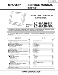
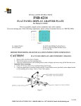
MODEL LC-10A3U-S
A
MODÉLE
How to identify the newly designed sets
ELECTRICAL RATING
DC 12V 24W
(1) The marking A is given on the model label at the bottom of the set.
CONSOMMATION
CC 12V 24W
(2) Serial numbers
SERIAL NO.
210451112
N
DE
SERIE
210451112~
MANUFACTURED
OCTOBER 2002
DATE DE PRODUCTION OCTOBER 2002
OCTOBER2002~
SHARP CORPORATION
(3) The marking "A" is given on the label at the packing case.
MADE IN JAPAN
FABRIQUÉ AU JAPON
CONTENTS
Page
» IMPORTANT SERVICE SAFETY PRECAUTION .................................................................................... 2
» SPECIFICATIONS ................................................................................................................................... 5
» OPERATION MANUAL ............................................................................................................................ 6
» DIMENSIONS .......................................................................................................................................... 7
» REMOVING OF MAJOR PARTS ............................................................................................................. 8
» ADJUSTING PROCEDURE OF EACH SECTION ................................................................................ 11
» TROUBLE SHOOTING TABLE .............................................................................................................. 14
» CHASSIS LAYOUT ................................................................................................................................ 18
» BLOCK DIAGRAM ................................................................................................................................. 20
» OVERALL WIRING DIAGRAM .............................................................................................................. 22
» DESCRIPTION OF SCHEMATIC DIAGRAM ........................................................................................ 24
» SCHEMATIC DIAGRAM ........................................................................................................................ 25
» PRINTED WIRING BOARD ASSEMBLIES ........................................................................................... 32
» PARTS LIST ........................................................................................................................................... 39
» PACKING OF THE SET ......................................................................................................................... 49
SHARP CORPORATION
This document has been published to be used for
after sales service only.
The contents are subject to change without notice.
LC-10A3U
SUPPLEMENT
IMPORTANT SERVICE SAFETY PRECAUTION
Ë
Service work should be perfomed only by qualified service technicians who are thoroughly familiar with all safety checks and the servicing guidelines which follow:
• Use an AC voltmeter having with 5000 ohm per volt, or
higher, sensitivity or measure the AC voltage drop
across the resisor.
• Connect the resistor connection to all exposed metal
parts having a return to the chassis (antenna, metal
cabinet, screw heads, knobs and control shafts,
escutcheon, etc.) and measure the AC voltage drop
across the resistor.
All checks must be repeated with the AC cord plug
connection reversed. (If necessary, a nonpolarized
adaptor plug must be used only for the purpose of
completing these checks.)
Any reading of 0.75V peak (this corresponds to 0.5
milliamp. peak AC.) or more is excessive and indicates
a potential shock hazard which must be corrected
before returning the monitor to the owner.
WARNING
1. For continued safety, no modification of any circuit
should be attempted.
2. Disconnect AC power before servicing.
A
V
C AU T I O N : F O R C O N T I N U E D
PROTECTION AGAINST A RISK OF
FIRE REPLACE ONLY WITH SAME
TYPE F3701 (1.6A, 125V),
F3702(1.6A, 125V) AND F3751
(2.5A, 125V) FUSE.
BEFORE RETURNING THE RECEIVER
(Fire & Shock Hazard)
Before returning the receiver to the user, perform
the following safety checks:
1. Inspect all lead dress to make certain that leads are
not pinched, and check that hardware is not lodged
between the chassis and other metal parts in the
receiver.
2. Inspect all protective devices such as non-metallic
control knobs, insulation materials, cabinet backs,
adjustment and compartment covers or shields,
isolation resistor-capacitor networks, mechanical
insulators, etc.
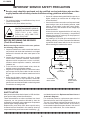
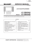
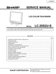
3. To be sure that no shock hazard exists, check for
leakage current in the following manner.
• Plug the AC cord directly into a 110~240 volt AC outlet,
and connect the DC power cable into the receiver's
DC jack. (Do not use an isolation transformer for this
test).
• Using two clip leads, connect a 50k ohm, 10 watt
resistor paralleled by a 0.15µF capacitor in series with
all exposed metal cabinet parts and a known earth
ground, such as electrical conduit or electrical ground
connected to an earth ground.
DVM
AC SCALE
50k ohm
10W
0.15 µF
TEST PROBE
TO EXPOSED
METAL PARTS
CONNECT TO
KNOWN EARTH
GROUND
12345678901234567890123456789012123456789012345678901234567890121234567890123456789012345678901212
12345678901234567890123456789012123456789012345678901234567890121234567890123456789012345678901212
12345678901234567890123456789012123456789012345678901234567890121234567890123456789012345678901212
SAFETY NOTICE
and shaded areas in the Replacement Parts Lists and
Schematic Diagrams.
For continued protection, replacement parts must be
identical to those used in the original circuit.
The use of a substitute replacement parts which do not
have the same safety characteristics as the factory
recommended replacement parts shown in this service
manual, may create shock, fire or other hazards.
Many electrical and mechanical parts in LCD television
have special safety-related characteristics.
These characteristics are often not evident from visual
inspection, nor can protection afforded by them be
necessarily increased by using replacement components
rated for higher voltage, wattage, etc.
Replacement parts which have these special safety
characteristics are identified in this manual; electrical
components having such features are identified by “ å”
12345678901234567890123456789012123456789012345678901234567890121234567890123456789012345678901212
12345678901234567890123456789012123456789012345678901234567890121234567890123456789012345678901212
12345678901234567890123456789012123456789012345678901234567890121234567890123456789012345678901212
2
LC-10A3U
SUPPLEMENT
PRECAUTIONS A PRENDRE LORS DE LA REPARATION
Ë
Ne peut effectuer la réparation qu' un technicien spécialisé qui s'est parfaitement
accoutumé à toute vérification de sécurité et aux conseils suivants.
• Utiliser un voltmètre CA d'une sensibilité d'au moins
5000Ω/V pour mesurer la chute de tension en travers
de la résistance.
• Toucher avec la sonde d'essai les pièces métalliques
exposées qui présentent une voie de retour au châssis
(antenne, coffret métallique, tête des vis, arbres de
commande et des boutons, écusson, etc.) et mesurer
la chute de tension CA en-travers de la résistance.
Toutes les vérifications doivent être refaites après avoir
inversé la fiche du cordon d'alimentation. (Si nécessaire,
une prise d'adpatation non polarisée peut être utilisée
dans le but de terminer ces vérifications.)
Tous les courants mesurés ne doivent pas dépasser
0,5 mA.
Dans le cas contraire, il y a une possibilité de choc
électrique qui doit être supprimée avant de rendre le
récepteur au client.
AVERTISSEMENT
1. N'entreprendre aucune modification de tout circuit.
C'est dangereux.
2. Débrancher le récepteur avant toute réparation.
A
V
P R E C AU T I O N : P O U R L A
PROTECTION CONTINUE CONTRE
LES RISQUES D'INCENDIE,
REMPLACER LE FUSIBLE PAR UN
FUSIBLE DE MEME TYPE F3701
(1.6A, 125V), F3702 (1.6A, 125V),
F3751(2.5A, 125V).
VERIFICATIONS CONTRE L'INCEN-DIE ET
LE CHOC ELECTRIQUE
Avant de rendre le récepteur à l'utilisateur, effectuer
les vérifications suivantes.
1. Inspecter tous les faisceaux de câbles pour s'assurer
que les fils ne soient pas pincés ou qu'un outil ne soit
pas placé entre le châssis et les autres pièces
métalliques du récepteur.
2. Inspecter tous les dispositifs de protection comme les
boutons de commande non-métalliques, les isolants,
le dos du coffret, les couvercles ou blindages de réglage
et de compartiment, les réseaux de résistancecapacité, les isolateurs mécaniques, etc.
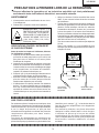
3. S'assurer qu'il n'y ait pas de danger d'électrocution en
vérifiant la fuite de courant, de la facon suivante:
• Brancher le cordon d'alimentation directem-ent à une
prise de courant de 110-240V. (Ne pas utiliser de
transformateur d'isolation pour cet essai).
• A l'aide de deux fils à pinces, brancher une résistance
de 50 kΩ 10 watts en parallèle avec un condensateur
de 0,15µF en série avec toutes les pièces métalliques
exposées du coffret et une terre connue comme une
conduite électrique ou une prise de terre branchée à
la terre.
VTVM
ECHELLE CA
50k ohm
10W
0.15 µF
SONDE D'ESSAI
AUX PIECES
METALLIQUES
EXPOSEES
BRANCHER A UNE
TERRE CONNUE
12345678901234567890123456789012123456789012345678901234567890121234567890123456789012345678901212
12345678901234567890123456789012123456789012345678901234567890121234567890123456789012345678901212
12345678901234567890123456789012123456789012345678901234567890121234567890123456789012345678901212
12345678901234567890123456789012123456789012345678901234567890121234567890123456789012345678901212
AVIS POUR LA SECURITE
identifiées par la marque " å " et hachurées dans la
liste des pièces de remplacement et les diagrammes
schématiques.
Pour assurer la protection, ces pièces doivent être
identiques à celles utilisées dans le circuit d'origine.
L'utilisation de pièces qui n'ont pas les mêmes
caractéristiques que les pièces recommandées par
l'usine, indiquées dans ce manuel, peut provoquer des
électrocutions, incendies, radiations X ou autres
accidents.
De nombreuses pièces, électriques et mécaniques, dans
les téléviseurs présentent des caractéristiques spéciales
relatives à la sécurité, qui ne sont souvent pas évidentes
à vue. Le degré de protection ne peut pas être
nécessairement augmentée en utilisant des pièces de
remplacement étalonnées pour haute tension,
puissance, etc.
Les pièces de remplacement qui présentent ces
caractéristiques sont identifiées dans ce manuel; les
pièces électriques qui présentent ces particularités sont
12345678901234567890123456789012123456789012345678901234567890121234567890123456789012345678901212
12345678901234567890123456789012123456789012345678901234567890121234567890123456789012345678901212
12345678901234567890123456789012123456789012345678901234567890121234567890123456789012345678901212
3
LC-10A3U
SUPPLEMENT
Precautions for using lead-free solder
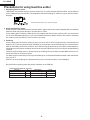
1 Employing lead-free solder
"Main PWB" of this model employs lead-free solder. The LF symbol indicates lead-free solder, and is attached
on the PWBs and service manuals. The alphabetical character following LF shows the type of lead-free solder.
Example:
LFa
Indicates lead-free solder of tin, silver and copper.
2 Using lead-free wire solder
When fixing the PWB soldered with the lead-free solder, apply lead-free wire solder. Repairing with conventional
lead wire solder may cause damage or accident due to cracks.
As the melting point of lead-free solder (Sn-Ag-Cu) is higher than the lead wire solder by 40ºC, we recommend
you to use a dedicated soldering bit, if you are not familiar with how to obtain lead-free wire solder or soldening
bit, contact our service station or service ranch in your area.
3 Soldering
As the melting point of lead-free solder (Sn-Ag-Cu) is about 220°C which is higher than the conventional lead
solder by 40°C, and as it has poor solder wettabillty, you may be apt to keep the soldering bit in contact with the
PWB for extended period of time. However, Since the land may be peeled off or the maximum heat-resistance
temperature of parts may be excoeded, remove the bit from the PWB as soon as you conurm the steady soldering
condition.
Lead-free solder contains more tin, and the end of the soldering bit may be easily corroded. Make sure to tum on
and off the power of the bit as required.
if a different type of solder stays on the tip of the soldering bit, it is alloyed with lead-free solder. Clean the bit after
every use of it.
When the tip of the soldering bit is blackened during use, file it with steel wool or fine sandpaper.
Be careful when replacing parts with polarity indication on the PWB silk.
Lead-free wire solder for servicing
Part No,
★
Description
ZHNDAi123250E
J
φ0.3mm 250g(1roll)
ZHNDAi126500E
J
φ0.6mm 500g(1roll)
ZHNDAi12801KE
J
φ1.0mm
1kg(1roll)
4
Code
BL
BK
BM
LC-10A3U
SUPPLEMENT
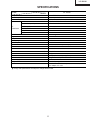
SPECIFICATIONS
ITEMS
LCD panel
Number of pixels
Video color systems
Destination
TV Standard (CCIR)
TV
TV Tuning System
FUNCTION
STEREO
EZ SETUP
CATV
4-LINE COMB FILTER
Brightness
Lamp life
Viewing angles
Audio amplifier
Speakers
Terminals
LC-10A3U
MODEL
10.4” TFT LCD
921,600 pixels VGA
N358, N443, PAL, PAL-M, PAL-N, SECAM, PAL-60
USA/Latin A/Twn
NTSC/PAL-M/PAL-N
PLL 181 ch.
AV STEREO
Yes
125 ch.
Yes
400 cd/m2
60,000 Hours
H: 120° V: 100°
1.0 W × 2
1-3/16 × 1-37/64 in. (3 × 4 cm), 2 pcs
AV-IN 1, S-IN
AV-IN 2
AV-OUT
F-Type
Mini-jack for stereo (3.5 ø) (Rear)
English/French/Spanish
DC 12 V, AC110-240 V
3.97 lbs (1.8 kg) w/o accessories
R/C, Batteries, Wall mount parts, Antenna cable,
AC adapter, AC cord
AV1
AV2
AV OUT
ANT
H/P
OSD LANGUAGE
Power supply
Weight
Accessories
■
Design and specifications are subject to change without notice.
5
LC-10A3U
SUPPLEMENT
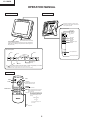
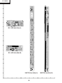
OPERATION MANUAL
Main unit (front view)
Main unit (rear view)
Adjust the set stand to an angle so that
the screen is easily visible. The set stand
can be opened up to 80 .
Rear terminal section
AV input 1
terminal
S
S-Video input
Video input
Audio R/L
V
L
R
AV-IN1
AUDIO
AV-IN2
Audio
Remote sensor window
AV-OUT
Audio
(The actual location is not visible)
Power/standby indicator
V
V
HEADPHONE
A green indicator lights when the power is on and a red indicator
lights when in the standby mode (the indicator will not light when
the power is off).
AV input 2
terminal
AV output
terminal
Headphone output
terminal
Top control panel
ANT
POWER
INPUT
DC input terminal
BRIGHT
VOLUME UP (+)/
DOWN (—)
MUTE
MENU
DISPLAY
Antenna input terminal
+
BRIGHT
DC12V
TV/VIDEO
DISPLAY
VOL
OFF
CH
TV/VIDEO
ON
MAIN POWER
MAIN POWER
CHANNEL UP (▲ )
DOWN (▼ )
MENU
MUTE
■
The
(MUTE), DISPLAY, MENU, VOLUME UP(+)/DOWN(–), CHANNEL UP(▲)/DOWN(▼), and TV/VIDEO
buttons provide the same functions as the buttons on the remote control.
(The MENU button has a slightly different function from the remote control button.)
Remote control
MENU
POWER
MENU
POWER
CH
TV/VIDEO
TV/VIDEO
VOL
-
VOL
+
CH ( ▲ )/( ▼)
▲ Selects next higher channel
▼ Selects next lower channel
CH
FLASHBACK
1
2
3
4
5
6
7
8
9
0
100
DISPLAY
CHANNEL SELECT
MUTE
FLASHBACK
Returns to previous channel
DISPLAY
Press....Displays receiving channel for 10 seconds.
Channel indication reduces in size after
about 10 seconds.
Press again....After the CH call is displayed in large
size, COLOR SYSTEM except N358
and is displayed for 10 seconds, and
then CH will be displayed in small
size only.
↓
Small CH display
↓
LCDTV
No display
↓
The above three displays can
be switched.
MUTE
Press....Stops sound.
6
LC-10A3U
SUPPLEMENT
DIMENSIONS
Unit:inch (mm)
7
LC-10A3U
SUPPLEMENT
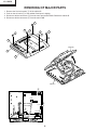
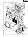
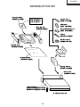
REMOVING OF MAJOR PARTS
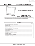
1.
2.
3.
4.
Remove the five lock screws 1 off the cabinet B.
Push on the six hooks 2 of the cabinet B and open it slightly.
Disconnect all the connectors 3 from the tuner and switch PWBs. Detach the cabinet B.
Disconnect all the connectors 4 from the main PWB.
1
1
2
1
2
1
1
2
2
Cabinet B
2
2
P3203
3
P701
P3204
3
3
P2001
SC401
Cabinet A
4
P701
P301
P751
P2001
P2002
4
(Main PWB)
(Main PWB)
SC1203
4
P752 P401
SC1201
4
8
3
LC-10A3U
SUPPLEMENT
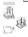
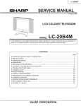
5. Remove the four lock screws 5 off the main PWB.
6. Peel off the tapes 6 and detach the LCD panel unit.
7. Remove the two lock screws 7 off the R/C, LED PWB.
8. Remove the two lock screws 8 off the terminal PWB.
9. Remove the two lock screws 9 off the switch PWB.
10.Remove the two lock screws 0 off the flexible shield.
5
5
Main PWB
LC display unit
6
7
8
Switch PWB
Cabinet A
Tuner PWB
9
7
8
R/C, LED PWB
8
9
10
Cabinet B
Flexible shield
10" LCD Panel unit ass’y
(Rear view)
9
LC-10A3U
SUPPLEMENT
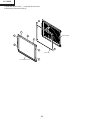
11.Undo the seven hooks q to release the unit frame.
12.Detach the fluorescent lampw.
12
11
11
Panel Holder
11
11
11
11
Lamp unit
10" LCD panel unit
11
10
LC-10A3U
SUPPLEMENT
ADJUSTING PROCEDURE OF EACH SECTION
The best adjustment is made before shipping. If any position deviation is found or after part replace is performed, adjust
as follows.
1. Preparation for Adjustments
(1)Use the exclusive-use AC adapter or stable DC power supply.
AC adapter: UADP-0227CEPZ
DC power supply: 12 ± 0.5V
2. Special mode setting procedure
(1)After initialization of E2PROM the mode is changed to the adjustment mode.
[Procedure]
Connect TP2001 and TP2002 to GND, and turn on the power.
[Description]
» The initialization of microcomputer is as follows.
» AV position, DAC data, G/A data, sound processor data, and video chroma data adjustment values are taken as
defaults.
(2)Adjustment mode
[Procedure]
Short-circuit TP2001 to GND, and turn on the power.
Or short-circuit TP2002 to GND, and turn on the power.
Or holding down the [TV/VIDEO] key and [MENU] key, turn on the main power, and simultaneously press the
(inspection process) [CH "] key and [VOL– ] key to change the mode to the adjustment mode.
[Description]
The manual adjustment or adjustment through communication with the automatic machine is performed.
(3)Inspection mode
[Procedure]
Holding down the [TV/VIDEO] key and [MENU] key, turn on the power.
[Description]
» In the ordinary menu select “VIDEO ADJUST” with the [CH] key, and decide with the [VOL] key. Then select
“PICTURE”, “TINT (only NTSC)”, “COLOR”, “BLACK LEVEL”, “SHARPNESS”, “RED-BLUE”, “GREEN” and
“COLOR SYSTEM” with the [CH] key, and decide with the [VOL] key. After that, adjust values with the [VOL] key.
» VOLUME, PICTURE, TINT (only NTSC), COLOR, BLACK LEVEL, SHARPNESS, RED-BLUE, GREEN change
as follows.
Min.
Center
Max.
(4)Shipping setting mode
[Procedure]
Holding down the [TV/VIDEO] key and [MENU] key, turn on the main power, and simultaneously press the
(inspection process) [CH '] key and [VOL+] key to change the mode to the shipping setting mode.
[Description]
User adjustment and other values are taken as defaults.
If TV is indicated as SETTING COMPLETE, setting has been completed.
3. Cancel of special mode
Turn off the main unit power.
11
LC-10A3U
SUPPLEMENT
4. Reset of lamp error
If the power LED remains red an the power is not turned on, or if repair has been performed, enter the adjustment
mode to reset the lamp error.
For the resetting procedure, refer to "No power" in the "trouble shooting Table" section.
5. Adjustments
Adjustment
Adjusting conditions
Adjusting method
1
B+ Adjustment
(If E2PROM is replaced)
(IC2004)
1. Connect the DC voltmeter to pin (49) 1. Adjust the "B+ Adj" value to
of SC401.
5.0 ± 0.02V with [VOL+] or [VOL-]
key.
* The color of "+B Adj" must be yellow.
2
Inch Size setup
(If E2PROM is replaced)
(IC2004)
1. Go to the adjustment mode.
3
Common-bias
adjustment
1. Receive a B/W channel.
1. Adjust "COM BIAS" to the darkest
screen with [VOL +] and [VOL –] key.
2. Go to the adjustment mode.
3. Select the "COM BIAS" with [MENU] * The color of "COM BIAS" must be
yellow.
key.
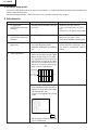
4
TAMP adjustment
1. In the TV mode, the unit receives a
picture of the half color bar signal
whose left top corner is 75% white.
The signal does not have to be the
half color bar as long as the 180th
line from the top and 46th pixel from
the left is 75% white. (Data at this
point is used for adjustment.)
1. Select "MODEL" and adjust to "A2U"
with [VOL +] or [VOL –] key.
* The color of "MODEL" must be yellow.
Upper left 75%
Vertical: 180th line
Horizontal: 46th pixel
480 lines
640 pixels
2. Adjust "NTSC TAMP" on the page 2
of the adjustment process mode so
that the "Y" value on the same page
falls between B0 - BA.
Page 2 of the adjustment process
mode
2
|C O M B I A S
N T S C T A M P
S E C A M T A M P
P A L - M T A M P
P A L - N T A M P
T V H - P E A K I N G
R C U T O F F
G C U T O F F
B C U T O F F
G3
B3
R3
00
G1
B4
Y
DF
00
DE
140
27
27
27
27
3
+3
0
-9
00
B5
Y-Data
(White 75%)
3. Set the values of PAL-M TAMP and
PAL-N TAMP same.
12
LC-10A3U
SUPPLEMENT
Adjustment
Adjusting conditions
5
White balance adjustment 1. Receive the monoscope pattern
signal.
2. Adjust the "RCUTOFF" and
"BCUTOFF" settings on the page 2
of the adjustment process mode to
become the proper white balance.
Do not change the "GCUTOFF"
settings. (It also change the black
level.)
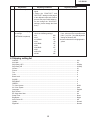
6
Checking and modifying
the settings
(If E2PROM is replaced)
1. Go to the adjustment mode and
check the following settings.
» V0
240
» V16
201
» V16 BIAS
127
» V32
99
» V32 BIAS
127
» V48
47
» V48 BIAS
127
» V63
0
» VGL ADJ
90
» COM
195
Adjusting method
1.See if all the settings are as specified.
If not, select an item in question with
[VOL +] or [VOL –] key and adjust the
setting as shown at left.
* An item selected will be highlighted in
yellow.
6. Shipping setting list
Channel ............................................................................................................................................... 2ch
Air/Cable ............................................................................................................................................. Air
Skip Data_CATV ................................................................................................................................. All Skip
Skip Data_AIR .................................................................................................................................... All Skip
Volume ................................................................................................................................................ 20
Picture ................................................................................................................................................. 30
Tint ...................................................................................................................................................... 0
Color ................................................................................................................................................... 0
Black Level ......................................................................................................................................... 0
SHARP ................................................................................................................................................ 0
RED-BLUE .......................................................................................................................................... 0
GREEN ............................................................................................................................................... 0
TV Color System ................................................................................................................................. N358
AV Color System ................................................................................................................................ Auto
Language ............................................................................................................................................ English
Blue Screen ........................................................................................................................................ Off
EZ Setup Auto Start ............................................................................................................................ On
Sleep Timer ........................................................................................................................................ None
Brightness ........................................................................................................................................... Bright
Auto Power Off ................................................................................................................................... Off
Upside ................................................................................................................................................. Normal
Rigth/Left ............................................................................................................................................ Normal
13
LC-10A3U
SUPPLEMENT
TROUBLE SHOOTING TABLE
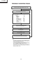
No Power (Power LED indicator still in red)
Go to the adjustment process mode.
1
+B-ADJ
MODEL
INCH SIZE
TIMER
SYSTEM
NTSC PWM FREQ
PAL PWM FREQ
CLOSED CAPTION
V-CHIP
TV GAIN
ERROR NO RESET
160
A2U
10
1
AUTO
OCO
OBD
OFF
OFF
OFF
5
Move the cursor to ERROR NO RESET
and click on it (to reset to zero).
Turn off the power.
Is the power turned on again?
No
Check the back light lamp, D753, Q754, D757 and
their peripheral parts as well as pin (42) of IC2001.
Note:
This model is equipped with the lamp error detection function
that detects the current flowing into the fluorescent lamp and
protects the backlight lamp drive circuit.
If a lamp error is detected, the microprocessor interrupts the
unit and the ERROR NO RESET setting will go up.
When the ERROR NO RESET setting has reached "5", the
microprocessor turns and keeps off the unit's power. To
resume the power, take the above procedure to clear the
ERROR NO RESET setting.
14
No TV and
VIDEO 1
output
No
15
Check LCD
panel voltage
and
waveform.
Yes
Are inputs
and output of No
IC1203 and
IC1204 as
specified?
Yes
Check IC1203,
IC1204 and
their peripheral
parts.
Is input at Pin NO
(73) of IC802
as specified?
Check
IC1201 and
its peripheral
parts.
Are inputs
and outputs
of IC402 as
specified?
Are inputs
and outputs No
of IC1201 as
specified?
Check IC802
and its
peripheral
parts.
Yes
No
Yes
Are inputs
and outputs
of IC802 as
specified?
Check IC802,
AV1 line and
their
peripheral
parts.
Check IC402
and its
peripheral
parts.
Check all the settings on the microprocessor’s adjust process menu.
No picture
at all
No picture
No
Check IC402
and its
peripheral
parts.
Yes
Are Pins (2)
No
and (4) of
IC402 at “H”
and “L”
respectively?
Yes
Is input at Pin No
(1) of IC402
as specified?
Yes
Is output at
Pin (19) of
tuner as
specified?
Yes
Are voltages
No
at Pins (6),
(7) and (9) of
tuner as
specified?
No TV
output
Check the
line in
question.
Yes
Are Pins (65)
and (66) of
IC2001 at “H”
and “L”
respectively?
Check the
line in
question.
Check the
tuner and its
peripheral
parts.
Check the
power line.
Check IC402
and its
peripheral
parts.
Yes
Are Pins (1)
No
and (4) of
IC402 both at
“L”?
YES
Is input at Pin No
(1) of IC402
as specified?
No VIDEO
1 output
Check the
line in
question.
Yes
Are Pins (65)
and (66) of
IC2001 both
at “L”?
Check the
line in
question.
Check J3404,
AV line and
their
peripheral
parts.
No
Is input at Pin
(74) of IC802
as specified?
No VIDEO
2 output
Check
SC3301, SY
line, SC line
and
peripheral
parts.
No
Are inputs at
Pins (71) and
(72) of IC802
as specified?
No S
VIDEO
output
LC-10A3U
SUPPLEMENT
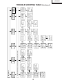
TROUBLE SHOOTING TABLE (Continued)
16
No
No
No VIDEO color
Check J3701, its peripheral
parts and connection cable.
Yes
Is any of T701’s primary side, No
Q701, Q710 and S4701
short-circuited?
Yes
Disconnect F3701 and
F3702. Is the load side
short-circuited?
Check all the settings on the microprocessor’s adjust process menu.
No TV color
No color
Check the secondary-side
load of T701.
Yes
Are the oscillation waveform
at T701’s primary side as
specified?
No
Are secondary outputs
(+38V, +16V, +9V, +5V, -8V)
of T701 as specified?
Yes
Do F3701 and F3702
function?
Check all the settings on the microprocessor’s adjust process menu.
No picture and sound
Is input at Pin (71) of IC802
as specified?
No S-VIDEO color
Check S4701 and
connection cable.
Replace F3701 and F3702.
No
No
No
Check J3301, SC line and
peripheral parts.
Replace the fluorescent lamp
and check the oscillation
waveform again.
Yes
Are the oscillation waveforms No
at the primary side of T751
and T752 as specified?
Yes
Is Pin (34) of IC1201 at “H”?
Yes
Does F3751 function?
Fluorescent lamp failure
Check Q751, Q752, T751,
T752, Q753 and their
peripheral parts.
Yes
Check the line, IC1201 and
its peripheral parts.
Yes
Replace F3751.
LC-10A3U
SUPPLEMENT
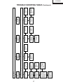
TROUBLE SHOOTING TABLE (Continued)
No sound
from
headphone
17
Check the
speakers and
their peripheral
parts.
Yes
Are inputs at
Pins (5) and (8)
as well as
outputs at Pins
(2) and (11), all
of IC301, as
specified?
Yes
Are inputs and
outputs of
IC303 as
specified?
Yes
Are outputs at
Pins (1) and (7)
of IC903 as
specified?
Yes
Is Pin (53) of
IC2001 at “L”?
No
No
No
No
Check the line
in question,
IC303 and its
peripheral
parts.
Check IC303
and its
peripheral
parts.
Check IC901,
IC903 and their
peripheral
parts.
Muting effect is
on. Check the
FSMU line.
Check the
headphone and
its peripheral
parts.
Yes
Is Pin (55) of
IC2001 at “L”?
No
Check all the settings on the microprocessor’s adjust process menu.
No sound
from
speakers
No sound
Check Q306,
J3404 and their
peripheral
parts.
Check the line
in question.
Yes
Are outputs at
Pins (1) and (7)
of IC902 as
specified?
Yes
Is Pin (52) of
IC2001 at “L”?
No sound
from output
line
No
No
Check IC902
and its
peripheral
parts.
Check the
LMUTE line.
Is input at Pin
(60) of IC901
as specified?
Yes
Is output at Pin
(16) of tuner as
specified?
TV sound
failure
No
No
Check IC901,
Q3301, Q3204,
Q3205 and
their peripheral
parts.
Check the
tuner and its
peripheral
parts.
LC-10A3U
SUPPLEMENT
TROUBLE SHOOTING TABLE (Continued)
LC-10A3U
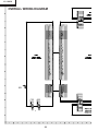
SUPPLEMENT
CHASSIS LAYOUT
MAIN Unit (Side-A)
H
G
F
E
MAIN Unit (Side-A)
D
C
B
FIFOIC
INVERTER
A
1
2
3
4
5
6
18
7
8
9
10
LC-10A3U
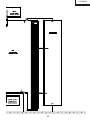
SUPPLEMENT
TUNER Unit
J3404
Q3405
Q3404
J3701
J3302
J3305
J3304
J3403
J3401
J3303
J3301
J3402
F3702
F3701
D3301
F3751
D3401
Q3403
D3402
Q3402 Q3401
Q3303
Q3304
L3202
P3203
Q3301
TUNNER
Q3204
Q3205
C3202
TU3201
P3204
Q3203
P3701
SC3401
Q3201
Q3202
SWITCH Unit (Side-A)
P4004
S4013
S4012
S4017
S4009
S4014
S4015
S4011
S4010
S4016
SWITCH Unit (Side-B)
S4701
R/C, LED Unit
SC4102
RMC
4101
10
11
12
13
14
15
19
16
17
18
19
LC-10A3U
SUPPLEMENT
BLOCK DIAGRAM
H
G
F
E
D
C
B
A
1
2
3
4
5
6
20
7
8
9
10
LC-10A3U
SUPPLEMENT
10
11
12
13
14
15
21
16
17
18
19
LC-10A3U
SUPPLEMENT
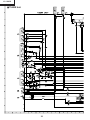
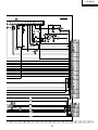
OVERALL WIRING DIAGRAM
H
G
F
E
D
C
B
A
1
2
3
4
5
6
22
7
8
9
10
LC-10A3U
SUPPLEMENT
10
11
12
13
14
15
23
16
17
18
19
LC-10A3U
SUPPLEMENT
DESCRIPTION OF SCHEMATIC DIAGRAM
VOLTAGE MEASUREMENT CONDITION:
CAUTION:
1. Voltages at test points are measured at the
supply voltage of AC 120V. Signals are fed by a
color bar signal generator for servicing purpose and
the above voltages are measured with a 20k ohm/
V tester.
This circuit diagram is original one, therefore there may be a
slight difference from yours.
SAFETY NOTES:
1. DISCONNECT THE AC PLUG FROM THE AC
OUTLET BEFORE REPLACEING PARTS.
2. SEMICONDUCTOR HEAT SINKS SHOULD BE
REGARDED AS POTENTIAL SHOCK HAZARDS
WHEN THE CHASSIS IS OPERATING.
WAVEFORM MEASUREMENT CONDITION:
1. Waveforms at test points are observed at the supply
voltage of AC 120V. Signals are fed by a color bar
signal generator for servicing purpose.
IMPORTANT SAFETY NOTICE:
PARTS MARKED WITH “å” (
) ARE
IMPORTANT FOR MAINTAINING THE SAFETY OF
THE SET. BE SURE TO REPLACE THESE PARTS
WITH SPECIFIED ONES FOR MAINTAINING THE
SAFETY AND PERFORMANCE OF THE SET.
INDICATION OF RESISTOR & CAPACITOR:
RESISTOR
1. The unit of resistance “Ω” is omitted.
(K=kΩ=1000 Ω, M=MΩ).
2. All resistors are ± 5%, unless otherwise noted.
(J= ± 5%, F= ± 1%, D= ± 0.5%)
3. All resistors are 1/10W, unless otherwise noted.
4. All resistors are Carbon type, unless otherwise
noted.
W : Cement
C : Solid
S : Oxide Film
T : Special
N : Metal Coating
CAPACITOR
1. All capacitors are µF, unless otherwise noted.
(P=pF=µµF).
2. All capacitors are 50V, unless otherwise noted.
3. All capacitors are Ceramic type, unless otherwise
noted.
(ML): Mylar
(TA): Tantalum
(PF): Polypro Film
(ST): Styrol
AVIS DE SECURITE IMPORTANT:
LES PIECES MARQUEES “å” (
)SONT
IMPORTANTES POUR MAINTENIR LA SECURITE
DE L'APPAREIL.
NE REMPLACER CES PIEDES QUE PAR DES
PIECES DONT LE NUMERO EST SPECIFIE POUR
MAINTENIR LA SECURITE ET PROTEGER LE BON
FONCTIONNEMENT DE L'APPAREIL.
24
LC-10A3U
SUPPLEMENT
SCHEMATIC DIAGRAM
ËSWITCH and R/C, LED Unit
H
G
F
E
D
C
B
A
1
2
3
4
25
5
6
LC-10A3U
SUPPLEMENT
Ë MAIN Unit-1/2
H
G
F
E
D
C
B
A
1
2
3
4
5
6
26
7
8
9
10
LC-10A3U
SUPPLEMENT
10
11
12
13
14
15
27
16
17
18
19
LC-10A3U
SUPPLEMENT
Ë MAIN Unit-2/2
H
G
F
E
D
C
B
A
1
2
3
4
5
6
28
7
8
9
10
LC-10A3U
SUPPLEMENT
10
11
12
13
14
15
29
16
17
18
19
LC-10A3U
SUPPLEMENT
Ë TUNER Unit
H
G
F
E
D
C
B
A
1
2
3
4
5
6
30
7
8
9
10
LC-10A3U
SUPPLEMENT
10
11
12
13
14
15
31
16
17
18
19
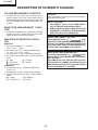
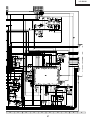
LC-10A3U
SUPPLEMENT
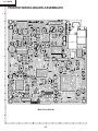
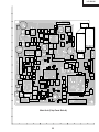
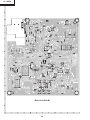
PRINTED WIRING BOARD ASSEMBLIES
H
G
F
E
D
C
B
Main Unit (Side-A)
A
1
2
3
4
32
5
6
1
Q1101
R1127
2
X901
Q1102
P752
P401
B
C1112
R1117
3
33
C1127
C830
C1128
R1116
4
R1235
C2012
R2011
R1222
R2066
R1139
C2011
IC1201
R1202
R1204
5
R1206
R1214
C801
C1216
C752
L706
P2001
C1221
C1218
R1243
D802
R2067
C836
R806
C876
C1210
C1213
C1214
R1150 C1109
C1209
SC1201
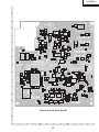
Main Unit (Chip Parts Side-A)
A
6
SC1203
C1206
C821
P755
C753
C755
C754
C721
P754
C759
T752
C768
C766
R771
R750
P753
R769
C713
C769
C767
T751
R749
C736
R732
R707
C712
C740
C737
C739
C306
C310
R738
C746 R737
P301
C314
C1212
C809
L1204
C954
R1209
R1105
IC810
R412
R1211
R418
L804
C848
C708
C719
FB709
R1208
IC2001
C844
C905
R2060
R311
L805
R2019
Q2006
R310
R2046
Q306
R406
R1103
C2021
X2002
R435
R1102
R1111
C901
R1110
C735
C749
R1210
FB1203
R1147
R1107
C741
C318
T701
R1207
C1118
R2041
R2042
R2035
C319
C748
R1205
IC1109
X2003
R2006 R2005
C326
C317
IC301
R1108
R1138
Q709
R1203
R1144
R1137
R1142
C327
C308
C307
C304
C312
G
R1115
C402
C320
C330
C324
C322
C302
C301
Q708
C1107
C938
R1136
C1111
R961
R436
R1114
R960
R1135
R959
R1141 R1140
X2001
R1118 R1129
R1112
R903
R1119
C906
C1117
C958
C405
D1102
R967
C957
R955
R952
R969
L808
C207
C1122
C915
C1101
R965
IC1101
R962
R963
R414
C2003
C944
C902 FB901
C945
R411
C914
L807
C409
R1146
R958
C946
R409
L806
R1145
C924
L809
E
R1143
C
IC901
D
C911
C912
SC401
IC302
TH401
C935
C923
C933
F
C937
C926
LC-10A3U
SUPPLEMENT
H
P701
P751
D710
L701
C733
C703
L705
C328
C751
C321
R434
L752
C403
C404
P2002
R1231
R1244
R1228
D1201
R420
D1203
R964
R1245
C1224
C1223
R1218
C842
R1148 R1149
LC-10A3U
SUPPLEMENT
H
G
F
E
D
C
B
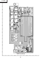
Main Unit (Side-B)
A
1
2
3
4
34
5
6
LC-10A3U
SUPPLEMENT
H
Q307
R307
Q301
C311
R303
C303
R324
C329
R219
Q203
R212
R218
C203
R758
R209
R201
IC201
R203 R204
R745
R1237
R206
R207
C205
C206
Q204
C323
R320
R309
R319
Q308
R725
R726
R325
R326
C325
R208
C763
R330
R753
R754
C757
Q754
Q302
R318
C756
C201
R220
C316
R751
Q752
Q751
R752
Q201
R746
R308
IC704
D751
Q753
C313
R304
R329
C204
D201
R215 R210
C202 R202
R205
Q755
R214 R213 R217
R734
R774
R772
R211
R302
Q304
Q303
C728
R735
Q202
R733
R314 R315
R316 R317
R709
C709
R719
C729
FB703
D704
C722
D703
Q757
R216
C707
C758
R328
D709
C734
IC751
E
C305
D706
D705
FB702
C309
R720
C731
Q703
R706
R739
R740
D707
FB705
FB707
R306
C315
C717
C716
R736
FB706
R305
R712 R721
C710
Q759
R765
R757 R759
R711
FB708
D754
Q756
C760
C701
D711
R770
C764
R768
R766
R767
C738
R713
Q707 D712
D702
FB704
Q758
C765
C761
R722
R703
C706
D755
D753
R718
IC702
C747
F
R708
R705
C705
L2001
R756
D752
C715
Q702
C711
R714
R775
IC701
C704
Q701
R717 R723
Q710
R701
C714
C702
R702
G
R312
R322
C411
R401
R323
C410
R1230
FB1202
R321
IC402
Q305
C406
TP2007
TP2006
C408
Q2005
R405
R407
R968
R966
IC902
R910
R430
C942
R925
R922
R923
C943
C2024
C2002
R2057
R2068
R2061
R2016
R2014
C913
R2056
IC2005
R2055
R2054
C2005
C2022
R2053
R2025
C2007
C916
C2019 C2020
C959 R956
R911
C918
R912
C960 R957
C920
R403
C922
R404
R438
R426
R1132
C1207
D1104
IC1107
IC1106
IC1108
L1202
C1110
C1113
C1115
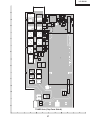
Main Unit (Chip Parts Side-B)
A
1
2
3
4
35
5
6
R904
L902
C925
C928
C412
C401
R429
R421
C1119
R1131
C1120
R1126
D1103
C1121 R1128
C1114
R1134
R1133
C1108
R1124
C1215
R1125
L1205
R917
C930
C931
IC401
R428
C936
C407
R1120
R1130
C1124
R728
R1121
R1122
R1123
C1211
D1101
C1116
IC1110
C964
C963
C927
C929
R902
C921
C1106
C1104
L1203
IC1105
C919
R432
IC1104
R427
IC1202
R1151 R1152
L901
C1105
R901
R1113
IC1103
C1103
C1202
C1123
R1106
R1109
R1101
R1104
FB801
C1102
R826
C962
C917
C961
R810
IC1102
B
C941
C2018
IC2003
R803
R813
C813
C818
C822
R816
C878
R921
IC903
C940
R819
R1236
C939
R920
R919
IC303
C2023
R2058
R909
C955
R918
R2032
R2001
C909
C910
R924
Q2007
C2001
C2004
C956
R419
R908
C2016
R2033
R2002
R2009
C2017
R2045
R2083
C2006
TP2003
C2015
TP2009
R2007
C907
TP2008
R2082
R2028
IC2002
C2010
R2008
R2010
Q2004
R2018
R859
FB802
R1217
R2043 R2049
R2050
R2047
IC808
IC807
R860
R2059
R802
R1224 R1232
C932
R2052
R2031
C806
R1233 C1203
R413
R2051
R2003
TP2002
R858
R811
R814
R1220
C2009
R851
C804
C805
R1221
R1225
Q1201
R801
R804
R1223
R2063
C802
IC802
C831
C825
C875
R1226
C1205
C1204
C874
C1219
TP 802
R410
R2048
TP2001
IC2004
C808 C811
IC1203
R2062
R424
R2044
R2004
TP801
R808 C827
C1220
R1239
R1240
IC1204
Q2003
TP2005
X801
R1242
C
C803
C810
R809 C835
Q1203
Q2001
C814
C815
C820
R827 R861
C819
C817
R831
R828 C839
R2069
R853
R807
R1241
C1201
C2008
C812
C807 C826
L802
R1234
R829 C840
Q1202
L803
R832
D
R830 C841
R834 R833
L801
C816
D2001
C879
R408
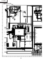
LC-10A3U
SUPPLEMENT
H
G
F
E
D
C
B
A
TUNER Unit (Side-A)
1
2
3
4
36
5
6
J3701
B
1
2
P3701
P3702
C
FH3703
FH3704
FH3701
FH3702
FH3751
FH3752
TU3201
Q3403
Q3401
R3307
R3320
C3403
R3308
C3304
R3411
R3416
L3401
F
R3309
C3313
C3409
R3405
R3303
C3315 R3316
R3417
D3401
J3401
R3315
C3407
C3405
J3305
R3304
C3302
C3201
Q3402
R3410
R3330
J3403
R3409
D3403
J3302
C3314
R3331
Q3404
E
R3313
C3311
Q3405
J3404
J3303
J3304
G
C3301
C3308
R3328
Q3304
3
37
Q3302
R3301 R3302
C3204
4
R3208
R3329
C3210
5
R3202
R3203
R3205
R3201
L3201
R3209
Q3301
C3306
R3322
R3321
R3206
C3208 R3323 C3303
C3209
R3324
Q3203
Q3205
L3202
R3207
Q3204
R3306
SC3401
R3204
R3314
C3205
C3408
D3402
R3401
R3402
C3207
C3402
R3326 R3327
R3319
R3305
J3301
J3402
R3404
R3333
R3332
D
C3312
S3701
LC-10A3U
SUPPLEMENT
H
Q3202
Q3201
C3203
R3334
C3202
R3703
Q3303
C3305
C3309
C3310
R3414
R3310
R3413 R3415
C3404
C3406
R3412
D3301
R3701
A
R3702
TUNER Unit (Chip Parts Side-A)
6
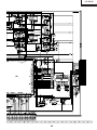
LC-10A3U
SUPPLEMENT
H
G
F
R/C, LED Unit (Side-A)
E
D
R/C, LED Unit (Side-B)
C
B
SWITCH Unit (Side-A)
A
1
2
3
4
38
SWITCH Unit (Side-B)
5
6
LC-10A3U
SUPPLEMENT
Ref. No.
Part No.
★
Description
Code
Ref. No.
★
Part No.
Description
Code
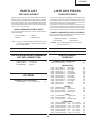
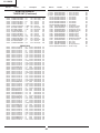
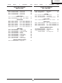
PARTS LIST
LISTE DES PIECES
PARTS REPLACEMENT
CHANGE DES PIECES
Replacement parts which have these special safety characteristics
identified in this manual; electrical components having such features
are identified by å and shaded areas in the Replacement Parts Lists
and Schematic Diagrams. The use of a substitute replacement part
which dose no have the same safety characteristic as the factory
recommended replacement parts shown in this service manual may
create shock, fire or other hazards.
Les pi`eces de rechange qui pr élelesentent ces caract éleristiques
sp éleciales de s élecurit éle, sont identifi élees dans ce manuel : les
pi`eces élelectriques qui pr élesentent ces particularit éles, sont rep
éler élee par la marque å et sont hachur élees dans les listes de
pi`eces et dans les diagrammes sch élematiques.
La substitution d'une pi`ece de rechange par une autre qui ne pr
éLesente pas les m éoemes caract éLeristiques de s élecurit éle que
la pi`ece recommand élee parl'usine et dans ce manuel de service,
peut provoquer une éLelectrocution, un incendie ou toutautre sinistre.
"HOW TO ORDER REPLACEMENT PARTS"
To have your order filled promptly and correctly, please furnish the
following informations.
1. MODEL NUMBER
2. REF. NO.
3. PART NO.
4. DESCRIPTION
in USA:
"COMMENT COMMANDER LES PIECES DE RECHANGE"
Pour que votre commande soit rapidement et correctement remplie,
veuillez fournir les renseignements suivants.
Contact your nearest SHARP Parts Distributor to order.
For location of SHARP Parts Distributor, Please call TollFree; 1-800-BE-SHARP
Part No.
★
Description
2. NO. DE REF
3. NO. DE PIECE
4. DESCRIPTION
in CANADA: Contact SHARP Electronics of Canada Limited
Phone (416) 890-2100
★ MARK: SPARE PARTS-DELIVERY SECTION
Ref. No.
1. NUMERO DU MODELE
★MARQUE: SECTION LIVRAISON DES PIECES DE RECHANGE
Ref. No.
Code
★
Part No.
Description
PRINTED WIRING BOARD ASSEMBLIES
DUNTKA142DE01
(NOT REPLACEMENT ITEM)
TUNER UNIT
DUNTKA142DE01
DUNTKA143DE01
DUNTKA144DE01
DUNTKB686FE01
–
–
–
–
TUNER Unit
SWITCH Unit
R/C, LED Unit
MAIN Unit
NOTE: THE PARTS HERE SHOWN ARE SUPPLIED AS AN
ASSEMBLY BUT NOT INDEPENDENTLY.
TU3201 VTUVT2U5UF553
J Tuner
—
—
—
—
Code
BC
TRANSISTORS
LCD PANEL
NOTE: THE PARTS HERE SHOWN ARE SUPPLIED AS AN
ASSEMBLY BUT NOT INDEPENDENTLY.
RLCDTA019WJZZ J 10" LCD Panel Unit
CV
Q3201
Q3202
Q3203
Q3204
Q3205
Q3301
Q3303
Q3304
Q3401
Q3402
Q3403
Q3404
Q3405
VSDTC144EE/-1Y
VSDTC144EE/-1Y
VSDTC144EE/-1Y
VS2SC2712Y/-1Y
VS2SC3928AR-1Y
VS2SC3928AR-1Y
VSDTC314TK/-1Y
VSDTC314TK/-1Y
VS2SC3928AR-1Y
VS2SC3928AR-1Y
VSDTC144EE/-1Y
VS2SK1467//-1Y
VS2SK1467//-1Y
D3301
D3401
D3402
D3403
VHDDE5SC4M/-1Y
RH-EX1271CEZZY
RH-EX1271CEZZY
RH-EX1271CEZZY
L3201
L3202
L3401
VP-1M220J2R9NY
RCiLC0141CEZZY
VP-1M101J7R7NY
C3201
C3202
C3203
C3204
C3205
C3207
C3208
C3209
VCKYCY1EF104ZY
VCEA4U0JN338M
VCKYCY1HB103KY
VCKYCY1HB102KY
VCCCCY1HH330JY
VCCCCY1HH330JY
VCKYCY1EF104ZY
VCKYCY1HB102KY
J
J
J
J
J
J
J
J
J
J
J
J
J
DTC144EE
DTC144EE
DTC144EE
2SC2712Y
2SC3928AR
2SC3928AR
DTC314TK
DTC314TK
2SC3928AR
2SC3928AR
DTC144EE
2SK1467
2SK1467
AA
AA
AA
AB
AB
AB
AC
AC
AB
AB
AA
AE
AE
DIODES
J
J
J
J
Diode
Zener Diode
Zener Diode
Zener Diode
AF
AB
AB
AB
COILS
J Peaking 22µH
J Coil
J Peaking 100µH
AB
AF
AC
CAPACITORS
39
J
J
J
J
J
J
J
J
0.1
3300
0.01
1000p
33p
33p
0.1
1000p
25V
6.3V
50V
50V
50V
50V
25V
50V
Ceramic
Electrolytic
Ceramic
Ceramic
Ceramic
Ceramic
Ceramic
Ceramic
AA
AE
AA
AA
AA
AA
AA
AA
LC-10A3U
SUPPLEMENT
Ref. No.
★
Part No.
Description
Code
Ref. No.
å
å
å
TUNER UNIT (Continued)
VCEAPF1HW225MY J
VCE9PF1AW106MY J
VCE9PF1AW106MY J
VCKYCY1EF104ZY J
VCKYTV1CB105KY J
VCKYTV1CB105KY J
VCKYCY1HB102KY J
RC-EZ0417CEZZY J
RC-EZ0417CEZZY J
RC-KZ1025CEZZY J
VCKYTV1CB105KY J
VCKYTV1CB105KY J
VCKYCY1EF104ZY J
VCEASH1CN477MY J
VCKYCY1EF104ZY J
VCEAPF0JW336MY J
RC-KZ1025CEZZY J
VCEAPF0JW226MY J
R3201
R3202
R3203
R3204
R3205
R3206
R3207
R3208
R3209
R3301
R3302
R3303
R3304
R3305
R3306
R3307
R3308
R3309
R3310
R3313
R3314
R3315
R3316
R3319
R3320
R3321
R3323
R3324
R3330
R3331
R3332
R3333
R3334
R3401
R3402
R3404
R3405
R3409
R3410
R3411
R3412
R3413
R3414
R3415
R3416
R3417
R3701
R3702
R3703
VRS-CY1JF102JY
VRS-CA1JF561JY
VRS-CY1JF102JY
VRS-CY1JF102JY
VRS-CY1JF153JY
VRS-CY1JF332JY
VRS-CY1JF152JY
VRS-CY1JF331JY
VRS-CY1JF102JY
VRS-CY1JF104JY
VRS-CY1JF101JY
VRS-CY1JF104JY
VRS-CY1JF101JY
VRS-TQ2BD750JY
VRS-CY1JF102JY
VRS-CY1JF104JY
VRS-CY1JF101JY
VRS-CY1JF104JY
VRS-CY1JF102JY
VRS-CY1JF101JY
VRS-CY1JF101JY
VRS-CY1JF101JY
VRS-CY1JF104JY
VRS-TQ2BD750JY
VRS-CY1JF104JY
VRS-CY1JF822JY
VRS-CY1JF101JY
VRS-CY1JF102JY
VRS-TX2HF331JY
VRS-TX2HF331JY
VRS-CR3AD3R9JY
VRS-CR3AD3R9JY
VRS-CY1JF102JY
VRS-TQ2BD750JY
VRS-CY1JF101JY
VRS-CY1JF101JY
VRS-CY1JF000JY
VRS-CY1JF104JY
VRS-TQ2BD750JY
VRS-CY1JF680JY
VRS-CY1JF680JY
VRS-CY1JF223JY
VRS-CY1JF101JY
VRS-CY1JF562JY
VRS-CY1JF272JY
VRS-CY1JF750JY
VRS-TW2ED000JY
VRS-TW2ED000JY
VRS-CY1JF101JY
2.2
10
10
0.1
1
1
1000p
150
150
1
1
1
0.1
470
0.1
33
1
22
50V
10V
10V
25V
16V
16V
50V
16V
16V
10V
16V
16V
25V
16V
25V
6.3V
10V
6.3V
Electrolytic
Elect. (N.P)
Elect. (N.P)
Ceramic
Ceramic
Ceramic
Ceramic
Electrolytic
Electrolytic
Ceramic
Ceramic
Ceramic
Ceramic
Electrolytic
Ceramic
Electrolytic
Ceramic
Electrolytic
AB
AE
AE
AA
AC
AC
AA
AD
AD
AB
AC
AC
AA
AD
AA
AB
AB
AB
1/16W
1/16W
1/16W
1/16W
1/16W
1/16W
1/16W
1/16W
1/16W
1/16W
1/16W
1/16W
1/16W
1/8W
1/16W
1/16W
1/16W
1/16W
1/16W
1/16W
1/16W
1/16W
1/16W
1/8W
1/16W
1/16W
1/16W
1/16W
1/2W
1/2W
1W
1W
1/16W
1/8W
1/16W
1/16W
1/16W
1/16W
1/8W
1/16W
1/16W
1/16W
1/16W
1/16W
1/16W
1/16W
1/4W
1/4W
1/16W
Metal Oxide
Metal Oxide
Metal Oxide
Metal Oxide
Metal Oxide
Metal Oxide
Metal Oxide
Metal Oxide
Metal Oxide
Metal Oxide
Metal Oxide
Metal Oxide
Metal Oxide
Metal Oxide
Metal Oxide
Metal Oxide
Metal Oxide
Metal Oxide
Metal Oxide
Metal Oxide
Metal Oxide
Metal Oxide
Metal Oxide
Metal Oxide
Metal Oxide
Metal Oxide
Metal Oxide
Metal Oxide
Metal Oxide
Metal Oxide
Metal Oxide
Metal Oxide
Metal Oxide
Metal Oxide
Metal Oxide
Metal Oxide
Metal Oxide
Metal Oxide
Metal Oxide
Metal Oxide
Metal Oxide
Metal Oxide
Metal Oxide
Metal Oxide
Metal Oxide
Metal Oxide
Metal Oxide
Metal Oxide
Metal Oxide
AA
AA
AA
AA
AA
AA
AA
AA
AA
AA
AA
AA
AA
AA
AA
AA
AA
AA
AA
AA
AA
AA
AA
AA
AA
AA
AA
AA
AB
AB
AC
AC
AA
AA
AA
AA
AA
AA
AA
AA
AA
AA
AA
AA
AA
AA
AB
AB
AA
RESISTORS
J
J
J
J
J
J
J
J
J
J
J
J
J
J
J
J
J
J
J
J
J
J
J
J
J
J
J
J
J
J
J
J
J
J
J
J
J
J
J
J
J
J
J
J
J
J
J
J
J
1k
560
1k
1k
15k
3.3k
1.5k
330
1k
100k
100
100k
100
75
1k
100k
100
100k
1k
100
100
100
100k
75
100k
8.2k
100
1k
330
330
3.9
3.9
1k
75
100
100
0
100k
75
68
68
22k
100
5.6k
2.7k
75
0
0
100
★
Description
Code
MISCELLANEOUS PARTS
DUNTKA142DE01
C3210
C3301
C3302
C3303
C3304
C3305
C3306
C3311
C3312
C3313
C3314
C3315
C3402
C3403
C3404
C3405
C3406
C3407
Part No.
40
F3701 QFS-B1621GEZZ
F3702 QFS-B1621GEZZ
F3751 QFS-B2521GEZZ
FH3701 QFSHD1002CEZZ
FH3702 QFSHD1002CEZZ
FH3703 QFSHD1002CEZZ
FH3704 QFSHD1002CEZZ
FH3751 QFSHD1002CEZZ
FH3752 QFSHD1002CEZZ
J3301 QSOCD0406GEZZ
J3302 QJAKJ0080CEZZ
J3303 QJAKE0166CEZZ
J3304 QJAKE0167CEZZ
J3305 QJAKJ0080CEZZ
J3401 QJAKJ0080CEZZ
J3402 QJAKE0168CEZZ
J3403 QJAKJ0080CEZZ
J3404 QJAKJ0080CEZZ
J3701 QJAKE0165CEZZ
P3203 QPLGN0280GEZZ
P3204 QPLGN0280GEZZ
P3701 QPLGN1178GEZZ
SC3401 QSOCN0464FJZZY
J
J
J
J
J
J
J
J
J
J
J
J
J
J
J
J
J
J
J
J
J
J
J
Fuse, 1.6A 125V
Fuse, 1.6A 125V
Fuse, 2.5A 125V
Fuse Holder
Fuse Holder
Fuse Holder
Fuse Holder
Fuse Holder
Fuse Holder
S-Video(AV Input1)
Audio(AV Output)
Audio(L)(AV Input1)
Audio(R)(AV Input1)
Audio(AV Input2)
Video(AV Input2)
Video(AV Inpu1)
Video(AV Output)
Headphone Terminal
DC Input Terminal
Plug, 2-pin
Plug, 2-pin
DC Input Terminal
Socket, 50-pin
AD
AD
AD
AA
AA
AA
AA
AA
AA
AF
AF
AE
AE
AF
AF
AE
AF
AF
AE
AB
AB
AC
AH
LC-10A3U
SUPPLEMENT
Ref. No.
★
Part No.
Description
Code
Ref. No.
DUNTKA144DE01
SWITCH UNIT
R/C, LED UNIT
RH-EX1271CEZZY
RH-EX1271CEZZY
RH-EX1283CEZZY
RH-EX1283CEZZY
J
J
J
J
C4001 VCCCCY1HH471JY J 470p
C4002 VCCCCY1HH471JY J 470p
AB
AB
AB
AB
Q4106 VSDTC144EE/-1Y
Q4107 VSUMG4/////-1Y
50V
50V
Ceramic
Ceramic
J
J
J
J
J
J
J
8.2k
12k
27k
56k
8.2k
12k
27k
1/16W
1/16W
1/16W
1/16W
1/16W
1/16W
1/16W
AA
AA
AB
AB
AE
CAPACITORS
Metal Oxide
Metal Oxide
Metal Oxide
Metal Oxide
Metal Oxide
Metal Oxide
Metal Oxide
S4009 QSW-K0088GEZZY J MENU
S4010 QSW-K0088GEZZY J Channel Up(')
S4011 QSW-K0088GEZZY J Channel Down(")
S4012 QSW-K0088GEZZY J MUTE
S4013 QSW-K0088GEZZY J BRIGHT
S4014 QSW-K0088GEZZY J Volume Up(+)
S4015 QSW-K0088GEZZY J Volume Down(-)
S4016 QSW-K0088GEZZY J TV/VIDEO
S4017 QSW-K0088GEZZY J DISPLAY
S4701 QSW-S0213CEZZ J MAIN POWER
AA
AA
AA
AA
AA
AA
AA
16V
Ceramic
AB
Metal Oxide
Metal Oxide
Metal Oxide
Metal Oxide
AA
AA
AA
AA
RESISTORS
R4187
R4188
R4189
R4190
VRS-CY1JF331JY
VRS-CY1JF102JY
VRS-CY1JF472JY
VRS-CY1JF101JY
J
J
J
J
330
1k
4.7k
100
1/16W
1/16W
1/16W
1/16W
MISCELLANEOUS PARTS
SC4102 QPLGN0464TAZZY
RMC4101 RRMCU0239CEZZ
SLD4101 PSLDM4646CEFW
QCNW-5710CEZZ
AD
AD
AD
AD
AD
AD
AD
AD
AD
AE
MISCELLANEOUS PARTS
QPLGN0564TAZZY J Plug, 5-pin
AA
AC
J Zener Diode
J Zener Diode
J Power/standby Indicator
C4120 VCKYTV1CF105ZY J 1
SWITCHES
P4004
J DTC144EE
J UMG4
DIODES
D4120 RH-EX1271CEZZY
D4121 RH-EX1271CEZZY
D4122 RH-PX0368CEZZY
RESISTORS
VRS-CY1JF822JY
VRS-CY1JF123JY
VRS-CY1JF273JY
VRS-CY1JF563JY
VRS-CY1JF822JY
VRS-CY1JF123JY
VRS-CY1JF273JY
Code
TRANSISTORS
Zener Diode
Zener Diode
Zener Diode
Zener Diode
CAPACITORS
R4080
R4081
R4082
R4083
R4084
R4085
R4086
Description
DUNTKA143DE01
DIODES
D4016
D4017
D4018
D4019
★
Part No.
AC
41
J
J
J
J
Plug, 4-pin
Remote Receiver
Shield
Connecting Cord
AC
AG
AD
AC
LC-10A3U
SUPPLEMENT
Ref. No.
★
Part No.
Description
Code
DUNTKB686FE01
MAIN UNIT
INTEGRATED CIRCUITS
IC201
IC301
IC303
IC402
IC701
IC702
IC704
IC802
IC901
IC902
IC903
IC1101
IC1102
IC1103
IC1104
IC1105
IC1106
IC1107
IC1108
IC1109
IC1110
IC1201
IC1202
IC1203
IC1204
IC2001
IC2002
IC2003
IC2004
IC2005
VHiNJM2147M-1Y
VHiLA4227//-1
VHiNJM2283F-1Y
VHiNJM2235M-1Y
VHiAN8005M/-1Y
VHiNJM2377M-1Y
VHiBA033FP/-1Y
VHiVPC3230D1EQ
RH-iX3370CEN1Q
VHiNJM4560M-1Y
VHiNJM4560M-1Y
VHiMB8346BV-1Y
VHiNJM4565V-1Y
VHiNJM4565V-1Y
VHiNJM4565V-1Y
VHiBU4053V/-1Y
VHiNJM4580V-1Y
VHiNJM4580V-1Y
VHiNJM4580V-1Y
VHiNJM353M/-1Y
VHiBU4053V/-1Y
RH-iX3378CEZZQ
VHiPD485505-2Y
VHiSN2G04CT-1Y
VHiSN2G74CT-1Y
RH-iX3448CEZZQ
VHiPST529DM-1Y
VHiTC4W66F/-1Y
VHiBR24C08F-1Y
VHiBA7046F/-1Y
Q201
Q202
Q203
Q204
Q302
Q303
Q304
Q308
Q701
Q702
Q703
Q707
Q708
Q709
Q710
Q751
Q752
Q753
Q754
Q757
Q1101
Q1102
Q1201
Q1202
Q1203
Q2003
Q2004
Q2005
Q2006
VS2SC2712Y/-1Y
VS2SC2712Y/-1Y
VSFMY3/////-1Y
VS2SC2712Y/-1Y
VS2SA1162Y/-1Y
VSDTC314TK/-1Y
VSDTC314TK/-1Y
VSDTC144EE/-1Y
VS2SA1162Y/-1Y
VS2SK2503//-1Y
VS2SC2712Y/-1Y
VSDTC144EE/-1Y
VSFMMT718//-1Y
VSDTC144EE/-1Y
VS2SA1162Y/-1Y
VS2SC5707++-1Y
VS2SC5707++-1Y
VS2SA1162Y/-1Y
VSDTC114YE/-1Y
VSUPA606T//-1Y
VS2SA1729//-1Y
VS2SC4520//-1Y
VSDTC144EE/-1Y
VS2SA1162Y/-1Y
VSDTC144EE/-1Y
VS2SC2712Y/-1Y
VSDTC144EE/-1Y
VSDTA144EE/-1Y
VSDTC144EE/-1Y
D201
D702
D703
D704
D705
D706
D707
VHDDAN222//-1Y
VHDSFPB56//2EY
VHD1SS250//1EY
VHD1SS250//1EY
VHDDAN222//-1Y
VHDSFPB74//2EY
VHDDAN222//-1Y
J
J
J
J
J
J
J
J
J
J
J
J
J
J
J
J
J
J
J
J
J
J
J
J
J
J
J
J
J
J
NJM2147M-TE1
LA4227
NJM2283M
NJM2235M
AN8005M
NJM2377M
BA033FP-E2
VPC3230D-QA-B3
MSP3440G-QA-B8
NJM4560M
NJM4560M
MB88346BPFV
NJM4565V
NJM4565V
NJM4565V
BU4053BCFV-E2
NJM4580V
NJM4580V
NJM4580V
NJM353M
BU4053BCFV-E2
LR38797
UPD485505G-25
SN74AHC2G04HDC
SN74AHC2G74HDC
M306V0ME-119FP
PST529DMT
TC4W66F
BR24C08F-E2
BA7046F
AF
AG
AF
AE
AD
AK
AG
BD
AY
AG
AG
AN
AF
AF
AF
AE
AE
AE
AE
AG
AE
AY
AY
AE
AE
BA
AE
AE
AF
AF
Ref. No.
Part No.
★
D709
D710
D712
D753
D754
D1101
D1102
D1201
D1203
VHDDAN222//-1Y
VHDDAN222//-1Y
VHDDAN222//-1Y
VHDiMN10///-1Y
VHDiMN10///-1Y
VHD1SS250//1EY
VHDDAN222//-1Y
VHDDAN222//-1Y
VHDDAN222//-1Y
J
J
J
J
J
J
J
J
J
2SC2712Y
2SC2712Y
FMY3
2SC2712Y
2SA1162Y
DTC314TK
DTC314TK
DTC144EE
2SA1162Y
2SK2503
2SC2712Y
DTC144EE
FMMT718
DTC144EE
2SA1162Y
2SC5707++
2SC5707++
2SA1162Y
DTC114YE
UPA606T
2SA1729
2SC4520
DTC144EE
2SA1162Y
DTC144EE
2SC2712Y
DTC144EE
DTA144EE
DTC144EE
Diode
Diode
Diode
Diode
Diode
Diode
Diode
Code
AA
AA
AA
AB
AB
AB
AA
AA
AA
PACKAGED CIRCUIT
AH
AG
AD
COILS
L701
L705
L706
L752
L803
L804
L805
L806
L807
L901
L902
L1202
L1203
L1204
L1205
RCiLPA026WJZZ
RCiLC0057CEZZY
RCiLPA026WJZZ
RCiLC0110CEZZY
VP-1M3R3JR93NY
RCiLC0055CEZZY
RCiLC0055CEZZY
VP-1M4R7J1R2NY
VP-1M4R7J1R2NY
VP-1M4R7J1R2NY
VP-1M101J7R7NY
VP-1M470J5R4NY
VP-1M220J2R9NY
VP-1M220J2R9NY
VP-1M220J2R9NY
J
J
J
J
J
J
J
J
J
J
J
J
J
J
J
Coil
Coil
Coil
Coil
Peaking 3.3µH
Coil
Coil
Peaking 4.7µH
Peaking 4.7µH
Peaking 4.7µH
Peaking 100µH
Peaking 47µH
Peaking 22µH
Peaking 22µH
Peaking 22µH
T701
T751
T752
RTRNZ0778CEZZY J Transformer
RTRNZ0764CEZZ J Transformer
RTRNZ0764CEZZ J Transformer
C201
C202
C204
C205
C206
C207
C301
C302
C303
C304
C305
C306
C307
C308
C309
C310
C311
C312
C313
C314
C316
C317
C318
C319
C403
C404
C406
C408
C409
C411
C701
C702
C703
C704
C706
C707
C708
C710
VCKYTV1HF104ZY J
VCKYCY1EF104ZY J
RC-KZ1025CEZZY J
VCKYCY1EF104ZY J
VCKYCY1HF103ZY J
VCEAPF1HW335MY J
VCEAPF1CN106MY J
VCEAPF1CN107MY J
VCKYCY1EF104ZY J
VCEAPF1CN476MY J
VCKYCY1EB223KY J
VCEASH1CN477MY J
VCEAPF1HN225MY J
VCEAPF1HN225MY J
VCKYCY1EB223KY J
VCEAPF1CN476MY J
VCKYCY1EF104ZY J
VCEAPF1CN107MY J
VCKYTV1CF105ZY J
VCEA4U1CN228M J
VCKYCY1EF104ZY J
VCEAPF1HN105MY J
VCEAPF1HN105MY J
VCEAPF0JW226MY J
VCKYTV1AB105KY J
VCKYTV1AB105KY J
VCKYCY1EF104ZY J
VCCCCY1HH331JY J
VCCCCY1HH331JY J
VCCCCY1HH331JY J
VCCCCY1HH471JY J
VCKYTV1CF105ZY J
VCEAPF1CN226MY J
VCKYTV1CF105ZY J
VCKYCY1HB562KY J
VCKYCY1CF334ZY J
VCEAPF0JN226MY J
VCKYTV1CF105ZY J
AD
AD
AD
AF
AB
AD
AD
AB
AB
AB
AC
AC
AB
AB
AB
TRANSFORMERS
å
å
å
AM
AM
AM
CAPACITORS
AB
AB
AB
AB
AB
AC
AC
AA
AB
AE
AB
AA
AE
AA
AB
AE
AE
AB
AB
AD
AF
AE
AA
AB
AA
AB
AA
AA
AA
DIODES
J
J
J
J
J
J
J
Diode
Diode
Diode
Diode
Diode
Diode
Diode
Diode
Diode
X801
RCRSC0012CEZZY J Crystal
X901
RCRSB0250GEZZ J Crystal
X2002 RFiLA0110CEZZ+
J Filter
TRANSISTORS
J
J
J
J
J
J
J
J
J
J
J
J
J
J
J
J
J
J
J
J
J
J
J
J
J
J
J
J
J
Description
AA
AC
AB
AB
AA
AD
AA
42
0.1
0.1
1
0.1
0.01
3.3
10
100
0.1
47
0.022
470
2.2
2.2
0.022
47
0.1
100
1
2200
0.1
1
1
22
1
1
0.1
330p
330p
330p
470p
1
22
1
5600p
0.33
22
1
50V
25V
10V
25V
50V
50V
16V
16V
25V
16V
25V
16V
50V
50V
25V
16V
25V
16V
16V
16V
25V
50V
50V
6.3V
10V
10V
25V
50V
50V
50V
50V
16V
16V
16V
50V
16V
6.3V
16V
Ceramic
Ceramic
Ceramic
Ceramic
Ceramic
Electrolytic
Electrolytic
Electrolytic
Ceramic
Electrolytic
Ceramic
Electrolytic
Electrolytic
Electrolytic
Ceramic
Electrolytic
Ceramic
Electrolytic
Ceramic
Electrolytic
Ceramic
Electrolytic
Electrolytic
Electrolytic
Ceramic
Ceramic
Ceramic
Ceramic
Ceramic
Ceramic
Ceramic
Ceramic
Electrolytic
Ceramic
Ceramic
Ceramic
Electrolytic
Ceramic
AB
AA
AB
AA
AA
AC
AD
AD
AA
AD
AA
AD
AD
AD
AA
AD
AA
AD
AB
AE
AA
AD
AD
AB
AC
AC
AA
AA
AA
AA
AA
AB
AD
AB
AA
AB
AD
AB
LC-10A3U
SUPPLEMENT
Ref. No.
Part No.
★
Description
Code
Ref. No.
AA
AC
AF
AB
AB
AE
AD
AB
AB
AB
AA
AE
AB
AD
AD
AD
AB
AC
AB
AA
AA
AD
AF
AE
AE
AA
AB
AB
AD
AA
AA
AA
AB
AB
AD
AA
AA
AA
AB
AB
AA
AA
AC
AA
AA
AB
AB
AA
AB
AB
AB
AB
AB
AA
AC
AB
AB
AB
AB
AC
AA
AB
AB
AB
AB
AC
AA
AC
AB
AB
AC
AB
C879
C902
C905
C906
C909
C910
C911
C912
C913
C914
C915
C916
C919
C920
C921
C922
C923
C924
C925
C927
C928
C929
C930
C931
C932
C933
C935
C937
C938
C939
C940
C941
C942
C943
C944
C945
C946
C954
C955
C956
C957
C958
C961
C962
C963
C964
C1101
C1102
C1103
C1104
C1105
C1106
C1107
C1108
C1109
C1110
C1111
C1112
C1113
C1114
C1115
C1116
C1117
C1118
C1119
C1120
C1122
C1123
C1124
C1127
C1128
C1201
C1202
C1203
C1204
C1205
DUNTKB686FE01
MAIN UNIT (Continued)
C711
C712
C713
C716
C717
C719
C721
C722
C728
C729
C731
C733
C734
C735
C736
C737
C738
C740
C741
C746
C747
C748
C749
C751
C752
C755
C757
C758
C759
C760
C761
C763
C764
C765
C801
C802
C803
C804
C805
C806
C807
C808
C809
C810
C811
C812
C813
C814
C815
C816
C817
C818
C819
C820
C821
C822
C825
C826
C827
C830
C831
C835
C839
C840
C841
C842
C844
C848
C874
C875
C876
C878
VCKYCY1EB103KY J
VCEAPT1CN226MY J
VCAAPD1CJ396MY J
VCKYTV1CF105ZY J
VCKYTV1CF105ZY J
RC-EZ0420CEZZY J
VCEASK1HN336MY J
VCKYTV1HF104ZY J
VCKYTV1HF104ZY J
VCKYTV1CF105ZY J
VCCCCY1HH181JY J
VCEASH1CN337MY J
VCKYTV1CF105ZY J
RC-EZ0416CEZZY J
RC-EZ0416CEZZY J
RC-EZ1339CEZZY J
RC-KZ1025CEZZY J
VCEAPF1EN475MY J
VCKYTV1CF105ZY J
VCKYCY1EF104ZY J
VCKYCY1HB562KY J
RC-EZ1339CEZZY J
VCAAPD0JJ127MY J
VCEA4U1CN228M J
RC-FZA065WJZZ
J
VCKYCY1HB103KY J
VCKYCY1CB273KY J
VCKYCY1CB273KY J
VCEAPF0JN107MY J
VCKYTV1HB103KY J
VCKYTV1HB103KY J
VCKYCY1HB562KY J
VCKYTV1CF105ZY J
VCKYTV1CF105ZY J
VCEAPF1CN106MY J
VCKYCY1EF104ZY J
VCCCCY1HH7R0DY J
VCCCCY1HH7R0DY J
RC-KZ1025CEZZY J
RC-KZ1025CEZZY J
VCKYCY1HB331KY J
VCKYCY1HB331KY J
VCEASH1CN107MY J
VCKYCY1EF104ZY J
VCKYCY1HB331KY J
RC-KZ1025CEZZY J
RC-KZ1025CEZZY J
VCKYCY1HB102KY J
VCKYTV1CF684ZY J
VCKYTV1CF684ZY J
VCKYTV1CF684ZY J
RC-KZ1025CEZZY J
RC-KZ1025CEZZY J
VCKYCY1EF104ZY J
VCEASH1CN107MY J
RC-KZ1025CEZZY J
RC-KZ1025CEZZY J
VCKYCY1CF224ZY J
VCKYCY1CF224ZY J
VCEAPF0GW107MY J
VCKYCY1EF104ZY J
VCKYCY1CF224ZY J
VCKYCY1CF224ZY J
VCKYCY1CF224ZY J
VCKYCY1CF224ZY J
VCEAPF0GW107MY J
VCKYCY1EF104ZY J
VCEAPF0JW107MY J
RC-KZ1025CEZZY J
RC-KZ1025CEZZY J
VCEAPF0GW107MY J
RC-KZ1025CEZZY J
0.01
22
39
1
1
100
33
0.1
0.1
1
180p
330
1
330
330
220
1
4.7
1
0.1
5600p
220
120
2200
0.22
0.01
0.027
0.027
100
0.01
0.01
5600p
1
1
10
0.1
7p
7p
1
1
330p
330p
100
0.1
330p
1
1
1000p
0.68
0.68
0.68
1
1
0.1
100
1
1
0.22
0.22
100
0.1
0.22
0.22
0.22
0.22
100
0.1
100
1
1
100
1
25V
16V
16V
16V
16V
25V
50V
50V
50V
16V
50V
16V
16V
6.3V
6.3V
16V
10V
25V
16V
25V
50V
16V
6.3V
16V
100V
50V
16V
16V
6.3V
50V
50V
50V
16V
16V
16V
25V
50V
50V
10V
10V
50V
50V
16V
25V
50V
10V
10V
50V
16V
16V
16V
10V
10V
25V
16V
10V
10V
16V
16V
4V
25V
16V
16V
16V
16V
4V
25V
6.3V
10V
10V
4V
10V
Ceramic
Electrolytic
Electrolytic
Ceramic
Ceramic
Electrolytic
Electrolytic
Ceramic
Ceramic
Ceramic
Ceramic
Electrolytic
Ceramic
Electroytic
Electroytic
Electrolytic
Ceramic
Electrolytic
Ceramic
Ceramic
Ceramic
Electrolytic
Electrolytic
Electrolytic
Film
Ceramic
Ceramic
Ceramic
Electrolytic
Ceramic
Ceramic
Ceramic
Ceramic
Ceramic
Electrolytic
Ceramic
Ceramic
Ceramic
Ceramic
Ceramic
Ceramic
Ceramic
Electrolytic
Ceramic
Ceramic
Ceramic
Ceramic
Ceramic
Ceramic
Ceramic
Ceramic
Ceramic
Ceramic
Ceramic
Electrolytic
Ceramic
Ceramic
Ceramic
Ceramic
Electrolytic
Ceramic
Ceramic
Ceramic
Ceramic
Ceramic
Electrolytic
Ceramic
Electrolytic
Ceramic
Ceramic
Electrolytic
Ceramic
43
Part No.
★
VCKYTV1CF684ZY J
VCKYCY1EF104ZY J
VCEAPF1CW106MY J
VCEAPF1CW106MY J
VCKYCY1HB682KY J
VCKYCY1HB682KY J
VCEAPF1CW106MY J
VCEAPF1CW106MY J
VCKYCY1EF104ZY J
RC-EZ0417CEZZY J
VCEAPF0JW336MY J
VCKYCY1EF104ZY J
RC-KZ1025CEZZY J
RC-KZ1025CEZZY J
RC-KZ1025CEZZY J
RC-KZ1025CEZZY J
VCKYCY1EF104ZY J
VCEAPF1CW106MY J
RC-KZ1025CEZZY J
VCCCCY1HH560JY J
VCCCCY1HH560JY J
VCCCCY1HH560JY J
VCCCCY1HH5R0CY J
VCCCCY1HH5R0CY J
VCKYCY1EF104ZY J
RC-EZ0417CEZZY J
VCEAPF1CW226MY J
RC-EZ0417CEZZY J
RC-EZ0417CEZZY J
VCKYCY1HB561KY J
VCKYCY1HB152KY J
VCKYCY1HB152KY J
VCKYCY1HB561KY J
VCKYCY1EF104ZY J
VCEAPF1CW106MY J
VCEAPF1HW225MY J
VCEAPF1HW225MY J
VCEAPF1CW106MY J
VCKYTV1CF105ZY J
VCKYTV1CF105ZY J
VCEAPF1EW475MY J
VCEAPF1EW475MY J
VCKYCY1HB102KY J
VCKYCY1HB102KY J
VCKYCY1HB102KY J
VCKYCY1HB102KY J
VCKYCY1EF104ZY J
VCKYCY1EF104ZY J
VCKYCY1EF104ZY J
VCKYCY1EF104ZY J
VCKYCY1EF104ZY J
VCKYCY1EF104ZY J
VCKYCY1EF104ZY J
VCKYCY1EF104ZY J
VCKYCY1EF104ZY J
VCKYCY1EF104ZY J
VCKYCY1EF104ZY J
VCKYCY1EF104ZY J
VCKYCY1EF104ZY J
VCKYCY1EF104ZY J
VCKYCY1EF104ZY J
VCKYCY1EF104ZY J
VCCCCY1HH560JY J
VCKYCY1EF104ZY J
VCKYTV1CF105ZY J
VCKYTV1EF104ZY J
VCKYTV1CF105ZY J
VCKYCY1EF104ZY J
VCKYCY1EF104ZY J
VCEAPF1CN107MY J
VCE9PF1CN106MY J
VCCCCY1HH220JY J
VCKYCY1EF104ZY J
VCKYCY1EF104ZY J
VCCCCY1HH220JY J
VCCCCY1HH220JY J
Description
0.68
0.1
10
10
6800p
6800p
10
10
0.1
150
33
0.1
1
1
1
1
0.1
10
1
56p
56p
56p
5p
5p
0.1
150
22
150
150
560p
1500p
1500p
560p
0.1
10
2.2
2.2
10
1
1
4.7
4.7
1000p
1000p
1000p
1000p
0.1
0.1
0.1
0.1
0.1
0.1
0.1
0.1
0.1
0.1
0.1
0.1
0.1
0.1
0.1
0.1
56p
0.1
1
0.1
1
0.1
0.1
100
10
22p
0.1
0.1
22p
22p
16V
25V
16V
16V
50V
50V
16V
16V
25V
16V
6.3V
25V
10V
10V
10V
10V
25V
16V
10V
50V
50V
50V
50V
50V
25V
16V
16V
16V
16V
50V
50V
50V
50V
25V
16V
50V
50V
16V
16V
16V
25V
25V
50V
50V
50V
50V
25V
25V
25V
25V
25V
25V
25V
25V
25V
25V
25V
25V
25V
25V
25V
25V
50V
25V
16V
25V
16V
25V
25V
16V
16V
50V
25V
25V
50V
50V
Ceramic
Ceramic
Electrolytic
Electrolytic
Ceramic
Ceramic
Electrolytic
Electrolytic
Ceramic
Electrolytic
Electrolytic
Ceramic
Ceramic
Ceramic
Ceramic
Ceramic
Ceramic
Electrolytic
Ceramic
Ceramic
Ceramic
Ceramic
Ceramic
Ceramic
Ceramic
Electrolytic
Electrolytic
Electrolytic
Electrolytic
Ceramic
Ceramic
Ceramic
Ceramic
Ceramic
Electrolytic
Electrolytic
Electrolytic
Electrolytic
Ceramic
Ceramic
Electrolytic
Electrolytic
Ceramic
Ceramic
Ceramic
Ceramic
Ceramic
Ceramic
Ceramic
Ceramic
Ceramic
Ceramic
Ceramic
Ceramic
Ceramic
Ceramic
Ceramic
Ceramic
Ceramic
Ceramic
Ceramic
Ceramic
Ceramic
Ceramic
Ceramic
Ceramic
Ceramic
Ceramic
Ceramic
Electrolytic
Elect. (N.P)
Ceramic
Ceramic
Ceramic
Ceramic
Ceramic
Code
AB
AA
AB
AB
AA
AA
AB
AB
AA
AD
AB
AA
AB
AB
AB
AB
AA
AB
AB
AB
AB
AB
AA
AA
AA
AD
AB
AD
AD
AA
AA
AA
AA
AA
AB
AB
AB
AB
AB
AB
AB
AB
AA
AA
AA
AA
AA
AA
AA
AA
AA
AA
AA
AA
AA
AA
AA
AA
AA
AA
AA
AA
AB
AA
AB
AB
AB
AA
AA
AD
AD
AA
AA
AA
AA
AA
LC-10A3U
SUPPLEMENT
Ref. No.
★
Part No.
Description
Code
Ref. No.
DUNTKB686FE01
R408
R409
R410
R411
R420
R424
R430
R434
R435
R436
R701
R702
R703
R705
R706
R707
R708
R709
R711
R712
R713
R717
R718
R719
R720
R721
R722
R723
R725
R726
R732
R733
R734
R735
R736
R737
R738
R739
R740
R751
R752
R753
R754
R765
R766
R768
R770
R772
R774
R801
R802
R803
R804
R806
R809
R810
R811
R813
R814
R816
R819
R826
R831
R832
R833
R834
R860
R861
R901
R902
R903
R909
R910
R917
R918
R919
MAIN UNIT (Continued)
C1206
C1207
C1209
C1210
C1211
C1212
C1213
C1214
C1215
C1216
C1218
C1219
C1220
C1221
C1223
C1224
C2001
C2002
C2003
C2006
C2007
C2009
C2010
C2017
C2018
C2019
C2020
C2021
C2022
C2023
C2024
VCEAPF1EW106MY J
VCKYCY1EF104ZY J
VCEAPF0JW107MY J
VCEAPF0GW107MY J
VCKYCY1EF104ZY J
VCKYCY1EF104ZY J
VCEAPF0JW107MY J
VCEAPF0GW107MY J
RC-KZ1025CEZZY J
VCEAPF1EW226MY J
VCEAPF1CN106MY J
VCKYCY1EF104ZY J
VCKYCY1EF104ZY J
VCKYCY1EF104ZY J
VCEAPF1CW106MY J
VCEAPF1EW106MY J
VCKYCY1HB102KY J
VCCCCY1HH221JY J
VCEAPF1HW105MY J
VCKYCY1EF104ZY J
VCKYCY1EF104ZY J
VCKYCY1EF104ZY J
VCKYCY1EF104ZY J
VCKYCY1EF104ZY J
VCCCCY1HH101JY J
VCKYTV1AB105KY J
VCKYCY1HB102KY J
VCEAPF1AW476MY J
VCKYCY1EF104ZY J
VCKYTV1AB105KY J
VCKYCY1HB222KY J
R201
R202
R203
R204
R205
R206
R207
R208
R209
R210
R211
R212
R213
R214
R215
R216
R217
R218
R219
R220
R302
R303
R304
R305
R308
R309
R314
R315
R316
R317
R324
R328
R329
R401
R403
R404
R405
R406
R407
VRS-CY1JF102JY
VRS-CY1JF103FY
VRS-CY1JF102FY
VRS-CY1JF473FY
VRS-CY1JF103JY
VRS-CY1JF103FY
VRS-CY1JF622FY
VRS-CY1JF473FY
VRS-CY1JF123FY
VRS-CY1JF152FY
VRS-CY1JF392FY
VRS-CY1JF332FY
VRS-CY1JF682FY
VRS-CY1JF122FY
VRS-CY1JF102JY
VRS-CY1JF153JY
VRS-CY1JF102JY
VRS-CY1JF391JY
VRS-TV1JD103JY
VRS-CY1JF102JY
VRS-TX2HF8R2JY
VRS-CY1JF561JY
VRS-CY1JF561JY
VRS-TX2HF8R2JY
VRS-CY1JF223JY
VRS-TW2ED222JY
VRS-CY1JF472JY
VRS-CY1JF392JY
VRS-CY1JF472JY
VRS-CY1JF392JY
VRS-CY1JF472JY
VRS-CY1JF104JY
VRS-CY1JF104JY
VRS-CY1JF101JY
VRS-CY1JF101JY
VRS-CY1JF101JY
VRS-CY1JF101JY
VRS-CY1JF101JY
VRS-CY1JF103JY
10
0.1
100
100
0.1
0.1
100
100
1
22
10
0.1
0.1
0.1
10
10
1000p
220p
1
0.1
0.1
0.1
0.1
0.1
100p
1
1000p
47
0.1
1
2200p
25V
25V
6.3V
4V
25V
25V
6.3V
4V
10V
25V
16V
25V
25V
25V
16V
25V
50V
50V
50V
25V
25V
25V
25V
25V
50V
10V
50V
10V
25V
10V
50V
Electrolytic
Ceramic
Electrolytic
Electrolytic
Ceramic
Ceramic
Electrolytic
Electrolytic
Ceramic
Electrolytic
Electrolytic
Ceramic
Ceramic
Ceramic
Electrolytic
Electrolytic
Ceramic
Ceramic
Electrolytic
Ceramic
Ceramic
Ceramic
Ceramic
Ceramic
Ceramic
Ceramic
Ceramic
Electrolytic
Ceramic
Ceramic
Ceramic
AC
AA
AC
AC
AA
AA
AC
AC
AB
AD
AD
AA
AA
AA
AB
AC
AA
AA
AB
AA
AA
AA
AA
AA
AA
AC
AA
AB
AA
AC
AA
Metal Oxide
Metal Oxide
Metal Oxide
Metal Oxide
Metal Oxide
Metal Oxide
Metal Oxide
Metal Oxide
Metal Oxide
Metal Oxide
Metal Oxide
Metal Oxide
Metal Oxide
Metal Oxide
Metal Oxide
Metal Oxide
Metal Oxide
Metal Oxide
Metal Oxide
Metal Oxide
Metal Oxide
Metal Oxide
Metal Oxide
Metal Oxide
Metal Oxide
Metal Oxide
Metal Oxide
Metal Oxide
Metal Oxide
Metal Oxide
Metal Oxide
Metal Oxide
Metal Oxide
Metal Oxide
Metal Oxide
Metal Oxide
Metal Oxide
Metal Oxide
Metal Oxide
AA
AA
AA
AA
AA
AA
AA
AA
AA
AA
AA
AA
AA
AA
AA
AA
AA
AA
AA
AA
AB
AA
AA
AB
AA
AA
AA
AA
AA
AA
AA
AA
AA
AA
AA
AA
AA
AA
AA
RESISTORS
J
J
J
J
J
J
J
J
J
J
J
J
J
J
J
J
J
J
J
J
J
J
J
J
J
J
J
J
J
J
J
J
J
J
J
J
J
J
J
1k
10k
1k
47k
10k
10k
6.2k
47k
12k
1.5k
3.9k
3.3k
6.8k
1.2k
1k
15k
1k
390
10k
1k
8.2
560
560
8.2
22k
2.2k
4.7k
3.9k
4.7k
3.9k
4.7k
100k
100k
100
100
100
100
100
10k
1/16W
1/16W
1/16W
1/16W
1/16W
1/16W
1/16W
1/16W
1/16W
1/16W
1/16W
1/16W
1/16W
1/16W
1/16W
1/16W
1/16W
1/16W
1/16W
1/16W
1/2W
1/16W
1/16W
1/2W
1/16W
1/4W
1/16W
1/16W
1/16W
1/16W
1/16W
1/16W
1/16W
1/16W
1/16W
1/16W
1/16W
1/16W
1/16W
44
Part No.
VRS-CY1JF103JY
VRS-CY1JF101JY
VRS-CY1JF101JY
VRS-CY1JF101JY
VRS-CY1JF101JY
VRS-CY1JF101JY
VRS-CA1JF101JY
VRS-CY1JF105JY
VRS-CY1JF105JY
VRS-CY1JF105JY
VRS-CY1JF1R0JY
VRS-CY1JF154JY
VRS-CY1JF274JY
VRS-TX2HF000JY
VRS-CR3AD821JY
VRS-CY1JF000JY
VRS-CY1JF272FY
VRS-CY1JF123FY
VRS-CY1JF184JY
VRS-CY1JF683FY
VRS-CY1JF133FY
VRS-CY1JF152FY
VRS-CY1JF274JY
VRS-CY1JF563FY
VRS-CY1JF473JY
VRS-CY1JF103JY
VRS-CY1JF105JY
VRS-CY1JF682JY
VRS-CY1JF1R0JY
VRS-CY1JF1R0JY
VRS-TW2ED222JY
VRS-TQ2BD683JY
VRS-CY1JF393JY
VRS-CY1JF223JY
VRS-CY1JF1R0JY
VRS-CY1JF472JY
VRS-TW2ED102JY
VRS-CY1JF102JY
VRS-CY1JF102JY
VRS-TW2ED392JY
VRS-TW2ED392JY
VRS-CY1JF333JY
VRS-CY1JF103JY
VRS-CY1JF103JY
VRS-CA1JF821JY
VRS-CA1JF104JY
VRS-CA1JF562JY
VRS-CY1JF563JY
VRS-CY1JF000JY
VRS-CB1JF221JY
VRS-CB1JF220JY
VRS-CB1JF220JY
VRS-CA1JF101JY
VRS-CY1JF221JY
VRS-CY1JF750JY
VRS-CB1JF220JY
VRS-CY1JF222JY
VRS-CB1JF220JY
VRS-CY1JF332JY
VRS-CA1JF470JY
VRS-CY1JF000JY
VRS-CY1JF101JY
VRS-CY1JF102JY
VRS-CY1JF102JY
VRS-CY1JF102JY
VRS-CY1JF102JY
VRS-CY1JF000JY
VRS-CY1JF000JY
VRS-CY1JF101JY
VRS-CY1JF101JY
VRS-CY1JF101JY
VRS-CY1JF102JY
VRS-CY1JF102JY
VRS-CY1JF105JY
VRS-CY1JF822FY
VRS-CY1JF822FY
★
J
J
J
J
J
J
J
J
J
J
J
J
J
J
J
J
J
J
J
J
J
J
J
J
J
J
J
J
J
J
J
J
J
J
J
J
J
J
J
J
J
J
J
J
J
J
J
J
J
J
J
J
J
J
J
J
J
J
J
J
J
J
J
J
J
J
J
J
J
J
J
J
J
J
J
J
Description
10k
100
100
100
100
100
100
1M
1M
1M
1
150k
270k
0
820
0
2.7k
12k
180k
68k
13k
1.5k
270k
56k
47k
10k
1M
6.8k
1
1
2.2k
68k
39k
22k
1
4.7k
1k
1k
1k
3.9k
3.9k
33k
10k
10k
820
100k
5.6k
56k
0
220
22
22
100
220
75
22
2.2k
22
3.3k
47
0
100
1k
1k
1k
1k
0
0
100
100
100
1k
1k
1M
8.2k
8.2k
1/16W
1/16W
1/16W
1/16W
1/16W
1/16W
1/16W
1/16W
1/16W
1/16W
1/16W
1/16W
1/16W
1/2W
1W
1/16W
1/16W
1/16W
1/16W
1/16W
1/16W
1/16W
1/16W
1/16W
1/16W
1/16W
1/16W
1/16W
1/16W
1/16W
1/4W
1/8W
1/16W
1/16W
1/16W
1/16W
1/4W
1/16W
1/16W
1/4W
1/4W
1/16W
1/16W
1/16W
1/16W
1/16W
1/16W
1/16W
1/16W
1/16W
1/16W
1/16W
1/16W
1/16W
1/16W
1/16W
1/16W
1/16W
1/16W
1/16W
1/16W
1/16W
1/16W
1/16W
1/16W
1/16W
1/16W
1/16W
1/16W
1/16W
1/16W
1/16W
1/16W
1/16W
1/16W
1/16W
Metal Oxide
Metal Oxide
Metal Oxide
Metal Oxide
Metal Oxide
Metal Oxide
Metal Oxide
Metal Oxide
Metal Oxide
Metal Oxide
Metal Oxide
Metal Oxide
Metal Oxide
Metal Oxide
Metal Oxide
Metal Oxide
Metal Oxide
Metal Oxide
Metal Oxide
Metal Oxide
Metal Oxide
Metal Oxide
Metal Oxide
Metal Oxide
Metal Oxide
Metal Oxide
Metal Oxide
Metal Oxide
Metal Oxide
Metal Oxide
Metal Oxide
Metal Oxide
Metal Oxide
Metal Oxide
Metal Oxide
Metal Oxide
Metal Oxide
Metal Oxide
Metal Oxide
Metal Oxide
Metal Oxide
Metal Oxide
Metal Oxide
Metal Oxide
Metal Oxide
Metal Oxide
Metal Oxide
Metal Oxide
Metal Oxide
Metal Oxide
Metal Oxide
Metal Oxide
Metal Oxide
Metal Oxide
Metal Oxide
Metal Oxide
Metal Oxide
Metal Oxide
Metal Oxide
Metal Oxide
Metal Oxide
Metal Oxide
Metal Oxide
Metal Oxide
Metal Oxide
Metal Oxide
Metal Oxide
Metal Oxide
Metal Oxide
Metal Oxide
Metal Oxide
Metal Oxide
Metal Oxide
Metal Oxide
Metal Oxide
Metal Oxide
Code
AA
AA
AA
AA
AA
AA
AA
AA
AA
AA
AA
AA
AA
AB
AC
AA
AA
AA
AA
AA
AA
AA
AA
AA
AA
AA
AA
AA
AA
AA
AA
AA
AA
AA
AA
AA
AA
AA
AA
AA
AA
AA
AA
AA
AA
AA
AA
AA
AA
AC
AC
AC
AA
AA
AA
AC
AA
AC
AA
AB
AA
AA
AA
AA
AA
AA
AA
AA
AA
AA
AA
AA
AA
AA
AA
AA
LC-10A3U
SUPPLEMENT
Ref. No.
Part No.
★
Description
Code
Ref. No.
DUNTKB686FE01
MAIN UNIT (Continued)
R920
R921
R922
R923
R924
R925
R958
R959
R960
R961
R962
R963
R964
R965
R966
R967
R968
R969
R1101
R1102
R1103
R1104
R1105
R1106
R1107
R1108
R1109
R1110
R1111
R1112
R1113
R1114
R1115
R1116
R1117
R1118
R1119
R1120
R1121
R1123
R1124
R1125
R1126
R1127
R1129
R1130
R1132
R1133
R1134
R1135
R1136
R1137
R1138
R1143
R1144
R1145
R1146
R1147
R1149
R1150
R1151
R1152
R1202
R1203
R1204
R1205
R1206
R1207
R1208
R1209
R1210
R1211
VRS-CY1JF822FY
VRS-CY1JF822FY
VRS-CY1JF223JY
VRS-CY1JF223JY
VRS-CY1JF473JY
VRS-CY1JF473JY
VRS-CY1JF104JY
VRS-CY1JF104JY
VRS-CY1JF104JY
VRS-CY1JF104JY
VRS-CY1JF153JY
VRS-CY1JF223JY
VRS-CY1JF473JY
VRS-CY1JF473JY
VRS-CY1JF152JY
VRS-CY1JF152JY
VRS-CY1JF103JY
VRS-CY1JF103JY
VRS-CA1JF333JY
VRS-CA1JF103JY
VRS-CA1JF103JY
VRS-CA1JF333JY
VRS-CY1JF104JY
VRS-CA1JF333JY
VRS-CA1JF103JY
VRS-CA1JF103JY
VRS-CA1JF333JY
VRS-CY1JF104JY
VRS-CY1JF104JY
VRS-CY1JF103FY
VRS-CA1JF333JY
VRS-CY1JF103FY
VRS-CY1JF102JY
VRS-CY1JF102JY
VRS-CY1JF102JY
VRS-CY1JF823FY
VRS-CY1JF472FY
VRS-TW2ED5R6JY
VRS-CY1JF181JY
VRS-CY1JF181JY
VRS-CY1JF472FY
VRS-TW2ED101JY
VRS-CY1JF000JY
VRS-TX2HF000JY
VRS-CY1JF563FY
VRS-TW2ED5R6JY
VRS-CY1JF000JY
VRS-CY1JF223FY
VRS-CY1JF822FY
VRS-CY1JF561JY
VRS-CY1JF000JY
VRS-CY1JF000JY
VRS-CY1JF000JY
VRS-CY1JF103JY
VRS-CY1JF103JY
VRS-CY1JF103JY
VRS-CY1JF103JY
VRS-CY1JF100JY
VRS-CY1JF562JY
VRS-CY1JF000JY
VRS-CY1JF222FY
VRS-CY1JF103FY
VRS-CB1JF220JY
VRS-CA1JF220JY
VRS-CB1JF220JY
VRS-CA1JF220JY
VRS-CB1JF220JY
VRS-CA1JF220JY
VRS-CY1JF560JY
VRS-CA1JF220JY
VRS-CY1JF220JY
VRS-CY1JF221JY
J
J
J
J
J
J
J
J
J
J
J
J
J
J
J
J
J
J
J
J
J
J
J
J
J
J
J
J
J
J
J
J
J
J
J
J
J
J
J
J
J
J
J
J
J
J
J
J
J
J
J
J
J
J
J
J
J
J
J
J
J
J
J
J
J
J
J
J
J
J
J
J
8.2k
8.2k
22k
22k
47k
47k
100k
100k
100k
100k
15k
22k
47k
47k
1.5k
1.5k
10k
10k
33k
10k
10k
33k
100k
33k
10k
10k
33k
100k
100k
10k
33k
10k
1k
1k
1k
82k
4.7k
5.6
180
180
4.7k
100
0
0
56k
5.6
0
22k
8.2k
560
0
0
0
10k
10k
10k
10k
10
5.6k
0
2.2k
10k
22
22
22
22
22
22
56
22
22
220
1/16W
1/16W
1/16W
1/16W
1/16W
1/16W
1/16W
1/16W
1/16W
1/16W
1/16W
1/16W
1/16W
1/16W
1/16W
1/16W
1/16W
1/16W
1/16W
1/16W
1/16W
1/16W
1/16W
1/16W
1/16W
1/16W
1/16W
1/16W
1/16W
1/16W
1/16W
1/16W
1/16W
1/16W
1/16W
1/16W
1/16W
1/4W
1/16W
1/16W
1/16W
1/4W
1/16W
1/2W
1/16W
1/4W
1/16W
1/16W
1/16W
1/16W
1/16W
1/16W
1/16W
1/16W
1/16W
1/16W
1/16W
1/16W
1/16W
1/16W
1/16W
1/16W
1/16W
1/16W
1/16W
1/16W
1/16W
1/16W
1/16W
1/16W
1/16W
1/16W
Metal Oxide
Metal Oxide
Metal Oxide
Metal Oxide
Metal Oxide
Metal Oxide
Metal Oxide
Metal Oxide
Metal Oxide
Metal Oxide
Metal Oxide
Metal Oxide
Metal Oxide
Metal Oxide
Metal Oxide
Metal Oxide
Metal Oxide
Metal Oxide
Metal Oxide
Metal Oxide
Metal Oxide
Metal Oxide
Metal Oxide
Metal Oxide
Metal Oxide
Metal Oxide
Metal Oxide
Metal Oxide
Metal Oxide
Metal Oxide
Metal Oxide
Metal Oxide
Metal Oxide
Metal Oxide
Metal Oxide
Metal Oxide
Metal Oxide
Metal Oxide
Metal Oxide
Metal Oxide
Metal Oxide
Metal Oxide
Metal Oxide
Metal Oxide
Metal Oxide
Metal Oxide
Metal Oxide
Metal Oxide
Metal Oxide
Metal Oxide
Metal Oxide
Metal Oxide
Metal Oxide
Metal Oxide
Metal Oxide
Metal Oxide
Metal Oxide
Metal Oxide
Metal Oxide
Metal Oxide
Metal Oxide
Metal Oxide
Metal Oxide
Metal Oxide
Metal Oxide
Metal Oxide
Metal Oxide
Metal Oxide
Metal Oxide
Metal Oxide
Metal Oxide
Metal Oxide
AA
AA
AA
AA
AA
AA
AA
AA
AA
AA
AA
AA
AA
AA
AA
AA
AA
AA
AA
AA
AA
AA
AA
AA
AA
AA
AA
AA
AA
AA
AA
AA
AA
AA
AA
AA
AA
AA
AA
AA
AA
AA
AA
AB
AA
AA
AA
AA
AA
AA
AA
AA
AA
AA
AA
AA
AA
AA
AA
AA
AA
AA
AC
AA
AC
AA
AC
AA
AA
AA
AA
AA
Part No.
R1214
R1217
R1218
R1220
R1221
R1222
R1223
R1225
R1226
R1228
R1230
R1232
R1233
R1234
R1235
R1236
R1237
R1240
R1241
R1242
R1243
R1244
R1245
R2001
R2002
R2003
R2004
R2007
R2008
R2009
R2010
R2011
R2014
R2016
R2018
R2019
R2025
R2028
R2031
R2035
R2041
R2042
R2045
R2047
R2048
R2049
R2050
R2051
R2052
R2053
R2054
R2055
R2056
R2057
R2058
R2059
R2061
R2062
R2063
R2067
R2068
R2083
VRS-CB1JF101JY
VRS-CY1JF101JY
VRS-CA1JF101JY
VRS-CY1JF472JY
VRS-CB1JF332JY
VRS-CB1JF101JY
VRS-CA1JF101JY
VRS-CY1JF472JY
VRS-CY1JF101JY
VRS-CY1JF000JY
VRS-CY1JF562JY
VRS-CY1JF101JY
VRS-CY1JF101JY
VRS-CY1JF472JY
VRS-CB1JF473JY
VRS-CB1JF473JY
VRS-TW2ED472JY
VRS-CY1JF000JY
VRS-CY1JF103JY
VRS-CY1JF333JY
VRS-CY1JF103JY
VRS-CY1JF562JY
VRS-CY1JF000JY
VRS-CY1JF102JY
VRS-CY1JF102JY
VRS-CY1JF223JY
VRS-CY1JF223JY
VRS-CY1JF223JY
VRS-CY1JF101JY
VRS-CY1JF102JY
VRS-CY1JF101JY
VRS-CB1JF101JY
VRS-CA1JF103JY
VRS-CA1JF223JY
VRS-CA1JF101JY
VRS-CB1JF331JY
VRS-CY1JF103JY
VRS-CB1JF102JY
VRS-CY1JF101JY
VRS-CY1JF102JY
VRS-CA1JF101JY
VRS-CY1JF101JY
VRS-CY1JF223JY
VRS-CY1JF223JY
VRS-CY1JF332JY
VRS-CY1JF332JY
VRS-CY1JF562JY
VRS-CY1JF101JY
VRS-CY1JF101JY
VRS-CY1JF104JY
VRS-CY1JF333JY
VRS-CY1JF103JY
VRS-CY1JF101JY
VRS-CY1JF103JY
VRS-CY1JF474JY
VRS-CY1JF223JY
VRS-CY1JF223JY
VRS-CY1JF333JY
VRS-CY1JF333JY
VRS-CY1JF101JY
VRS-CY1JF101JY
VRS-CY1JF103JY
FB702
FB703
FB704
FB705
FB706
FB708
FB709
FB801
FB802
FB901
FB1202
FB1203
RBLN-0051TAZZY
RBLN-0051TAZZY
RBLN-0051TAZZY
RBLN-0095CEZZY
RBLN-0051TAZZY
RBLN-0095CEZZY
RBLN-0090CEZZY
RBLN-0090CEZZY
RBLN-0090CEZZY
RBLN-0006TAZZY
RBLN-0006TAZZY
RBLN-0076TAZZY
★
J
J
J
J
J
J
J
J
J
J
J
J
J
J
J
J
J
J
J
J
J
J
J
J
J
J
J
J
J
J
J
J
J
J
J
J
J
J
J
J
J
J
J
J
J
J
J
J
J
J
J
J
J
J
J
J
J
J
J
J
J
J
Description
100
100
100
4.7k
3.3k
100
100
4.7k
100
0
5.6k
100
100
4.7k
47k
47k
4.7k
0
10k
33k
10k
5.6k
0
1k
1k
22k
22k
22k
100
1k
100
100
10k
22k
100
330
10k
1k
100
1k
100
100
22k
22k
3.3k
3.3k
5.6k
100
100
100k
33k
10k
100
10k
470k
22k
22k
33k
33k
100
100
10k
1/16W
1/16W
1/16W
1/16W
1/16W
1/16W
1/16W
1/16W
1/16W
1/16W
1/16W
1/16W
1/16W
1/16W
1/16W
1/16W
1/4W
1/16W
1/16W
1/16W
1/16W
1/16W
1/16W
1/16W
1/16W
1/16W
1/16W
1/16W
1/16W
1/16W
1/16W
1/16W
1/16W
1/16W
1/16W
1/16W
1/16W
1/16W
1/16W
1/16W
1/16W
1/16W
1/16W
1/16W
1/16W
1/16W
1/16W
1/16W
1/16W
1/16W
1/16W
1/16W
1/16W
1/16W
1/16W
1/16W
1/16W
1/16W
1/16W
1/16W
1/16W
1/16W
Metal Oxide
Metal Oxide
Metal Oxide
Metal Oxide
Metal Oxide
Metal Oxide
Metal Oxide
Metal Oxide
Metal Oxide
Metal Oxide
Metal Oxide
Metal Oxide
Metal Oxide
Metal Oxide
Metal Oxide
Metal Oxide
Metal Oxide
Metal Oxide
Metal Oxide
Metal Oxide
Metal Oxide
Metal Oxide
Metal Oxide
Metal Oxide
Metal Oxide
Metal Oxide
Metal Oxide
Metal Oxide
Metal Oxide
Metal Oxide
Metal Oxide
Metal Oxide
Metal Oxide
Metal Oxide
Metal Oxide
Metal Oxide
Metal Oxide
Metal Oxide
Metal Oxide
Metal Oxide
Metal Oxide
Metal Oxide
Metal Oxide
Metal Oxide
Metal Oxide
Metal Oxide
Metal Oxide
Metal Oxide
Metal Oxide
Metal Oxide
Metal Oxide
Metal Oxide
Metal Oxide
Metal Oxide
Metal Oxide
Metal Oxide
Metal Oxide
Metal Oxide
Metal Oxide
Metal Oxide
Metal Oxide
Metal Oxide
Code
AA
AA
AA
AA
AC
AA
AA
AA
AA
AA
AA
AA
AA
AA
AC
AC
AA
AA
AA
AA
AA
AA
AA
AA
AA
AA
AA
AA
AA
AA
AA
AA
AA
AA
AA
AC
AA
AA
AA
AA
AA
AA
AA
AA
AA
AA
AA
AA
AA
AA
AA
AA
AA
AA
AA
AA
AA
AA
AA
AA
AA
AA
MISCELLANEOUS PARTS
45
J
J
J
J
J
J
J
J
J
J
J
J
Ferrite Bead
Ferrite Bead
Ferrite Bead
Ferrite Bead
Ferrite Bead
Ferrite Bead
Ferrite Bead
Ferrite Bead
Ferrite Bead
Ferrite Bead
Ferrite Bead
Ferrite Bead
AC
AC
AC
AD
AC
AD
AD
AD
AD
AB
AB
AC
LC-10A3U
SUPPLEMENT
Ref. No.
Part No.
★
Description
Code
Ref. No.
DUNTKB686FE01
J
J
J
J
J
J
J
J
J
Plug, 11-pin
Plug, 3-pin(HV)
Plug, 3-pin(HV)
Plug, 13-pin
Plug, 5-pin
Plug, 4-pin
Socket, 50-pin
Socket, 53-pin
Socket, 30-pin
★
Description
Code
CABINET AND MECHANICAL PARTS
MAIN UNIT (Continued)
P701
QPLGN1178GEZZ
P751
QPLGN0155FJZZY
P752
QPLGN0155FJZZY
P2002 QPLGN1320REZZ
P2003 QPLGN0520REZZ
P2004 QPLGN0420REZZ
SC401 QSOCN0464FJZZY
SC1201 QSOCN0461FJZZY
SC1203 QSOCN0206FJZZY
Part No.
AC
AE
AE
AC
AB
AA
AH
AH
AF
1
1-5
1-6
1-7
1-8
1-9
1-10
1-11
1-12
1-13
1-14
1-15
1-16
1-17
J Front Cabinet Ass’y
(LC-10A3U-S A )
CCABA2425CE03
J Front Cabinet Ass’y
(LC-10A3U-B A )
Not Available
– Front Cabinet
GCOVA1817CESA J LED Cover
GCOVA1850CEKA J R/C Cover
HBDGB3133CESK J Badge, "SHARP"
(LC-10A3U-S A )
HBDGB3133CESH J Badge, "SHARP"
(LC-10A3U-B A )
HDECA0200CESA J Decoration Plate
LANGS0101CEFW J Fixing Metal, x2
LANGS0102CEFW J Fixing Metal, x2
MSPRP0200CEFW J Spring
PSPAG2002CEZZ
J Spacer, x4
PSPAG2003CEZZ
J Spacer, x2
PSPAH0704CEUZ J Spacer, x2
PSPAH1002CEZZ
J Spacer, x2
PSPAH1003CEZZ
J Spacer, x1
PSPAH1004CEZZ
J Spacer, x1
PSPAP0052CEZZ
J Spacer, x1
VSP4030P-558D
J Speaker, x2
XEBSD20P05000
J Screw, x4
2
2-1
2-2
2-3
2-4
2-5
2-6
2-7
2-8
2-9
2-10
2-11
2-12
2-13
2-14
2-15
2-16
2-17
CCABB2291CE03
Not Available
GDAi-1084CESD
HiNDP5629CESA
JBTN-2051CEKA
JKNBP1166CEKA
LANGF9600CEFW
LX-NZ3047GEZZ
PMLT-0316CEZZ
PMLT-0318CEZZ
PMLT-0356CEZZ
PSPAG2004CEZZ
PSPAH1001CEZZ
PZETZ0015CEZZ
QCNW-5760CEZZ
QCNW-6047CEZZ
XBPSF30P10KS0
XEBSD30P08000
J
–
J
J
J
J
J
J
J
J
J
J
J
J
J
J
J
J
3
3-1
3-2
3-3
3-4
3-5
3-6
3-7
3-8
3-9
3-10
Not Available
RLCDTA019WJZZ
KLMP-0116CEZZ
LHLDW1173CEZZ
LHLDZA126WJKZ
PGiDM0100CEZZ
PSHEP0271CEZZ
PSHEP0272CEZZ
PSLDMA125WJFW
PSPAK0035CEZZ
QCNW-6105CEZZ
– 10" LCD Panel Unit Ass’y
10" LCD Panel Unit
J Lamp Unit
J Wire Holder, x1
J Panel Holder
J Light Guide Panel
J Diffusion Sheet, x2
J Reflection Sheet
J Panel Shield
J Spacer
J Connecting Cord
4
4
5
6
7
8
9
10
11
12
13
14
15
16
17
18
HiNDPA282WJSA
HiNDPA283WJSA
HiNDP5803CESA
RCORF0064CEZZ
Not Available
PSLDM4674CEFW
PZETZA005WJZZ
QCNW-5279CEZZ
QCNW-5285CEZZ
QCNW-5538CEZZ
QCNW-5745CEZZ
QCNW-5951CEZZ
QCNW-5710CEZZ
LHLDW1060CEZZ
LHLDW1173CEZZ
PSPAG2000CEZZ
1
1-1
1-2
1-3
1-4
1-4
å
46
CCABA2425CE01
J
J
–
J
J
J
J
J
J
J
J
J
J
Rear Cabinet Ass’y
Rear Cabinet
Set Stand
Indication Label
Operation Button
Power Button
Reinforcement Angle
Antenna Nut, x1
Spacer, x1
Button Spacer, x2
Spacer, x1
Spacer, x1
Spacer, x1
Insulating Sheet
Connecting Cord
Connecting Cord
Screw, x4
Screw, x1
Model Label(LC-10A3U-B A )
Model Label(LC-10A3U-S A )
Caution UL Label
Core
Serial No. Label
Shield, for FFC
Insulating Sheet
Connecting Cord
Connecting Cord
Connecting Cord
Connecting Cord
Connecting Cord
Connecting Cord
Wire Holder, x1
Wire Holder, x1
Spacer, for Button
BD
BD
—
AE
AG
AG
AG
AK
AD
AD
AD
AA
AA
AB
AB
AB
AB
AA
AQ
AA
BG
—
AX
AE
AH
AE
AG
AA
AB
AB
AB
AB
AD
AG
AP
AC
AB
AA
—
CV
AZ
AD
AR
AV
AH
AF
AK
AB
AD
AF
AF
AG
AL
—
AF
AF
AF
AF
AG
AN
AF
AC
AB
AD
AC
LC-10A3U
SUPPLEMENT
CABINET AND MECHANICAL PARTS
5
H
2-4
2-1
2-2
2-8
2-16
2-12
2
7
2-9
2-10
2-11
G
2-13
2-5
2-7
2-3
4
SWITCH Unit
2-17
A
10
F
13
2-15
21
2-6
9
2-14
TUNER Unit
20
20
17
16
3-8
12
18
8
A
3-4
E
3-7
MAIN Unit
20
3-5
3
3-3
3-2
D
3-6
3-1
1-14
1-10
C
1-9
3-10
1-11
1-1
1-7
11
R/C, LED
Unit
1-17
20
6
1-8
1-6
B
3-9
1-16
19
1-2
1-7
14
1-12
1-6
1-4
1-15
1-16
1
A
1-3
1-12
1-13
1
2
3
4
47
1-5
5
6
15
LC-10A3U
SUPPLEMENT
Ref. No.
19
20
21
Part No.
PSPAG2001CEZZ
XEBSD30P08000
XEBSF30P14000
★
Description
J Spacer, R/C, LED Cover
J Screw, x14
J Screw, x5
Code
Ref. No.
AE
AA
AA
Part No.
★
Description
Code
ACCESSORIES
å
å
LANGU9053CE01
QACCD3099CEPZ
QCNW-5730CEZZ
RRMCG1559CESA
TCAUH0011CEZZ
TiNS-7386CEN1
UADP-0227CEPZ
J
J
J
J
J
J
J
Wall Mount Parts
AC Cord
Antenna Cable
Wireless Remote Control
Caution Card
Operation Manual
AC Adapter
AS
AZ
AP
AV
AC
AP
BF
PACKING PARTS
(NOT REPLACEMENT ITEM)
SPAKC5586CEZZ
SPAKC5587CEZZ
SPAKF4002CEZZ
SPAKP1000CEZZ
SPAKX2056CEZZ
SPAKX2060CEZZ
SSAKA0160CEZZ
TLABK0001TAZZ
48
–
–
–
–
–
–
–
–
Packing Case(LC-10A3U-S A )
Packing Case(LC-10A3U-B A )
Packing Material
Wrapping Paper
Buffer Material
Buffer Material
Polyethylene Bag
Carton Label
—
—
—
—
—
—
—
—
LC-10A3U
SUPPLEMENT
PACKING OF THE SET
★ Polyetlylene Bag
(SSAKA0160CEZZ)
Operation Manual
Antenna Cable
(TiNS-7386CEN1)
(QCNW-5730CEZZ)
Batteries (2 pcs.)
AC Adaptor
(UADP-0227CEPZ)
★ Buffer Material
(SPAKX2060CEZZ)
Wireless Remote Control
(RRMCG1559CESA)
AC Cord
(QACCD3099CEZZ)
Wall Mount Parts
(LANGU9053CE01)
★ Buffer Material
(SPAKX2056CEZZ)
★ Wrapping Paper
(SPAKP1000CEZZ)
★ Packing Material
(SPAKF4002CEZZ)
★ Carton Label
(TLABK0001TAZZ)
★ Packing Case
(SPAKC5586CEZZ:LC-10A3U-S
A
)
(SPAKC5587CEZZ:LC-10A3U-B
A
)
★ :Not Replacement Item.
49
LC-10A3U
SUPPLEMENT
COPYRIGHT © 2003 BY SHARP CORPORATION
ALL RIGHTS RESERVED.
No part of this publication may be reproduced,
stored in a retrieval system, or transmitted in
any form or by any means, electronic, mechanical,
photocopying, recording, or otherwise, without
prior written permission of the publisher.
TQ1455-S
Jan. 2003 Printed in Japan
Design and Production Information
Design
: Japan
Production : Japan
MI. KG
SHARP CORPORATION
AV Systems Group
Quality & Reliability Control Center
Yaita, Tochigi 329-2193, Japan