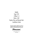
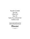
1
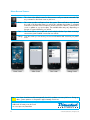
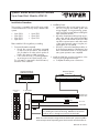
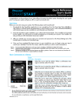
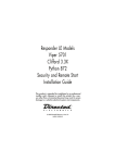
Quick Reference User's Guide
Viper SmartStart VSM100 and VSS4000
Congratulations on the purchase of your state-of-the-art Viper SmartStart system. Reading this user’s guide
prior to using your system will get you off to a quick and smooth start.
Start Here
Before you can start using your system, the following steps must be performed:
1
Download the free SmartStart application to your iPhone or iPod touch from Apple's App Store using
the onscreen instructions.
2
Have the SmartStart system installed by your authorized Viper dealer. Once installed and activated
by the installer, you will receive an email and temporary password prompting you to set up your account through a provided link. Your installer will also provide a printout of this information.
3
Using your iPhone or computer, click on the link and follow the onscreen instructions to set up your
account. You can also set up your account by going to www.viper.com/SmartStart, following the
onscreen instructions and entering the information found on the printout you received from the installer.
4
Once your account has been set up, launch the application. Your system is now ready for use.
Commands at a Glance
Touchscreen
Commands
Lock
Description
Tap this icon to lock the vehicle. When a confirmation message is received, tap it to clear.
Unlock Tap this icon to unlock the vehicle. When a confirmation message is received, tap it to clear.
Touchscreen
Commands
Note:
Menu Bar
Smart
Start
Tap this icon to remote start your vehicle.
When a confirmation message is received, tap
it to clear. The vehicle remote starts and stays
running for the programmed run time (default
is 12 minutes). Tap this icon again to turn off
the engine during the run time.
Trunk
Tap this icon to open trunk. A dialog box will
open, asking you to confirm you want to open
the trunk. Tap "Yes" to confirm, or "No" to cancel the request. If you selected "Yes", tap again
to clear the confirmation message when it pops
up.
Panic
Tap this icon to activate panic mode for 30
seconds. Tap again during this time to turn off.
This feature is used to attract attention if in a
threatened position.
Your vehicle responds exactly the same way as it does when using
the Viper remote control, with audible and visible confirmations.
The amount of time it takes for your vehicle to respond to a command can be affected by cellular
coverage or network congestion.
QRGVSM100 2009-09
Menu Bar and Screens
Menu Bar
Description
Home
This screen is the default screen for direct access to all your remote commands. Tap
any command on the Home screen to perform it.
Alerts
This screen provides notifications from the system. These notifications are indicated
by a red circle above the Alerts icon which also indicates the number of uncleared
notifications received. These notifications can be in the form of alarms, communication
issues or updates to your service plan. The available Alerts may vary depending on
the type of system installed in your vehicle.
Cars
This screen allows you to add and control multiple vehicles if you have a security/
remote start system installed in more than one vehicle.
Settings
From this screen you can access your account information and customize your preferences.
Home Screen
Note:
Alerts Screen
Cars Screen
Settings Screen
Your Viper SmartStart module automatically checks for updates once every 24 hours. During updates, system operation is disrupted for approximately one minute.
Additional information can be found
at: www.viper.com/SmartStart
2
© 2009 Directed Electronics. All rights reserved.
Quick Reference Install Guide
Viper SmartStart Module VSM100
Installation Procedure
This product is compatible with the following models
of Directed Electronics Security and/or Remote Start
systems:
•
•
•
•
Viper
Viper
Viper
Viper
5902
5901
5701
5601
• Viper 5501
• Viper 5301
• Viper 5101
Please read the following before proceeding
1. Customer Information required:
• Record the customer information requested
in step 5a of this procedure. The module ID
# is provided on a sticker which can be affixed to the space provided in step 5a.
• Is this a new account or one being added to
an existing account? Check box(es) in 5a.
This information is required for final verification/
activation of the VSM100.
SmartStart Module
VSM100 (end view)
2. Installation Points:
• Install and test the security/remote start system first using the associated guides and
wiring diagram. If using an existing system,
verify it is fully functional before installing the
Viper SmartStart module.
• Mount the SmartStart module as high as possible in the vehicle (side with Directed label
down). Mount with minimal obstructions that
can affect communications and within reach
of the main Directed system using the provided cables (do not extend).
• DO NOT connect the SmartStart module until the final programming of the Remote Start
main unit and verification of security/remote
start system operations are completed.
3. Install the VSM100 using the information in the
following wiring diagram and steps.
a. Complete the main power connections.
Directed System
(side view)
LED’s
Mating End
View
To SmartStart
Module
1
1
11
2
12
3
13
4
14
13
4
14
5
15
15
6
16
16
7
17
8
18
9
19
10
20
To black 3-pin
Bitwriter Port
P2
Fuse
To Ground
D1
P1
To +12 V
CAUTION: When connecting or disconnecting the P1 connector,
do so holding the connector housing, DO NOT use the harness
bundle to do so as damage may occur to the diode (D1).
NOTE: The connector/port arrangement on the Directed system may differ
to the example shown depending upon which model is installed in the car.
QRNVSM100 2009-09
b. Plug the three wire cable (P2) into the black
3-pin Bitwriter port of the Directed system.
CAUTION: Be careful NOT to plug this P2 connector into the white Door Lock port which also
accepts an identical 3-pin connector. Electrical
damage will occur if plugged into this port.
c. Plug connector P1 into the SmartStart module.
d. When power is connected, the module begins an initialization procedure that may
take several minutes. During this procedure,
progress is reported via the flashing Amber/
Green LED’s next to the P1 connector. When
both LED’s turn on solid, the initialization procedure is completed (See Status LED's for a
description of the various LED states).
4. Re-verify security/remote start system operation:
Perform all basic operations such as Lock, Unlock,
Panic and Remote Start, (Trunk release where applicable) using the supplied remote control. If the
system operates as expected proceed to the next
step (5). If the system does not operate as expected, rectify the problem first.
5. Verify and Activate the VSM100:
The following information and steps need to be
performed for the Verification/Activation of the
VSM100 Viper SmartStart module.
a. Customer Information:
Customer's Full Name:
Customer's Email Address:
Record/place Module ID # here:
New Account:
Existing Account:
If this is an existing account, are you:
adding a new system:
or replacing an existing one:
b.
c.
d.
Log on to:
www.viper.com/SmartStart/activate.
Enter customer information and module ID #
Click onscreen prompt to activate your system.
e. Select whether you are activating the first
SmartStart system for the customer (New Account) or adding a SmartStart system for a
customer with an existing account (Add a
Vehicle).
f. Activate module.
g. Test the SmartStart system from the website
using the supplied function links.
h. Print the customer information which includes
their temporary password. The customer is
also automatically notified via email, which
contains their temporary password and a
link they can click through to finish setting up
their account.
Note: SmartStart response time can vary depending on cellular coverage and network congestion.
Status LED's
Amber LED states:
• Off: No cellular/Wi-Fi communication.
Check connections such as module harness P1 (including D1).
• Flashing slowly: The module is seeking
cellular or Wi-Fi system communication.
If no cell or Wi-Fi coverage is available
the Amber LED will continue to flash slowly, move the vehicle to a location with better reception.
• Flashing quickly: The module is negotiating with a cellular or Wi-Fi system.
• On solid: Communication successfully established.
Green LED states:
• Off: Communication not established with
the remote start main unit.
Check connection at the Bitwriter port,
once connected properly the LED will turn
on.
• Flashing: Active communication in progress between the SmartStart module and
Remote Start main unit.
• On solid: Communication successfully established with the remote start main unit.
Please return this guide and printout from step 5h to
the owner after successfully completing the installation as it contains details required for account setup.
Directed Logo Usage
Logo, Directed with designed in USA.eps
Additional information can be
found at: www.directechs.com
2
© 2009 Directed Electronics. All rights reserved.
Logo, Directed Electronics w-driven.eps