1
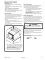
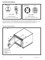
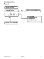
MENUMASTER
Service
COMMERCIAL
MICROWAVE
R
OVEN
This manual is to be used by qualified appliance
technicians only. Maytag does not assume any
responsibility for property damage or personal
injury for improper service procedures done by
an unqualified person.
International
Countertop
Commercial
Microwave
Ovens
RC5PHBU2
RC5PHB2
RC520T2
RC5KFT2
RC5MCTP2
RC5MCTS2
RC5MDTS2
RC5MDTM2
This Base Manual covers general information.
Refer to individual Technical Sheet
for information on specific models.
This manual includes, but is
not limited to the following:
P1331421M
P1331422M
P1331423M
P1331424M
P1331425M
P1331426M
P1331427M
P1331428M
RC520S
RC518SU
RC5MCTP
RC5PHBU
RC5PHB
RC5MCSP
RC5MCSS
RC5MCTS
RC5KFT
RC5MDTS
MRC518SU
MRC520S
RC5MDTM
RC518SU2
RC520S2
RC5MCSP2
RC518U2
MRC520S2
P1327601M
P1327602M
P1327603M
P1327606M
P1327607M
P1327608M
P1327609M
P1327610M
P1327611M
P1327612M
P1327613M
P1327614M
P1327615M
P1331416M
P1331417M
P1331418M
P1331419M
P1331420M
16022149
May 2005
Important Information
Important Notices for Servicers and Consumers
Maytag will not be responsible for personal injury or property damage from improper service procedures. Pride and
workmanship go into every product to provide our customers with quality products. It is possible, however, that during
its lifetime a product may require service. Products should be serviced only by a qualified service technician who is
familiar with the safety procedures required in the repair and who is equipped with the proper tools, parts, testing
instruments and the appropriate service information. IT IS THE TECHNICIANS RESPONSIBILITY TO REVIEW ALL
APPROPRIATE SERVICE INFORMATION BEFORE BEGINNING REPAIRS.
!
WARNING
To avoid risk of severe personal injury or death, disconnect power before working/servicing on appliance to avoid
electrical shock.
To locate an authorized servicer, please consult your telephone book or the dealer from whom you purchased this
product. For further assistance, please contact:
Service Support Center
Contact your local product distributor or vist the Web site at www.amanacommercial.com.
Recognize Safety Symbols, Words, and Labels
! DANGER
DANGER—Immediate hazards which WILL result in severe personal injury or death.
!
WARNING
WARNING—Hazards or unsafe practices which COULD result in severe personal injury or death.
!
CAUTION
CAUTION—Hazards or unsafe practices which COULD result in minor personal injury, product or property
damage.
2
16022149
©2005 Maytag Services
Table of Contents
Important Information .................................................... 2
Important Safety Information ......................................... 4
Wiring ..................................................................... 8
Earthing Instructions ............................................... 8
Servicing of Earthing Products ................................ 8
General Information
Unpacking Oven ..................................................... 9
Oven Placement ..................................................... 9
Radio Interference ................................................... 9
Earthing Instructions ............................................... 9
Microwave Oven Description ................................. 10
Troubleshooting
Power up .............................................................. 11
Standby Condition ................................................ 12
Cook Condition ..................................................... 13
Component Testing Procedures .................................. 14
Power Testing Procedure
Power Test ........................................................... 21
Display Diagnostics
Error Codes .......................................................... 22
Service Test ........................................................... 23-24
Service Information
Proper Handling of Magnetron Tubes .................... 25
Magnetron Failure Modes ..................................... 25
Operating Instructions for the Holaday
HI1501, HI1510, HI1710, and HI1801 .............. 26
Microwave Leakage Test
Equipment ............................................................ 27
Procedure For Measuring Radiation Leakage ....... 27
Measurement With the Outer Panel Removed ...... 27
Measurement With a Fully Assembled Oven ........ 27
Record Keeping and
Notification After Measurement ............................. 27
©2005 Maytag Services
Disassembly
Door Handle ......................................................... 28
Door ..................................................................... 28
Outer Door ............................................................ 28
Inner Door Ring Assembly .................................... 28
Hinge .................................................................... 28
Outer Case ........................................................... 29
Back Panel .......................................................... 29
Splatter Shield ...................................................... 29
Top Touch Panel Assembly ................................... 29
Side Touch Panel Assembly ................................. 29
High Voltage Circuit Board ................................... 29
Interlock Switch Module ....................................... 30
Adjustment .................................................... 30
Display Module ..................................................... 30
Top Rear Magnetron ............................................. 30
Top Front Magnetron ............................................. 30
Bottom Magnetron ................................................ 30
Magnetron Cutout (TCO) ....................................... 31
Cavity Thermal Cutout (TCO) ................................ 31
Triacs ................................................................... 31
Capacitor .............................................................. 31
Transformer .......................................................... 31
Auto Transformer .................................................. 31
Microwave Blower Wheel and Motor ..................... 31
Fan Blade ............................................................. 31
Top Antennas ........................................................ 32
Bottom Antenna .................................................... 32
Antenna Motors .................................................... 32
Oven Tray Removal / Installation ........................... 32
Fuse ..................................................................... 33
Power Cord .......................................................... 33
Light Socket ......................................................... 33
Relay .................................................................... 33
Line Filter ............................................................. 33
Replacing Oven Light Bulb ................................... 33
Component Location ........................................ 34-36
16022149
3
3
Important Safety Information
4
16022149
©2005 Maytag Services
Important Safety Information
©2005 Maytag Services
16022149
5
Important Safety Information
6
16022149
©2005 Maytag Services
Important Safety Information
!
CAUTION
Read the following information to avoid possible
exposure to microwave radiation:
The basic design of the Amana and Menumaster
microwave ovens make it an inherently safe device to
both user and servicer. However, there are some
precautions which should be followed when servicing the
microwave oven to maintain this safety. These are as
follows:
1. Always operate the unit from an adequately earthed
outlet. Do not operate on a two-wire extension cord.
2. Before servicing the unit (if unit is operable), perform
the microwave leakage test.
3. The oven should never be operated if the door does
not fit properly against the seal, the hinges or hinge
bearings are damaged or broken; the choke is
damaged, (pieces missing, etc.); or any other visible
damage can be noted. Check the choke area to
ensure that this area is clean and free of all foreign
matter.
4. If the oven operates with the door open and
produces microwave energy, take the following
steps.
A. Tell the user not to operate the oven.
B. Contact Maytag immediately.
5. Always have the oven disconnected when the outer
case is removed except when making the "live" tests
called for in this Service Manual. Do not reach into
the equipment area while the unit is energized.
Make all connections for the test and check them for
tightness before plugging the cord into the outlet.
6. Always earth the capacitors on the magnetron filter
box and H. V. Capacitor with an insulated-handle
screwdriver before working in the high voltage area of
the equipment compartment. Some types of failures
will leave a charge in these capacitors and the
discharge could cause a reflex action which could
make you injure yourself.
©2005 Maytag Services
7. In the area of the transformer, capacitor, diode, and
magnetron there is HIGH VOLTAGE. When the unit
is operating, keep this area clean and free of anything
which could possibly cause an arc or earthing, etc.
8. Do not for any reason defeat the interlock switches.
There is no valid reason for this action at any time;
nor will it be condoned by Maytag.
9. IMPORTANT: Before returning a microwave to a
customer, check for proper switch interlock action.
The primary and secondary switches MUST actuate
when the door is opened. The monitor switch MUST
close at a 1/64–inch (0.5 mm) when the door is
opened.
10. Before returning a microwave to a customer, verify the
door spacing is reasonably uniform along the top,
bottom, and sides, and that it measures
1
/64–inch (0.5 mm) or less.
11. The Amana or Menumaster microwave oven should
never be operated with:
• Any components removed and/or bypassed.
• Any of the safety interlocks found to be
defective.
• Any of the seal surfaces defective, missing,
or damaged.
12.To ensure that the unit does not emit excessive
microwave leakage and to meet the Department of
Health Human Service guidelines, check the oven
for microwave leakage using leakage monitor as
outlined in the instructions. The maximum leakage
level allowed is 4mW/cm2.
13. If servicer encounters an emission reading over
4 mw/cm2 the servicer is to cease repair and contact
the Maytag Service Department immediately for
further direction. Maytag will contact the proper
Government Agency upon verification of the test
results.
16022149
7
Important Safety Information
!
!
WARNING
Precautions to be observed before and during
servicing to avoid possible exposure to excessive
microwave energy, or electrical shock disconnect
power to oven.
WARNING
To avoid risk of electrical shock, personal injury or
death, make sure these earthing instructions are
followed.
(A) Do not operate or allow oven to be operated with
door open.
Earthing Instructions
(B) Make the following safety checks on all ovens to
be serviced before activating the magnetron or
other microwave source, and make repairs as
necessary:
• Interlock operation
• Proper door closing
• Seal and sealing surfaces (arcing, wear, and
other damage)
• Damage to or loosening of hinges and latches
• Evidence of dropping or abuse
(C) Before turning on microwave power for any service
test or inspection within the microwave generating
compartments, check the magnetron, waveguide or
transmission line, and cavity for proper alignment,
integrity, and connections.
(D) Any failed or misadjusted components in the
interlock, monitor, door seal, microwave
generation, and transmission systems shall be
repaired, replaced or adjusted by procedures
described in this manual before oven is released to
the consumer.
(E) Check microwave leakage to verify compliance with
the federal performance standard should be
performed on each oven prior to release to the
consumer.
!
WARNING
Do not remove earthing prong when installing earthed
appliance in a home or business that does not have
three wire earthing receptacle, under no condition is
earthing prong to be cut off or removed. It is the
personal responsibility of the consumer to contact a
qualified electrician and have properly earthed three
prong wall receptacle installed in accordance with
appropriate electrical codes
Should a two prong adapter plug be required temporarily,
it is the personal responsibility of the consumer to have it
replaced with properly earthed three prong receptacle or
the two prong adapter properly earthed by a qualified
electrician in accordance with appropriate electrical
codes.
Servicing of Earthed Products
The standard accepted color coding for earthing wires is
GREEN or GREEN WITH YELLOW STRIPE. These
earth leads are NOT to be used as current carrying
conductors. It is extremely important that the technician
replace any and all earths prior to completion of the
service call. Under no condition should earth wire be left
off causing a potential hazard to technicians and
consumer.
Wiring
Good service practice is to never route wiring over
terminals and/or sharp edges. This applies to any wiring
without regard to the circuit voltage. Wire insulation
material and thickness is designed and regulated for
electrical spacing purpose only, but cannot always be
relied upon because of possible cuts and/or abrasions,
which can occur during servicing.
8
16022149
©2005 Maytag Services
General Information
Unpacking Oven
• Inspect oven for damage such as dents in door or
inside oven cavity.
• Report any dents or breakage to source of purchase
immediately.
• Do not attempt to use oven if damaged.
• Remove all materials from oven interior.
• If oven has been stored in extremely cold area, wait a
few hours before connecting power.
Radio Interference
Microwave oven operation may cause interference to
radio, television, or similar equipment. Reduce or
eliminate interference by doing the following:
• Clean the door and sealing surfaces of microwave
oven according to instructions in “Care and
Cleaning” section.
• Place radio, television, etc. as far as possible from
the microwave oven.
• Use a properly installed antenna on radio,
television, etc. to obtain stronger signal reception.
Oven Placement
• Do not install oven next to or above source of heat,
such as pizza oven or deep fat fryer. This could cause
microwave oven to operate improperly and could
shorten life of electrical parts.
• Do not block or obstruct oven filter. Allow access for
cleaning.
• Install oven on level countertop surface.
• Place warning label in a conspicuous place close to
microwave oven.
• Outlet should be located so that plug is accessible
when oven is in place.
Earthing Instructions
This appliance MUST be earthed. If an electrical short
circuit occurs, earthing reduces the risk of electric shock
by providing an escape wire for the electric current. The
cord for this appliance has a earthing wire with a
earthing plug. Place the plug into an outlet that is
properly installed and earthed. Do not use a two–prong
adapter.
!
WARNING
To avoid risk of electric shock, personal injury or
death, do not alter the plug and use earthing plug
properly.
Consult a qualified electrician if you do not understand
the earthing instructions or if you wonder whether the
appliance is properly earthed.
A
Keep the electrical power cord dry and do not pinch or
crush it in anyway.
B
The wires in the power cord are colored in accordance
with the following code:
A
• Green/Yellow:
• Blue:
• Brown:
Earth
Neutral
Live
A—Allow at least 7 " (17.8 cm) of clearance around
top and sides of oven. Proper air flow around oven
cools electrical components. With restricted air
flow, oven may not operate properly and life of
electrical parts is reduced.
B—Allow at least 2 9/16 " (6.5 cm) between air
discharge on back of oven and back wall.
©2005 Maytag Services
16022149
9
General Information
Receptacle
Plug
Receptacle
Plug
230 V / 13 AMP
230 V / 16 AMP
Equipment requires a
230 VAC, 50 Hz, 13 amp power supply
Equipment requires a
230 VAC, 50 Hz, 16 amp power supply
Do not use a extension cord. If the product power cord is too short, have a qualified electrician install a
three-prong receptacle. This unit should be plugged into a separate dedicated 230 VAC / 50 Hz power supply. If other
equipment is on the same circuit, an increase in cooking times may be required and fuse can be blown.
Microwave Oven Description
A—Door Handle
B—Spatter Shield
C—Top Control panel
D—Display
E—Side Control Panel
F—Air Filter
10
16022149
©2005 Maytag Services
Troubleshooting
Power Up
Plug oven into power source
with oven door closed.
YES
Error Code Appears.
ITEM
C M
STG QTY
1
2
3
4
Proceed to DISPLAY DIAGNOSTICS.
POWER
NO
LMT
PREHEAT NOT
READY
STANDBY
COOK
LEVEL
1.
2.
3.
4.
5.
6.
YES
POWER UP CONDITION NORMAL
©2005 Maytag Services
16022149
No line voltage.
Inoperative power cord.
Inoperative fuse.
Inoperative display board.
Inoperative H.V. board.
Broken or loose wire connection.
11
Troubleshooting
Standby Condition
Open oven door.
ITEM
C M
STG QTY
1
2
3
4
LMT
POWER
PREHEAT NOT
READY
STANDBY
NO
COOK
LEVEL
1. Inoperative interlock switch assembly (primary).
2. Inoperative H.V. board.
3. Broken or improper wire connections.
Yes
Oven light is on?
NO
1.
2.
3.
4.
5.
Inoperative light bulb.
Inoperative light socket.
Inoperative auto-transformer.
Inoperative H.V. board.
Broken or improper wire connections.
1.
2.
3.
4.
Inoperative blower motor.
Inoperative auto-transformer.
Inoperative H.V. board.
Broken or improper wire connections.
1.
2.
3.
4.
5.
Inoperative antenna motor.
Binding gears.
Inoperative auto-transformer.
Inoperative H.V. board.
Broken or improper wire connections.
Yes
Blower motor operates?
NO
Yes
Antenna motor(s) operate?
Yes
NO
"Standby Condition" normal - proceed to
"Cook Condition".
12
16022149
©2005 Maytag Services
Troubleshooting
Cook Condition
Place cup of water in
oven and close oven door.
Flashing
ITEM
C M
NO
STG QTY
1
2
3
4
LMT
POWER
PREHEAT NOT
READY
COOK
LEVEL
STANDBY
1. Beep not programmed into oven.
2. Pad not programmed.
Display indicates 00:00 and beeps rapidly.
3. Inoperative touch panel.
4. Inoperative H.V. board.
5. Broken or improper wire connections.
Push pad number 1.
Pad beeps when pushed?
Yes
ITEM
C M
STG QTY
1
2
3
4
LMT
POWER
PREHEAT NOT
READY
STANDBY
NO
COOK
LEVEL
1. Magnetron TCO opened in mid-cycle:
"HOT" displays and blower operates.
When TCO resets, blower shuts OFF
and display goes blank.
If TCO does not reset within 2 minutes,
The H.V. board will turn off blower
and the display goes blank.
Display starts counting down.
Yes
Heats very slowly.
NOTE: Verify by performing power test (page 19).
1. One inoperative diode.
2. One inoperative capacitor.
3. One inoperative magnetron.
4. Broken or improper wire connection.
Display counting down to "0" and
beep sounds.
Yes
Open oven door, water is properly heated?
Yes
Oven is operating properly.
NO
No heat.
1. Inoperative triac.
2. Inoperative diodes.
3. Inoperative capacitors.
4. Inoperative high voltage transformer.
5. Inoperative H.V. board.
6. Inoperative or misadjusted interlock
switch assembly (secondary).
7. Broken or improper wire connections.
NOTE: Shut down after cook cycle - door closed - factory preset at 60 seconds, but can be changed with user options.
Shut down, door open - approximately 2 minutes. Blower shuts down and display indicates door.
©2005 Maytag Services
16022149
13
Component Testing Procedures
!
WARNING
To avoid risk of electrical shock, personal injury or death; disconnect power to oven and discharge capacitor
before servicing, unless testing requires power.
Refer to Technical Sheets for specific model information.
Illustration
Component
Thermal cutout
Test
Disconnect all wires from TCO.
Measure resistance across terminals.
Magnetron TCO ..................................
Magnetron TCO ..................................
Magnetron TCO ..................................
Relay TCO ..........................................
Cavity TCO .........................................
Cavity TCO .........................................
Cavity TCO .........................................
Diode
Discharge Capacitor
Remove diode lead from capacitor and
connect ohmmeter.
Triac
Results
Open at 149°C (300°F) and
closes at 125°C (257°F)
Open at 280°F (138°C) and
closed at 180°F (82°C)
Open at 300°F (149°C) and
closed at 257°F (125°C)
Open at 235°F (113°C) and closed at
150°F (66°C)
Opens at 128°C (262°F)
Opens at 219°F (104°C)
Opens at 262°F (128°C)
Infinite resistance should be measured
in one direction and 50KΩ or more in
the opposite direction.
Reverse leads for second test.
NOTE: Ohmmeter must contain a
battery of 6 volts minimum.
Resistance Check
Disconnect wires to triac.
Caution - Do not operate oven with
wire to terminal MT2 removed.
MT2
MT1
GA TE
Triac 1 (center)
Triac 2 (left)
Triac 3 (right
Capacitor
Some units may use
more then one type of
capacitor. Refer to
Parts Manual for
correct capacitor
quantity.
Snubber assembly
Magnetron
Blower motor
Measure resistance from:
MT1 to MT2 .........................................
MT1 to Gate.........................................
MT2 to Gate.........................................
All terminals to ground .........................
Voltage Check
Measure voltage from:
MT1 to Gate
Discharge Capacitor
Remove wires from capacitor terminals
and connect ohmmeter, set on highest
resistance scale to terminals.
Between Terminals: Meter should
momentarily deflect towards zero then
return to over 5 MΩ. If no deflection
occurs, or if continuous deflection
occurs, replace capacitor.
Also check between each terminal and
capacitor case.
Disconnect wires to snubber.
Terminal to Case: Infinite resistance
Measure resistance across terminals ........
Infinite
Discharge Capacitor
Between Terminals: Less than 1 Ω
Remove wires from magnetron and
connect ohmmeter to terminals. Also
check between each terminal and ground.
Each terminal to ground measures
Infinite resistance.
Note: This test is not conclusive. If
oven does not heat and all other
components test good replace the
magnetron and retest.
Remove all wires from motor.
Measure resistance across coil .................
14
Infinite
Approximately 60 Ω
Infinite
Infinite
0.8 VAC when energized. If no
voltage, check H.V. board and wiring.
16022149
Approximately 25 Ω
©2005 Maytag Services
Component Testing Procedures
!
WARNING
To avoid risk of electrical shock, personal injury or death; disconnect power to oven and discharge capacitor
before servicing, unless testing requires power.
Refer to Technical Sheets for specific model information.
Illustration
6
COM
Component
Transformer
Test
Discharge Capacitor
Remove all wires from terminals.
5
4
5
230 V
Measure resistance from:
230 to COM.............................................
230 to Ground .........................................
Terminal 5 to 6 ........................................
Terminal 4 to Ground ..............................
6
COM
230 VAC
Results
Less than 1 Ω
Infinite
Less than 1 Ω
Approximately 65 Ω
4
Transformer
COM
Discharge Capacitor
Remove all wires from terminals.
5
6
4
5
6
230
TCO
220
COM
220 VAC
230 VAC
4
Interlock switch
Door Closed
2
3 Secondary
7
4
8
7
5 Primary
8 Monitor
2
4
3
5
Lamp receptacle
(some models)
Antenna motor
Relay
0
1
This relay contains a
diode in the coil
circuit.
2 4 6 8
Measure resistance from:
230 to COM.............................................
208 to COM.............................................
230 to Ground .........................................
208 to Ground .........................................
Terminal 5 to 6 ........................................
Terminal 4 to Ground ..............................
Disconnect wires to switch.
With door open measure resistance from:
Terminal 2 to 3 ........................................
Terminal 4 to 5 ........................................
Terminal 7 to 8 ........................................
With door closed measure resistance from:
Terminal 2 to 3 ........................................
Terminal 4 to 5 ........................................
Terminal 7 to 8 ........................................
Test continuity of receptacle terminals.
Black
White
Brown
Infinite
Infinite
Indicates continuity
Indicates continuity
Indicates continuity
Infinite
Indicates continuity if bulb is good
and screwed in.
Remove all wires from terminals.
Measure resistance from:
Terminal to terminal ....................................
Approximately 12K Ω
Measure resistance from:
Terminal 0 to terminal 1 (coil) ..................
Approximately 6 to 7 MΩ
0
2
Line filter
Less than 1 Ω
Less than 1 Ω
Infinite
Infinite
Less than 1 Ω
Approximately 70 Ω
1
4
6
8
NOTE: Analog meter is
recommended for measurement.
NOTE: If using a digital meter it must
contain a battery of 6 volts minimum.
Disconnect wire from terminals.
Measure resistance of the following
terminals:
Blue
Refer to Parts Manual
for proper power cord
part number.
©2005 Maytag Services
Terminal block
White to Blue..........................................
Black to Brown .......................................
Visual check.
<1Ω
<1Ω
Verify fuse holding terminals are not
damaged.
Verify terminals are not damaged.
Power cord
Measure resistance of wires.
Continuity should be indicated on
each wire.
Verify polarity and grounding.
16022149
15
Component Testing Procedures
!
WARNING
To avoid risk of electrical shock, personal injury or death; disconnect power to oven and discharge capacitor
before servicing, unless testing requires power.
Refer to Technical Sheets for specific model information.
Illustration
Component
Side touch panel
Test
Continuity is indicated as 100 Ω and
below.
1
Top touch panel
Removal of touch panel is required to
perform test.
Continuity is indicated as 100 Ω and
below.
Results
Pad
1
2
3
4
5
6
7
8
9
0
Start
Stop/Reset
Pad
Time Entry
Power Level
Stage
Program Save
Quantity
Menu
Hidden Pad
Trace
3&5
3&6
3&7
3&8
3&9
4&5
4&6
4&7
4&8
4&9
5&6
6&9
Trace
5&7
5&8
5&9
6&7
6&8
7&9
8&9
Measurement
Continuity
Continuity
Continuity
Continuity
Continuity
Continuity
Continuity
Continuity
Continuity
Continuity
Continuity
Continuity
Measurement
Continuity
Continuity
Continuity
Continuity
Continuity
Continuity
Continuity
1
Display board
Pin 1
H.V. board
Connector
Interlock
Connector
J1
Side
Touch
Panel
Connector
Pin 1
J6
Pin 1
J4
Pin 1
Top
Touch
Panel
Connector
J5
A
Function
Test Set-Up
Input to Display
Board
At Display
Board
16
Test Points
Meter
Setting
Volts
B
Probe Placement
Test points A and B
16022149
Results
3.0 VAC
If voltage is present and no display is
indicated, replace display board.
If no voltage is present, check wire
harness connections and H.V. board.
©2005 Maytag Services
Component Testing Procedures
!
WARNING
To avoid risk of electrical shock, personal injury or death; disconnect power to oven and discharge capacitor
before servicing, unless testing requires power.
Refer to Technical Sheets for specific model information.
H.V. board
Pin 1
J8
Pin 1
E1
J6
E3 E2
Pin 28
Pin 1
J5
Pin 50
J1
Pin 1
J7
Pin 1
Pin 1
J2
E4
E7
E5
E6
J4
J3
Pin 1
Function
Test Set-Up
Input to H.V. board
At H.V. board
Output to display
board
Disconnect
J5 connector,
blower runs
continuously
©2005 Maytag Services
Meter
Setting
Volts
Volts
Pin 1
Probe Placement
J1 pin 1 (Brown wire)
& J1 pin 2 (White wire)
J5 pin 28 &
J5 pin 50
16022149
Results
Line voltage
− 24 VDC
17
Component Testing Procedures
!
WARNING
To avoid risk of electrical shock, personal injury or death; disconnect power to oven and discharge capacitor
before servicing, unless testing requires power.
Refer to Technical Sheets for specific model information.
NOTE: For the following test, place oven in Service Test Mode.
Relay
Function
Test Set-Up
K1 at
230 VAC
line voltage
Blower motor
Antenna motor
Cavity light
Disconnect
J2 connector
Meter
Setting
Ohms
Probe Placement
Results
J1 pin 1 (Brown wire)
& J2 pin 4
Test mode 5 off − no continuity
Test mode 5 on − < 1 Ω
Probe Placement
Results
H.V. Board − Relay Test
Three Magnetron Models
Relay
Function
Test Set-Up
Meter
Setting
K8
Magnetron 1
(Top rear) at
230 VAC
All wires
connected to
H.V. board
VAC
E2 (Black wire)
& J4 pin 2 (Red wire)
Test mode 1 off – line voltage
Test mode 1 on – 0 volts
K4
Magnetron 2
(Top front) at
230 VAC
All wires
connected to
H.V. board
VAC
E5 (Red wire)
& J3 pin 1 (Gray wire)
Test mode 2 off – line voltage
Test mode 2 on – 0 volts
K6
Magnetron 3
(Bottom) at
230 VAC
All wires
connected to
H.V. board
VAC
J4 pin 4 (Black wire)
& J4 pin 6 (Black wire)
Test mode 3 off – line voltage
Test mode 3 on – 0 volts
Two Magnetron Models
18
Relay
Function
Test Set-Up
Meter
Setting
Probe Placement
K8
Magnetron 1
(Top rear) at
230 VAC
All wires
connected to
H.V. board
VAC
E5 (Red wire)
& J4 pin 2 (Red wire)
Test mode 1 off – line voltage
Test mode 1 on – 0 volts
K6
Magnetron 3
(Bottom) at
230 VAC
All wires
connected to
H.V. board
VAC
J4 pin 4 (Black wire)
& J4 pin 6 (Black wire)
Test mode 3 off – line voltage
Test mode 3 on – 0 volts
16022149
Results
©2005 Maytag Services
Component Testing Procedures
!
WARNING
To avoid risk of electrical shock, personal injury or death; disconnect power to oven and discharge capacitor
before servicing, unless testing requires power.
Three Magnetron Models
#1
#2
#3
#2
#1
#3
#2
#3
#1
#1
#3
#2
H.V. System # 1
Top Rear Magnetron
Center Transformer
Bottom Center Capacitor
Diode
Center Triac
©2005 Maytag Services
H.V. System # 2
Top Front Magnetron
Left Transformer
Top Left Capacitor
Diode
Left Triac
16022149
H.V. System # 3
Bottom Magnetron
Right Transformer
Right Capacitor
Diode
Right Triac
19
Component Testing Procedures
!
WARNING
To avoid risk of electrical shock, personal injury or death; disconnect power to oven and discharge capacitor
before servicing, unless testing requires power.
Two Magnetron Models
#1
#1
#1
#3
#3
#3
#3
#1
H.V. System # 1
Top Rear Magnetron
Left Transformer
Top Capacitor
Diode
Left Triac
20
H.V. System # 3
Bottom Magnetron
Right Transformer
Bottom Capacitor
Diode
Right Triac
16022149
©2005 Maytag Services
Power Testing Procedure
!
WARNING
To avoid risk of electrical shock, personal injury or death; disconnect power to oven and discharge capacitor
before servicing, unless testing requires power.
All Amana and Menumaster microwave oven power outputs are rated using the IEC705 standards. Using the
IEC705 test method requires precision measurements and equipment that is not practical to be performed in the
field. Using the test shown below will indicate if the oven performance is satisfactory.
Test equipment required:
•
•
1000 ml test container and thermometer (Amana power test kit R0157397 Fahrenheit / Menumaster power
test kit M95D5 Celsius).
Digital watch / watch with a second hand for use on ovens with electromechanical timers.
Important Notes:
•
•
•
Low line voltage will cause low temperature rise / power output.
Ovens must be on a dedicated circuit, properly grounded, and polarized. Other equipment on the same
circuit may cause a low temperature rise / power output.
This test and results are not a true IEC705 test procedures and are only intended to provide servicers with
an easy means of determining if the microwave oven cooking output is correct.
Procedure
1. Fill the test container to the 1000 ml line with cool tap water.
NOTE:
Water temperature should be approximately 60°F / 16°C
2. Using the thermometer, stir water for five to ten seconds; measure, and record the temperature (T1).
3. Place test container of water in the center of oven cavity and close door.
4. Heat the water for a 33-second full power cycle.
NOTE:
Use a digital watch or a watch with a second hand for ovens with electromechanical timers.
5. At end of the cycle, remove test container. Using the thermometer, stir water for five to ten seconds and record
temperature (T2).
6. Subtract the starting water temperature (T1), from the ending water temperature (T2) to obtain the temperature
rise (∆T).
7. If the temperature rise (∆T) meets or exceeds the minimum, the test is complete. If the temperature rise (∆T)
fails to meet the minimum temperature rise, test the line voltage to verify it is correct. Then repeat steps 1 - 6
making sure to change the water. If the temperature rise (∆T) fails to meet the minimum temperature rise again
the oven will require service.
Minimum Temperature Rise at Thirty -Three (33) Seconds Run Time
∆T
(°F)
Cooking
Power Output
10 .................1000
11 .................1100
12 .................1200
14 .................1400
17 .................1700
18 .................1800
19 .................1900
©2005 Maytag Services
∆T
(°F)
Cooking
Power Output
20 ................. 2000
21 ................. 2100
22 ................. 2200
24 ................. 2400
25 ................. 2500
27 ................. 2700
30 ................. 3000
16022149
∆T
(°C)
Cooking
Power Output
5 ............... 1000
5.5............. 1100
6.5............. 1200
7.5............. 1400
9.5............. 1700
10.............. 1800
10.5........... 1900
∆T
(°C)
Cooking
Power Output
11 ............ 2000
11.5 ......... 2100
12 ............ 2200
13 ............ 2400
13.5 ......... 2500
15 ............ 2700
16.5 ......... 3000
21
Display Diagnostics
!
WARNING
To avoid risk of electrical shock, personal injury or death; disconnect power to oven and discharge capacitor
before servicing, unless testing requires power.
!
1.
2.
3.
4.
5.
6.
7.
8.
9.
CAUTION
All repairs as described in this troubleshooting section are to be performed only after the caution procedures one through
eight listed below have been followed.
Check grounding before checking for possible causes.
Be careful of the high voltage circuit.
Discharge high voltage capacitor.
When checking the continuity of the switches or the high voltage transformer, disconnect one lead wire from these parts
and then check continuity with the AC plug removed. To do otherwise may result in a false reading or damage to your
meter.
Do not touch any parts of the circuitry on the P.C. Board circuit since static electric discharge may damage this control
panel. Always touch yourself to ground while working on this panel to discharge any static charge in your body.
240/230 VAC is present in the high voltage circuit board, power relay and primary circuit of low voltage transformer.
When troubleshooting, be cautious of possible electrical hazard.
When testing convection operation, convection fan may start at any time or if oven is hot.
Error Codes
During operation, the display may show the following service codes:
NOTE: Before scheduling service for any error codes, instruct customer to unplug oven for 1 minute,
reconnect power, and retest. If unit operates properly, no service call is required.
Display
Err1
Err2
Err3
Err4
Err5
Description
Failed H.V. Board
Shorted Touch Panel
Failed H.V. Board
Shorted Display Board
Shorted Cable HV to Display Board
Failed H.V. Board
Failed H.V. Board
Shorted Touch Panel
Err6
HOT
Failed H.V. Board
Door
Door Interlock Primary Switch
22
Corrective Action
Replace H.V. board.
Replace Touch Panel.
Replace H.V. board.
Replace Display Board.
Replace Cable.
Replace H.V. board.
Replace H.V. board.
NOTE: If Touch Panel is pressed for more than 30 seconds, this error
code will appear.
1. Disconnect oven from power supply.
2. Disconnect side touch panel connector from display board (J5).
3. Reconnect oven to power supply.
4. If “Err5” reappears after 30 seconds, replace top touch panel.
5. If “Err5” does not reappear after 30 seconds, replace side touch panel.
Replace H.V. board.
•
Open TCO (magnetron).
•
Blower motor inoperative.
•
Restricted air filter.
•
High ambient temperature.
•
Oven operated empty or with light loads.
•
Broken or loose wire.
•
H.V. board inoperative.
•
Verify latch mechanism moves freely on door.
•
Verify J1 connector on display board is properly seated.
•
Test interlock switch assembly and perform door adjustment if
necessary.
•
Replace interlock switch assembly.
16022149
©2005 Maytag Services
Service Test
NOTE: Unit must be in OFF condition
or
INITIAL power up mode.
To Enter Service Test Mode, oven door must be closed.
NOTE: Pads will not beep when accessing Service Test Mode.
To EXIT Service Test Mode press STOP/RESET pad.
MC units
REG MENU
MISC
Press Hidden Pad
as indicated above
on touch panels.
1
3
5
7
ITEM STG QTY
9
POWER
LMT
Component Evaluation
0 = Deactivated
1 = Activated
C
PREHEAT
High Voltage System # 1
READY
STANDBY
LEVEL
Displays actual Amperage,
will vary by model
1
Toggles Magnetron 1
(Top Rear) ON/OFF.
C
PREHEAT
READY
STANDBY
LEVEL
Timer counts up to 62 seconds and unit shuts off.
Indicates
Service
Mode
If no Amperage, check for line
voltage at H.V. transformer
primary winding.
If no voltage, check:
Interlock switch (secondary)
Triac 1
H.V. board (relay K8 if 230 VAC,
and triac 1 drive voltage T1 - G)
Wiring
If voltage is present, check:
H.V. components and wiring.
High Voltage System # 2
Displays actual Amperage,
will vary by model
2
Toggles Magnetron 2
(Top Front) ON/OFF.
C
PREHEAT
READY
STANDBY
LEVEL
Timer counts up to 62 seconds and unit shuts off.
If no Amperage, check for line
voltage at H.V. transformer
primary winding.
If no voltage, check:
Interlock switch (secondary)
Triac 2
H.V. board (relay K4 if 230 VAC,
and triac 2 drive voltage T1 - G)
Wiring
If voltage is present, check:
H.V. components and wiring.
Displays actual Amperage,
will vary by model
High Voltage System # 3
3
C
Toggles Magnetron 3
(Bottom) ON/OFF.
PREHEAT
READY
STANDBY
LEVEL
Timer counts up to 62 seconds and unit shuts off.
If no Amperage, check for line
voltage at H.V. transformer
primary winding.
If no voltage, check:
Interlock switch (secondary)
Triac 3
H.V. board (relay K6 if 230 VAC,
and triac 3 drive voltage T1 - G)
Wiring
If voltage is present, check:
H.V. components and wiring.
©2005 Maytag Services
16022149
23
Service Test
Press
Display
4
NOT ACTIVE
5
ITEM STG QTY
C M
NOT ACTIVE
7
Displays # of
Magnetron Hours.
8
Displays # of Door Cycles
with a 1 to 1 ratio rounded
to the nearest ten
9
Clears Hours and Cycles
(press START to activate)
(Resets to 0).
POWER
1
2
3
4
POWER
LMT
1
2
3
4
POWER
1
2
3
4
POWER
LMT
ITEM STG QTY
C M
1
2
3
4
POWER
LMT
ITEM STG QTY
C M
1
2
3
4
POWER
LMT
CALL is displayed for 1 second
SErv is displayed for 1 second.
Then the display will be
OFF for 5 seconds.
This will continue until
Call Service is cleared
from the display.
0
Pressing 0 will clear
CALL SERVICE display.
24
This mode is NOT active
with these models.
LMT
ITEM STG QTY
C M
If no fan operation, check:
Blower motor and wheel
Antenna motor
Cavity light (if applicable)
H.V. board relay K1 - 230 V
Wiring
ITEM STG QTY
C M
This mode is NOT active
with these models.
LMT
ITEM STG QTY
Toggles
C M
Blower Motor
Antenna Motor(s)
Cavity Light (if applicable)
ON/OFF.
6
1
2
3
4
Component Evaluation
16022149
©2005 Maytag Services
Service Information
!
WARNING
To avoid risk of electrical shock, personal injury, or death, disconnect power to oven and discharge capacitor
before servicing, unless testing requires power.
Proper Handling of Magnetron Tubes
!
CAUTION
A magnetron tube, like a radio or television tube
must be handled with a reasonable amount of care.
When handling a tube, always handle by the housing
only. Use caution not to touch or strike the ceramic
portion at the top. The carton used to ship service
replacement tubes is reusable.
Magnetron Failure Modes
Magnetron failures that have been identified are
generally grouped into categories shown below.
1. Shorted
Air - This is a case where the tube has had the vacuum
envelope destroyed and air has entered the tube.
This will cause internal arcing and high secondary
current if high voltage is applied.
2. Open Heater (Filament) - Can be determined by a
ohmmeter when transformer leads are
disconnected. Resistance is normally less than one
ohm; filament does not short internally. Any tube
removed should be checked since usage tends to
make the filament more fragile. Later handling and
shipping may open the filament and thereby mask
the true failure mode when checked at the factory.
3. Low Power - Caused by “wearout” of the emission
characteristics of the directly heated cathode.
Symptoms are: (1) tube current will take longer to
get to operating point then a new tube (normally
about 2 - 3 seconds), (2) tube current does not get
high enough to cause the tube to oscillate with
normal line voltage, (3) oven produces low power
into a load, two-thirds or less than normal.
4. Physical Damage - Caused by mishandling of
magnetron tube.
R.F. Capacitors - May short to chassis. This condition
will also cause loss of high voltage.
Output
Antenna
Ceramic
Fins
Anode
Block
Magnet
Terminals/R.F. Capacitors
Not Replaceable
Serial Number
©2005 Maytag Services
16022149
25
Service Information
!
WARNING
To avoid risk of electrical shock, personal injury, or death, disconnect power to oven and discharge capacitor
before servicing, unless testing requires it.
Operating Instructions for the Holaday
HI1501, HI1510, HI1710, and HI1801
Purpose of these monitors is to check radiation
leakage around microwave oven door or other places
where radiation could possibly occur.
Instrument measures radiation leakage in milliwatts
per square centimeters (mW/cm2). Probe should be
used with the 2" (5 cm) cone spacer. Water load of
1
275 cc. (approximately 1 /3 cup), is to be placed in
the oven and used as a load during leakage tests.
Operate the instrument on its internal 9 Volt battery
power supply. “Range” switch is used on low and high
while using test probe. On an oven with an unknown
leakage, use high scale then switch to low scale and
test for low leakage. “Bat Test” switch is used to
check the battery and probe on the Holaday
Instruments. If either is faulty, meter needle will not
read above “Test Minimum” or battery mark on meter.
Holaday Instrument has a probe test switch position.
Meter needle must indicate in the “OK probe test”
portion of the scale when in this position. Zero control
is used to zero the needle. “ON-OFF” switch provides
a means of turning the operating voltage on or off.
“Range Multiplier” switch provides a means of
selection either 0-2 or 0-10 and 0-100 on the Holaday
Instruments sensitivity ranges.
Hold probe perpendicular to cabinet door. Place cone
of probe on the door and/or cabinet door seam and
move along the seam. If leakage of the oven is
unknown, move probe slowly. Proceed with care in
order not to exceed a full scale reading of meter.
When testing near a corner or access area of door,
keep probe perpendicular to the areas making sure
probe end at the base of the cone does not get closer
than 2” (5cm) to any metal. If it does, an erroneous
reading may result.
Always use the 2” (5cm) spacer with probe. Also,
always proceed carefully in areas of high leakage or
probe can be accidentally burned-out. Rotating
antenna causes high peaks of energy. Although meter
has averaging capabilities, probe will react
instantaneously to peak power changes which will
cause burn-out.
Test probe must be held by the grip portion of the
handle, otherwise a false reading may result if
operators hand is between the handle and probe.
If oven is likely to have a large amount of leakage,
approach oven slowly with the probe, while observing
meter. This is achieved by holding the probe two or
three feet from oven surface or gap between door and
oven body while observing meter. When high leakage
is expected, do not move probe horizontally along the
oven surface. This could cause possible probe
burn-out. Greatest leakage is generally found at the
corners. After maximum leakage is established to be
within the meter scale range, then the probe may be
moved horizontally around the door surface.
26
16022149
©2005 Maytag Services
Microwave Leakage Testing
!
WARNING
To avoid risk of electrical shock, personal injury, or death, disconnect power to oven and discharge capacitor
before servicing, unless testing requires power.
!
Measurement with the Outer Panel
Removed
WARNING
Check for radiation leakage after servicing. Should
the leakage be more than 4 mW/cm2 inform
Maytag immediately. After repairing or replacing
any radiation safety device, keep a written record
for future reference, as required by D.H.H.S. and
HEW regulations. This requirement must be strictly
observed. In addition, the leakage reading must be
recorded on the service repair ticket while in the
customer’s home.
Equipment
• Electromagnetic radiation monitor
• 600 cc glass beaker or plastic power bowl
!
WARNING
Avoid contacting any high voltage components.
Whenever you replace the magnetron, measure for
radiation leakage before the outer panel is installed
and after all necessary components are replaced or
adjusted. Special care should be taken in measuring
around the magnetron.
Measurement with a Fully Assembled
Oven
Procedure for Measuring Radiation
Leakage
Note before measuring:
• Do not exceed meter full scale deflection. Leak
monitor should initially be set to the highest scale.
• To prevent false readings the test probe should be
held by the grip portion of the handle only.
• The scan speed is equal to one inch per antenna
revolution or one inch per second if antenna speed
is unknown.
• Areas to be checked are all door seal areas and any
venting parts.
• Leakage with the outer panel removed ...4mW/cm2
or less.
• Leakage for fully assembled oven with door
normally closed ...4 mW/cm2 or less.
• Leakage for a fully assembled oven (before the
latch switch (primary) is interrupted) while pulling
the door
... 4 mW/cm2 or less.
After all components including the outer panel are fully
assembled, measure for radiation leakage around the
door periphery, the door viewing window, the exhaust
opening, and air inlet openings.
Record Keeping and Notification After
Measurement
1. After any adjustment or repair to a microwave
oven, a leakage reading must be taken. Record
this leakage reading on the repair ticket even if it is
zero.
2. A copy of the repair ticket and the microwave
leakage reading should be kept by the repair
facility.
1. Pour 275 cc ±15 cc (9 oz ±1/2 oz) of 20°C ± 5°C
(68°F ± 9°F) water in a beaker which is graduated
to 600 cc and place the beaker in the center of
oven.
2. Set the radiation monitor to 2450 MHz and use it
following the manufacturer’s recommended test
procedure to assure correct results.
3. While measuring the leakage, always use the two
inch (5 cm) spacer supplied with the probe.
4. Press the start pad or turn on the timer and with
the magnetron oscillating, measure the leakage by
holding the probe perpendicular to the surface
being measured.
©2005 Maytag Services
16022149
27
Disassembly
!
WARNING
To avoid the risk of electrical shock, personal injury or death; disconnect power to oven and discharge capacitors
before following any disassembly procedure.
Door Handle
Inner Door Ring Assembly
Remove door handle by removing plactic plugs to gain
access to set screws. Loosen set screws (3/32 inch
allen screws), one located to the left of the door handle
and one located on the bottom of the door handle.
1. Remove latch handle.
2. Remove outer door assembly.
3. Remove 5 hinge screws securing inner door ring
assembly.
Tighten first
Inner Door / W indow Assembly
Pointed tip
Door Weldm ent
Plastic plugs
Flat tip
NOTE: When replacing door handle, tighten side set
screw first and apply Loctite®.
NOTE: If set screws are removed, the set screw with
the flat end must be used in the bottom of the
door handle.
Door
1. Remove latch handle.
2. Remove outer door ring assembly from inner door
ring by removing 10 y-drive screws.
Spring
Latch
Assembly
Inner Door Ring Assembly
The door ring assembly consists of the inner door ring,
the inner door panel, and latch assembly. These
components are available only as a complete assembly.
Hinge
1.
2.
3.
4.
Remove outer case.
Remove door latch handle.
Remove outer door assembly.
Remove nine hinge mounting screws from hinge
(5 on the front, 4 on the side).
NOTE: Reinstall foam gasket on side of hinge when
reinstalling.
NOTE: When reinstalling outer door, tighten screws in
pattern as shown above.
5. When reinstalling hinge mounting screws, keep the
side screws loose and the front screws tight, close
door, press door against oven on the hinge side and
tighten side hinge mounting screws in the sequence
shown below.
3
Outer Door
The outer door assembly consists of the outer door,
outer window, and lens retainer. These components are
available only as a complete assembly.
2
4
1
28
16022149
©2005 Maytag Services
Disassembly
!
WARNING
To avoid the risk of electrical shock, personal injury or death; disconnect power to oven and discharge capacitors
before following any disassembly procedure.
Outer Case
Top Touch Panel Assembly
1. Remove screws securing outer case to chassis, see
illustration below.
2. Slide outer case back and lift off.
3. Reassemble outer case in reverse order.
1.
2.
3.
4.
5.
Back Panel
1. Remove outer case.
2. Remove screws securing back panel.
3. Reassemble back panel in reverse order.
See “Component Location” Figure 1, for location.
Remove outer case.
Disconnect wire connectors at display board.
Remove screws securing top touch panel to unit.
Remove screws securing display board to top touch
panel assembly.
6. Disconnect touch panel connector from display
board.
7. Reassemble touch panel in reverse order.
Side Touch Panel Assembly
1.
2.
3.
4.
See “Component Location” Figure 1, for location.
Remove outer case.
Disconnect ribbon cable from display board.
Remove mounting screws securing side touch panel
to unit.
5. Reassemble touch panel in reverse order.
Clip
Clip
1. See “Component Location” Figure 2, for location.
2. Place fingers on front of shield, push forward, and
down.
• When removing and replacing splatter shield, be
careful not to bend antenna.
J8
E2
E3
J6
E1
Pin 1
Clip
J5
Pin 1
Clip
E5
Pin 1
J3
Pin 1
3. Reinstall splatter shield by fitting tabs into slots at top
of oven cavity back. Lift and press front of shield
until shield snaps into place.
J4
Clip
E6
E7
E4
J2
Pin 1
Pin 1
Clip
J7
Pin 1
Clip
J1
Splatter Shield
See “Component Location“ Figure 3, for location.
Remove outer case.
Unplug connectors.
Disconnect wires from terminal locations on H.V.
board.
5. Release mounting clips and remove board from
plastic supports.
6. Reassemble high voltage board in reverse order.
Pin 28
Mounting
Screw
1.
2.
3.
4.
Pin 50
Outer
Case
High Voltage Circuit Board
Pin 1
Back
Panel
NOTE: When reassembling, verify cable connection
with illustration of cable locations.
©2005 Maytag Services
16022149
29
Disassembly
!
WARNING
To avoid the risk of electrical shock, personal injury or death; disconnect power to oven and discharge capacitors
before following any disassembly procedure.
Interlock Switch Module
Top Rear Magnetron
1.
2.
3.
4.
5.
1.
2.
3.
4.
See “Component Location” Figure 1, for location.
Remove outer case.
Disconnect wiring from interlock switch assembly.
Remove mounting screws securing interlock switch.
When replacing assembly, all wires must be
connected before operating oven.
NOTE: When the line fuse is blown interlock switch
module must be replaced.
5.
6.
7.
8.
See “Component Location” Figure 2, for location.
Remove outer case and back panel.
Remove wires from TCO and magnetron.
Remove screws securing top rear exhaust duct to
cavity top. Do not attempt to remove exhaust duct at
this time.
Remove magnetron mounting nuts.
Remove magnetron and exhaust duct.
Remove allen screws securing magnetron thermal
cutout bracket to magnetron.
When replacing magnetron, verify wire mesh gasket
is reinstalled properly.
NOTE: Slide exhaust duct on magnetron before
reinstalling magnetron.
7
Top Front Magnetron
8
1.
2.
3.
4.
2
4
3
5
5.
6.
7.
Adjustment
1. To adjust interlock switch assembly, close door.
2. Loosen bottom and top screw on the interlock switch
assembly, allowing switch assembly to move in or
out.
3. With door closed, push forward on interlock
assembly to engage door latch. Then pull back on
interlock assembly until door is "snug" against front
oven cavity and tighten bottom screw first, then top
screw.
4. Door will remain latched when proper adjustment is
made.
NOTE: If door is not properly adjusted display will
indicate door when the door is closed.
Display Module
1. See “Component Location” Figure 1, for location.
2. Remove outer case.
3. Remove top touch panel, see “Top Touch Panel”
Assembly procedure.
4. Remove screws securing display module to top
touch panel.
5. Reassemble display module in reverse order.
30
8.
9.
See “Component Location” Figure 2, for location.
Remove outer case and back panel.
Remove wires from TCO and magnetron.
Release center flow divider tabs from bottom flow
divider and tilt center divider upward.
Remove screws securing top front exhaust duct to
cavity top. Do not attempt to remove exhaust duct at
this time.
Remove magnetron mounting nuts.
Remove magnetron, exhaust duct, and center flow
divider.
Remove allen screws securing magnetron thermal
cutout bracket to magnetron.
When replacing magnetron, verify wire mesh gasket is
reinstalled properly.
NOTE: Slide exhaust duct and center flow divider on
magnetron before reinstalling magnetron.
Bottom Magnetron
1.
2.
3.
4.
5.
6.
7.
8.
9.
See “Component Location” Figure 2, for location.
Remove outer case and back panel.
Remove wires from TCO and magnetron.
Remove screws securing bottom exhaust duct to
cavity bottom.
Lay oven on it’s left side.
Remove bottom access panel.
Remove magnetron mounting nuts.
Remove magnetron and exhaust duct.
When replacing magnetron, verify wire mesh gasket
is reinstalled properly.
NOTE: Slide exhaust duct on magnetron before
reinstalling magnetron.
16022149
©2005 Maytag Services
Disassembly
!
WARNING
To avoid the risk of electrical shock, personal injury or death; disconnect power to oven and discharge capacitors
before following any disassembly procedure.
Magnetron Cutout (TCO)
Microwave Blower Wheel and Motor
1.
2.
3.
4.
5.
1. Remove outer case and back panel.
2. Remove wiring from blower motor terminals.
3. Remove screws securing blower assembly to
bracket.
4. Remove assembly from oven.
5. Loosen allen set screw securing blower wheel to
motor shaft.
6. Remove blower wheel.
7. Remove screws securing motor to scroll.
8. Reassemble blower wheel and motor in reverse
order.
See “Component Location” Figure 2, for location.
Remove outer case.
Remove wiring from selected thermal cutout.
Remove screws securing thermal cutout.
Reassemble thermal cutout in reverse order.
Cavity Thermal Cutout (TCO)
1.
2.
3.
4.
5.
Remove outer case.
Remove left side air exhaust panel.
Remove wires from TCO.
Remove TCO.
Reassemble thermal cutout in reverse order.
NOTE: When reinstalling blower wheel, push blower
wheel on shaft, tighten, and rotate to insure
clearance between blower wheel, and blower
housing.
Triacs
1.
2.
3.
4.
5.
See “Component Location” Figure 3, for location.
Remove outer case and back panel.
Remove wires from terminals of selected triac.
Remove screws securing triac to chassis.
Reassemble triac in reverse order.
Fan Blade
Motor
Capacitor
1. See “Component Location” Figure 3, for location.
2. Remove outer case and back panel.
3. Discharge capacitor and remove wires from
terminals.
4. Remove capacitor bracket mounting screw.
5. Reassemble capacitor in reverse order.
Housing
Wheel
NOTE: Capacitor bracket must be installed into
indented slot located on cavity wall.
Transformer
1.
2.
3.
4.
See “Component Location” Figure 3, for location.
Remove outer case and back panel.
Remove screws securing transformer to chassis.
Pry upward and back to release transformer from
chassis.
5. Remove wire connections from transformer.
Blower Assembly
Fan Blade
NOTE: When placing transformer back into chassis.
Front portion of transformer must slide into
base pan tabs.
1. Pull blade off shaft.
2. When reinstalling blade, push blade on shaft and
rotate to insure clearance between fan blade and
motor mounting bolt.
6. Reassemble transformer in reverse order.
Auto Transformer
1. See “Component Location” Figure 2, for location.
2. Remove outer case and back panel.
3. Remove screw securing auto transformer mounting
bracket.
4. Reassemble auto transformer in reverse order.
©2005 Maytag Services
16022149
31
Disassembly
!
WARNING
To avoid the risk of electrical shock, personal injury or death; disconnect power to oven and discharge capacitors
before following any disassembly procedure.
Top Antennas
Bottom Antenna
1.
2.
3.
4.
1. Remove oven tray, see “Oven Tray Removal”
procedure.
2. Lay oven on it’s left side and open oven door.
3. Remove bottom access cover.
4. Remove gear retainer from plastic gear.
5. While supporting antenna, carefully pry gear from
antenna shaft.
6. Remove nylon washer from antenna shaft.
7. Remove antenna from oven cavity.
See “Component Location” Figure 1, for location.
Remove outer case and grease shield.
Remove gear retainer from plastic gear.
While supporting antenna, carefully pry gear from
antenna shaft.
5. Remove nylon washer from antenna shaft.
6. Remove antenna from oven cavity.
NOTE: Important items when re-installing antenna:
• Place nylon washer between gear and cavity.
• On 3-tube ovens, top gears must be aligned as
shown below.
NOTE: Important items when re-installing antenna:
• Place nylon washer between gear and cavity.
Antenna Motors
Retainer, gear
1.
2.
3.
4.
5.
Remove outer case from oven.
Remove wires connected to antenna motor.
Remove screws securing motor assembly to cavity.
Remove motor from unit.
Reassemble in reverse order.
NOTE: On 3-tube models, top antenna gears must be
aligned as illustrated in “Top Antennas”
procedure.
Front Gear
(Gray)
Oven Tray Removal / Installation
Nylon washer
Blue tips
Top Front ONLY
Three Tube Ovens
Retainer, gear
1. Using a utility knife, cut RTV seal around perimeter
of tray.
2. Using a heat gun, apply heat to front lip of tray to
release hot melt glue.
3. Pry upward on front lip of tray to remove.
4. Thoroughly remove all traces of old RTV and
degrease the tray, cavity bottom, walls, and front
flange.
5. Place tray in center of cavity. Do not allow tray to
touch side walls.
6. Apply a generous bead of RTV sealent around
perimeter of tray.
7. Apply a light water spray to the fresh RTV sealant.
8. Using RTV scrapper, Amana part # R0000039,
remove excess RTV.
NOTE: Allow RTV to set for 1 hour before using.
Front Gear
(Gray)
Nylon washer
Two Tube Ovens
32
16022149
©2005 Maytag Services
Disassembly
!
WARNING
To avoid the risk of electrical shock, personal injury or death; disconnect power to oven and discharge capacitors
before following any disassembly procedure.
Fuse
Replacing Oven Light Bulb
1. See “Component Location” Figure 3, for location.
2. Remove outer case.
3. Replace fuse and reassemble in reverse order.
!
NOTE: If fuse needs replaced, interlock assembly must
be replaced.
WARNING
To avoid electrical shock which can cause severe
personal injury or death, unplug power cord or open
circuit breaker to oven before replacing light bulb.
After replacing light bulb, restore power.
Power Cord
1.
2.
3.
4.
5.
Remove outer case and back panel.
Disconnect wiring.
Remove strain relief by compressing with pliers.
Remove power cord.
Reassemble power cord in reverse order.
!
To avoid personal injury or property
damage, observe the following:
• Allow oven and light bulb to cool.
• Wear gloves when replacing light bulb.
Light Socket
1.
2.
3.
4.
5.
6.
Remove outer case.
Remove screws securing lamp cover bracket.
Unscrew light bulb from socket.
Disconnect wire terminals to light socket.
Remove screw securing light socket to light retainer.
Reassemble light socket in reverse order.
Tools Needed
• Protective gloves
• Phillips screwdriver
• 40-watt, 120-volt appliance bulb (available from
authorized distributor or servicer)
Relay
1.
2.
3.
4.
Remove outer case from oven.
Disconnect and label wire terminals to relay.
Remove screws securing relay to back of oven cavity.
Reassemble in reverse order.
Line Filter
1. Remove outer case from oven.
2. Disconnect and label wire terminals to line filter.
3. Remove screws securing line filter to back of oven
cavity.
4. Reassemble in reverse order.
©2005 Maytag Services
CAUTION
To remove bulb,
turn in direction
shown.
1. Remove screw from access cover on top left
wall of oven exterior. Remove access cover.
2. Remove old bulb and replace with new bulb.
3. Replace access cover and screw by reversing
procedure in step 1.
16022149
33
Disassembly
!
WARNING
To avoid the risk of electrical shock, personal injury or death; disconnect power to oven and discharge capacitors
before following any disassembly procedure.
Component Location
Display Module
Touch Panel
(Top)
Antennas
Top front antenna on
3 tube ovens are blue tipped.
All other antennas
are plain tipped.
Interlock Switch
Assembly
Touch Panel
(Side)
Figure 1
34
16022149
©2005 Maytag Services
Disassembly
!
WARNING
To avoid the risk of electrical shock, personal injury or death; disconnect power to oven and discharge capacitors
before following any disassembly procedure.
Splatter
Shield
Oven
Tray
Magnetrons
Magnetron
TCO's
Filter
Rear
Flow Divider
Top
Exhaust Duct
Top
Flow Divider
Bottom
Exhaust Duct
Bottom
Flow Divider
Figure 2
©2005 Maytag Services
16022149
35
Disassembly
!
WARNING
To avoid the risk of electrical shock, personal injury or death; disconnect power to oven and discharge capacitors
before following any disassembly procedure.
Fan Blade
Oven Light
Socket
Auto
Transformer
Fan Motor
Relay
High Voltage
Board
Triac
Terminal
Block
Fuse Block
and Fuse
Back Panel
Capacitor
Transformer
Figure 3
36
16022149
©2005 Maytag Services