1
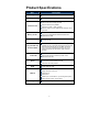
Copyright © 2005 EVGA.com Corporation – All Rights Reserved COPYRIGHT OF THIS MANUAL BELONGS TO THE MANUFACTURER. NO PART OF THIS MANUAL, INCLUDING THE PRODUCTS AND SOFTWARE DESCRIBED IN IT MAY BE REPRODUCED, TRANSMITTED OR TRANSLATED INTO ANY LANGUAGE IN ANY FORM OR BY ANY MEANS WITHOUT WRITTEN PERMISSION OF THE MANUFACTURER. 2 Table of Contents Overview ..................................................................................... 5 Motherboard Features ....................................................................... 5 Preparing Your Computer.................................................................. 6 Package Contents ............................................................................. 6 Product Specifications.............................................................. 7 Chapter 1 .................................................................................... 8 Layout Diagram and Jumper Settings ............................................... 8 Jumpers ........................................................................................ 9 Connectors ................................................................................... 9 Headers ...................................................................................... 10 Expansion Sockets ..................................................................... 10 Chapter 2 .................................................................................. 11 Hardware Installation....................................................................... 11 Hardware installation Steps ........................................................ 11 Checking Motherboard’s Jumper Setting .................................... 11 Installing the AMD Athlon64 754-pin CPU .................................. 13 Installing the Memory.................................................................. 13 Installing Expansion Cards ......................................................... 15 Assigning IRQs for Expansion Card ........................................... 15 Interrupt Request Table for This Motherboard ............................ 16 AGP Slot ..................................................................................... 17 Connectors and Headers............................................................ 18 Starting Up Your Computer ............................................................. 26 Chapter 3 .................................................................................. 27 BIOS Introduction ............................................................................ 27 Entering the BIOS Setup ................................................................. 27 Getting Help Once Inside the BIOS Setup.................................. 27 BIOS Setup Main Menu................................................................... 28 Standard CMOS Features ............................................................... 29 Advanced BIOS Features................................................................ 31 Advanced Chipset Features ............................................................ 34 Integrated Peripherals ..................................................................... 36 Onboard IDE Function ................................................................ 36 Onboard Device Function ........................................................... 38 3 Onboard Super IO Function........................................................ 39 Init Display First .......................................................................... 40 Power On Function ..................................................................... 40 PWR Status after PWR Failure................................................... 40 Power Management Setup .............................................................. 41 PnP/PCI Configuration Setup .......................................................... 43 PC Health Status ............................................................................. 45 Clock/Voltage Control...................................................................... 46 Load Standard and Optimized Defaults........................................... 48 Set Supervisor/User Passwords ...................................................... 48 Save & Exit Setup/Exit Without Saving............................................ 48 Chapter 4 .................................................................................. 49 Motherboard Device Drivers ............................................................ 49 Chapter 5 .................................................................................. 50 Glossary .......................................................................................... 50 Chapter 6 .................................................................................. 51 Useful Information ........................................................................... 51 Contacting Customer Service ..................................................... 51 Information to keep handy before calling .................................... 51 Compliance Information................................................................... 52 FCC Compliance Information...................................................... 52 CE Compliance Information ........................................................ 52 Legal Information............................................................................. 52 Software License Agreement...................................................... 52 Trademark Information ............................................................... 52 Warranty Information ....................................................................... 53 4 Overview Thank you for purchasing a genuine EVGA® motherboard. EVGA is an NVIDIA® Select Solution Provider that builds high performance 3D accelerators and motherboards based on reference designs by the NVIDIA Corporation. Your new EVGA motherboard is fully capable of supporting DPMS (energy savings) and DDC-2B (plug and play) functions. Motherboard Features This motherboard supports 64-bit AMD® Athlon64™ and Sempron™ processors (K8 Processors). The NVIDIA NForce3 250 Chipset delivers a high performance and professional desktop platform solution which utilizes the Socket 754 design. The memory size on this motherboard is expandable to 2.0GB. The EVGA motherboard uses the newest NVIDIA N Force3 250 Chipset which supports an 800MHz system bus. The motherboard provides 133MHz, 166MHz and a 200MHz Memory clock frequency which supports DDR266, DDR333 and DDR400 DDR Module. The motherboard offers ULTRA ATA 133 and Serial ATA RAID 0, RAID 1, RAID 0+1 functions to provide faster HDD performance throughout to boosts overall system performance. The nForce3 has an integrated LAN chip that supports 10, and 100 Mbps data transfer rate for full and half duplex operation. An integrated on-board 6-channel AC’97 CODEC is fully compatible with Sound Blaster Pro that gives the best sound quality and compatibility. For those wanting even greater graphics performance, the 115-K8NF33 is outfitted with an AGP slot supports AGP 8X/4X capability and Fast Write Transactions. This motherboard provides high performance and meets future specification demands. It is wise choice for your computing needs. 5 Preparing Your Computer WARNING: Turn off the power to your system and discharge your body’s static electric charge by touching a grounded surface – for example, the metal surface of the power supply – before performing any hardware procedure. EVGA assumes no liability for any damage, caused directly or indirectly, by improper installation of any components. If you do not feel comfortable performing the installation, consult a qualified computer technician. Damage to system components, such as the motherboard or graphics card, and injury to yourself may result if power is applied during installation. Now that you have prepared your computer, you are ready to install your motherboard. Package Contents EVGA Motherboard Driver Install CD I/O shield for ATX case IDE data cable (2) Floppy drive data cable Serial ATA data cable (2) User Guide 6 Product Specifications Spec Description Design ATX form factor 4 layer PCB, size 30.4x21.0cm. Chipset NVIDIA nForce3 250 single Chipset. Support 64bit AMD Athlon64 754-Pin package utilizes FlipChip Pin Grid Array package processor CPU Socket 754 Support CPU Frequency 800MHz Support up to 3200+ ~ 4000+ processor Reserves support for future AMD Athlon64 Sempron 754-pin processors 184-pin DDR Module socket x 2 Memory Socket Expansion Slot Integrated IDE and Serial ATA RAID Support 2pcs DDR266/DDR33/DDR400 DDR Modules Expandable to 2.0GB AGP slot x1 support AGP 2.0 & AGP 3.0 for 4X/8X mode 32-bit PCI slot x5 Two PCI IDE controllers support PCI Bus Mastering, ATA PIO/DMA and the ULTRA DMA 33/66/100/133 functions that deliver the data transfer rate up to 133 MB/s; Two Serial ATA ports provide 150 MB/sec data transfer rate for two Serial ATA Devices and offer RAID 0, RAID1, RAID 0+1 functions Integrated LAN chip 10/100 LAN Support Fast Ethernet LAN function provide 10/100 Mb/s data transfer rate AC’97 Digital Audio controller integrated Audio 6-channel AC’97 Audio CODEC on board Audio driver and utility included BIOS Award 2MB Flash ROM PS/2 keyboard and PS/2 mouse connectors Floppy disk drive connector x1 Multi I/O Parallel port x1 Serial port x2 USB2.0 port x 4 and headers x 4 (connecting cable option) Audio connector (Line-in, Line-out, MIC) Design ATX form factor 4 layers PCB size: 30.4x21.0cm 7 Jumpers Jumper Name Description Page JP5 CMOS RAM Clear 3-pin Block 11 JP1 Keyboard Power On Enabled/Disabled 3-pin Block 12 USB Power On Enabled/Disabled 3-pin Block 12 JP2/JP6 Connectors Connector Name Description Page ATX Power Connector 20-pin Block 18 ATX 12V Power Connector 4-pin Block 19 PS/2 Mouse & PS/2 Keyboard Connector 6-pin Female 19 USB1/USB2 USB Port Connector 4-pin Connector 19 LAN LAN Port Connector RJ-45 Connector 19 Parallel Port Connector 25-pin Female 19 Audio Connector 3 phone jack Connector 19 COM1/COM2 Serial Port COM1/COM2 connector 9-pin Connector 19 FDD Floppy Driver Connector 34-pin Block 20 IDE1/IDE2 Primary/Secondary IDE Connector 40-pin Block 21 Serial ATA IDE Connector 7-pin Connector 21 PWR ATX12V KB1 PARALLEL CN1 SATA1/SATA2 9 Headers Header Name Description Page SPEAKER, MIC header 9-pin Block 22 USB Port Headers 9-pin Block 22 PC Speaker connector 4-pin Block 23 Power LED 3-pin Block 23 Front Panel Header (including Power LED/ IDE activity LED/Reset Switch / Power On Button lead) 9-pin Block 23 FAN Headers 3-pin Block 24 CDIN CD Audio-In Headers 4-pin Block 24 SPDIF SPDIF Connector 9-pin Block 25 AUDIO USB3 USB4 SPEAK PWR LED FP (Power LED/Reset/ IDE LED/Power Button) SYSFAN1 SYSFAN2 CPUFAN Expansion Sockets Socket/Slot Description Page CPU Socket 754-pin mPGAB Athlon64 CPU Socket 13 DDR Module Socket 184-pin DDR Module Socket 14 PCI1∼ PCI5 PCI Slot 32-bit PCI Local Bus Expansion slots 15 AGP AGP 4X/8X Mode Slot AGP Expansion Slot 16 ZIF Socket 754 DIMM1 Name DIMM2 10 Chapter 2 Hardware Installation Hardware installation Steps Before using your computer, complete the following steps: 1. Check the motherboard jumper settings. 2. Install the CPU, heatsink and fan. 3. Install the system memory (DIMM). 4. Install any expansion cards that are to be used in the system. 5. Connect the IDE and floppy cables as well as the front and back panel cables. 6. Connect ATX power supply cable. 7. Power-On and load the standard default motherboard settings. 8. Reboot the system. 9. Install the Operating System. 10. Install any drivers and utility software as needed. Checking Motherboard’s Jumper Setting 9 JP5 – CMOS RAM Clear (3-pin) A battery must be used to retain the motherboard configuration in CMOS RAM short 1-2 pins of JP5 to store the CMOS data. To clear the CMOS, follow the procedure below: 1. Turn off the system and unplug the AC power 2. Remove ATX power cable from ATX power connector 3. Locate JP5 and short pins 2-3 for a few seconds 4. Return JP5 to its normal setting by shorting pins 1-2 5. Connect ATX power cable back to ATX power connector Note: The CMOS should be cleared when troubleshooting, forgetting a password or after over clocking and the system failed to boot. 1 3 1 JP5 1-2 closed Normal 2-3 closed CMOS RAM Clear Setting 11 3 JP5 Clear CMOS 9 JP1 – Keyboard Power On function Enabled/Disabled JP1 JP1 1 1 3 3 1-2 closed - KB Power ON Disable (Default) 2-3 closed - KB Power ON Enabled Keyboard/USB Power On Setting 9 JP2, JP6 – USB Power On function Enabled/Disabled JP2 JP2 1 1 3 3 1-2 closed USB Power ON Disable (Default) 1 2-3 closed USB Power On Enabled 1 3 JP6 1-2 closed USB Power ON Disable (Default) 2-3 closed USB Power On Enabled USB Power On Setting 12 3 JP6 Installing the AMD Athlon64 754-pin CPU This motherboard provides a 754-pin surface mount, Zero Insertion Force (ZIF) socket, referred to as the mPGA754 socket which supports the AMD Athlon64 processor in the 754 Pin package utilizes Flip-Chip Pin Grid Array package technology. The CPU that comes with the motherboard should have a cooling FAN attached to prevent overheating. If this is not the case, purchase the correct cooling FAN before turning on the system. WARNING: Be sure that there is sufficient air circulation across the processor’s heatsink. In addition, ensure the CPU cooling FAN is working correctly; otherwise it may cause the processor and motherboard to overheat which could cause damage to the system. An auxiliary cooling FAN may be installed if necessary. To install the CPU, follow the procedures below: 1. Turn off your system and remove its cover. 2. Locate the ZIF socket and open it by first pulling the lever sideways away from the socket then upward to a 90-degree angle. 3. Insert the CPU with the correct orientation as shown below. 4. Replace the lever to its original position. Note: Locate the notched corner and place the CPU in the socket accordingly. Because the CPU has a corner pin for two of the four corners, the CPU will only fit in the orientation as shown. Golden Arrow Socket 754 CPU ZIF mPGAB Socket Installing the Memory This motherboard has two 184-pin DDR Dual Inline Memory Modules (DIMM) slots for DDR memory. The minimum memory size for this motherboard is 64MB and expands to a maximum memory size of 2.0GB of DDR SDRAM. 13 Valid Memory Configurations: Bank 184-pin DDR DIMM PCS Total Memory Bank 0, 1 (DIMM1) DDR266/DDR333/DDR400 DDR DRAM Module X1 64MB∼1.0GB Bank 2, 3 (DIMM) DDR266/DDR333/DDR400 DDR DRAM Module X1 64MB∼1.0GB System Memory (Max. 2.0GB) X2 64MB∼2.0GB Total Installing DDR SDRAM modules in to the motherboard is generally easy; however, if you need assistance, refer to the illustration below. DIMM1 (BANK0+BANK1) DIMM2 (BANK2+BANK3) Note: When you install DIMM modules fully into the DIMM socket, the eject tab should be locked into the DIMM module and fit into its indention on both sides. WARNING: The DDR SDRAM CLOCK is set at 200MHz; use only DDR400 compliant DDR Modules. If non-compliant DIMM modules are used, the system may not boot because of the strict timing requirements. If the DDR Modules are not DDR400 compliant, set the SDRAM clock to 133MHz to ensure system stability. 14 Installing Expansion Cards WARNING: Turn off the power to the system when adding or removing expansion cards or any other system components. Failure to do so may cause severe damage to the system. Installation Procedures: 1. Read the documentation that came with the expansion card and make any necessary hardware or software setting changes for the expansion card. A good example is jumper setting changes. 2. Remove the computer’s cover and the bracket plate on the slot you intend to use. 3. Align the card’s connectors and press it in firmly. 4. Secure the card in the slot with the screw that was removed from the bracket plate. 5. Replace the computer system’s cover. 6. Set up the BIOS if necessary. 7. Install any necessary software drivers for the new expansion card. Assigning IRQs for Expansion Card Some expansion cards need an IRQ to operate. Generally, an IRQ must exclusively be assigned to the expansion card for it to work properly. In a standard design, there are 16 IRQs available but most of them are already in use. 15 9 - These IRQs are usually available for ISA or PCI devices. IRQ Priority Standard function 0 N/A System Timer 1 N/A Keyboard Controller 2 N/A Programmable Interrupt 3 4 5 6 7 9 9 9 9 9 10 11 12 9 9 9 9 13 14 15 Communications Port (COM2) 9 Communications Port (COM1) 6 Sound Card (sometimes LPT2) 11 Floppy Disk Controller 7 8 9 8 Printer Port (LPT1) N/A System CMOS/Real Time Clock 10 ACPI Mode when enabled 3 IRQ Holder for PCI Steering 2 IRQ Holder for PCI Steering 4 PS/2 Compatible Mouse Port N/A 9 9 Numeric Data Processor 5 Primary IDE Channel 1 Secondary IDE Channel Interrupt Request Table for This Motherboard Slot Slot 1 Slot 2 Slot 3 INT A INT B INT C INT D INT E INT G INT H 9 9 9 9 Slot 4 9 9 Slot 5 Onboard USB 1 9 Onboard USB 2 AC97/MC97 INT F 9 IMPORTANT! If using PCI cards on shared slots, make sure that the drivers support “Shared IRQ” or that the cards do not need an IRQ assignment. If conflicts arise between the two PCI groups, it will make the system unstable or cards inoperable. 16 AGP Slot This motherboard is equipped with an AGP Slot that supports 8X/4X AGP VGA cards. 2X 4X AGP SLOT 17 Connectors and Headers Connectors PWR: Power Connector (20-pin block) ATX Power Supply Connector – The motherboard is setup for soft power on by using the momentary switch that connects from the front panel switch to the 2-pin Power On jumper on the motherboard. When the power switch on the back of the ATX power supply is turned on, the full power will not come into the system board until the front panel switch is momentarily pressed. Pressing the switch again will turn off the power to the motherboard. PIN 1 ROW 1 3.3V ROW 2 3.3V 2 3.3V -12V 3 GND GND 4 5V Soft Pow er On 5 GND GND 6 5V GND 7 GND GND 8 Pow er OK -5V 9 +5V (for Soft Logic) +5V +12V +5V 10 Pin 1 ATX12V: ATX 12V Power Connector (4-pin block) This motherboard has a supplemental power connector that delivers an additional 12V volts for processors that require additional power. If the 4-pin power connector is not connected to the motherboard, the system can become unstable and not function properly. Pin 1 18 KB1: PS/2 Mouse & PS/2 Keyboard Connector These are connectors for the PS/2 keyboard and the PS/2 Mouse. USB1/USB2: USB Port connector These are 4-pin connectors that connect USB devices to the system board. LAN: LAN Port connector This is a standard RJ45 connector which allows connectivity to a network. PARALLEL: Parallel Port Connector (25-pin female) The Parallel Port connector is a 25-pin D-Subminiature Receptacle connector. The On-board Parallel Port can be disabled through the BIOS SETUP. Please refer to INTEGRATED PERIPHERALS SETUP section for more detail information. CN1: AUDIO (LINE-OUT, LINE-IN, MIC): Audio and Game Connector Line-Out: Audio output to speakers. Line-In: Audio input to the sound chip. MIC: Connects a Microphone to the system COM1/COM2: Serial Ports These are 9-pin D-Subminiature male connectors. The On-board serial ports can be disabled through the BIOS SETUP MENU. Please refer to the INTEGRATED PERIPHERALS SETUP section for more details regarding this information. PS/2Mous PRINT USB1 LAN MIC LINE-IN LINE-OUT PS/2 KB COM1 19 COM2 USB2 FDD: Floppy drive Connector (34-pin block) This connector supports the 3 ½ inch floppy drive ribbon cable. Use the cable provided to connect the floppy drive to the system motherboard. FDD Pin 1 Floppy Drive Connector IDE1: Primary IDE Connector (40-pin block) This connector supports the IDE1 hard disk ribbon cable. Use the cable provided to connect the primary hard drive to the system motherboard. Note: If two hard disks are installed, the second drive must configured as a slave by setting its jumpers accordingly. Please refer to the documentation of the hard disk for the correct jumper settings. IDE1 Pin 1 Primary IDE Connector 20 IDE2: Primary IDE Connector (40-pin block) This connector supports the IDE2 hard disk ribbon cable. Use the cable provided to connect the primary hard drive to the system motherboard. IDE2 Pin 1 Secondary IDE Connector Two hard disks can be connected to each connector. The first HDD is referred to as the Master and the second HDD is referred to as the Slave. For performance issues, we strongly suggest that CD-ROM drives or DVD-ROM drives are NOT installed on the same IDE channel. This can produce a drop in system performance. SATA1/SATA2: Serial-ATA Port connector This connector supports the provided Serial ATA hard disk cable. Use the cable to connect the Serial ATA hard disk to the motherboard. SATA1 SATA2 Serial-ATA Port Connector 21 Headers AUDIO: Line-Out/MIC Header for the Front Panel (9-pin) Some case manufactures supply audio connectors built into the front of the case. This header will allow a cable to be connected from the motherboard to those built in connectors. This header connects to the front panel Line-Out and the MIC. Without the cable installed, this headers default jumper setting are 5-6 short and 9-10 short. When you install the cable, you must remove these jumpers. AUDIO Pin 1 2 AUD_GND AUD_VCC AUD_RET_R AUD_MIC AUD_MIC_BIAS AUD_FPOUT_R HP_ON AUD_FPOUT_L AUD_RET_L 9 10 Line-Out, MIC Headers VCC -DATA +DATA GND OC VCC +DATA GND Pin 1 USB4 -DATA +DATA GND OC VCC USB3 -DATA USB3/USB4: USB Port Headers (9-pin) These headers are used for connecting an additional USB port plug. By attaching the optional USB cable, two additional USB plugs can be affixed to the back panel. +DATA GND VCC -DATA Pin 1 USB Port Headers 22 SPEAK: Speaker connector This 4-pin connector connects to the case-mounted speaker. PWR LED: Power LED The Power LED is illuminated while the system power is on. Connect the Power LED from the system case to this pin. HD LED: IDE Activity LED This connector connects to the hard disk activity indicator light on the case. RESET: Reset switch lead This 2-pin connector connects to the case-mounted reset switch for rebooting the system without having to turn off your power switch. This is a preferred method of rebooting in order to prolong the lift of the system’s power supply. See the figure below. PWRLED Pin 1 SPEAK JW FP PWRBTN GND PWRLED PWRBTN VCC5 PWR LED PWR BTN: Power switch This 2-pin connector connects to the case-mounted power switch to power ON/OFF the system. Pin 1 VCC5 HDDLE GND RSTSW NC HDLED RESET GND VCC5 SPKR NC Pin 1 System Case Connections 23 SYSFAN1, SYSFAN2, CPUFAN: FAN Headers (3-pin) These connectors support cooling fans of 350mA (4.2 Watts) or less, depending on the fan manufacturer, the wire and plug may be different. The red wire should be positive, while the black should be ground. Connect the fan’s plug to the board taking into consideration the polarity of connector. 1 CPUFAN 3 1 SYSFAN 3 1 3 SYSFAN CDIN: CD Audio-In Headers (4-pin) CDIN are the connectors for CD-Audio Input signal. Please connect it to CD-ROM CD-Audio output connector. CDIN 4 1 CD Audio-In Headers 24 SPDIF SPDIF-OUT GND CENTER GND SPDIF: SPDIF IN/OUT Headers (9-pin) 10 2 Pin 1 12V SURROUT SURROUT SPDIF-IN BASS 9 SPDIF In/Out Header 25 Starting Up Your Computer 1. 2. 3. 4. 5. 6. After all connections have been made and any expansion cards have been installed, close the computer case and fasten the cover. Be sure all switches are off, and confirm that the power supply input voltage is set to proper position, usually in-put voltage is 220V∼240V or 110V∼120V depending on your country’s voltage. Connect the power supply cord to the back of the power supply unit located on the back of the system case. Turn on the peripherals in following order: The monitor Other external peripheral (e.g. Printer, Scanner, External Modem) Power on the system. In most cases, the ATX power switch is located on the front of the case. The power LED on the front panel of the system case will illuminate. The LED on the monitor may light up or switch between orange and green after the system has started. The system will then run self tests. Note: Notice any beeps or messages that appear on the screen. These are used to notify users of any alarms that need to be addressed during start-up. In the event the screen is black and nothing appears within 30 seconds from the time you turn on the power, the system may have failed and was unable to perform the power-on test. If this is the case, recheck your jumper settings and all connections to the motherboard. Beep Meaning No short beep when displaying the logo. No errors during post. Long beeps in an endless loop. One long beep followed by 3 short beeps. High frequency beeps with system is working. 7. No DRAM installed or detected. Video card not found. CPU is overheating / System running at a lower frequency. During power-on, press the DELETE key to enter BIOS Setup Menu. Follow the instructions in BIOS Setup section of this manual. 26 Chapter 3 BIOS Introduction The BIOS is a program that lives in the flash memory of the motherboard. This program acts a bridge between the motherboard and the operating system. When the computer is started, the BIOS performs a self test called POST (Power On Self Test) and runs through a series of auto diagnostic tests. These tests are checking the hardware and configuring the parameters for synchronization. Once the POST has been completed, the computer will start the Operating System (OS) and allow the user to start using the computer. Since the BIOS is the only channel for hardware and software to communicate, it is the key factor for system stability ensuring that the system performance is at its best. In the BIOS Setup Main Menu, there are several options to choose from when configuring the system. These options will be explained step by step in the following pages of this chapter. Below is a short description of the function keys that will be used to navigate through the BIOS menu. Press the ESC key to quit the BIOS Setup. Press the ↑↓←→ (up, down, left, right) arrow keys, from the main menu, to select the categories that need to be modified. Press the F10 key to Exit and Save the changes that were made to the BIOS. Press the Page Up/Page Down keys to modify the BIOS parameters for the active option. Entering the BIOS Setup Enter the BIOS Setup by pressing the DEL key just before the system starts to POST. In the event the DEL key was not pressed in-time, restart the system and try again. This can be done by pressing the Reset button on the front of the system case or by turning the power OFF and then ON. Pressing CTRL + ALT + DEL keys simultaneously will also restart the system. Getting Help Once Inside the BIOS Setup Once inside the BIOS Setup, the F1 key can be pressed to popup a small help window that that describes the appropriate keys to use and the possible selections for the highlighted item. To exit the Help Window, press ESC. 27 BIOS Setup Main Menu Once inside the Award® BIOS CMOS Setup Utility, the Main Menu will appear with fourteen setup functions and two exit choices. Use arrow the keys to navigate through the items and press ENTER to select the desired function. See Figure 3.1 below. Figure 3.1 Standard CMOS Features Select this option for basic system configurations. Advanced BIOS Features This is used to set the Advanced Features available on your system. Advanced Chipset Features Select this option to change the values in the chipset register and as well as optimize the system’s performance. Integrated Peripherals This is to specify the settings for integrated peripherals. Power Management Setup Select this option to specify the settings for power management. PnP/PCI configurations This entry appears if the system supports PnP/PCI. PC Health Status Select the option to show the health of the PC status. Clock/Voltage Control Select this option to specify the settings for miscellaneous controls such as clock speeds and voltages. 28 Load Optimized Defaults This will load the BIOS’s default values. These settings are used for optimal system performance. Load Standard Defaults This will load the BIOS’s default values for a stable system operation. These are the factory settings for normal use. Set Supervisor/User Password This will allow a Supervisor or an Administrator to setup User and Supervisor Passwords. Save & Exit Setup Save CMOS value changes to CMOS and exit setup. Exit Without Saving Abandon all CMOS value changes and exit setup. Standard CMOS Features The items in the Standard CMOS Setup Menu are divided into several categories. Use the arrow keys to highlight category, then use the PgUp /PgDn keys to select the values to be change. For an example of the Standard CMOS Features menu, see the example below. Figure 3.2 Date The date format is as follows: Day: This value ranges from Sunday through Saturday and is automatically changed as the values below are entered. Month (mm): Change this value to the appropriate month. This value ranges from January through December. Date (dd): Change this value to the appropriate date. Values range from 1 to 31. These can also be keyed in by using the numeric key pad. 29 Year (yy): Change this value to the appropriate year. Time The time format is as follows (Military Time is represented here): Hours (hh): Change this value to represent the appropriate time, hours. The range for value is 00 through 24. Minutes (mm): Change this value to the appropriate time, minutes. The range for this value is 00 through 59. Seconds (ss): Change this value to the appropriate time, seconds. The range for this value is 00 through 59. IDE Channel 0 Master 0 Slave 1 Master 1 Slave 2 Master 3 Master Navigate to each of the appropriate drives for configuration. Once selected, hit ENTER to bring up the IDE Channel configuration menu. From there, the IDE HDD Auto Detection function can be used to detect and setup the selected drive pressing the ENTER key. Each channel can also be setup individually by navigating to the IDE Channel 0 Master, or which ever drives is being setup at the time. In this example 0 Master was selected. Use the PgUp /PgDn keys to configure the hard drive(s). The values for this setting are Manual, Auto and None. Note: The specifications of the hard drive must match with the drive table within the BIOS. The hard disk(s) will not work properly if incorrect information is set for this selection. If the hard disk drive type is not matched or listed, use the Manual option to define the hard drive type. If the Manual option is selected, necessary related information must be provided. Enter the information directly from the keyboard. This information should be provided in the documentation from the hard disk vendor or the system manufacturer. If the controller of HDD interface is SCSI, the selection will be None. If the controller of HDD interface is a CD-ROM, the selection will be None. 30 Change the following to match the hard disk settings when entering in this information manually. Refer for the hard drive manufacturer documentation for details. Access Mode: The settings for this item are: Auto CHS, LBA and Large. Cylinder: Provide the number of cylinders for the hard drive. Head: Provide the number of heads for the hard drive. Precomp: Enter the Write Precomp value. Landing Zone: Enter the Landing Zone value. Sector: Provide the number of sectors. Drive A Select the appropriate device for Drive A. Set this function to one of the configuration options: None, 360K/5.25in, 1.2M/3.5in, 370k/3.5in, 1.44M/3.5in or 2.88M/3.5in. Video Select the appropriate video device. Set this function to one of the configuration options: EGA/VGA, CGA 40, CGA 80 or Mono. Halt On This setting determines at which point the boot up process will be stopped in the event errors happen to occur. Set this function to one of the configuration options: All Errors, No Errors, All But KB, All But Diskette or All But Disk/Key. Advanced BIOS Features The following information is provided as a reference for the Advanced BIOS Features of this motherboard. See Figure 3.3 below. Figure 3.3 Anti-Virus Protection This feature provides a WARNING in the event if an attempt is made to write data to the IDE hard disk boot sector. If enabled, a warning 31 message will appear on screen and an audible alarm sound indicating an attempt has been made to write data to this area of the boot sector. Disabled (default) – No warning message will appear when attempts to access the boot sector or hard disk partition table. Enabled – Activates automatically when the system boots up causing a warning message to appear when attempts to access the boot sector of the hard disk partition table have been made. CPU L1 Cache/CPU L2 Cache Since cache memory is much faster than conventional DRAM system memory, these fields allow users to enable or disable the CPU’s Level 1 internal cache and Level 2 external cache. Set this function to one of the configuration options: Enabled or Disabled. Enabled is default for both settings. Quick Power On Self-Test This option determines the type of POST (Power On Self Test) that will be ran during the system startup. If this option is set to Enabled (Quick POST), the BIOS skips some of the self tests that are run during POST. Set this function to one of the configuration options: Enabled or Disabled. Hard Disk Boot Priority Under this section, all of the systems drives will be listed. First, Second, Third, Other Boot Device This option sets the sequence of drives the BIOS attempts boot from and load the operating system after the POST completes. Once POST is complete, the BIOS will search the drives for an operating system. Set this function to one of the configuration options: Floppy, LS120, Hard Disk, CD-ROM, Zip100, USB-FDD, USB-Zip or USB-CD-ROM. Boot Up Floppy Seek This is a self check to ensure the floppy drive’s power is on after starting the computer system. Set this function to one of the configuration options: Enabled or Disabled. Boot Up NumLock Status This option determines if the Num Lock key pad will be enabled during system startup. The configuration for this item is as follows: On (default), numeric keypad is functional when the operating system starts and, Off, numeric keypad is not functional when the operating system starts, only the four arrow keys function. Gate A20 Option Gate A20 refers to the way the system addresses memory above 1 MB (extended memory). When set to Fast, the system chipset controls Gate A20. When set to Normal, a pin in the keyboard controller controls Gate A20. Setting Gate A20 to Fast improves system speed, particularly with OS/2 and Windows. 32 Typematic Rate Setting Keystrokes repeat at a rate determined by the keyboard controller. When enabled, the Typematic Rate and Typematic Delay can be selected. This option is either Enabled or Disabled. Typematic Rate (Chars/Sec) This option sets the number of times a second to repeat a keystroke when a key is held down. Set this function to one of the configuration options: 6, 8, 10, 12, 15, 20, 24, or 30. Typematic Delay (Msec) This sets the delay time after the key is held down before it begins to repeat the keystroke. Set this function to one of the configuration options: 250, 500, 750 or 1000. Security Option If a password is set, select whether the password is required every time the System boots, or only when users enter Setup. Set this function to one of the configuration options: Setup (default) or System. APIC Mode APIC (Advanced Programmable Interrupt Controller) Mode was developed to comply with the PC2001 standard. By enabling APIC Mode, the system increases the availability of IRQ resources. Set this function to one of the configuration options: Enable or Disable. MPS Version Control For OS This item allows users to select which MPS (Multi-Processor Specification) version is used for the operating system. The BIOS supports versions 1.1 and 1.4 of the Intel multiprocessor specification. Select the version supported by the operating system running on this system. OS Select For DRAM > 64MB Select OS2 only if the system is running the OS/2 operating system and has greater than 64MB of RAM. Set this function to one of the configuration options: OS2 or Non-OS2. HDD S.M.A.R.T Capability Self Monitoring Analysis and Reporting Technology (S.M.A.R.T.) is a technology that enables the BIOS early detection and warning of a possible failure of storage devices such as hard disk drives. Set this function to one of the configuration options: Enabled or Disabled. Report No FDD For Windows Set this option to No if the system is not running a floppy drive. The configuration options for this setting are Yes and No. 33 Advanced Chipset Features The Advanced Chipset Features setup option is used to change the values of the chipset registers. These registers control most of the system options in the computer. See Figure 3.4 below. Figure 3.4 DRAM CAS Latency When synchronous DRAM is installed, the number of clock cycles of CAS latency depends on the DRAM timing. Set this function to one of the configuration options: Auto, 2.0, 2.5 or 3.0. Unless the CAS Latency is known, Auto should be selected. SDRAM RAS-to-CAS Delay This field allows for a timing delay between the CAS and RAS strobe signals, used when DRAM is written to, read from, or refreshed. Set this function to one of the configuration options: Auto, 2, 3, 4, 5, 6 or 7. The Default setting for this function is Auto. SDRAM Cycle Time The Default and recommended setting for this function is Auto. System performance can be improved if adjusted; however, system instability may occur if this setting is not set to the proper value. SDRAM RAS Precharge Time If an insufficient number of cycles are allowed for the RAS to accumulate its charge before DRAM refresh, the refresh may be incomplete and the DRAM may fail to retain data. If this item is set to a smaller increment, the system yields faster performance; however, if the item is set to a larger number, the system yields more stable performance. This field applies only when synchronous DRAM is installed in the system. Set this function to one of the configuration options: Auto, 2, 3, 4, 5 or 6. The Default setting for this function is Auto. 1T/2T Memory Timing This feature sets the memory timing for the system. Set this function to one of the configuration options: Auto, 1T and 2T. 34 AGP Aperture Size Select the size of the Accelerated Graphics Port (AGP) aperture. The aperture is a portion of the PCI memory address range dedicated for graphics memory address space. Host cycles that hit the aperture range are forwarded to the AGP without any translation. Set this function to one of the configuration options: 32M, 64M, 128M, 256M or 512M. AGP 3.0 Speed This setting is Enabled if an AGP 3.0 graphics card is detected by the system. AGP 2.0 Speed This option is for configuring the AGP bus speed. Set this function to one of the configuration options: Auto, 1x, 1x2x or 1x2x4x. AGP Fast Write Selecting auto for this feature will allow the Fast Write Protocol to function (AGP 8X/4X). Set this function to one of the configuration options: Auto or Disabled. Note: Not all AGP cards support Fast Write. AGP Sideband Address Configuring this option determines the bus address between AGP card and CPU. Set this function to one of the configuration options: Auto or Disabled. HT Frequency Set this function to one of the configuration options: 1X, 2X, 3X, 4X or 5X. Special I/O for PCI Card The purpose of this item is to allocate specific addresses for specific PCI cards. The configuration settings for this option are Enabled or Disabled. If enabled, Base I/O Address and I/O Length will also have to be configured. System BIOS Cacheable Selecting Enabled allows caching of the system BIOS ROM at F0000hFFFFFh resulting in better system performance. However, if any program writes to this memory area, a system error may result. Set this function to one of the configuration options: Enabled or Disabled. 35 Integrated Peripherals The information contained in this part of the CMOS Setup Utility provides details on setting up the peripheral devices for the system. See the Figure 3.5. Figure 3.5 Onboard IDE Function The following information is provided as a reference for the Onboard IDE Function of the BIOS. Below is an illustration of the menu for this section. See Figure 3.6. Figure 3.6 OnChip IDE Channal0/Channel1 The integrated peripheral controller contains an IDE interface with support for two IDE channels. Select Enabled to activate each channel separately. Set this function to one of the configuration options: Enabled or Disabled. 36 Primary/Secondary Master/Slave PIO The four IDE PIO (Programmed Input/Output) fields set the PIO mode (0-4) for each of the four IDE devices that the onboard IDE interface supports. Modes 0 through 4 provide successively increased performance. In Auto mode, the system automatically determines the best mode for each device. Set this function to one of the configuration options: Auto, Mode 0, Mode 1, Mode 2, Mode 3 or Mode 4. Primary/Secondary Master/Slave UDMA Ultra DMA/33 implementation is possible only if the IDE hard drive supports it and the operating environment includes a DMA driver (Windows 95 OSR2 or a third-party IDE bus master driver). If the hard drive and the system software both support Ultra DMA/33 and Ultra DMA/66, select Auto to enable BIOS support. Set this function to one of the configuration options: Auto or Disabled. Primary/Secondary Master/Slave RAID Configure the RAID controllers accordingly. The setting for this option is Enabled or Disabled. IDE Prefetch Mode The onboard IDE drive interfaces support IDE prefetching, for faster drive accesses. If a primary and or secondary add-in IDE interfaces are installed, set this field to Disabled if the interface does not support prefetching. Set this function to one of the configuration options: Enabled or Disabled. IDE DMA Transfer Access This setting is for the standard controllers on the motherboard, configuring it accordingly. Set this function to one of the configuration options: Enabled or Disabled. IDE HDD Block Mode Block mode is also called block transfer, multiple commands, or multiple sector read/write. If the IDE hard drive supports block mode (most new drives do), select Enabled for automatic detection of the optimal number of block read/writes per sector the drive can support. Set this function to one of the configuration options: Enabled or Disabled. SATA Controller This item determines if the SATA Controller is functional, configuring it accordingly. Set this function to one of the configuration options: Enabled or Disabled. SATA DMA Transfer This item selects the DMA mode for devices connected through SATA channels. Set this function to one of the configuration options: Enabled or Disabled. SATA Primary/Secondary Master RAID These items set the SATA Primary and Secondary Master RAID devices. Set this function to one of the configuration options: Enabled or Disabled 37 Onboard Device Function The following information is provided as a reference for the Onboard Device Function of the BIOS. Below is an illustration of the menu for this section. See Figure 3.7. Figure 3.7 AC97 Sound Device Set this option to Enabled to use the on-board AC97 Audio features. The configuration options for this setting are Auto, Enabled and Disabled. nVIDIA LAN Function Set this option to Enabled to use the on-board 250 LAN feature. The configuration options for this setting are Auto, and Disabled. MAC Media Interface Use this item to set the MAC Media Interface feature. The configuration options for this setting are Pin Strap, MII and RGMI. LAN MAC Address Input This feature allows the user to enter the MAC Address of the network. USB Host Controller This item controls the USB support on the motherboard. If Enabled is selected, the USB 2.0 Support option and the USB KB/Storage Support option can be configured. USB 2.0 Support - Select Enabled if the system contains a Universal Serial Bus (USB) 2.0 controller and will be used. Set this function to one of the configuration options: Enabled or Disabled. USB KB/Storage Support - Select Enabled if the system contains a Universal Serial Bus (USB) controller and will have a USB keyboard attached. Set this function to one of the configuration options: Enabled or Disabled. 38 Onboard Super IO Function The following information is provided as a reference for the Onboard Super IO Function of the BIOS. Below is an illustration of the menu for this section. See Figure 3.8. Figure 3.8 Onboard FDD Controller Select Enabled if the system has a floppy disk controller (FDD) installed and will be used. If an add-on Floppy Disk Controller will be installed or the system has no floppy drive, select Disabled. Set this function to one of the configuration options: Enabled or Disabled. Onboard Serial Port 1/Port 2 Select an address and a corresponding interrupt for the first and the second serial ports. Set this function to one of the configuration options: 3F8/IRQ4, 2E8/IRQ3, 3E8/IRQ4, 2F8/IRQ3, Disabled or Auto. UART Mode Select This function allows the user to select an operating mode for the second serial port. The configuration settings for this item are Normal, IrDA, ASKIR or SCR. IR Duplex Mode – This feature becomes available when either IrDA or ASKIR is selected. The available options for this setting are Full or Half Duplex. Onboard Parallel Port Select the LPT port address and corresponding interrupt for the physical parallel port. Set this function to one of the configuration options: Disabled, 3BC/IRQ7, 278/IRQ5 or 378/IRQ7. 39 Parallel Port Mode Select an operating mode for the onboard parallel (printer) port. Select SPP unless the hardware and software both support one of the other available modes. The options for this setting are SPP, EPP, ECP and ECP+EPP. Note: To operate the onboard parallel port as a Standard Parallel Port ONLY, select SPP. To operate the onboard parallel port in the Extended Parallel modes simultaneously, choose EPP. By selecting ECP, the onboard parallel port will operate in ECP mode only. Choosing ECP+EPP will allow the onboard parallel port to support both the ECP and EPP modes at the same time. The ECP mode has to use the DMA channel, so select the onboard parallel port with the ECP feature. After it has been selected, the following message will appear, “ECP Mode Use DMA.” At this time, the user can choose between DMA channels 3 to 1. Since the onboard parallel port is EPP Spec. compliant, so after the user chooses the onboard parallel port with the EPP function, the following message will be displayed on the screen: “EPP Mode Select.” At this time either EPP 1.7 spec. or EPP 1.9 spec. can be chosen. ECP Mode Use DMA: This item automatically specifies DMA channel 1 or 3 for the parallel port when it is set to EPP or ECP+EPP. Init Display First This function allows user to determine which display will initialize when the system starts. Set this function to one of the configuration options: AGP or PCI Slot. Power On Function This function determines by which method the system will be started. Set this function to one of the configuration options: Password, Hot Key, Any Key or Button Only. Password – A password must be correctly entered in order to wake-up the system so that it can be used. The KB Power ON Password function will be enabled and the password will be entered here during setup. Hot Key – A hotkey combination can be entered in order to wake the system up so that it can be used. The Hot Key Power ON function has twelve hotkey combinations to select. The configuration options for this setting are CTRL-F1 through CTRL-F12. PWR Status after PWR Failure This function determines what the system will do in the event of a power failure. The options for this setting are Always Off, Always On and Former Status. 40 Power Management Setup The Power Management Setup allows for the most effective power saving configurations while operating the PC in a manner consistent with users own style of computing needs. Below is an illustration of the menu for this section. See Figure 3.9. Figure 3.9 ACPI Function This item allows users to Enabled or Disabled the Advanced Configuration and Power Management (ACPI) functions. Set this function to one of the configuration options: Enabled or Disabled. ACPI Suspend Type This item specifies the power saving modes for the ACPI Function. Set this function to one of the configuration options: S1 (POS), S3 (STR) or S1 & S3. S1 (POS) - S1 is for the low power state. There is no system context (CPU or Chipset) lost and the hardware maintains all system contexts. S3 (STR) - S3 is a lower power state, where the information of system configuration and opened applications / files are saved to main memory. The remaining power of other hardware components are turn off to save energy. The information stored in memory will be used to restore the system. S1 & S3 - If S3 state is supported by the system, by default S3 is automatically selected otherwise S1 is chosen. 41 Video Off Method This function determines the manner in which the monitor is blanked. The configuration options for this function are DPMS, Blank Screen and V/H SYNC+Blank. DPMS (default) - Initial display power management signaling. Blank Screen - This option only writes blanks to the video buffer. V/H SYNC+Blank - This selection will cause the system to turn off the vertical and horizontal synchronization ports and write blanks to the video buffer. Power Button Function This function allows users to set the action of the power button. If set to Delay 4 Sec, it will cause the computer sleep mode if the power button is held in for at least 4 seconds. The configuration settings are Delay 4 Sec and Instant-Off. Wake-Up On PCI PME When this function is set to Enabled, any event happening from a PCI card (PME) will awaken the system from being powered down. Set this function to one of the configuration options: Disabled or Enabled. Wake-Up on Ring/LAN When this function is set to Enabled, any event affecting from a modem ring or LAN activity will awaken a system that has powered down. Set this function to one of the configuration options: Disabled or Enabled. USB Resume from S3/S4/S5 When this function is set to Enabled, any event affecting from the onchip USB will awaken a system that has powered down state of S3, S4 or S5. Set this function to one of the configuration options: Enabled or Disabled. Wake-Up on RTC Alarm This option is for setting up a date and time for the computer to boot up automatically. Day of Month Alarm: Sets the date in which the computer will automatically start. Select which month the system will boot up. Set to 0, the computer will boot every day. Time (hh:mm:ss) Alarm: Set the hour, minutes and seconds (hh:mm:ss) when the computer is scheduled to start. AMD K8 Cool ‘n’ Quiet Control When this option is set to Auto, it reduces processor power consumption without degrading system performance. The settings for this function are Auto and Disabled. 42 PnP/PCI Configuration Setup This section describes configuring the PCI bus system. PCI, or Personal Computer Interconnect, is a system which allows I/O devices to operate at speeds nearing the speed the CPU itself uses when communicating with its own special components. This section covers some very technical items and it is strongly recommended that only experienced users should make any changes to the default settings. Below is an illustration of the menu for this section. See Figure 3.10. Figure 3.10 Reset Configuration Data Typically, this field Disabled. Set this function to Enabled to reset the Extended System Configuration Data (ESCD). This would be done when you exiting Setup and a new add-on has been installed and the system reconfiguration has caused such a serious conflict that the operating system cannot boot. Set this function to one of the configuration options: Enabled or Disabled. Resource Controlled By The Award Plug and Play BIOS has the capability to automatically configure all bootable and Plug and Play compatible devices; however, this capability means absolutely nothing unless a Plug and Play operating system such as Windows®95/98/XP is installed. If this field is set to Manual, specific resources have to be selected by going into each of the sub menus and selecting them for the corresponding interrupts. Set this function to one of the configuration options: Auto (ESCD) or Manual. 43 IRQ Resources - When resources are controlled manually, each system interrupt must be assigned a corresponding IRQ number. The corresponding IRQ type is dependant upon the type of device that requires the interrupt. The settings for this function are PCI Device and Reserved. See Figure 3.11 below. PCI/VGA Palette Snoop Leave this field at Disabled. Figure 3.11 44 PC Health Status This section shows the over all health Status of the system. From this section of the CMOS Setup Utility Menu, users can monitor current system temperatures, voltages, CPU FAN as well as System FAN operating speeds. Below is an illustration of the menu for this section. See Figure 3.12. Figure 3.12 Shutdown Temperature This option allows users to set the shutdown temperature of the processor in the event the system overheats. When the CPU temperature reaches an unacceptable temperature, the processor will automatically shutdown to protect itself. Set this function to one of the configuration options: Disabled, 60°C/140°F, 65°C/149°F or 70°F/158°F. Show PCHealth in POST Set to Enabled, this feature displays the health of the PC during POST of the initial system startup. Set this function to one of the configuration options: Enabled or Disabled. 45 Clock/Voltage Control Use this section to setup and configure the CPU Frequency and Voltage Controls. Below is an illustration of the menu for this section. See Figure 3.13. Figure 3.13 WARNING: This motherboard has features which allow users to overclock. Before any adjustments to the defaults settings are made, please make sure your peripherals are able to tolerate abnormal settings. Any attempt to operate this product beyond the default specifications is not recommended. EVGA is NOT responsible for damage caused by inadequate operation or settings beyond the product specifications. CPU Clock at next Boot is This option is to setup the CPU frequency, in MHz, using single incremental steps. The configuration options for this item are 200MHz 250MHz. AGP Clock at next Boot is This option is to setup the AGP frequency, in MHZ, using single incremental steps. The configuration options for this item are 66MHz 100MHz. Mem Clock at next Boot is This field displays the capability of the memory modules that can be used. Set this function to one of the configuration options: Auto, 100, 133, 166 or 200. VDIMM/VDDQ Over Voltage This item is used to enable the VDIMM and the VDDQ Over Voltage controls. Set this function to one of the configuration options: Enabled or Disabled. VDIMM Select 46 This item is used to select the VDIMM voltage. If the VDIMM Over Voltage is enabled, the options for this selection are 2.55V, 2.65V(Default), 2.75V or 2.85V. If the previous option is disabled, the settings are 2.50V, 2.60V(Default), 2.70V and 2.8V. VDDQ Select This item is used to select the VDDQ voltage. If the VDDQ Over Voltage is enabled, the options for this selection are 1.55V(Default), 1.65V, 1.75V or 1.85V. If the previous option is disabled, the settings are 1.50V(Default), 1.60V, 1.70V and 1.80V. Vcore Over Voltage This item is used to set the Vcore Voltage for the processor. The selections for this item are Disabled, +50mV, +100mV and +150mV. Hammer FID Select The configuration settings for this option are Default (Recommended), X4 800MHz – X12 2400MHz in 200MHz increments. Hammer Vcore Select The configuration settings for this option are Default (Recommended), 1.550V – 0.825V in 25V increments. 47 Load Standard and Optimized Defaults Load Standard Defaults This option loads the BIOS defaults that are the most stable with minimal system performance. Load Optimized Defaults This option loads the BIOS factory settings that are the most stable with optimal system performance. Set Supervisor/User Passwords Set Supervisor Password Only individuals who have a supervisor password, typically System Administrators, will be able to enter the system BIOS and change the values once they have provided the correct password. Set User Password Individuals who are assigned a user password ONLY have the ability to enter the BIOS. They are unable to make any changes to the BIOS settings. Save & Exit Setup/Exit Without Saving Save & Exit Setup This option saves the changes made to the BIOS and exits the BIOS setup menu. Exit Without Saving This option exits the BIOS setup menu without saving any changes were made to the BIOS. Figure 3.14 48 Chapter 4 Motherboard Device Drivers To begin using the nForce3 Motherboard Driver CD, insert it into the CD-ROM drive. The CD will automatically display the device drivers menu if Autorun is enabled on the system. See Figure 4.1 below. Note: In the event Autorun is not enabled, navigate to the CD-ROM Drive within Windows® Explorer and double click the autorun.exe icon. Once the Device Drivers Menu appears, select the item(s) that are to be installed on the system. Figure 4.1 Install Motherboard Drivers This Item installs the NVIDIA Chipset Drivers for the nForce3 Chipset. This includes the LAN driver as well as the IDE driver. Install Audio Drivers This item installs the ALC AC97’ Codec Audio Divers for the onboard sound. Install USB 2.0 Drivers This item installs the USB 2.0 Drivers. This requires Windows® XP Service Pack 1 or higher. Install NVIDIA nTune™ Software This enables the easiest, safest, and highest performing overclocking available for NVIDIA nForce-based PCs. Install Acrobat® Reader® This item installs the Acrobat Reader. It is required to view the PDF version of the CD Manual. View CD Manual This item brings up the PDF version of the user’s manual. 49 Chapter 5 Glossary Chipset (or core logic) - two or more integrated circuits which control the interfaces between the system processor, RAM, I/O devises, and adapter cards. Processor slot/socket - the slot or socket used to mount the system processor on the motherboard. Slot (AGP, PCI, ISA, RAM) - the slots used to mount adapter cards and system RAM. AGP - Accelerated Graphics Port - a high speed interface for video cards; runs at 1X (66MHz), 2X (133MHz), or 4X (266MHz), or 8X (533MHz). PCI - Peripheral Component Interconnect - a high speed interface for video cards, sound cards, network interface cards, and modems; runs at 33MHz. Serial Port - a low speed interface typically used for mouse and external modems. Parallel Port - a low speed interface typically used for printers. PS/2 - a low speed interface used for mouse and keyboards. USB - Universal Serial Bus - a medium speed interface typically used for mouse, keyboards, scanners, and some digital cameras. Sound (interface) - the interface between the sound card or integrated sound connectors and speakers, MIC, game controllers, and MIDI sound devices. LAN (interface) - Local Area Network - the interface to your local area network. BIOS (Basic Input/Output System) - the program logic used to boot up a computer and establish the relationship between the various components. Driver - software, which defines the characteristics of a device for use by another device or other software. Processor - the "central processing unit" (CPU); the principal integrated circuit used for doing the "computing" in "personal computer" Front Side Bus Frequency - the working frequency of the motherboard, which is generated by the clock generator for CPU, DRAM and PCI BUS. CPU L2 Cache - the flash memory inside the CPU, normal it depend on CPU type. 50 Chapter 6 Useful Information Contacting Customer Service EVGA is dedicated to supporting our products. Contacting EVGA Customer Service is easy! We can be reached by phone, fax, and on the web. Before contacting Customer Service, please review this manual. If you need to contact Customer Service, please have your system configuration as well as your motherboards model number and serial number ready. You will need to register your product before a support technician can assist you. You may register your card online at: http://www.evga.com/register, or when you call for support a staff member will register you. Hours of Operation: 9AM to 5PM Monday to Friday, PST Phone Support: (888) 881-EVGA (3842) Fax Support: (714) 528-4501 Tech Support Web Site: http://www.evga.com/support Information to keep handy before calling Motherboard Model Number: Motherboard Chipset: Processor Type and Speed: Operating System and Version (Service Packs installed, if any): Installed Hardware: 51 Compliance Information FCC Compliance Information This device complies with FCC Rules Part 15. Operation is subject to the following two conditions: This device may not cause harmful interference, and this device must accept any interference received, including interference that may cause undesired operation. This equipment has been tested and found to comply with the limits for a Class B digital device, pursuant to Part 15 of the FCC Rules. These limits are designed to provide reasonable protection against harmful interference in a residential installation. This equipment generates, uses and can radiate radio frequency energy and, if not installed and used in accordance with manufacturer’s instructions, may cause harmful interference to radio communications. However, there is no guarantee that interference will not occur in a particular installation. If this equipment does cause harmful interference to radio or television reception, which can be determined by turning the equipment off and on, the user is encouraged to try to correct the interference by one or more of the following measures: Increase the separation between the equipment and signal source. Connect the equipment to an outlet on a circuit different from that to which the signal source is connected. Consult the dealer or an experienced computer technician for help. The use of shielded cables for connection of the monitor to the graphics card is required to ensure compliance with FCC regulations. Changes or modifications to this unit not expressly approved by the party responsible for compliance could void the user’s authority to operate this equipment. CE Compliance Information EMC Directive 89/336/EEC and Amendment 92/31/EEC, Class B Digital Device EN 50081-14, Generic Emissions Standard for Residential, Commercial and Light Industrial Products (EN 55022/CISPR 22, Limits and Methods of measurement of Radio). (EN 55022/CISPR 22, Limits and Method of Measurement of Radio Interference Characteristics Information Technology Equipment) Warning: This is a Class B product. In a domestic environment this product may cause radio interference in which case the user may be required to take adequate measure. EN 50082-1, Generic Immunity Standard for Residential, Commercial and Light Industrial Products (IEC 801-2, IEC 801-3, IEC 801-4) Legal Information Software License Agreement Single User Products The EVGA ADM software (the “Software”) is copyrighted by EVGA.com Corp. and is is protected by U.S. Patent Number 6, 832, 312. All rights are reserved. The purchaser is granted a license to use the Software only, subject to the following restrictions and limitations: 1. 2. 3. 4. The license is for the original purchaser only, and is not transferable without written consent from EVGA. The original purchaser may use the Software on a single computer owned or leased by the original purchaser. You may not use the Software on more than a single machine, even if you own or lease more than one machine, without written consent from EVGA. The original purchaser may make backup copies of the Software for his or her own use only, subject to the use limitations of this license. The original purchaser may not engage in, nor permit third parties to engage in, any of the following: Providing or disclosing the Software to third parties. Providing use of the Software in a computer service business, network, time –sharing, multiple CPU or multi-user arrangement to users who are not individually licensed by EVGA Making alterations or copies of any kind in the Software (except as specifically permitted above). Attempting to unassemble, de-compile or reverse engineer the Software in any way. Granting sublicenses, leases, or rights in the Software to others. Making copies, or verbal or media translations, of the user’s guide. Making telecommunication data transmissions of the Software. Trademark Information 2001-2005 EVGA.com Corp. EVGA, the EVGA logo and combinations thereof are trademarks of EVGA.com Corp. NVIDIA, NVIDIA Logo, nForce are registered trademarks and/or trademarks of NVIDIA Corporation in the United States and other countries and are used under license to EVGA.com Corporation from NVIDIA Corporation. AMD is a registered trademark of Advanced Micro Devices. All brands and companies are trademarks of registered Trademarks of their respective companies. EVGA reserves the right to terminate this license if there is a violation of its terms or default by the Original Purchaser. Upon termination, for any reason, all copies of the Software must be immediately returned to EVGA and the Original Purchaser shall be liable to EVGA.com Corp. for any and all damages suffered as a result of the violation or default. 52 Warranty Information 53