1
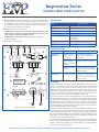
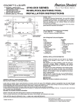
Impression Series
SUBWOOFER USER’S GUIDE
Introduction
Congratulations on your purchase of an Impression Series Subwoofer! Your subwoofer is the result of many years of research and development dedicated to producing powerful,
accurate bass in home audio systems. This manual contains operating procedures and specifications. We recommend you thoroughly read through the material contained in this
manual before connecting your subwoofer. This will ensure you have an understanding of how to setup and operate your subwoofer for optimum performance.
Safety Instructions
IMPORTANT NOTICE REGARDING BASS MANAGEMENT: It is important the
signal being sent to the subwoofer be a non-boosted or “flat” signal. To be sure of
this, check the settings on your receiver or processor to make sure any “bass boost”,
“super bass” or “loudness” is set to Off. In most cases a home theater receiver or
processor will determine the crossover frequency through bass management settings.
In this configuration, connect the receiver or processor to the Line Level Input. Your
subwoofer will now reproduce the bass frequencies the way they were originally
recorded. Use the subwoofer level control and the individual bass management
control within the receiver or processor to adjust the subwoofers’ volume if necessary.
Once set, the volume controls should not need to be altered as the subwoofer’s volume
will track with the master volume control of your receiver or processor.
The lightning flash with the arrowhead symbol within an equilateral triangle, is intended to
alert the user to the presence of un-insulated “dangerous voltage” within the product enclosure
that may be of sufficient magnitude to constitute a risk of shock to persons.
The exclamation point within an equilateral triangle is intended to alert the user to the
presence of important operating and maintenance (servicing) instructions in the literature
accompanying the product.
When using your subwoofer, basic safety precautions should always be followed to reduce
the risk of fire, electric shock, and injury.
1. Read and understand all instructions in the users manual before operating the
Subwoofer and retain this user manual for future reference.
2. Follow all warnings and instructions in this manual and any marked
on the back of the Subwoofer.
3. Never touch the woofers or push objects of any kind into the woofer.
4. The subwoofer should be connected to a power supply compatible with the
power consumption requirements, see the specifications section of this manual.
5. If mounting the subwoofer on a stand, the wall, or other device only do so as
recommended by an authorized technician.
6. Place the subwoofer a safe distance from all heat sources such as radiators,
stoves, or heaters.
7. Do not operate the subwoofer near water—for example, near a bathtub,
kitchen sink or in a wet basement; or a swimming pool.
8. Power supply cords should be routed so they are not likely to be walked
on or pinched by items placed upon or against them.
9. Any service or repair required must be performed by qualified,
authorized technician.
Break In Period
Allow several hours of listening time to adequately break-in the subwoofer. During
the break-in period, the driver suspension will loosen. The result of break-in will be
an increase in low frequency response, improved definition, and increased clarity
and detail.
Setup Suggestions
In order to obtain the best possible sound from your subwoofer, it is important to determine where the subwoofer will sound best in your listening room. Sound reflections
from the floor, ceiling and side walls influence the balance, imaging and overall sonic
quality at the listening position. Experiment with subwoofer placement to determine
which location offers the best overall sound.
Placement of the subwoofer will largely determine quality, quantity and extension
of the bass frequencies within your listening room. Bass frequencies are reinforced
by close room boundaries. Placing the subwoofer in a corner will make the subwoofer
sound louder and boost the very lowest frequencies.
Placing the subwoofer away from walls will provide the least reinforcement, making
the bass sound subjectively thinner than if the woofer were closer to a wall. Good
results can usually be obtained by placing a subwoofer along a wall 1-3 feet from a
corner. Experiment with placement of the subwoofer and the sub-amplifier controls
to achieve the proper bass balance.
Amplifier Controls and Setup
This section describes the functions and/or use for each of the amplifier controls located
on the back of the subwoofer. See the reverse side of this sheet for diagram.
1. Voltage Selector Switch: Before connecting the amplifier to any power source make
sure the AC Voltage Selector is set to either 110V or 220V to match the power voltage
in your area.
WARNING! If the voltage setting does not match the AC power supplied, damage
to the Subwoofer Amplifier may result.
2. Volume/Gain Control: The volume/level control should be at the minimum setting
(all the way counter-clockwise) before plugging the subwoofer into an AC wall socket.
Once plugged in, turn the level control up one quarter of a turn (9 o’clock position)
for an initial setting. The level control may be adjusted while playing to match the
subwoofer level with the rest of the system.
IMPORTANT! The volume control should be at the minimum setting (all the way
counter-clockwise) before plugging the subwoofer into an AC wall socket.
3. Crossover Frequency Control: The variable crossover frequency control
allows you to set the low-pass crossover point of the subwoofer anywhere from
40-180 Hz. If using this input experiment with setting the crossover frequency control
at highest setting initially. Increasing the crossover frequency will allow more midbass output from the subwoofer. Decreasing the frequency will allow only deeper
bass from the subwoofer.
NOTE: Read the Important Notice regarding bass management above.
4. Auto Signal Tracking: The subwoofer amplifier uses “smart” signal tracking circuitry.
Once the power cord is plugged in and the switch set to on, the amplifier automatically
turns on when a signal is detected at the preamplifier or high level inputs and turns off
when no signal has been detected for 15 minutes.
5. Phase Control: This control changes the phase of the subwoofer. Changing the phase
will change the way the subwoofer and main speakers interact with each other at the
crossover frequency. Varying the phase position may result in more or less mid bass
depending on the phasing between the main speakers and the subwoofer. Generally,
the phase is left at the “NOR (Normal)” position.
6. Low Level Line Output: These RCA terminals are for “daisy chaining” to another
subwoofer or amplifier. A full-range signal is sent through these terminals.
7. Low Level Line Input: Line level input is used to connect to most receivers or processors,
use either the L or R terminals.
8. Hi-Level Input: These binding post terminal connections are for the amplifier/speaker
level input from an amplifier or receiver.
IMPORTANT! Use either the Line Input or the High Level Input. DO NOT use them
both simultaneously.
For assistance, please call 801-991-1308 or check http://www.emptek.com for updated instructions.
Impression Series
SUBWOOFER USER’S GUIDE
9. Hi-Level Output: This is a 100 Hz high-passed output for your satellite/main
speakers. The crossover limits the low frequencies (below 100 Hz) from going to
your satellite/main speakers. This crossover is active only when using the Hi-Level
Input terminals. Connect your main speakers (observing the proper polarity) to
these terminals when using the Hi-Level Inputs.
Specifications
Model
ES10i Subwoofer
Frequency Response:
40Hz – 180Hz
10. Fuse Access: This is the power fuse access.
Amplifier Power:
100 Watts (110V Only!)
Woofer:
(1) 10” (254mm) Poly-matrix Cone
Crossover Frequencies:
40Hz – 180Hz (Low Pass)
Dimensions: (Includes Base)
141/8” (359mm) W
15” (381mm) H
161/4” (413mm) D
Cabinet Color:
High-gloss Red Burl or Black Wood
Weight:
27 lbs. (12.25 Kg)
WARNING! In the event the fuse must be replaced, the replacement fuse must
match exactly the original fuse value. If the replacement fuse is not of the same
value, damage to the Subwoofer Amplifier may result.
CAUTION! Before replacing the fuse, disconnect the power cord from
the power receptacle.
11. Power: Power on and off switch.
Troubleshooting
Situation:
Probable Cause:
Solution:
No sound from
subwoofer(s)
Amplifier is not connected to constant
power outlet.
Make certain the amplifier is
plugged into an unswitched AC
power outlet.
Amplifier is not
receiving an audio
signal from receiver or
processor
Make certain there is an audio
signal from receiver or processor.
Amplifier fuse might
be blown.
Replace fuse (if fuse is not readily
accessible, consult your authorized
RBH Sound dealer).
Crossover frequency
not adjusted correctly.
Adjust the crossover frequency by
turning the crossover frequency
control clockwise until the desired
sound is obtained.
Performance is less
than expected
Warranty
Impression Series Subwoofer Diagram.
Engineered Music Products “EMP Tek” warrants all EMP speakers and subwoofers (the
“Product”) are covered by a limited warranty against defects in materials and workmanship for a period of 5 (five) years on the woofer and cabinet, and 1 (one) year on the
amplifier from the original date of purchase from an authorized EMP Tek dealer or the
EMP Tek website. This warranty extends only to the original consumer purchaser. EMP
Tek does not warrant goods used in industrial applications. This warranty does not cover
any expenses incurred in any removal or re-installation of the product.
If the product should prove defective within the warranty period, contact EMP Tek for a
return authorization number prior to returning the product by prepaid delivery to EMP
Tek, along with the original sales invoice or other proof of purchase, which establishes
eligibility for warranty service. EMP Tek will, at its option, replace or repair the product
free of charge and return the product by prepaid delivery. This warranty does not apply to
any product which has been damaged, misused, altered, neglected or repaired by anyone
other than an EMP Tek authorized service facility.
Any implied warranties including fitness for use and merchantability are limited in duration to the period of the express warranties set forth above, and no person is authorized to
assume for EMP Tek any other liability in connection with the sale of the product. EMP
Tek expressly disclaims liability for any incidental and consequential damages caused
by the product or the result of failure of this product. The remedies provided under this
warranty are exclusive and in lieu of all others.
This warranty gives specific legal rights. In addition, there may be other legal rights arising
from the sale of the product, which vary from state to state. Some states do not allow the
exclusion or limitation of incidental or consequential damages, so the above limitation
or exclusion may not apply in some areas.
For assistance, please call 801-991-1308 or check http://www.emptek.com for updated instructions.