1
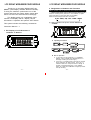
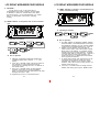
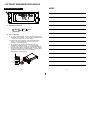
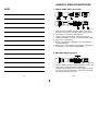
LCD DISPLAY
WIRELESS RECEIVER MODULE
Instruction Manual
Electronics Co., Ltd.
Head office: 8 1 4 , P e i - K a n g R o a d , C h i a y i , 6 0 0 , T a i w a n .
Taipeioffice:5,Lane 118, S ung-teh Road, Taipei, 110, Taiwan.
Web-http: //www.mipro.com.tw
E-mail: [email protected]
2CE097
B
0681
0197
interstage
Phistersvej 31, 2900 Hellerup, Danmark
Telefon 3946 0000, fax 3946 0040
www.interstage.dk
- pro audio with a smile
LCD DISPLAY WIRELESSRECEIVER MODULE
Thank y o u for choosing MIPRO'sACT-707
MB/MC (LCD Display Wireless Receiver Module).
To bring the maximum performance out of the
system and know the system better, please take
user's time and read this instruction thoroughly.
The display panel is a modularized monocolored LCD display that c a n display various
information o f operation and perform ACT feature.
This system includes the following accessories:
Instruction Manual × 1
LCD DISPLAY WIRELESSRECEIVER MODULE
2. Designations of buttons and Functions
MENU: Enable user to select from one functiontotheother
"MENU" button allows user to select a mong 6 options (in the
sequence showing below) thateach is surroundedin a square
frame and shown on the upper half of LCD display.
Detail functionsandoperationsare as follows.
G/CH→FREQ→SQ→VOL →NAME →REMO
(1) G/CH: Indicates o r s e t u p s t h e receiver GROUP a nd
CHANNEL.
1. Full Display o f L C D Screenand
Locations of buttons
A. Operating Procedures.
MENU
G/CH
GROUP
DOWN
MENU
CHANNEL
DOWN
UP
UP
MENU
EXIT
Save
B. How to Operate?
a. In the lowerrow ofLCDdisplay, T V CHANNEL,
GROUP, and C HANNELare separatelyshown in
dual-digit numbers(fromlefttoright).
b. Push"UP" or " DOWN" button once and the number
above "GROUP" will start b linking. Push "UP" or
"DOWN" button now will permituserto change to
another pre-programmed group. Push "MENU"
button to confirm the modification andgroupnumber
will stop blinking.
-1-
-2-
LCD DISPLAY WIRELESSRECEIVER MODULE
c. Repeatthe same process as above for "CHANNEL"
and verify themodification by pushing "MENU"
button and channel number w ill stop blinking.
LCD DISPLAY WIRELESSRECEIVER MODULE
A. Operating P rocedures.
MENU
SQ
(2) FREQ: Indicates the frequency that is currently in use.
MENU
01
DOWN
UP
EXIT
save
B. How to Operate?
a. User can set thesquelchlevel within the range of
01-99.
b. To set the squelchlevel,simplyby pushing the "UP"
or "DOWN" buttonandconfirm the modification by
pushing "MENU" button.
(4) VOL: Indicates Volume Level i s a t O n o r M ute p osition.
A. Operating Procedures.
MENU
FREQ
B. How to Operate?
a. After push "MENU" button and select the "FREQ"
frame, it w ill show the frequency that is s e t u n d e r
the GROUPand CHANNEL that one had selected
previously.
b. This function cannot b e used for frequency
alternation.
(3) SQ: Indicates or setups the Squelch level.
Switching From Audible To Mute
A. Operating P rocedures.
MENU
VOL
MUTE
DOWN
EXIT
UP
B. How to Operate?
Push "UP" o r "DOWN" Button a l l o w s o n e t o switch
volume to"ON"or"Mute"status.
-3-
-4-
LCD DISPLAY WIRELESSRECEIVER MODULE
C. CAUTIONS :
AF bar and A n t . A , B of LCD panel will n ot
displayedwhen the receiver module is at Mute status.
To ascertain if receiver is at Mute status, press Menu
key,selectVolume. If LCD indicates"Mute" it is a Mute
status. If LCDindicates "On" a u d i o i s operating
normally.
LCD DISPLAY WIRELESSRECEIVER MODULE
(6) REMO: Indicates o r setupthe receiveraddress a n d
status of remotecontrolling.
(5) NAME: Indicates or setupsthename of current channel
user.
A. Operating P rocedures.
MENU
REMO
DOWN
A. Operating Procedures.
MENU
NAME
MENU
DOWN
UP
MENU
A
UP
NEXT
EXIT
Save
B. How to Operate?
a. Maximum 6 characters areallowed (Select from
capitalized English letter, numbers, + - x / , and
space).
b. Push "UP" or "DOWN" button into s e t u p m o d e a n d
the character on thefar leftwillstartblinking.
(There will be n o blinking if t h e r e i s no character in
the specific space).
c. Push "UP" or "DOWN" button to select desired
character and confirm by pushing the"MENU"
button. Onceconfirmed, the nextcharacter will start
blinking a n d r e a d y f o r setup.
save
a. ACT-BUS interface is adapted for MIPRO Wireless
Receiver Module. With MIPROInterface Converter
and Monitoring Software, up to 64 receiver modules
canberemote-controlledsimultaneously viaa P C.
b. Address canbe setwithin the range of01-64.
Under remote control mode, each receiver module
MUSThasits own address. If 2 d ifferent receiver
modules are u s i n g t h e same address, it will cause
confliction and result in monitoring error. However, if
not under remote control mode, operation will
remainnormal even i f 2 differentreceivermodules
areusing thesameaddress.
c. In remote cont rol mode, "ON" will beshownin the
LCDdisplaypanel and the number next to the
message is the address of the receiver module.
However, "OFF" will b e shown is t h e s y s t e m i s not
remotely linked to the PC.
d. Push"UP" or " DOWN" button to change receiver
address and verifybypushingthe "MENU" button.
d. Repeat step c u n t i l A L L 6 charactersareset.
-5-
UP
EXIT
B. How to Operate?
DOWN
A
MENU
64
-6-
LCD DISPLAY WIRELESSRECEIVER MODULE
NOTE﹕
Operation of ACT Feature:
A. Operating Procedures.
ACT
ACT
EXIT
B. How to Operate?
a. At LCD panel displays "Group" and "Channel" mode
keystroke "ACT" button . ACT mode is activated when
" ACT" word a ppears on the LCD panel.
b. Position the "ACT" marking of the transmitter a bout
30cm ( 12-inch) towards the "ACT"buttononthe
receiver. (see below figure)
c. ACT function will release a utomatically once the
transmitter channel i s l o c k e d on. Simultaneously,
"Group" and " Channel" mode willbe back showing on
the LCD panel. Both transmitter and receiver should
show the same"Group" and"Channel". This indicates
transmitter frequency set-up is successful. If
unsuccessful, repeat step " A".
GROUP CHANNEL B A T
ACTSERIES
ACT
-7-
-8-
HANDHELD WIRELESS MICROPHONE
NOTE﹕
1. PARTS NAME AND FUNCTIONS
G R O U P CHANNEL
1
2
3
BAT
4
G R O U P CHANNEL
BAT
5
6
7
(Fig.1)
1. Grille: Protects cartridge, prevents "POP" noise and
prevents microphonefrom rolling withpolygonal shape.
2. Color Ring: For frequency differentiation.
3. Housing: Upper portion to be connectedtocapsule
module and battery. Internally, it holds transmitter PCB.
4. Functions of LCD Display
5. Battery Compartment: Designed to accommodatetwo
1.5V(AA) batteries.
6. Battery Cap: Covers battery in the battery compartment.
7. Anti-roll Ring: For frequency differentiation.
2. BATTERY INSTALLATIONS
G R O U P C H A N N E L BAT
(Fig.2)
1. Unscrew battery capinacounter-clockwise direction (6).
2. Insert two1.5V(AA) batteries into thebattery
compartment according to the correct polarity as shown
in Fig.2.Themomentthebattery touches the terminals,
the indicator will flashbriefly (6).
-9-
- 10 -
HANDHELD WIRELESS MICROPHONE
3. FUNCTIONS OFLCDDISPLAY
HANDHELD WIRELESS MICROPHONE
4. Battery Status:
GROUP CHANNEL BAT
ERR
1. ERR Message: When "ERR" appears, it means "Error
with the system" Please refer to the following codes
to diagnose which error you are experiencing.
ERR no01→EEPROM is not being programmed or
internal data error.
ERR no02→Testing only.
ERR no03→The frequency you are about to program
into the system exceeds microphone's
upper limit. (At this time, microphone is
still operatable and the frequency remains
unchanged. To clear to "ERR" message
in LCD display, simply turns off the power
and switch back on.)
100%
80%
40%
0%
Battery Status: When the battery has less than 10%
power remaining, LED indicator will lit to remind you to
replace the battery. If undervoltage, LCD will show
"PoFF" and shut down the system to avoid battery being
over-discharged.
5. Switch Off:
When switch the power knob to "Off" position, LCD
will show "PoFF" first. Then, the system is completely
shut down and no further message will be displayed.
ERR no04→The frequency you are about to program
into the system is below microphone's
frequency lower limit. (At this time,
microphone is still operatable and the
frequency remains unchanged. To clear
to "ERR" message in LCD display, simply
turns off the power and switch back on.)
2. "Group" & "Channel " : When both items are shown,
they indicate that the user is currently using the preprogrammed frequency in the receiver.
3. "Channel" Only : If "Channel" is the only item shown in
the display, it indicates the user is using the
personalized frequency. (Such frequency can only be
programmed via MIPRO's ACT Software and available
for ACT-707B and ACT-707C only.)
- 11 -
10%
- 12 -
HANDHELD WIRELESS MICROPHONE
3. FUNCTIONS OFLCDDISPLAY
HANDHELD WIRELESS MICROPHONE
4. Battery Status:
GROUP CHANNEL BAT
ERR
1. ERR Message: When "ERR" appears, it means "Error
with the system" Please refer to the following codes
to diagnose which error you are experiencing.
ERR no01→EEPROM is not being programmed or
internal data error.
ERR no02→Testing only.
ERR no03→The frequency you are about to program
into the system exceeds microphone's
upper limit. (At this time, microphone is
still operatable and the frequency remains
unchanged. To clear to "ERR" message
in LCD display, simply turns off the power
and switch back on.)
100%
80%
40%
0%
Battery Status: When the battery has less than 10%
power remaining, LED indicator will lit to remind you to
replace the battery. If undervoltage, LCD will show
"PoFF" and shut down the system to avoid battery being
over-discharged.
5. Switch Off:
When switch the power knob to "Off" position, LCD
will show "PoFF" first. Then, the system is completely
shut down and no further message will be displayed.
ERR no04→The frequency you are about to program
into the system is below microphone's
frequency lower limit. (At this time,
microphone is still operatable and the
frequency remains unchanged. To clear
to "ERR" message in LCD display, simply
turns off the power and switch back on.)
2. "Group" & "Channel " : When both items are shown,
they indicate that the user is currently using the preprogrammed frequency in the receiver.
3. "Channel" Only : If "Channel" is the only item shown in
the display, it indicates the user is using the
personalized frequency. (Such frequency can only be
programmed via MIPRO's ACT Software and available
for ACT-707B and ACT-707C only.)
- 11 -
10%
- 12 -
BELT PACK TRANSMITTER
NOTE﹕
1. PARTS NAME AND FUNCTIONS
BAT
LOW
1
ON
OFF
2
3
4
5
G R O U P CHANNEL BAT
6
ACTSERIES
7
8
11
9
10
GAIN
MT GT
(Fig.1)
1. AF Input Jack: Connects to either lavaliere or headset
microphone. (See 5 ways of connection on AF Input
Connections)
2. Power Switch: Switch to ON position for operation.
Switch to OFF position when not in use.
- 13 -
- 14 -
BELT PACK TRANSMITTER
3. Battery Status Indicator: Indicates the power on / off
and battery status.
(a) When power switch is turned on: The LED
indicator flashes briefly, indicating normal battery
status.
(b) When RED light illuminates at either power on or
during usage: The battery level is low, therefore, a
new battery replacement is thus necessary.
4. Transmitting Antenna: 1/ 4 λ transmitting antenna.
5. Transmitter Housing: Packages the PCB and battery.
6. Functions of LCD Display
7. Act Signal Receptor
8. Gain Control: Adjusts the desirous input gain.
9. GT/MT Level Select Switch: Switch GT position for
electric guitar usage and "Line In". Gain Control is
irrelevant for "GT". Switch to "MT" for condenser
microphone or wired microphone. Gain Control works
in "MT" for input sensitivity adjusting.
10.Battery Compartment and Cover: Accommodates two
1.5V(AA) batteries.
BELT PACK TRANSMITTER
2. OPERATING INSTRUCTIONS
1. To adjust GT/MT Switch (10), and Gain Control (8),
simply push down both snap locks on the sides of
battery cover and flip it backwards to expose the
adjustment panel.
2. Before power on, ascertain if same channel (7) was
set up for both receiver and microphone. If not adjust
to same channel accordingly.
3. The LED indicator flashes briefly when power on
indicating normal battery status. If no flash occurs it
has either no battery, the battery is drained or
installed incorrectly. Change accordingly.
4. Plug the microphone connector into the input jack (1)
and tighten the connector screw by clockwise direction
as shown in (Fig. 2).
CapsuleConnectort
Headset
Lavalier
Pleaseaimof
thefillister
andinsertthe
connector
11. Detachable Belt Clip: Allows 360 degrees rotating to
suit transmitting angles. To detach simply use a
screwdriver at a 45 degree angle to unfasten. see
diagram.
(Fig.2)
- 15 -
- 16 -
BELT PACK TRANSMITTER
3. AF INPUT C O NNECTIONS
BELT PACK TRANSMITTER
4. FUNCTIONS OFLCDDISPLAY
GROUP CHANNEL
(1) 2-Wire Electret condenser microphone Capsule
BAT
ERR
SHIELD
PIN
1
AUDIO
2
3
4PIN
PLUG
4
(2) 3-Wire Electret condenser microphone Capsule
SHIELD
PIN
1
2
AUDIO
3
BIAS
4PIN
PLUG
4
(3) Dynamic Microphone
2
1
SHIELD
PIN
1
3
2
AUDIO
3
4PIN
PLUG
4
(4) Electric Guitar
SHIELD
PIN
1
2
AUDIO
3
4
4PIN
PLUG
(5) Line-in (Impedance 8KΩ ATT. 10dB)
SHIELD
AUDIO
PIN
1
2
1. ERR Message: When "ERR" appears, it means "Error
with the system" Please refer to the following codes
to diagnose which error you are experiencing.
ERR no01→EEPROM is not being programmed or
internal data error.
ERR no02→Testing only.
ERR no03→The frequency you are about to program
into the system exceeds microphone's
upper limit. (At this time, microphone is
still operatable and the frequency remains
unchanged. To clear to "ERR" message
in LCD display, simply turns off the power
and switch back on.)
ERR no04→The frequency you are about to program
into the system is below microphone's
frequency lower limit. (At this time,
microphone is still operatable and the
frequency remains unchanged. To clear
to "ERR" message in LCD display, simply
turns off the power and switch back on.)
2. "Group" & "Channel " : When both items are shown,
they indicate that the user is currently using the preprogrammed frequency in the receiver.
3. "Channel" Only : If "Channel" is the only item shown in
the display, it indicates the user is using the
personalized frequency. (Such frequency can only be
programmed via MIPRO's ACT Software and available
for ACT-707B and ACT-707C only.)
3
4
4PIN
PLUG
- 17 -
- 18 -
BELT PACK TRANSMITTER
BELT PACK TRANSMITTER
5. BATTERY INSTALLATION
4. Battery Status:
1. Pushing down both snap locks on the sides of battery
cover to open battery cover. Take out the batteries.
Fig.(2).
100%
80%
40%
10%
0%
2. Insert a two 1.5(AA) batteries into the battery
compartment according to the correct polarity as
shown in Fig. (3). Then push up to close the battery
compartment as shown in Fig. (3).
Battery Status: When the battery has less than 10%
power remaining, LED indicator will lit to remind you to
replace the battery. If undervoltage, LCD will show
"PoFF" and shut down the system to avoid battery being
over-discharged.
5. Switch Off:
When switch the power knob to "Off" position, LCD
will show "PoFF" first. Then, the system is completely
shut down and no further message will be displayed.
(Fig.2)
(Fig.3)
- 19 -
-20-
BELT PACK TRANSMITTER
BELT PACK TRANSMITTER
5. BATTERY INSTALLATION
4. Battery Status:
1. Pushing down both snap locks on the sides of battery
cover to open battery cover. Take out the batteries.
Fig.(2).
100%
80%
40%
10%
0%
2. Insert a two 1.5(AA) batteries into the battery
compartment according to the correct polarity as
shown in Fig. (3). Then push up to close the battery
compartment as shown in Fig. (3).
Battery Status: When the battery has less than 10%
power remaining, LED indicator will lit to remind you to
replace the battery. If undervoltage, LCD will show
"PoFF" and shut down the system to avoid battery being
over-discharged.
5. Switch Off:
When switch the power knob to "Off" position, LCD
will show "PoFF" first. Then, the system is completely
shut down and no further message will be displayed.
(Fig.2)
(Fig.3)
- 19 -
-20-
LCD DISPLAY
WIRELESS RECEIVER MODULE
Instruction Manual
Electronics Co., Ltd.
Head office: 8 1 4 , P e i - K a n g R o a d , C h i a y i , 6 0 0 , T a i w a n .
Taipeioffice:5,Lane 118, S ung-teh Road, Taipei, 110, Taiwan.
Web-http: //www.mipro.com.tw
E-mail: [email protected]
interstage
Phistersvej 31, 2900 Hellerup, Danmark
Telefon 3946 0000, fax 3946 0040
www.interstage.dk
2CE097
B
- pro audio with a smile
0681
0197