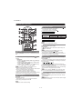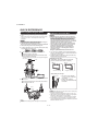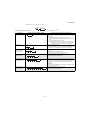
1
TopPage LC-40D68UT SERVICE MANUAL No. S40F340D68UT/ LCD COLOR TELEVISION MODEL LC-40D68UT In the interests of user-safety (Required by safety regulations in some countries) the set should be restored to its original condition and only parts identical to those specified should be used. CONTENTS SAFETY PRECAUTION IMPORTANT SERVICE SAFETY PRECAUTION ............................................................i PRECAUTIONS A PRENDRE LORS DE LA REPARATION ...............................................ii PRECAUTIONS FOR USING LEAD-FREE SOLDER ........................................................... iii OUTLINE MAJOR SERVICE PARTS ................................iv CHAPTER 1. SPECIFICATIONS [1] SPECIFICATIONS ......................................... 1-1 CHAPTER 2. OPERATION MANUAL [1] OPERATION MANUAL .................................. 2-1 CHAPTER 4. REMOVING OF MAJOR PARTS [1] REMOVING OF MAJOR PARTS...................4-1 CHAPTER 5. ADJUSTMENT [1] ADJUSTMENT PROCEDURE ......................5-1 [2] PUBLIC MODE SETTING PROCEDURE ......5-25 CHAPTER 6. TROUBLESHOOTING TABLE [1] TROUBLESHOOTING TABLE ......................6-1 CHAPTER 7. OVERALL WIRING/BLOCK DIAGRAM [1] OVERALL WIRING DIAGRAM ......................7-1 [2] SYSTEM BLOCK DIAGRAM .........................7-2 Parts Guide CHAPTER 3. DIMENSIONS [1] DIMENSIONS ................................................ 3-1 Parts marked with " " are important for maintaining the safety of the set. Be sure to replace these parts with specified ones for maintaining the safety and performance of the set. This document has been published to be used for after sales service only. The contents are subject to change without notice. LC-40D68UT LC-40D68UT SAFETY PRECAUTION Service Manual IMPORTANT SERVICE SAFETY PRECAUTION Service work should be performed only by qualified service technicians who are thoroughly familiar with all safety checks and the servicing guidelines which follow: WARNING • 1. For continued safety, no modification of any circuit should be attempted. Use an AC voltmeter having with 5000 ohm per volt, or higher, sensitivity or measure the AC voltage drop across the resistor. • Connect the resistor connection to all exposed metal parts having a return to the chassis (antenna, metal cabinet, screw heads, knobs and control shafts, escutcheon, etc.) and measure the AC voltage drop across the resistor. 2. Disconnect AC power before servicing. CAUTION: FOR CONTINUED PROTECTION AGAINST A RISK OF FIRE REPLACE ONLY WITH SAME TYPE FUSE. All checks must be repeated with the AC cord plug connection reversed. (If necessary, a nonpolarized adaptor plug must be used only for the purpose of completing these checks.) Any reading of 0.75 Vrms (this corresponds to 0.5 mA rms AC.) or more is excessive and indicates a potential shock hazard which must be corrected before returning the monitor to the owner. F701 (250V 6.3A) F721 (300V 2A) F4732 (250V 1A) DVM AC SCALE BEFORE RETURNING THE RECEIVER (Fire & Shock Hazard) 1.5k ohm 10W Before returning the receiver to the user, perform the following safety checks: 3. Inspect all lead dress to make certain that leads are not pinched, and check that hardware is not lodged between the chassis and other metal parts in the receiver. 0.15 µF TEST PROBE 4. Inspect all protective devices such as non-metallic control knobs, insulation materials, cabinet backs, adjustment and compartment covers or shields, isolation resistor-capacitor networks, mechanical insulators, etc. 5. To be sure that no shock hazard exists, check for leakage current in the following manner. • Plug the AC cord directly into a 120 volt AC outlet. • Using two clip leads, connect a 1.5k ohm, 10 watt resistor paralleled by a 0.15µF capacitor in series with all exposed metal cabinet parts and a known earth ground, such as electrical conduit or electrical ground connected to an earth ground. TO EXPOSED METAL PARTS CONNECT TO KNOWN EARTH GROUND /////////////////////////////////////////////////////////////////////////////////////////////////////////////////////////////////////////////////////////////////////////////////////////////////////////////////////////////////////////// SAFETY NOTICE Many electrical and mechanical parts in LCD color television have special safety-related characteristics. For continued protection, replacement parts must be identical to those used in the original circuit. These characteristics are often not evident from visual inspection, nor can protection afforded by them be necessarily increased by using replacement components rated for higher voltage, wattage, etc. The use of a substitute replacement parts which do not have the same safety characteristics as the factory recommended replacement parts shown in this service manual, may create shock, fire or other hazards. Replacement parts which have these special safety characteristics are identified in this manual; electrical components having such features are identified by " " and shaded areas in the Replacement Parts List and Schematic Diagrams. /////////////////////////////////////////////////////////////////////////////////////////////////////////////////////////////////////////////////////////////////////////////////////////////////////////////////////////////////////////// i LC-40D68UT PRECAUTIONS A PRENDRE LORS DE LA REPARATION Ne peut effectuer la réparation qu' un technicien spécialisé qui s'est parfaitement accoutumé à toute vérification de sécurité et aux conseils suivants. AVERTISSEMENT • A l'aide de deux fils à pinces, brancher une résistance de 1.5 kΩ 10 watts en parallèle avec un condensateur de 0.15µF en série avec toutes les pièces métalliques exposées du coffret et une terre connue comme une conduite électrique ou une prise de terre branchée à la terre. 1. N'entreprendre aucune modification de tout circuit. C'est dangereux. 2. Débrancher le récepteur avant toute réparation. • Utiliser un voltmètre CA d'une sensibilité d'au moins 5000Ω/V pour mesurer la chute de tension en travers de la résistance. PRECAUTION: POUR LA PROTECTION CONTINUE CONTRE LES RISQUES D'INCENDIE, REMPLACER LE FUSIBLE • Toucher avec la sonde d'essai les pièces métalliques exposées qui présentent une voie de retour au châssis (antenne, coffret métallique, tête des vis, arbres de commande et des boutons, écusson, etc.) et mesurer la chute de tension CA en-travers de la résistance. Toutes les vérifications doivent être refaites après avoir inversé la fiche du cordon d'alimentation. (Si nécessaire, une prise d'adpatation non polarisée peut être utilisée dans le but de terminer ces vérifications.) La tension de pointe mesurèe ne doit pas dépasser 0.75V (correspondante au courant CA de pointe de 0.5mA). Dans le cas contraire, il y a une possibilité de choc électrique qui doit être supprimée avant de rendre le récepteur au client. F701 (250V 6.3A) F721 (300V 2A) F4732 (250V 1A) VERIFICATIONS CONTRE L'INCEN-DIE ET LE CHOC ELECTRIQUE Avant de rendre le récepteur à l'utilisateur, effectuer les vérifications suivantes. 3. Inspecter tous les faisceaux de câbles pour s'assurer que les fils ne soient pas pincés ou qu'un outil ne soit pas placé entre le châssis et les autres pièces métalliques du récepteur. DVM ECHELLE CA 4. Inspecter tous les dispositifs de protection comme les boutons de commande non-métalliques, les isolants, le dos du coffret, les couvercles ou blindages de réglage et de compartiment, les réseaux de résistancecapacité, les isolateurs mécaniques, etc. 1.5k ohm 10W 5. S'assurer qu'il n'y ait pas de danger d'électrocution en vérifiant la fuite de courant, de la facon suivante: • 0.15 µF SONDE D'ESSAI Brancher le cordon d'alimentation directem-ent à une prise de courant de 120V. (Ne pas utiliser de transformateur d'isolation pour cet essai). AUX PIECES METALLIQUES EXPOSEES BRANCHER A UNE TERRE CONNUE ///////////////////////////////////////////////////////////////////////////////////////////////////////////////////////////////////////////////////////////////////////////////////////////////////////////////////////////////////////////// AVIS POUR LA SECURITE Pour assurer la protection, ces pièces doivent être identiques à celles utilisées dans le circuit d'origine. L'utilisation de pièces qui n'ont pas les mêmes caractéristiques que les pièces recommandées par l'usine, indiquées dans ce manuel, peut provoquer des électrocutions, incendies, radiations X ou autres accidents. De nombreuses pièces, électriques et mécaniques, dans les téléviseur ACL présentent des caractéristiques spéciales relatives à la sécurité, qui ne sont souvent pas évidentes à vue. Le degré de protection ne peut pas être nécessairement augmentée en utilisant des pièces de remplacement étalonnées pour haute tension, puissance, etc. Les pièces de remplacement qui présentent ces caractéristiques sont identifiées dans ce manuel; les pièces électriques qui présentent ces particularités sont identifiées par la marque " " et hachurées dans la liste des pièces de remplacement et les diagrammes schématiques. ///////////////////////////////////////////////////////////////////////////////////////////////////////////////////////////////////////////////////////////////////////////////////////////////////////////////////////////////////////////// ii LC-40D68UT PRECAUTIONS FOR USING LEAD-FREE SOLDER Employing lead-free solder • “PWBs” of this model employs lead-free solder. The LF symbol indicates lead-free solder, and is attached on the PWBs and service manuals. The alphabetical character following LF shows the type of lead-free solder. Example: Indicates lead-free solder of tin, silver and copper. Indicates lead-free solder of tin, silver and copper. Using lead-free wire solder • When fixing the PWB soldered with the lead-free solder, apply lead-free wire solder. Repairing with conventional lead wire solder may cause damage or accident due to cracks. As the melting point of lead-free solder (Sn-Ag-Cu) is higher than the lead wire solder by 40 °C, we recommend you to use a dedicated soldering bit, if you are not familiar with how to obtain lead-free wire solder or soldering bit, contact our service station or service branch in your area. Soldering • As the melting point of lead-free solder (Sn-Ag-Cu) is about 220 °C which is higher than the conventional lead solder by 40 °C, and as it has poor solder wettability, you may be apt to keep the soldering bit in contact with the PWB for extended period of time. However, Since the land may be peeled off or the maximum heat-resistance temperature of parts may be exceeded, remove the bit from the PWB as soon as you confirm the steady soldering condition. Lead-free solder contains more tin, and the end of the soldering bit may be easily corroded. Make sure to turn on and off the power of the bit as required. If a different type of solder stays on the tip of the soldering bit, it is alloyed with lead-free solder. Clean the bit after every use of it. When the tip of the soldering bit is blackened during use, file it with steel wool or fine sandpaper. • Be careful when replacing parts with polarity indication on the PWB silk. Lead-free wire solder for servicing PARTS CODE ZHNDAi123250E ZHNDAi126500E ZHNDAi12801KE PRICE RANK BL BK BM PART DELIVERY J J J DESCRIPTION φ0.3mm 250g (1roll) φ0.6mm 500g (1roll) φ1.0mm 1kg (1roll) iii LC-40D68UT LC-40D68UT OUTLINE Service Manual MAJOR SERVICE PARTS PWB UNIT Ref No. N N N N N N N Parts Code DUNTKF463FM02 DUNTKF465FM02 DUNTKE266FM02 DUNTKF096FM01 RDENCA393WJQZ 9JS-5540T04C04 9JS-1940T04001 Description MAIN Unit TERMINAL Unit KEY Unit R/C, LED Unit POWER Unit LCD CONTROL Unit INVERTER Unit OTHER UNIT Ref No. N Parts Code R1LK400D3LF31Z Description 40" LCD Panel Module Unit IC FOR EXCLUSIVE USE OF THE SERVICE Ref No. IC602 IC1610 IC1611 IC1612 IC2002 IC8451 Parts Code VHiS24CS02JHES VHiR24002AS3YS VHiR24002AS2YS VHiR24002AS4YS RH-iXC165WJN5Q RH-iXC895WJN1S Description Q’ty 1 1 1 1 1 1 Description L=1000mm 4-5pins, Main to Key (KM) L=1000mm 4pins, Main to Speaker (SP) L=1000mm 10pins, Main to R/C LED (RA) L=1000mm 51pins, Main to T-CON (LW) L=1000mm 12-14pins, Main to Power (PD) L=1000mm 14pins, Power to Inverter (LB2) Q’ty 1 1 1 1 1 1 IC IC IC IC IC IC R1EX24002ASAS0A R1EX24002ASAS0A R1EX24002ASAS0A R1EX24002ASAS0A R5F212A8SNFP MX25L6405DMI-12G SERVICE JIGS Ref No. N N N N N N Parts Code QCNW-G401WJQZ QCNW-H649WJPZ QCNW-H762WJQZ QCNW-K865WJQZ QCNW-K866WJQZ QCNW-K867WJQZ iv LC-40D68UT CHAPTER 1. SPECIFICATIONS LC-40D68UT Service Manual [1] SPECIFICATIONS Item Model: LC-40D68UT Size LCD panel TV Function 40" Class (40" Diagonal) 1,080) Resolution 2,073,600 pixels (1,920 TV-standard (CCIR) American TV Standard ATSC/NTSC System Receiving Channel VHF/UHF VHF 2-13ch, UHF 14-69ch CATV 1-135ch (non-scrambled channel only) Digital Terrestrial 2-69ch Broadcast (8VSB) Digital cable*1 (64/256 QAM) Audio multiplex Audio out 1-135ch (non-scrambled channel only) BTSC System 8W Rear Terminals Side 2 INPUT 1 AV in, COMPONENT in INPUT 2 COMPONENT in INPUT 4 ANALOG RGB (PC) in (15-pin mini D-sub female connector), Audio in (ø 3.5 mm stereo minijack) INPUT 6 HDMI in with HDCP, Audio in (ø 3.5 mm stereo minijack) INPUT 7 HDMI in with HDCP ANT/CABLE 75 AUDIO Audio in (ø 3.5 mm stereo minijack) DIGITAL AUDIO OUTPUT Optical Digital audio output OUTPUT Audio out INPUT 3 AV in INPUT 5 HDMI in with HDCP SERVICE Software update Unbalance, F Type 1 for Analog (VHF/UHF/CATV) and Digital (AIR/CABLE) 1 (PCM/Dolby Digital) OSD language English/French/Spanish Power Requirement AC 120 V, 60 Hz Power Consumption 170 W (0.4 W Standby with AC 120 V) Weight *2 Dimension (W H D) TV + stand 33.1 lbs./15.0 kg TV only 28.7 lbs./13.0 kg TV + stand 38 7/ 8 TV only Operating temperature 7 38 / 8 26 9/ 64 19 24 / 64 32°F to 12 3/ 8 inch 4 1/ 4 inch 104°F (0°C to 40°C) *1 Emergency alert messages via Cable are unreceivable. The dimensional drawings are shown on the Spanish operation manual. • As part of policy of continuous improvement, SHARP reserves the right to make design and specification changes for product improvement without prior notice. The performance specification figures indicated are nominal values of production units. There may be some deviations from these values in individual units. *2 Optional Accessory Part name The listed optional accessory is available for the Liquid Crystal Television. Please purchase it at your nearest shop. • Additional optional accessories may be available in the near future. When purchasing, please read the newest catalogue for compatibility and check the availability. 1–1 Model number Wall mount bracket AN-37AG2 Attachment AN-37P30 LC-40D68UT CHAPTER 2. OPERATION MANUAL LC-40D68UT Service Manual [1] OPERATION MANUAL TV (Front) Remote control sensor OPC sensor* OPC indicator POWER indicator * OPC: Optical Picture Control TV (Rear/Side) *1 *1 Antenna/Cable in OUTPUT terminals INPUT 3 terminals INPUT 1 terminals INPUT 2 terminals INPUT 5 terminal (HDMI) AUDIO terminal (shared for INPUT 4 and INPUT 6)*4 SERVICE terminal INPUT 7 terminal (HDMI) *2 INPUT 6 terminal (HDMI) POWER button INPUT 4 terminal (PC-IN) MENU button DIGITAL AUDIO OUTPUT terminal INPUT button Channel buttons (CH / ) AC INPUT terminal Volume buttons (VOL / ) *3 *1 External equipment connection. *2 Button operations. *3 Connecting the AC cord. *4 Details on the PC Audio Select function. • The illustrations in this operation manual are for explanation purposes and may vary slightly from the actual operations. 2–1 LC-40D68UT Direct Button Operation Changing Volume You can change the volume by pressing VOL / the TV or on the remote control unit. on To increase the volume, press VOL . To decrease the volume, press VOL . 20 Audio status Output device Speaker Output Select Fixed Variable Variable sound Mute When "Output Select" is set to "Variable", the indicator on the screen changes as shown below. 60 Details on the Output Select function. MUTE Mutes the current sound output. Press MUTE. " " will be displayed on the screen for 30 minutes, and the sound is silenced. Within 30 minutes of pressing MUTE, mute can be canceled by pressing VOL / or MUTE. Mute will be canceled after 30 minutes have passed. However, the TV will not suddenly output a loud sound as the volume level is set to 0 automatically. POWER You can turn on the TV or put it on standby by pressing POWER on the TV or on the remote control unit. Sleep Timer Changing Channels You can change channels by pressing CH • (DOT). Examples: / or 0–9, Allows you to set a time when the TV automatically switches to standby. Press SLEEP. The remaining time displays when the sleep timer has been set. Each time you press SLEEP, the remaining time switches as shown below. Off 30 60 90 120 To select a 1 or 2-digit channel number (e.g., Channel 5): Press 5 ENT. To select a 3-digit channel number (e.g., Channel 115): Press 1 1 5 ENT. To select a 4-digit channel number (e.g., Channel 22.1): Press 2 2 • (DOT) 1 ENT. When selecting a 1-digit channel number, it is not necessary to press 0 before the number. When you enter 0–9 only, channel selection will be made if there is no operation within a few seconds. If you push "0" by itself, nothing will happen. Complete the above steps within a few seconds. When you enter 0–9 and • (DOT), channel selection will be made if there is no operation within a few seconds. FAVORITE CH When set, the time automatically starts counting down. If you want to adjust the sleep timer, you can press SLEEP twice then change the time setting. When it is 5 minutes before the time expires, the remaining time will start to keep appearing every minute. Select "Off" by pressing SLEEP to cancel the sleep timer. The TV will enter standby when the remaining time reaches 0. FLASHBACK Press FLASHBACK to switch to the previously tuned channel. You can select 4 preset favorite channels in 4 different categories. Press A, B, C or D. While watching the TV, you can toggle the selected channels by pressing A, B, C and D. Details of favorite channel settings. 2–2 Press FLASHBACK again to switch back to the currently tuned channel. FLASHBACK will not work if no channel has been changed after the TV is turned on. LC-40D68UT AV MODE AUDIO AV MODE gives you several viewing options to choose from to best match the surrounding environment of the TV, which can vary due to factors like room brightness, type of program watched or the type of image input from external equipment. Press AV MODE. Current AV MODE displays. Press AV MODE again before the mode displayed on the screen disappears. The mode changes as shown below: Example: When the input source is TV, INPUT 1, 2 or 3 terminals STANDARD MOVIE DYNAMIC GAME USER [TV] DYNAMIC (Fixed) Example: When the input source is INPUT 4, 5, 6 or 7 terminals STANDARD MOVIE GAME DYNAMIC DYNAMIC (Fixed) PC USER[ ] STANDARD: For a highly defined image in a normal lighting. MOVIE: For a movie. GAME: Lowers image brightness for easier viewing. PC: For PC. USER: Allows the user to customize settings as desired. You can set the mode for each input source. DYNAMIC (Fixed): Changes the image and sound settings to the factory preset values. No adjustments are allowed. DYNAMIC: For a clear-cut image emphasizing high contrast, useful for sports viewing. You can select a different AV MODE item for each input mode. (For example, select STANDARD for TV input and DYNAMIC for INPUT 1.) When you play games, "GAME" is recommended for AV MODE. PC Allows you to gain quick access to PC mode. Press PC. Operating On-Screen Display Menu You can operate the on-screen display menu by using the following buttons. MENU: Displays the menu screen. / / / , ENTER: Select a desired item on the screen. RETURN: Returns to the previous menu screen. EXIT: Turns off the menu screen. For operating the on-screen display menu, see “Menu Operation Buttons”. MTS/SAP stereo mode The TV has a feature that allows reception of sound other than the main audio for the program. This feature is called Multi-channel Television Sound (MTS). The TV with MTS can receive mono sound, stereo sound and Secondary Audio Programs (SAP). The SAP feature allows a TV station to broadcast other information, which could be audio in another language or something completely different like weather information. You can enjoy Hi-Fi stereo sound or SAP broadcasts where available. Stereo broadcasts: View programs like live sporting events, shows and concerts in dynamic stereo sound. SAP broadcasts: Receive TV broadcasts in either MAIN or SAP sound. MAIN sound: The normal program soundtrack (either in mono or stereo). SAP sound: Listen to a second language, supplementary commentary or other information. (SAP is mono sound.) If stereo sound is difficult to hear. Obtain a clearer sound by manually switching to fixed mono-sound mode. You can change MTS as shown below to match the television broadcast signal. Press AUDIO to toggle between audio modes. Examples: when receiving MTS and SAP MONO STEREO mode: STEREO STEREO + SAP mode: ST (SAP) SAP (ST) MAIN + SAP mode: MAIN MONO mode: MONO MONO SAP Digital broadcasting audio mode The types of audio transmitted in a digital broadcast include SURROUND as well as MONO and STEREO. In addition, it is possible for multiple audio tracks to accompany a single video track. Press AUDIO to toggle between audio modes. Example: when receiving Digital broadcasting Audio 1: STEREO Audio 2: STEREO Audio 3: SURROUND MTS only operates while in TV mode. FREEZE Allows you to capture and freeze a moving image that you are watching. Press FREEZE. A moving image is captured. Press FREEZE again to cancel the function. When this function is not available, "No displaying still image available." will display. The still image automatically goes out after 30 minutes. If you are using the freeze function and a broadcast activates the V-CHIP BLOCK, the freeze function will be canceled and a V-CHIP BLOCK message will appear. 2–3 LC-40D68UT 1 Press CC. INPUT To view external source images, select the input source by pressing INPUT on the remote control unit or on the TV. This will present the Closed Caption information display. 2 Press CC while the Closed Caption information is still on the screen. Press repeatedly until you select the desired closed caption service. Air DIGITAL 22.1 Audio1 Video CC Ratings 1 Press INPUT. A list of selectable sources appears. 2 Press INPUT again or press / to select the Each time INPUT is pressed, the input source toggles. TV INPUT 2 INPUT 3 INPUT 4 An image from the selected source automatically displays. If the corresponding input is not plugged in, you cannot change the input. Be sure to connect the equipment beforehand. If a program has three services (DTVCC, CC1 and T1 (TEXT1)), the closed caption display will toggle in this sequence: DISPLAY 1/5 DTVCC1 Displays channel information being viewed. Press DISPLAY. Your TV is equipped with an internal Closed Caption decoder. It allows you to view conversations, narration and sound effects as subtitles on your TV. Closed Captions are available on some TV programs and on some VHS home video tapes at the discretion of the program provider. In the Closed Caption system, there can be more than one caption service provided. Each is identified by its own number. The “CC1” and “CC2” services display subtitles of TV programs superimposed over the program's picture. 2/5 CC1 3/5 CC2 4/5 T1 5/5 T2 OFF The CC button keeps a record of the last service selected in its memory. If the last closed caption mode (e.g. 1/5 DTVCC) you selected is not available for the next program, or on another channel, the closed caption service that is available is automatically selected. Closed Captions and Digital Closed Captions Not all programs and VHS videotapes offer closed captions. Please look for the “ ” symbol to ensure that captions will be shown. Closed Caption information Example: External equipment connection. Press PC to switch to an image from the PC. Digital Closed Caption service is a new caption service available only on digital TV programs (also at the discretion of the service provider). It is a more flexible system than the original Closed Caption system, because it allows for a variety of caption sizes and font styles. When the Digital Closed Caption service is in use, it will be indicated by the appearance of DTVCC. MONO 1080i (16:9) 2/5 CC1 NONE Regardless of whether or not an analog broadcast provides Closed Caption service, the closed caption display will toggle in the sequence: CC1, CC2, T1, and T2. When a digital broadcast provides Closed Caption service, the closed caption display will toggle in the sequence: DTVCC (actual service), CC1, CC2, T1, and T2. CC1, CC2, T1, and T2 are always displayed. input source. INPUT 1 : : : : Examples: In a case where there are two closed caption services provided (for instance, DTVCC and CC1), and DTVCC is displayed as your current selection, if DTVCC is not broadcast for the next program, the other closed caption service, CC1, will be displayed. When “Power Saving” is set to “Standard” or “Advanced”, the Power Saving leaf icon appears on the channel information window. Details of Power Saving settings. Detailed closed caption settings. When the program contains no closed caption, “--” displays in the closed caption information. (Only when receiving a digital broadcast.) Four kinds of closed caption service (CC1, CC2, T1 (TEXT1), T2 (TEXT2)) are potentially available, but a broadcast may contain none or only some of these services at the discretion of the program provider. In the Closed Caption system, the “T1 (TEXT1)” or “T2 (TEXT2)” services display text that is unrelated to the program being viewed (e.g., weather or news). These services are also superimposed over the program currently being viewed. 2–4 LC-40D68UT VIEW MODE You can select the screen size. 1 Press VIEW MODE. The View Mode menu displays. The menu lists the View Mode options selectable for the type of video signal currently being received. 2 Press VIEW MODE or / while the View Mode menu is displayed to select a desired item on the menu. You can sequentially select a View Mode that has its own aspect ratio. For 4:3 programs Example: Screen size images Side Bar S.Stretch (Smart stretch) Suitable for stretching 4:3 Suitable for viewing conventional 4:3 programs in programs to fill the screen. their normal format. Zoom Stretch Suitable for viewing widescreen 2.35:1 anamorphic DVDs in full screen. This mode is useful for 1.78:1 DVDs. When viewing 1.85:1 DVDs, stretch mode will still show very thin black bands at the top and bottom of the screen. For HD programs Stretch: Suitable for viewing wide-screen 1.78:1 aspect ratio program, stretch mode will still show very thin black bands at the top and bottom of the screen. Dot by Dot (1080i/p only): Detects the resolution of the signal and displays an image with the same number of pixels on the screen. Full Screen (720p only): You can select "Full Screen" only when receiving a 720p signal. S.Stretch (Smart stretch): Suitable for stretching 4:3 programs to fill the screen. Zoom: Suitable for viewing wide-screen 2.35:1 aspect-ratio programs in full screen. When using Dot by Dot or Full Screen, it is possible to see noise or bars around different outer portions of the screen. Please change view mode to correct this. For PC input mode Connect the PC before making adjustments. Selectable screen size may vary with input signal type. Example: Screen size images Input signal Normal Zoom 4:3 Keeps the original aspect ratio in a full screen display. Input signal Stretch Dot by Dot 16:9 An image fully fills the screen. Detects the resolution of the signal and displays an image with the same number of pixels on the screen. For viewing widescreen programs. The top and bottom of the image is cropped. 2–5 Stretch Dot by Dot An image fully fills the screen. Detects the resolution of the signal and displays an image with the same number of pixels on the screen. LC-40D68UT QUICK REFERENCE Attaching/Detaching the Stand Setting the TV on the Wall Before attaching (or detaching) the stand, unplug the AC cord. Before performing work spread cushioning over the base area to lay the TV on. This will prevent it from being damaged. CAUTION This TV should be mounted on the wall with both the AN-37AG2 (SHARP) wall mount bracket and the AN-37P30 (SHARP) attachment of the wall mount bracket. The TV cannot be mounted when with only the AN-37AG2 wall mount bracket. The use of other wall mount brackets may result in an unstable installation and may cause serious injuries. Installing the TV requires special skill that should only be performed by qualified service personnel. Customers should not attempt to do the work themselves. SHARP bears no responsibility for improper mounting or mounting that results in accident or injury. CAUTION Attach the stand in the correct direction. Do not remove the stand from the TV unless using an optional wall mount bracket to mount it. Be sure to follow the instructions. Incorrect installation of the stand may result in the TV falling over. 1 Confirm that there are 12 screws (all the same size) supplied with the stand unit. 2 Using an optional bracket to mount the TV You can ask a qualified service professional about using an optional AN-37AG2 + AN-37P30 bracket to mount the TV to the wall. Carefully read the instructions that come with the bracket before beginning work. 1 Set the post for the stand unit onto the box. 2 Attach the base to the post. 3 Insert and tighten the 8 screws into the 8 holes on the bottom of the base. Hold the stand unit securely with one hand, and then tighten the screws. Screws 3 Hanging on the wall AN-37AG2 + AN-37P30 wall mount bracket. (See the bracket instructions for details.) 3 2 Vertical mounting 1 Angular mounting 1 About setting the TV angle FRONT 3 0/5/10/15/20° 1 Insert the stand into the openings on the bottom of the TV. 2 Insert and tighten the 4 screws into the 4 holes on the rear of the TV. 2 Screws • The center of the display: 5 / 16 inch (7.9 mm) under the “A” position. • Refer to the operation manual of 37AG2/AN-37P30 for details. 2 Soft cushion Detach the cable clamp on the rear of the TV when using the optional mount bracket. Due to the terminal configuration on this TV, when you wall-mount this model, make sure there is enough space between the wall and the TV for the cables. To use this TV mounted on a wall, remove the covers at the 4 locations on the rear of the TV, and then use the screws supplied with the wall mount bracket to secure the bracket to the rear of the TV. 1 1 To detach the stand, perform the steps in reverse order. 2–6 LC-40D68UT Appendix Troubleshooting Problem Possible Solution • No power • Check if you pressed POWER on the remote control unit. If the indicator on the TV does not light up, press POWER on the TV. • Is the AC cord disconnected? • Has the power been turned on? • Unit cannot be operated. • External in-fluences such as lightning, static electricity, may cause improper operation. In this case, operate the unit after first turning off the power of the TV or unplugging the AC cord and replugging it in after 1 or 2 minutes. • Remote control unit does not operate. • • • • • • Picture is cut off/with sidebar screen. • Is the image position correct? • Are screen mode adjustments such as picture size made correctly? • Strange color, light color, or color misalignment • Adjust the picture tone. • Is the room too bright? The picture may look dark in a room that is too bright. • Power is suddenly turned off. • Is the sleep timer set? • Check the power control settings. • The unit's internal temperature has increased. Remove any objects blocking vent or clean. • No sound • • • • • • • • • • Are batteries inserted with polarity (+, -) aligned? Are batteries worn out? (Replace with new batteries.) Are you using it under strong or fluorescent lighting? Is a fluorescent light illuminated near the remote control sensor? Is "RC Control Lock" selected in "Operation Lock Out"? Is connection to other components correct? Is the volume too low? Is “Variable” selected in “Output Select”? Have you pressed MUTE on the remote control unit? Check the audio output of the connected external equipment. Is the volume too low or muted? When external equipment is connected via an HDMI cable, you may need to configure the audio to be output through the HDMI cable. When audio is not output from external equipment connected to the INPUT 4 or INPUT 6 terminal, check the "PC Audio Select" setting. Even when external equipment is connected using an HDMI-certified cable, an audio cable connection may be required depending on the type of equipment and the media being played back. In this case, in addition to connecting an HDMI-certified cable to the INPUT 6 (HDMI) terminal, connect a ø 3.5 mm stereo minijack cable to the AUDIO terminal and set "PC Audio Select" to "INPUT6 (HDMI)". When connecting a PC via an HDMI-certified cable, check the following: - Is the audio output of the PC configured correctly? Check the audio output settings and output audio format in Sound Properties on the PC. Only PCM format audio can be output. Compressed audio (with a sampling rate of 32kHz, 44.1kHz, or 48kHz) and DTS format audio cannot be output. - Depending on the board, only video signals may be output. In this case, in addition to connecting an HDMI-certified cable to the INPUT 6 (HDMI) terminal, connect a ø 3.5 mm stereo minijack cable to the AUDIO terminal and set "PC Audio Select" to "INPUT6 (HDMI)". If you are using a DVI-HDMI conversion cable to connect external equipment to the TV, check the following: - Is an audio cable connected? The DVI-HDMI conversion cable is for video only. Connect a ø 3.5 mm stereo minijack cable to listen to the audio. - Is INPUT 6 being used? When the TV is connected to another HDMI terminal, the audio and video are not output together even if a ø 3.5 mm stereo minijack cable is connected to the shared AUDIO terminal for INPUT 4 and INPUT 6. - Is "INPUT4 (PC)" selected in "PC Audio Select"? 2–7 LC-40D68UT Appendix Problem • No picture Possible Solution • • • • • Is connection to other components correct? Is correct input signal source selected after connection? Is the correct input selected? Is “On” selected in “Audio Only”? If the PC image is not displayed, check the following: - When connecting a laptop PC to the TV, check that display output mode of the PC is set to external monitor. - Check the resolution setting on the PC. Is a non-compatible signal being input? • Picture quality of HD programs is • To enjoy HD images from external equipment, you are required to set up HDMI poor. connection or component connection. • If the program content is not of HD quality, HD images cannot be displayed. Check that the program you are viewing provides HD images. • The HD cable/satellite set-top box may need to be configured to output HD images via cable/satellite. • The cable/satellite broadcast may not support a signal resolution of 1080p. • The TV sometimes makes a cracking sound. • This is not a malfunction. This happens when the cabinet slightly expands and contracts according to change in temperature. This does not affect the TV's performance. Troubleshooting - Error Message The example of an error message displayed on a screen Possible Solution • Failed to receive broadcast. • Check the antenna cable. Check that the antenna is correctly setup. • No broadcast now. • Check the broadcast time in the program guide. Cautions regarding use in high and low temperature environments • When the unit is used in a low temperature space (e.g. room, office), the picture may leave trails or appear slightly delayed. This is not a malfunction, and the unit will recover when the temperature returns to normal. • Do not leave the unit in a hot or cold location. Also, do not leave the unit in a location exposed to direct sunlight or near a heater, as this may cause the cabinet to deform and the Liquid Crystal panel to malfunction. Storage temperature: -4°F to +140°F (-20°C to +60°C) 2–8 LC-40D68UT CHAPTER 3. DIMENSIONS LC-40D68UT Service Manual [1] DIMENSIONS Unit: inch (mm) 18 1/ 2 (470) 38 4 1/ 4 (108) 7/ 8 (987) 3 35/ 64 (90) 14 37/ 64 (370) 24 19/ 64 (617) 19 45/ 64 (500.35) 12 3/ 8 (314) 11 13/ 16 (300) 11 13/ 16 (300) 4 13/ 16 (122) 1 55/ 64 (47) 26 9/ 64 (664) 34 61/ 64 (887.8) 4 1/ 4 (108) 3 (76) 7 1/ 4 (184) AN-37AG2 + AN-37P30 3–1 LC-40D68UT Service CHAPTER 4. REMOVING OF MAJOR PARTS LC-40D68UT Manual [1] REMOVING OF MAJOR PARTS 1. Removing of Stand Unit and Rear Cabinet. 1. Remove the 4 lock screws and detach the Stand Unit 2. Detach the 4 pieces VESA Hole Cover 3. Remove the 3 lock screws . . , 9 lock screws and detach the Rear Cabinet . 4 5 3 6 Rear Cabinet 1 2 Stand Unit 4–1 LC-40D68UT 2. Removing of Speaker-L/R, KEY Unit Ass’y, Bottom Cover and R/C, LED Unit. 1. Disconnect SP wire and detach the Speaker-L /Speaker-R . 2. Detach the KEY Button Cover Ass’y. 3. Detach the KEY Unit from KEY Button Cover 4. Detach the Bottom Cover 5. Detach the R/C, LED Unit and disconnect KM wire. . and disconnect RA wire. KEY Button Cover Ass'y KEY Button Cover 3 SP RA KM KM 4 KEY Unit RA SP SP Speaker-R 2 6 R/C, LED Unit 4–2 5 Bottom Cover 1 Speaker-L LC-40D68UT 3. Removing of Connectors. 1. Disconnect the following connectors from MAIN Unit. (PD, LW) 2. Disconnect the following connectors from POWER Unit. (PD, LB2) 3. Disconnect the following connectors from LCD CONTROL Unit. (LW) 4. Disconnect the following connectors from INVERTER Unit. (LB2) INVERTER Unit LCD CONTROL Unit TERMINAL Unit LW LB2 LB2 PD PD LW POWER Unit 4–3 MAIN Unit LC-40D68UT 4. Removing of 40” LCD Panel Module Unit, TERMINAL Unit, MAIN Unit and POWER Unit. 1. Remove the 2 lock screws , 6 hooks and detach the 40” LCD Panel Module Unit 2. Remove the 8 lock screws and detach the TERMINAL Unit 3. Remove the 6 lock screws and detach the POWER Unit /MAIN Unit . . . 7 4 POWER Unit 8 5 TERMINAL Unit 1 2 2 2 40" LCD Panel 3 Module Unit 2 2 2 4–4 6 MAIN Unit LC-40D68UT 5. Removing of MAIN PWB Angle-L/W, POWER PWB Angle, VESA Angle, Center Angle and Panel Angle-L/R. 1. Remove the 2 lock screws , 3 lock screws and detach the MAIN PWB Angle-L 2. Remove the 2 lock screws and detach the MAIN PWB Angle-W 3. Remove the 4 lock screws and detach the 2 pieces POWER PWB Angle 4. Remove the 4 lock screws and detach the 4 pieces VESA Angle 5. Remove the 6 lock screws and detach the 2 pieces Center Angle 6. Remove the 1 lock screw and detach the Panel Angle-L . 7. Remove the 1 lock screw and detach the Panel Angle-R . Center Angle 10 . . . . Center Angle 11 11 6 VESA Angle 9 . 10 6 9 VESA Angle 8 8 2 1 7 POWER PWB Angle 6 VESA Angle 6 9 VESA Angle 9 8 3 MAIN PWB Angle-L 8 7 POWER PWB Angle 4 5 MAIN PWB Angle-W Panel Angle-L 13 15 Panel Angle-R 12 14 4–5 LC-40D68UT CHAPTER 5. ADJUSTMENT LC-40D68UT Service Manual [1] ADJUSTMENT PROCEDURE The adjustment values are set to the optimum conditions at the factory before shipping. If a value should become improper or an adjustment is required due to part replacement, make an adjustment according to the following procedure. 1. After replacement of any PWB unit and/or IC for repair, please note the following. • When replacing the following units, make sure to prepare the new units loaded with updated software. MAIN Unit: DUNTKF463FM02 2. Upgrading of each microprocessor software CAUTION: Never “POWER OFF” the unit when software upgrade is ongoing. Otherwise the system may be damaged beyond recovery. 2.1. Software version upgrade The model employs the following software. • Main software • Monitor microprocessor software The main software can be upgraded by using a general-purpose USB Memory. The monitor microprocessor software can be upgraded with E8 Emulator Debugger. The followings are the procedures for upgrading, explained separately for the main software, monitor microprocessor software. 2.2. Main software version upgrade 2.2.1 Get ready before you start • USB Memory of 128MB or higher capacity. • PC running on Windows 98/98SE/ME/2000/XP operating system. • USB Memory reader/writer or PC with a USB port. • The file system of a USB memory is FAT. (FAT32 is not applied) • Use the USB memory without other functions. (Lock and memory reader...etc) 2.2.2 Preparations To upgrade the main software, it is necessary to get ready the USB Memory for version upgrade before you start. Follow the steps below and create the USB Memory for version upgrade. 1. Copy the file BFN_M_xxxAx.bin for version upgrade to the root directory (folder) of the USB Memory. NOTE: In the USB Memory drive, do not store other folders or unrelated files, or more than one file for version upgrade. Now the USB Memory for version upgrade is ready. 2.2.3 How to upgrade the software 1. Unplug the AC cord. 2. Insert the USB Memory for version upgrade (prepared as above) into the service socket located Right side of Main Board terminals, under INPUT3 terminal. 3. Plug in the AC cord with power button pressed down after 5 seconds, releases the power button. 5–1 LC-40D68UT 4. After the unit startup, the system upgrade screen as shown below appears within 10-40 seconds. D68UT 5. Even a single failure in the process will trigger the upgrade failure screen. Software Update D68UT Failed to complete update. Retry Software Update. If system update fails again, contact the customer service center. NOTE: In the event of a failure, repeat the upgrade process. If the process repeatedly fails, it is likely that the hardware need fixing. 6. Upon completion of the whole process, the upgrade success screen as shown below appears. You can check the new software version on this screen. The version information appears after the upgrade is complete. D68UT 7. Unplug the AC cord and remove the USB Memory for version upgrade. 8. Now the software version upgrade is complete. NOTE: When you are done with the software version upgrade, start the set, go to the top page of the adjustment process screen and check the main software version information. 5–2 LC-40D68UT 2.3. Monitor microprocessor software version upgrade 1) Download “E8 Emulator” from Renesas Web site and install it. http://america.renesas.com/sensitivity.do? downloadId=C2003512 Product Name: E8 Emulator Software V.2.11 Release 01 for M16C, H8 Upgrade (Debugger package version) Oct.24.08 2) Connect E8 Emulator Debugger to PC from USB port. (Driver of “E8 Emulator Debugger” found in CD-ROM.) 3) Connect E8 writer to LCD’s 20PIN port. 4) Run “High Performance Embedded Workshop” in start menu. 5) Confirm the screen below comes up and click “OK”. If second time, you can select “open a recent project work”. Choose “OK”. 5–3 LC-40D68UT 6) In the next page input information as specified below and click “OK”. Select “Debugger only - R8C E8 SYSTEM” Specify workspace name; any name is OK. Select “M16C” (initial value) 7) Select entry as below and click “ *“ (N)” (N)” means “NEXT” Select “R8C E8 SYSTEM” 5–4 LC-40D68UT 8) click * . means “COMPLETE”. 9) Click “OK”. 5–5 LC-40D68UT 10)Select entries as specified below and click “OK”. Select “R8C/2A Group” Select “R5F212A8” 11)Click “ *“ (N)”. ” means “NEXT”. 5–6 LC-40D68UT 12)Click * . means “COMPLETE”. 13)In the screen below, click “Debug Settings”. 5–7 LC-40D68UT 14)Select “S-Record” and click “Add”. Select “S-Record” 15)Click “Browse” and specify the location of mot-file. 5–8 LC-40D68UT 5–9 LC-40D68UT 16)Confirm the file name of mot-file appears in the dialog entry and click “OK”. 17)From main menu, continuously click “Debug”, “Download Modules” and the mot-file location, then writing process starts. 5 – 10 LC-40D68UT 18)Confirm the dialog-box below appears. It means the writing process completed successfully Then shut down “High Performance Embedded Workshop”, unplug 20PIN connector, and E8 firmware updating finish. 5 – 11 LC-40D68UT 3. Entering and exiting the adjustment process mode 1) Before entering the adjustment process mode, the AV position RESET in the video adjustment menu. 2) While holding down the “VOL (–)” and “INPUT” keys at a time, plug in the AC cord of the main unit to turn on the power. The letter “<K>” appears on the screen. 3) Next, hold down the “VOL (–)” and “CH ( (The “VOL (–)” and “CH ( )” keys at a time. )” keys should be pressed and held until the display appears.) Multiple lines of white characters appearing on the display indicate that the unit is now in the adjustment process mode. When you fail to enter the adjustment process mode (the display is the same as normal startup), retry the procedure. 4) To exit the adjustment process mode after the adjustment is done, unplug the AC cord from the outlet to make a forced shutdown. (When the power was turned off with the remote controller, once unplug the AC cord and plug it again. In this case, wait 10 seconds or so before plugging.) CAUTION: Use due care in handling the information described here lest your users should know how to enter the adjustment process mode. If the settings are tampered in this mode, unrecoverable system damage may result. 4. Remote controller key operation in adjustment process mode Basic operation Selecting the receiving channels * Using the CH ( )/( ) keys, turn up and down an actual receiving channel. Snap press: The channels are turned up and down one by one. Continuous press: The next receivable channel is searched. * Various adjustments: The items are adjusted one by one by selecting on the menu screen and using the cursor key and VOL (+) (–) keys. * With the CURSOR UP/DOWN keys, select an adjustment item. * Using the MENU key, the adjustment items are selected one after another. When the bottom item on a page is already selected and the MENU key is pressed, the top item on the next page is selected. * If any item on a page is selected and the preset key is pressed, the top item on the next page is selected. Page1 - Page2 - Page3 - Page7 - Page9 - Page10 ... * If any item on a page is selected and the manual memory key is pressed, the top item on the same page is selected. * Using the CURSOR LEFT/RIGHT keys and VOL (+) (–) keys, turn up and down the setting of a selected item. * When the ENTER key is pressed on any item other than I2C DATA on page 2, the setting page of the item shows up. * To quit the setting page, press the front screen key. Hierarchical shift 5 – 12 LC-40D68UT 5. List of adjustment process mode menu Top hierarchical menu item Page 1 2 Item MODEL INCH SIZE INDUSTRY INIT ERROR NO RESET PUBLIC MODE V-CHIP CANADIAN VCHIP EXT CONTROL TEMPERATURE SYSCON VER ROM C5 VER ROM BOOT VER ROM I2C DATA I2C DATA SOUND TUNER DVP DVP-M2 OTHERS HOTEL POWERFIX Description Remarks (adjustment detail, etc.) Number of termination due to lamp error and Reset Public mode Monitor software version Main software version Refer to SOUND Refer to TUNER Refer to DVP Refer to DVP-M2 Refer to OTHERS The second hierarchical menu item SOUND Page SOUND1 SOUND2 SOUND3 Item Audio Switch Output Trim Flat Mode Sound Delay Lipsync PRESCALE FM/AM-M PRESCALE DTV PRESCALE HDMI PRESCALE PC PRESCALE AV PRESCALE BD PEQ1 GAIN PEQ2 GAIN PEQ3 GAIN PEQ4 GAIN PEQ5 GAIN PEQ6 GAIN PEQ7 GAIN PEQ1 Fc PEQ2 Fc PEQ3 Fc PEQ4 Fc PEQ5 Fc PEQ6 Fc PEQ7 Fc PEQ1 Q PEQ2 Q PEQ3 Q PEQ4 Q PEQ5 Q PEQ6 Q PEQ7 Q Description 5 – 13 Remarks (adjustment detail, etc.) LC-40D68UT SOUND Page SOUND4 SOUND5 TUNER Page TUNER1 TUNER2 Item Sub Sonic Filter Sub Sonic Filter Fc Virtual Surround Band LPF Fc Band HPF Fc AGC Switch AGC Mode AGC Gain Max AGC Gain Min AGC Threshold AGC Attack Time AGC Release Time Harmonic Switch Harmonic Mode Harmonic Gain Harmonic LPF Harmonic HPF DRC Switch DRC Threshold LPF DRC Threshold HPF DRC Ratio DRC Attack Time DRC Release Time DRC LPF Fc DRC HPF Fc Description Remarks (adjustment detail, etc.) Item TUNER SWITCH AFT UP AFT DOWN LSYNC HSYNC LSYNC2 HSYNC2 SYNCSEP_HC SYNCSEP_HLC SYNCSEP_HMC SEP_SLV AFT 1STEPTIME Description Remarks (adjustment detail, etc.) Item TAMP1 L YDATA TAMP1 H TAMP ALL NTSC TAMP1 PAL-M TAMP PAL-N TAMP IN 1 IN 2 IN 3 IN 4 IN 5 IN 6 Description Remarks (adjustment detail, etc.) DVP Page DVP1 DVP2-1 TUNER signal level adjustment Standard value 1 Standard value 2 Standard value 3 Standard value 4 Standard value 5 Standard value 6 5 – 14 Adjustment gradation setting. LC-40D68UT DVP Page DVP2-2 DVP3 (M2-HD) DVP4 (M2-SD) DVP5 (M2-PC) DVP-M2 Page DVP-M2 1 DVP-M2 2 Item R6 G6 B6 R5 G5 B5 R4 G4 B4 R3 G3 B3 R2 G2 B2 R1 G1 B1 ADJ SETTING OK AUTO GAIN-OFFSET ALL AUTO GAIN-OFFSET AD R GAIN AD G GAIN AD B GAIN RGTAR GGTAR BGTAR RGCAL GGCAL BGCAL RHPOS GHPOS BHPOS RVPOS GVPOS BVPOS AUTO GAIN-OFFSET AD R GAIN AD G GAIN AD B GAIN RGTAR GGTAR BGTAR RGCAL GGCAL BGCAL RHPOS GHPOS BHPOS RVPOS GVPOS BVPOS AUTO GAIN-OFFSET AD R GAIN AD G GAIN AD B GAIN RGTAR GGTAR BGTAR RGCAL GGCAL BGCAL RHPOS GHPOS BHPOS RVPOS GVPOS BVPOS Item DVP TEST PATTERN ENDPOINT STARTPOINT PQ SWITCH STD COLOR OFFSET STD TINT OFFSET ETC COLOR OFFSET ETC TINT OFFSET N358 TV CONT N358 TV BRIGHT N358 TV COLOR N358 TV TINT N358 TV SHARP V1 OVER N358 TV SHARP V1 UNDER N358 TV SHARP V2 OVER N358 TV SHARP V2 UNDER N358 TV SHARP H1 OVER N358 TV SHARP H1 UNDER N358 TV SHARP H2 OVER N358 TV SHARP H2 UNDER N358 TV SHARP H3 OVER N358 TV SHARP H3 UNDER Description WB adjustment Point 6, R adjustment value WB adjustment Point 6, G adjustment value WB adjustment Point 6, B adjustment value WB adjustment Point 5, R adjustment value WB adjustment Point 5, G adjustment value WB adjustment Point 5, B adjustment value WB adjustment Point 4, R adjustment value WB adjustment Point 4, G adjustment value WB adjustment Point 4, B adjustment value WB adjustment Point 3, R adjustment value WB adjustment Point 3, G adjustment value WB adjustment Point 3, B adjustment value WB adjustment Point 2, R adjustment value WB adjustment Point 2, G adjustment value WB adjustment Point 2, B adjustment value WB adjustment Point 1, R adjustment value WB adjustment Point 1, G adjustment value WB adjustment Point 1, B adjustment value Remarks (adjustment detail, etc.) Parameter for six-point adjustment 1: OK Component 33K picture level adjustment Component 15K picture level adjustment Analog RGB picture level adjustment Description 5 – 15 Remarks (adjustment detail, etc.) LC-40D68UT DVP-M2 Page DVP-M2 3 DVP-M2 4 DVP-M2 5 DVP-M2 6 Item N358 AV CONT N358 AV BRIGHT N358 AV COLOR N358 AV TINT N358 AV SHARP V1 OVER N358 AV SHARP V1 UNDER N358 AV SHARP V2 OVER N358 AV SHARP V2 UNDER N358 AV SHARP H1 OVER N358 AV SHARP H1 UNDER N358 AV SHARP H2 OVER N358 AV SHARP H2 UNDER N358 AV SHARP H3 OVER N358 AV SHARP H3 UNDER 525I CONT 525I BRIGHT 525I COLOR 525I TINT 525I SHARP V1 OVER 525I SHARP V1 UNDER 525I SHARP V2 OVER 525I SHARP V2 UNDER 525I SHARP H1 OVER 525I SHARP H1 UNDER 525I SHARP H2 OVER 525I SHARP H2 UNDER 525I SHARP H3 OVER 525I SHARP H3 UNDER 525P CONT 525P BRIGHT 525P COLOR 525P TINT 525P SHARP V1 OVER 525P SHARP V1 UNDER 525P SHARP V2 OVER 525P SHARP V2 UNDER 525P SHARP H1 OVER 525P SHARP H1 UNDER 525P SHARP H2 OVER 525P SHARP H2 UNDER 525P SHARP H3 OVER 525P SHARP H3 UNDER 1125I CONT 1125I BRIGHT 1125I COLOR 1125I TINT 1125I SHARP V1 OVER 1125I SHARP V1 UNDER 1125I SHARP V2 OVER 1125I SHARP V2 UNDER 1125I SHARP H1 OVER 1125I SHARP H1 UNDER 1125I SHARP H2 OVER 1125I SHARP H2 UNDER 1125I SHARP H3 OVER 1125I SHARP H3 UNDER Description 5 – 16 Remarks (adjustment detail, etc.) LC-40D68UT DVP-M2 Page DVP-M2 7 DVP-M2 8 DVP-M2 9 DVP-M2 10 Item 750P CONT 750P BRIGHT 750P COLOR 750P TINT 750P SHARP V1 OVER 750P SHARP V1 UNDER 750P SHARP V2 OVER 750P SHARP V2 UNDER 750P SHARP H1 OVER 750P SHARP H1 UNDER 750P SHARP H2 OVER 750P SHARP H2 UNDER 750P SHARP H3 OVER 750P SHARP H3 UNDER 1125P CONT 1125P BRIGHT 1125P COLOR 1125P TINT 1125P SHARP V1 OVER 1125P SHARP V1 UNDER 1125P SHARP V2 OVER 1125P SHARP V2 UNDER 1125P SHARP H1 OVER 1125P SHARP H1 UNDER 1125P SHARP H2 OVER 1125P SHARP H2 UNDER 1125P SHARP H3 OVER 1125P SHARP H3 UNDER DTV 525I CONT DTV 525I BRIGHT DTV 525I COLOR DTV 525I TINT DTV 525I SHARP V1 OVER DTV 525I SHARP V1 UNDER DTV 525I SHARP V2 OVER DTV 525I SHARP V2 UNDER DTV 525I SHARP H1 OVER DTV 525I SHARP H1 UNDER DTV 525I SHARP H2 OVER DTV 525I SHARP H2 UNDER DTV 525I SHARP H3 OVER DTV 525I SHARP H3 UNDER DTV 525P CONT DTV 525P BRIGHT DTV 525P COLOR DTV 525P TINT DTV 525P SHARP V1 OVER DTV 525P SHARP V1 UNDER DTV 525P SHARP V2 OVER DTV 525P SHARP V2 UNDER DTV 525P SHARP H1 OVER DTV 525P SHARP H1 UNDER DTV 525P SHARP H2 OVER DTV 525P SHARP H2 UNDER DTV 525P SHARP H3 OVER DTV 525P SHARP H3 UNDER Description 5 – 17 Remarks (adjustment detail, etc.) LC-40D68UT DVP-M2 Page DVP-M2 11 DVP-M2 12 DVP-M2 13 DVP-M2 14 Item DTV 1125I CONT DTV 1125I BRIGHT DTV 1125I COLOR DTV 1125I TINT DTV 1125I SHARP V1 OVER DTV 1125I SHARP V1 UNDER DTV 1125I SHARP V2 OVER DTV 1125I SHARP V2 UNDER DTV 1125I SHARP H1 OVER DTV 1125I SHARP H1 UNDER DTV 1125I SHARP H2 OVER DTV 1125I SHARP H2 UNDER DTV 1125I SHARP H3 OVER DTV 1125I SHARP H3 UNDER DTV 750P CONT DTV 750P BRIGHT DTV 750P COLOR DTV 750P TINT DTV 750P SHARP V1 OVER DTV 750P SHARP V1 UNDER DTV 750P SHARP V2 OVER DTV 750P SHARP V2 UNDER DTV 750P SHARP H1 OVER DTV 750P SHARP H1 UNDER DTV 750P SHARP H2 OVER DTV 750P SHARP H2 UNDER DTV 750P SHARP H3 OVER DTV 750P SHARP H3 UNDER DTV 525I CONT DTV 525I BRIGHT DTV 525I COLOR DTV 525I TINT DTV 525I SHARP V1 OVER DTV 525I SHARP V1 UNDER DTV 525I SHARP V2 OVER DTV 525I SHARP V2 UNDER DTV 525I SHARP H1 OVER DTV 525I SHARP H1 UNDER DTV 525I SHARP H2 OVER DTV 525I SHARP H2 UNDER DTV 525I SHARP H3 OVER DTV 525I SHARP H3 UNDER HDMI 525P CONT HDMI 525P BRIGHT HDMI 525P COLOR HDMI 525P TINT HDMI 525P SHARP V1 OVER HDMI 525P SHARP V1 UNDER HDMI 525P SHARP V2 OVER HDMI 525P SHARP V2 UNDER HDMI 525P SHARP H1 OVER HDMI 525P SHARP H1 UNDER HDMI 525P SHARP H2 OVER HDMI 525P SHARP H2 OVER HDMI 525P SHARP H3 OVER HDMI 525P SHARP H3 OVER Description 5 – 18 Remarks (adjustment detail, etc.) LC-40D68UT DVP-M2 Page DVP-M2 15 DVP-M2 16 DVP-M2 18 DVP-M2 19 Item HDMI 1125I CONT HDMI 1125I BRIGHT HDMI 1125I COLOR HDMI 1125I TINT HDMI 1125I SHARP V1 OVER HDMI 1125I SHARP V1 UNDER HDMI 1125I SHARP V2 OVER HDMI 1125I SHARP V2 UNDER HDMI 1125I SHARP H1 OVER HDMI 1125I SHARP H1 UNDER HDMI 1125I SHARP H2 OVER HDMI 1125I SHARP H2 UNDER HDMI 1125I SHARP H3 OVER HDMI 1125I SHARP H3 UNDER HDMI 750P CONT HDMI 750P BRIGHT HDMI 750P COLOR HDMI 750P TINT HDMI 750P SHARP V1 OVER HDMI 750P SHARP V1 UNDER HDMI 750P SHARP V2 OVER HDMI 750P SHARP V2 UNDER HDMI 750P SHARP H1 OVER HDMI 750P SHARP H1 UNDER HDMI 750P SHARP H2 OVER HDMI 750P SHARP H2 UNDER HDMI 750P SHARP H3 OVER HDMI 750P SHARP H3 UNDER HDMI 1125P CONT HDMI 1125P BRIGHT HDMI 1125P COLOR HDMI 1125P TINT HDMI 1125P SHARP V1 OVER HDMI 1125P SHARP V1 UNDER HDMI 1125P SHARP V2 OVER HDMI 1125P SHARP V2 UNDER HDMI 1125P SHARP H1 OVER HDMI 1125P SHARP H1 UNDER HDMI 1125P SHARP H2 OVER HDMI 1125P SHARP H2 UNDER HDMI 1125P SHARP H3 OVER HDMI 1125P SHARP H3 UNDER HDMI PC CONT HDMI PC BRIGHT HDMI PC COLOR HDMI PC TINT HDMI PC SHARP V1 OVER HDMI PC SHARP V1 UNDER HDMI PC SHARP V2 OVER HDMI PC SHARP V2 UNDER HDMI PC SHARP H1 OVER HDMI PC SHARP H1 UNDER HDMI PC SHARP H2 OVER HDMI PC SHARP H2 UNDER HDMI PC SHARP H3 OVER HDMI PC SHARP H3 UNDER Description 5 – 19 Remarks (adjustment detail, etc.) LC-40D68UT DVP-M2 Page DVP-M2 20 DVP-M2 21 DVP-M2 22 DVP-M2 23 Item HDMI PC (Dot) CONT HDMI PC (Dot) BRIGHT HDMI PC (Dot) COLOR HDMI PC (Dot) TINT HDMI PC (Dot) SHARP V1 OVER HDMI PC (Dot) SHARP V1 UNDER HDMI PC (Dot) SHARP V2 OVER HDMI PC (Dot) SHARP V2 UNDER HDMI PC (Dot) SHARP H1 OVER HDMI PC (Dot) SHARP H1 UNDER HDMI PC (Dot) SHARP H2 OVER HDMI PC (Dot) SHARP H2 UNDER HDMI PC (Dot) SHARP H3 OVER HDMI PC (Dot) SHARP H3 UNDER PC CONT PC BRIGHT PC COLOR PC TINT PC SHARP V1 OVER PC SHARP V1 UNDER PC SHARP V2 OVER PC SHARP V2 UNDER PC SHARP H1 OVER PC SHARP H1 UNDER PC SHARP H2 OVER PC SHARP H2 UNDER PC SHARP H3 OVER PC SHARP H3 UNDER PC (Dot) CONT PC (Dot) BRIGHT PC (Dot) COLOR PC (Dot) TINT PC (Dot) SHARP V1 OVER PC (Dot) SHARP V1 UNDER PC (Dot) SHARP V2 OVER PC (Dot) SHARP V2 UNDER PC (Dot) SHARP H1 OVER PC (Dot) SHARP H1 UNDER PC (Dot) SHARP H2 OVER PC (Dot) SHARP H2 UNDER PC (Dot) SHARP H3 OVER PC (Dot) SHARP H3 UNDER HUE R HUE Y HUE G HUE C HUE B HUE M HUE R-Y HUE Y-G HUE G-C HUE C-B HUE B-M HUE M-R Description 5 – 20 Remarks (adjustment detail, etc.) LC-40D68UT DVP-M2 Page DVP-M2 24 DVP-M2 25 DVP-M2 27 DVP M2 28 OTHERS Page OTHERS1 OTHERS2 OTHERS3 Item SAT R SAT Y SAT G SAT C SAT B SAT M SAT R-Y SAT Y-G SAT G-C SAT C-B SAT B-M SAT M-R BRI R BRI Y BRI G BRI C BRI B BRI M BRI R-Y BRI Y-G BRI G-C BRI C-B BRI B-M BRI M-R AV BLACK STRETCH PC BLACK STRETCH COLOR TEMP High R COLOR TEMP High G COLOR TEMP High B COLOR TEMP Mid-High R COLOR TEMP Mid-High G COLOR TEMP Mid-High B COLOR TEMP Middle R COLOR TEMP Middle G COLOR TEMP Middle B COLOR TEMP Mid-Low R COLOR TEMP Mid-Low G COLOR TEMP Mid-Low B COLOR TEMP Low R COLOR TEMP Low G COLOR TEMP Low B Item L ERROR WAIT L ERROR H TIME PWM FREQ PWM DUTY OPC THRESHOLD VCOM ADJ RS232C SWITCH LCD TEST PATTERN INSPECT USB TERM TUNER VCHIP TEST (69ch) TUNER VCHIP TEST (7ch) TUNER VCHIP TEST (10ch) TUNER VCHIP TEST (15ch) MONITOR MAX TEMP DDR CHECK BA [1:0] ADDR [13:0] DQ [15:0] FRC ON/OFF CENTER CROSS Description Description VCOM adjustment value Tuning test and VCHIP test (69ch) Tuning test and VCHIP test (7ch) TUNER VCHIP TEST (10ch) TUNER VCHIP TEST (15ch) 5 – 21 Remarks (adjustment detail, etc.) Remarks (adjustment detail, etc.) LC-40D68UT 6. Video signal adjustment procedure 6.1. AD TRANSFORM LEVEL Adjustment 6.1.1 Input 1080i signal 1. Input 1080i color bar signal. Signal generation: LEADER LT448 Signal: color BAR. Setting: 02: 1080i/59.94 (30sf) H: 33.72 KHz V: 29.97Hz NOTE: Please use the third color Bar of LT448 generator. 2. Adjusting AUTO GAIN-OFFSET in page 4 of DVP3 (M2-HD) to RUN. When “AUTO GAIN-OFFSET OK” appears, this adjustment is complete. 6.1.2 Input 480i signal 1. Input 480i color bar signal. Signal: color BAR. Setting: 15: 480i/60 H: 15.73 KHz V: 29.97Hz NOTE: Please use the third color Bar of LT448 generator. 2. Adjusting AUTO GAIN-OFFSET in page 5 of DVP4 (M2-SD) to RUN. When “AUTO GAIN-OFFSET OK” appears, this adjustment is complete 6.1.3 Input PC XGA signal. 1. Input XGA color bar signal (RGB) Signal generation: LEADER LT448 Signal: color BAR (SATURATION 75%) Setting: 28: XGA H: 48.36KHz V: 60Hz SYNC: OFF NOTE: Please use the color Bar of SATURATION. 2. Adjusting AUTO GAIN-OFFSET in page 6 of DVP5 (M2-PC) to RUN. When “AUTO GAIN-OFFSET OK” appears, this adjustment is complete. NOTE: If want to set all item to ON, please set to RUN in ADJUST PROCESS. 6.2. TEMP Adjustment 6.2.1 Receive US-10ch(JPN-8ch) the standard color bar signal 6.2.2 See if the “YDATA” reading (maximum) on Adjustment Process Page 1 is within the range in the follow table. If not, adjust the “TEMP ALL” setting on the same page to have the “YDATA” reading (maximum) within this range. MODEL SETTING VALUE (NTSC) 163-170 Refines (Adjustment Process Menu Page 1) 0 1 2 3 4 5 6 7 0 D 1 V 2 P T Y T T N P P 3 1 A D A A T A A 4 5 6 M A M M S L L P T P P C – – 1 A 1 7 9 10 11 12 13 L A T M N 8 H L A T T L M A A 14 15 16 17 18 19 20 21 22 23 1 6 9 7 F 7 6 6 3 8 0 F 7 4 4 1 O P M M 1 P P 5 – 22 24 25 26 LC-40D68UT 6.3. Tuner/V-Chip test 1 2 Adjustment item Adjustment Adjustment conditions NTSC RF signal US-7 (AIR) ch Auto adjustment performance Adjustment procedure Feed the NTSC signal to RF ANTENNA input. Bring the cursor on [OTHERS]→[OTERRS2]→[.TUNER VCHIP TEST (*07ch)] and press [LEFT]. (*Select the channel according to the RF signal.) [.A-OK (***.**)/VM-OK] appears in blue when finished. (If [A-NG/VM-NG] appears in yellow or red, the test is incomplete.) Make sure a displacement of ±0.0625 MHz from the center frequency is acceptable. 7. Adjustment of white balance 1 2 Adjustment item Setting Adjustment procedure Adjustment conditions Backlight: +16 (MAX) Active contrast: OFF Monochrome: ON Adjustment procedure For detailed adjustment procedure refer to “Kameyama Model Integral WB Adjustment Specifications”. 1) Insert AC code in TV while pushing [INPUT] button and [VOL -] button (The buttons are located at right side of TV) and “K” mark is displayed. 2) Make the following setting for the TV. AV MODE: Dynamic Backlight: +16 Aging time: Min. 60 minutes 3) Push [CH ] button and [VOL -] button to enter the Adjustment Mode. (The buttons are located at right side of TV.) 4) Select [OTHERS] by R/C and push [ENTER] button of R/C. 5) Select [CENTER CROSS] and push [ENTER]. And the Cross is displayed. (It's center of the display.) 6) Set the CA210 probe at the center of display. 7) Push [Enter] button and the Cross is cleared. 1) On the Adjustment Mode, select the [DVP] and push [Enter] button of R/C. 2) Move to [DVP 2] and push [6] button of R/C. 3) With the strongest color being fixed, turn down the R, G and B settings to their reference levels. * Initial R, G and B settings at the point 1: Gradation level set at 512. [Adjustment value] AS per the “standard set” submitted by Engineering Department. [Adjustment reference] Instrument: [Minolta CA-210] Engineering instrument. Level Point 1 512 Note 5 – 23 Reference Adj. spec X=0.272 ±0.0015 y=0.277 Set conditions for inspection AV MODE: [DYNAMIC] (Reset) Aging Time: Min. 60 minutes Ins. spec ±0.003 LC-40D68UT 8. Initialization of factory settings 8.1. Making factory settings Use the adjustment remote controller for the factory settings. 8.1.1 Press the ENTER key at the INDUSTRY INT on Adjustment Process Page1 which is selected “YES”. 8.1.2 Sever seconds later, “SETTING COMPLETE” “TV VER *.**” appears at the center of the screen. If background of screen is green, the settings are complete. SETTING COMPLETE TV VER *.** 8.1.3 Power off the set. NOTE: Do not turn on the power once the factory settings have been made. Otherwise the factory setting must be made again. 5 – 24 LC-40D68UT [2] PUBLIC MODE SETTING PROCEDURE 1. How to start Public Mode • There are the following two ways to get the public mode setup screen displayed. In the adjustment process mode, turn on “PUBLIC MODE”. Also press the “CH ( )” and “VOL (+)” keys on the set at once and turn on the power. 1) Press the “INPUT” and “VOL (+)” keys on the set at once and turn on the power. 2) Get the password input screen displayed. Procedure ˴The input starts with the leftmost digit. ˴Use the numeric keys [1] thru [9] and [0] keys on the remote controller. ˴The other keys are not acceptable. ˴With a numeric-key input, "_" will change to "˴". ˴The input position will move one digit to the right. ˴With all the 3 digits entered, the password will be verified. 3) The 3-digit password is now verified. The password [0] [2] [7] provides for the public mode screen. (This screen comes on with whatever adjustment process settings.) With any other passwords, the screen changes to the normal mode. 2. How to exit Public Mode There are the following ways to quit the public mode setup screen. • Turn off “PUBLIC MODE” in the adjustment process mode. ( itself. • Turn off the power with the “POWER” key. ( ) • Select “ENTER”. ( ) ) ← This way alone is not for quitting the setup screen, but for quitting the mode ... “PUBLIC MODE” stays on in the adjustment process mode. ... The settings will be back to the factory ones. 3. Public Mode Setting Values • With the factory settings made, the public mode settings get initialized. (The adjustment process remains intact.) 5 – 25 LC-40D68UT 4. Public Mode Menu The guidance is not displayed on screen. Setup procedure • To move the cursor up and down, use the “cursor UP/DOWN” key (remote controller) and “CH ( • To change the settings, use the “cursor RIGHT/LEFT” key (remote controller) and “VOL (+)/(–)” key (remote controller and set). • To save new settings, keep the cursor at “ENTER” and use “ENTER” key (remote controller and set). PUBLIC MODE POWER ON FIXED [VARIABLE ] MAXIMUM VOLUME [ VOLUME FIXED [VARIABLE ] VOLUME FIXED LEVEL [ 60 ] 20 ] RC BUTTON [RESPOND ] PANEL BUTTON [RESPOND ] MENU BUTTON [RESPOND ] ON SCREEN DISPLAY [YES ] BLUE SCREEN [NO ] INPUT MODE START [NORMAL ] INPUT MODE FIXED [VARIABLE ] RESET ENTER 5 – 26 )/( )” key (remote controller and set). LC-40D68UT 5. On Setting Items * “EZ-SETUP” discussed below indicates “EZ-SETUP after the first power-on”. 1) POWER ON FIXED Selection Default Explanation Limit in Setting Exception Remarks Selection between “Variable” and “Fixed” (loop provided) – (Variable) In “Fixed” setting, the power-off by the power key of the unit is invalidated and the image is kept being received. The power can be turned off by stopping the power supply from AC. Refer to the “Power-On Fixed” sheet. None 2) MAXIMUM VOLUME Selection Default Explanation Limit in Setting Exception Remarks Adjustment from 0 to 60 (no loop) 60 Sound volume can not be adjusted higher than the preset value. • When the sound volume is set lower than 59, only figures are displayed and the sound volume bar is not displayed. • The maximum sound volume for ON-timer (Wake up timer) is limited also to the preset value. None • When the sound volume is set higher than the MAX setting by the adjusting process, the sound volume control operation is prohibited for turn-up and the sound volume should be turned down to MAX in this state. 3) VOLUME FIXED Selection Default Explanation Limit in Setting Exception Remarks Selection between “Variable”, “Fixed”. (loop provided) Variable Sound volume is fixed and made in variable. • The sound volume for the ON-timer (Wake up timer) is fixed also without display of menu. Besides, the setting is made impossible. (Basically, the menu is not displayed.) • The following keys become invalid: • Sound volume Up/Down (VOL +/–) [for both remote control and the unit] • Mute (MUTE) • In the item “VOLUME” of adjustment process, the sound volume can be set freely irrespective of this setting. • As for sound volume fixing and sound volume MAX level, the sound volume fixing has priority. • Once the sound volume has been changed by adjustment process, it should be set back to the sound volume preset by sound volume fixing level when the adjustment process ends. 4) VOLUME FIXED LEVEL Selection Default Explanation Limit in Setting Exception Remarks Adjustment from 1 to 60 (no loop) 20 The sound volume to be fixed by “Volume fixed” is determined. None None Setting is valid only when “Volume fixed” is selected for “fixed”. 5) R/C BUTTON Selection Default Explanation Selection between “Respond”, “No Respond” and “Limited” (loop provided) Respond Making the remote controller settings. • At the “No Respond” setting, the remote controller keys are disabled. Its power key (reception/standby key) is disabled too. • At the “Limited” setting, some channel-related keys alone are operative. All the other remote controller keys (power, volume +/-, channel / , light control (brightness sensor), broadcast select) are inoperative. Limit in Setting Exception • • In “No respond” setting, all the keys (including the power key) are not accepted. Adjustment process, inspection process and hotel only keys are valid irrespective of setting. All the keys can be used in adjustment process, inspection mode and hotel menu irrespective of setting. Remarks 5 – 27 LC-40D68UT 6) PANEL BUTTON Selection Default Explanation Limit in Setting Exception Selection between “Respond” and “No respond” (loop provided) Respond All the operations by keys (except the power key) of the unit can be invalidated. • • Adjustment process, inspection mode and hotel menu mode can be started irrespective of setting. All the keys can be used in adjustment process, inspection mode and hotel menu irrespective of setting. Remarks 7) MENU BUTTON Selection Default Explanation Limit in Setting Exception Selection between “Respond” and “No respond” (loop provided) Respond In “No respond” setting, the menu operation by the menu key of the remote control and the menu key of the unit are invalidated. • • Adjustment process, inspection mode and hotel menu mode can be started irrespective of setting. All the keys can be used in adjustment process, inspection mode and hotel menu irrespective of setting. Remarks 8) ON SCREEN DISPLAY Selection Default Explanation Limit in Setting Selection between “Yes”, “No” (loop provided) Yes • At the “No” setting, the following items are not displayed on screen: register, setting, adjustment menu, channel call and volume bar. On the wide-screen models, an input selection is immediately made because the menu is not displayed. • Keys falling under any of the following items become invalid. Appearance of screen changes and the sound changes. Others Exception Remarks Personal functions which are hard to restore. Screen display, menu, OFF-timer, ON-timer, AV MODE, screen size switching, clock setting, treble emphasis, AUDIO ONLY, sound changeover, LANGUAGE, CLOSED CAPTION • Simple input switching is generated. Those which are restored soon after leaving as they are and may be requested for change by customer are not prohibited. Brightness sensor (BACKLIGHT) and PIC. FLIP • Such a caution which is displayed independently is displayed as it is. Non-responding signal caution • When CC has already been ON, CLOSED CAPTION is displayed. 9) BLUE SCREEN Selection Default Explanation Limit in Setting Exception Remarks Selection between “Yes”, “NO” (loop provide) No In “Yes” setting, when don’t receive any signal or on signal input, the screen is blue. None None 10)INPUT MODE START Selection Default Explanation About options Limit in Setting Exception Remarks Selection between “Normal”, “TV (CH )”, “INPUT 1/2/3/4/5/6/7/8”. Normal In power-ON, the input source to be started or channel can be set. (In standard mode, the operation follows the last memory.) • All the input sources in the model are made selectable. • In TV mode, the channel to be set follows the last memory and the content of the last memory is included in the notation by options. Ex.) TV (CH2), TV (CH4) etc. • The display of channel setting menu and the channel setting operation are prohibited. • In setting at “Normal”, the setting of “Input mode fixed” is changed to “Variable” and selection should be prohibited. 5 – 28 LC-40D68UT 11)INPUT MODE FIXED Selection Default Explanation Limit in Setting Exception Remarks Selection between “Variable”, “Fixed”. (loop provided) – (Variable) The input mode is fixed at the input source or the channel set at the “Input mode start” in 10 and other input sources and channels can be made non-selectable. • With the execution of hotel mode, the input source is forced to change to that set by “Input mode start” and the channel switching and input switching are prohibited thereafter. • ON-timer's (Wake-up timer) channel items are not displayed or the operation is prohibited. (Basically, they are not displayed.) • The following keys are invalidated. CH / , direct tuning button, FLASHBACK, input However, the keys (input switching and CH / keys) of the unit for menu operation remain valid. None • In the following case, setting is cancelled and mode is changed to “Variable”. When the setting of “Input mode start” is set to “Normal”. 5 – 29 LC-40D68UT Service CHAPTER 6. TROUBLESHOOTING TABLE LC-40D68UT Manual [1] TROUBLESHOOTING TABLE No video (1) COMPOSITE: No external input video [INPUT-1] COMPOSITE: No external input video [INPUT-3] Is INPUT-1 selected on the input select menu screen? Is INPUT-3 selected on the input select menu screen? NO Select INPUT-1 on the input select menu screen for the right input signal. NO Select INPUT-3 on the input select menu screen for the right input signal. NO Does the INPUT-1 V1_PLUG detection function? Check the line between pin (2) of input terminal (J509) and pin (L1) of IC8001 (CPU). 1) J509: pin (2) 2) SC501/SC601: pin (20) 3) IC8001: pin (L1) NO Does the INPUT-3 V3_PLUG detection function? Check the line between pin (7) of input terminal (J501) and pin (M1) of IC8001(CPU). 1) J501: pin (7) 2) SC501/SC601: pin (19) 3) IC8001: pin (M1) YES YES Is there the COMPOSITE signal input at pin (A12) of IC8001 (CPU)? Is there the COMPOSITE signal input at pin (A11) of IC8001 (CPU)? NO Check the line between pin (3) of J509 and pin (A12) of IC8001. 1) J509: pin (3) 2) SC501/SC601: pin (12) 3) IC8001: pin (A12) NO Check the line between pin (6) of J501 and pin (A11) of IC8001. 1) J501: pin (6) 2) SC501/SC601: pin (10) 3) IC8001: pin (A11) YES YES Are the LVDS signal outputs at the LVDS 1st channel and 2nd channel of IC8001? LV0OUT0P/M (N19/N20), LV0OUT1P/M (N21/N22), LV0OUT2P/M (P19/P20), LV0OUT3P/M (R19/R20), LV0OUT4P/M (R21/R22), LV0CK0P/M (P21/P22), LV1OUT0P/M (J21/J22), LV1OUT1P/M (K19/K20), LV1OUT2P/M (K21/K22), LV1OUT3P/M (L21/L22), LV1OUT4P/M (M21/M22), LV1CK0P/M (L19/L20) YES Check the panel module. 6–1 NO Check IC8001 and its peripheral circuits. (IC8251, etc.) LC-40D68UT No video (2) COMPONENT: No external input video [INPUT-1] COMPONENT: No external input video [INPUT-2] Is INPUT-1 selected on the input select menu screen? Is the INPUT-SELECT for the input signal? Is INPUT-2 selected on the input select menu screen? Is the INPUT-SELECT for the input signal? NO Select INPUT-1 on the input select menu screen for the right input signal. NO Select INPUT-2 on the input select menu screen for the right input signal. Does the INPUT-1 C1_PLUG detection function? Check the line between pin (2) of input terminal (J503) and pin (J2) of IC8001 (CPU). 1) J503: pin (2) 2) SC501/SC601: pin (18) 3) IC8001: pin (J2) Does the INPUT-2 C2_PLUG detection function? Check the line between pin (2) of input terminal (J504) and pin (K2) of IC8001 (CPU). 1) J504: pin (2) 2) SC501/SC601: pin (17) 3) IC8001: pin (K2) YES YES Are there the COMPONENT video signal inputs at pins (B13/B15) (Y)/(A10) (Pb) and (A7) (Pr) of IC8001 (CPU)? Are there the COMPONENT video signal inputs at pins (A13/A15) (Y)/ (B10) (Pb) and (B7) (Pr) of IC8001 (CPU)? NO Check the line between the input terminals of J508 and IC8001. 1) J503 pin (3) (Y) pin (5) (Pb) pin (7) (Pr) 2) SC501/SC601 pin (6) (Y) pin (7) (Pb) pin (8) (Pr) 3) IC8001 pin (B13/B15) pin (A10) pin (A7) NO Check the line between the input terminals of J504 and IC8001. 1) J504 pin (3) (Y) pin (5) (Pb) pin (7) (Pr) 2) SC501/SC601 pin (2) (Y) pin (3) (Pb) pin (4) (Pr) 3) IC8001 pin (A13/A15) pin (A10) pin (A7) YES YES Are the LVDS signal outputs at the LVDS 1st channel and 2nd channel of IC8001? LV0OUT0P/M (N19/N20), LV0OUT1P/M (N21/N22), LV0OUT2P/M (P19/P20), LV0OUT3P/M (R19/R20), LV0OUT4P/M (R21/R22), LV0CK0P/M (P21/P22), LV1OUT0P/M (J21/J22), LV1OUT1P/M (K19/K20), LV1OUT2P/M (K21/K22), LV1OUT3P/M (L21/L22), LV1OUT4P/M (M21/M22), LV1CK0P/M (L19/L20) YES Check the panel module. 6–2 NO Check IC8001 and its peripheral circuits. (IC8251, etc.) LC-40D68UT No video (3) PC: No external input video [INPUT-4] Is INPUT-4 selected on the input select menu screen? NO Select INPUT-4 on the input select menu screen for the right input signal. Is IC602 (EEPROM) accessed by I2C, with PC connected, to read the DDC_I2C DSUB_SCL/DSUB_SDA data? Check the DDC line and its peripheral circuits. (IC602 and its peripherals). YES Are there the video signal inputs at pins (B12) (G), (A9) (B) and (A6) (R) of IC8001 (CPU)? Are there the VSYNC/HSYNC signal inputs at pins (B16) and (B17) of IC8001? YES Are the LVDS signal outputs at the LVDS 1st channel and 2nd channel of IC8001? LV0OUT0P/M (N19/N20), LV0OUT1P/M (N21/N22), LV0OUT2P/M (P19/P20), LV0OUT3P/M (R19/R20), LV0OUT4P/M (R21/R22), LV0CK0P/M (P21/P22), LV1OUT0P/M (J21/J22), LV1OUT1P/M (K19/K20), LV1OUT2P/M (K21/K22), LV1OUT3P/M (L21/L22), LV1OUT4P/M (M21/M22), LV1CK0P/M (L19/L20) NO Check the line between SC601 and IC8001 (IC601, etc.). NO Check IC8001 and its peripheral circuits. (IC8251, etc.) YES Check the panel module. 6–3 LC-40D68UT <HDMI input> No video (4)-1 HDMI: No external input video [INPUT-5] HDMI: No external input video [INPUT-6] Is INPUT-5 selected on the input select menu screen? Is INPUT-6 selected on the input select menu screen? NO Select INPUT-5 on the input select menu screen for the right input signal. NO Select INPUT-6 on the input select menu screen for the right input signal. YES Does the INPUT-1 C1_PLUG detection function? Does the DDC5V signal come from pin (18) of SC1602 to pin (B18) of IC8001 (CPU)? Does the HPD signal come from pin (W16) of IC8001 to pin (19) of SC1602? YES Does the HOT PLUG detection function? Does the DDC5V signal come from pin (18) of SC1601 to pin (A17) of IC8001 (CPU)? Does the HPD signal come from pin (W17) of IC8001 to pin (19) of SC1601? NO Check the line between the input terminals of SC1602 and IC8001 and their peripheral circuits. NO Check the line between the input terminals of SC1601 and IC8001 and their peripheral circuits. YES Do the DDC_I2C signals come from pins (15/16) (DDC_SCL/ DDC_SDA) of SC1602 to pins (A18/A19) of IC8001 (CPU)? Are there the TMDS signal inputs at pins (H21/H20) (CLK-/+), (G21/G22) (D0-/+), (F21/F22) (D1-/+), (G20/G19) (D2-/+), all of IC8001? YES Do the DDC_I2C signals come from pins (15/16) (DDC_SCL/DDC_SDA) of SC1601 to pins (D16/D17) of IC8001 (CPU)? Are there the TMDS signal inputs at pins (D20/D19) (CLK-/+), (E21/E20) (D0-/+), (D22/D21) (D1-/+), (C22/C21) (D2-/+), all of IC8001? NO Check the line between the input terminals of SC1602 and IC8001 and their peripheral circuits. Check IC1611 (EEPROM of EDID) and its peripheral circuits. (DDC_SCL: pin5, DDC_SDA: pin6, all of IC1611) NO Check the line between the input terminals of SC1602 and IC8001 and their peripheral circuits. Check IC1610(EEPROM of EDID) and its peripheral circuits. (DDC_SCL: pin5, DDC_SDA: pin6, all of IC1610) YES YES Are the LVDS signal outputs at the LVDS 1st channel and 2nd channel of IC8001? LV0OUT0P/M (N19/N20), LV0OUT1P/M (N21/N22), LV0OUT2P/M (P19/P20), LV0OUT3P/M (R19/R20), LV0OUT4P/M (R21/R22), LV0CK0P/M (P21/P22), LV1OUT0P/M (J21/J22), LV1OUT1P/M (K19/K20), LV1OUT2P/M (K21/K22), LV1OUT3P/M (L21/L22), LV1OUT4P/M (M21/M22), LV1CK0P/M (L19/L20) YES Check the panel module. 6–4 NO Check IC8001 and its peripheral circuits. (IC8251, etc.) LC-40D68UT <HDMI input> No video (4)-2 HDMI: No external input video [INPUT-7] Is INPUT-7 selected on the input select menu screen? NO YES Does the HOT PLUG detection function? Does the DDC5V signal come from pin (18) of SC1603 to pin (C17) of IC8001 (CPU)? Does the HPD signal come from pin (W19) of IC8001 to pin (19) of SC1603? NO YES Do the DDC_I2C signals come from pins (15/16) (DDC_SCL/ DDC_SDA) of SC1602 to pins (C18/B19) of IC8001 (CPU)? Are there the TMDS signal inputs at pins (D20/D19) (CLK-/+), (C20/C19) (D0-/+), (B22/B21) (D1-/+), (A22/S21) (D2-/+), all of IC8001? NO Check the line between the input terminals of SC1603 and IC8001 and their peripheral circuits. Check IC1612 (EEPROM of EDID) and its peripheral circuits. (DDC_SCL: pin5, DDC_SDA: pin6, all of IC1611) NO Check IC8001 and its peripheral circuits. (IC8251, etc.) YES Are the LVDS signal outputs at the LVDS 1st channel and 2nd channel of IC8001? LV0OUT0P/M (N19/N20), LV0OUT1P/M (N21/N22), LV0OUT2P/M (P19/P20), LV0OUT3P/M (R19/R20), LV0OUT4P/M (R21/R22), LV0CK0P/M (P21/P22), LV1OUT0P/M (J21/J22), LV1OUT1P/M (K19/K20), LV1OUT2P/M (K21/K22), LV1OUT3P/M (L21/L22), LV1OUT4P/M (M21/M22), LV1CK0P/M (L19/L20) YES Check the panel module. 6–5 Select INPUT-7 on the input select menu screen for the right input signal. Check the line between the input terminals of SC1603 and IC8001 and their peripheral circuits. LC-40D68UT No video (5) No video at UHF/VHF broadcast signal reception No video at digital broadcast signal reception Is the specified TV signal selected on the input select menu screen? Is there the analog video signal output (VIDEO) at pin (19) of tuner (TU1101)? NO Check the Tuner I2C lines. 1) TU1101: pin (8) (TUN_SDA_C5), pin (9) (TUN_SCL_C5) 2) SC1101/SC1201: pin (16), pin (15) 3) IC8001: pin (F2), pin (E1) Check TU1101 and its peripheral circuits. YES Is there the analog video signal input at pin (B11) of IC8001 (CPU)? Are there the video signal outputs (IF_P/N) at the pins (12) and (13) of tuner (TU1101)? NO Check the Tuner I2C lines. 1) TU1101:pin (8) (TUN_SDA_C5), pin (9) (TUN_SCL_C5) 2) SC1101/SC1201: pin (16), pin (15) 3) IC8001: pin (F2), pin (E1) Check TU1101 and its peripheral circuits. YES Are there the video signal inputs at pin (A4)/(B4) (IF_P/N) of IC8001 (CPU)? Are there IF-AGC signal inputs at pin (F1) of IC8001 (CPU)? NO Check the line between IC8001 and TU1101, and their peripheral circuits. 1) TU1101: pin (19) 2) SC1101/SC1201: pin (3) 3) IC8001: pin (B11) NO Check the line between IC8001 and TU1101, and their peripheral circuits. 1) TU1101: pin (12) (IF_P), pin (13) (IF_N), pin (14) (IF_AGC) 2) SC1101/SC1201: pin (5), pin (6), pin (10) 3) IC8001:pin (A4), pin (B4), pin (F1) YES YES Are the LVDS signal outputs at the LVDS 1st channel and 2nd channel of IC8001? LV0OUT0P/M (N19/N20), LV0OUT1P/M (N21/N22), LV0OUT2P/M (P19/P20), LV0OUT3P/M (R19/R20), LV0OUT4P/M (R21/R22), LV0CK0P/M (P21/P22), LV1OUT0P/M (J21/J22), LV1OUT1P/M (K19/K20), LV1OUT2P/M (K21/K22), LV1OUT3P/M (L21/L22), LV1OUT4P/M (M21/M22), LV1CK0P/M (L19/L20) YES Check the panel module. 6–6 NO Check IC8001 and its peripheral circuits. (IC8251, etc.) LC-40D68UT No audio (1)-1 INPUT-1 No audio. INPUT-2 No audio. Is INPUT-1 selected on the input select menu screen? Is INPUT-2 selected on the input select menu screen? NO Refer to “:No external input video [INPUT-1]”. YES Is the audio output selected for “VARIABLE” on the menu screen? NO Refer to “:No external input video [INPUT-2]”. YES Is the audio output selected for “VARIABLE” on the menu screen? NO Set the audio output to “FIXED”. YES Does the audio signal come from pins (5) (L) and (7) (R) of input terminal (J509) to pins (12) (L) and (1) (R) of IC503 (AUDIO SWITCH)? NO Set the audio output to “FIXED”. YES Does the audio signal come from pins (2) (L) and (4) (R) of input terminal (J505) to pins (15) (L) and (2) (R) of IC503 (AUDIO SWITCH)? NO Check the line between J509 and IC503. YES Does the audio signal come from pins (13) (L) and (3) (R) of IC503 to pins (B2) (L) and (A1) (R) of IC8001 (CPU)? NO Check the line between J505 and IC503. YES Does the audio signal come from pins (13) (L) and (3) (R) of IC503 to pins (B2) (L) and (A1) (R) of IC8001 (CPU)? NO Check IC503/IC8001 and its peripheral circuits. (IC502, Q509, Q510, etc.) Check the audio signal lines between IC503 and IC8001. 1) IC503: pin (13) (A_INL), pin (3) (A_INR) 2) SC501/SC601: pin (15), pin (14) 3) IC8001: pin (B12), pin (A1) Check the audio switching signals (AUDIO_CTL0/1) between IC503 and IC8001. 1) IC8001: pin (L1) (AUDIO_CTL0), pin (K1) (AUDIO_CTL1) 2) SC1101/SC1201: pin (17), pin (18) 3) Q510: pin (2), Q509: pin (2) 4) IC503: pin (10), pin (9) NO Check IC503/IC8001 and its peripheral circuits. (IC502, Q509, Q510, etc.) Check the audio signal lines between IC503 and IC8001. 1) IC503: pin (13) (A_INL), pin (3) (A_INR) 2) SC501/SC601: pin (15), pin (14) 3) IC8001: pin (B12), pin (A1) Check the audio switching signals (AUDIO_CTL0/1) between IC503 and IC8001. 1) IC8001: pin (L1) (AUDIO_CTL0), pin(K1) (AUDIO_CTL1) 2) SC1101/SC1201: pin (17), pin (18) 3) Q510: pin (2), Q509: pin (2) 4) IC503: pin (10), pin (9) YES YES Does the audio signal come from pins (C4/A3) (SPOUT_L/R) of IC8001 (CPU) to pins (3) (INLP), and (7) (INRP) of IC2701 (AMP)? YES Is the audio output from IC2701 as specified? YES Check the connector (P2701), speakers and their peripheral circuits. 6–7 NO Check the line between IC8001 and IC2701, and their peripheral circuits (Q1306/Q1307, AMP_MUTE line, etc.). NO Check IC2701 and its peripheral circuits. LC-40D68UT No audio (1)-2 INPUT-3 No audio. Is INPUT-3 selected on the input select menu screen? NO Refer to “:No external input video [INPUT-3]”. YES Is the audio output selected for “VARIABLE” on the menu screen? NO Set the audio output to “FIXED”. NO Check the line between J501 and IC503. NO Check IC503/IC8001 and its peripheral circuits. (IC502, Q509, Q510, etc.) YES Does the audio signal come from pins (5) (L) and (4) (R) of input terminal (J501) to pins (14) (L) and (5) (R) of IC503 (AUDIO SWITCH)? YES Does the audio signal come from pins (13) (L) and (3) (R) of IC503 to pins (B2) (L) and (A1) (R) of IC8001 (CPU)? Check the audio signal lines between IC503 and IC8001. 1) IC503: pin (13) (A_INL), pin (3) (A_INR) 2) SC501/SC601: pin (15), pin (14) 3) IC8001: pin (B12), pin (A1) Check the audio switching signals (AUDIO_CTL0/1) between IC503 and IC8001. 1) IC8001: pin (L1) (AUDIO_CTL0), pin (K1) (AUDIO_CTL1) 2) SC1101/SC1201: pin (17), pin (18) 3) Q510: pin (2), Q509: pin (2) 4) IC503: pin (10), pin (9) YES Does the audio signal come from pins (C4/A3) (SPOUT_L/R) of IC8001 (CPU) to pins (3) (INLP), and (7) (INRP) of IC2701 (AMP)? YES Is the audio output from IC2701 as specified? NO Check the line between IC8001 and IC2701, and their peripheral circuits (Q1306/Q1307, AMP_MUTE line, etc.). NO Check IC2701 and its peripheral circuits. YES Check the connector (P2701), speakers and their peripheral circuits. 6–8 LC-40D68UT No audio (2) [PC analog audio input] INPUT-4 No audio. [HDMI analog audio input] INPUT-6 No audio. Is INPUT-4 selected on the input select menu screen? Is INPUT-6 selected on the input select menu screen? NO Refer to “:No external input video [INPUT-4]”. YES Is the audio output selected for “VARIABLE” on the menu screen? NO Refer to “:No external input video [INPUT-6]”. YES Is the audio output selected for “VARIABLE” on the menu screen? NO Set the audio output to “FIXED”. YES Is the “PC Audio Select” selected for “Input4 (PC)” on the menu screen? NO Set the audio output to “FIXED”. YES Is the “PC Audio Select” selected for “Input6 (HDMI)” on the menu screen? NO Set the HDMI audio output to “Input4 (PC)”. NO Set the HDMI audio output to “Input6 (HDMI)”. YES Is the HDMI audio output selected for “Digital” on the menu screen? NO Set the HDMI audio output to “Analog”. YES YES Does the audio signal come from pins (2) (L) and (3) (R) of input terminal (J506) to pins (11) (L) and (4) (R) of IC503 (AUDIO SWITCH)? NO Check the line between J601 and IC8001. YES Does the audio signal come from pins (13) (L) and (3) (R) of IC503 to pins (B2) (L) and (A1) (R) of IC8001 (CPU)? NO Check IC503/IC8001 and its peripheral circuits. (IC502, Q509, Q510, etc.) Check the audio signal lines between IC503 and IC8001. 1) IC503: pin (13) (A_INL), pin (3) (A_INR) 2) SC501/SC601: pin (15), pin (14) 3) IC8001: pin (B12), pin(A1) Check the audio switch control signal lines (AUDIO_CTL0/1) between IC503 and IC8001. 1) IC8001: pin (L1) (AUDIO_CTL0), pin (K1) (AUDIO_CTL1) 2) SC1101/SC1201: pin (17), pin (18) 3) Q510: pin (2), Q509: pin (2) 4) IC503: pin (10), pin (9) YES Does the audio signal come from pins (C4/A3) (SPOUT_L/R) of IC8001 (CPU) to pins (3) (INLP), and (7) (INRP) of IC2701 (AMP)? YES Is the audio output from IC2701 as specified? YES Check the connector (P2701), speakers and their peripheral circuits. 6–9 NO Check the line between IC8001 and IC2701, and their peripheral circuits (Q1306/Q1307, AMP_MUTE line, etc.). NO Check IC2701 and its peripheral circuits. LC-40D68UT No audio (3) INPUT-5 No audio (HDMI connected) INPUT-6 No audio (HDMI connected) INPUT-7 No audio (HDMI connected) [INPUT-5 input] Is INPUT-5 selected on the input select menu screen? [INPUT-6 input] Is INPUT-6 selected on the input select menu screen? [INPUT-7 input] Is INPUT-7 selected on the input select menu screen? NO Refer to “:No external input video [INPUT-5/6/7]”. YES [INPUT-5 input] If no video appears, refer to “No external input video (HDMI) [INPUT-5]”. [INPUT-6 input] If no video appears, refer to “No external input video (HDMI) [INPUT-6]”. [INPUT-7 input] If no video appears, refer to “No external input video (HDMI) [INPUT-7]”. YES Is the audio output selected for “VARIABLE” on the menu screen? NO Set the audio output to “FIXED”. YES Does the audio signal come from pins (C4/A3) (SPOUT_L/R) of IC8001 (CPU) to pins (3) (INLP), and (7) (INRP) of IC2701 (AMP)? NO Check the line between IC8001 and IC2701, and their peripheral circuits (Q1306/ Q1307, AMP_MUTE line, etc.). YES Is the audio output from IC2701 as specified? NO Check IC2701 and its peripheral circuits. YES Check the connector (P2701), speakers and their peripheral circuits. 6 – 10 LC-40D68UT No audio (4) No audio at UHF/VHF broadcast signal reception. No audio at digital broadcast signal reception. Is TV selected on the input select menu screen? Is TV selected on the input select menu screen? NO Refer to “No video at UHF/VHF broadcast signal reception”. YES Is the audio output selected for “VARIABLE” on the menu screen? NO Refer to “No video at digital broadcast signal reception”. YES If no video appears, refer to “No video at digital broadcast signal reception”. Is the audio output selected for “VARIABLE” on the menu screen? NO Set the audio output to “FIXED”. NO Set the audio output to “FIXED”. YES Is there the SIF signal output at pin (16) of tuner (TU1101)? Is there the AFT signal output at pin (17) of tuner (TU1101)? NO Check the Tuner I2C lines. 1) TU1101: pin (8) (TUN_SDA_C5), pin (9) (TUN_SCL_C5) 2) SC1101/SC1201: pin (16), pin (15) 3) IC8001: pin (F2), pin (E1) Check TU1101 and its peripheral circuits. YES Does the SIF signal come from pin (16) of tuner (TU1101) to pin (D5) of IC8001 (CPU)? Does the AFT signal come from pin (17) of tuner (TU1101) to pin (W22) of IC8001 (CPU)? NO Check the line between TU1101 and IC8001, and their peripheral circuits (Q1101, Q1102, etc.). 1) TU1101: pin (16) (SIF), pin (17) (AFT_OUT) 2) SC1101/SC1201: pin (8), pin (12) 3) IC8001: pin (D5), pin (W22) YES YES Does the audio signal come from pins (C4/A3) (SPOUT_L/R) of IC8001 (CPU) to pins (3) (INLP), and (7) (INRP) of IC2701 (AMP)? YES Is the audio output from IC2701 as specified? YES Check the connector (P2701), speakers and their peripheral circuits. 6 – 11 NO Check the line between IC8001 and IC2701, and their peripheral circuits (Q1306/Q1307, AMP_MUTE line, etc.). NO Check IC2701 and its peripheral circuits. LC-40D68UT No monitor audio output Is the audio output from the monitor set at “VARIABLE” or “FIXED” on the menu screen? YES Are there the audio signal outputs (I2S Line) at pins (H4) (LINE_LRCLK), (J4) (LINE_MCLK), (K3) (LINE_BCLK) and (K4) (LINE_DATA) of IC8001 (CPU)? YES Does the audio signal come from pins (H4/J4/K3/K4) (LINE_LRCLK/LINE_MCLK/LINE_BCLK/LINE_DATA) of IC8001 to pins (4) (LRCLK), (1) (MCLK), (2) (BCLK) and (3) (DATA) of IC1301 (Audio DAC)? YES Does the audio signal come from pins (11)/(10) (LINE_OUT_L/R) of IC1301 to pins (4) (L) and (2) (R) of J507? NO Check IC8001 (CPU) and its peripheral circuits. NO Check IC8001 (CPU) and its peripheral circuits. NO Check IC8001 (CPU) and each signal lines/its peripheral circuits. NO Check the line between IC1301 and J507 and their peripheral circuits. 1) TU1301: pin (11) (LINE_OUT_L), pin (10) (LINE_OUT_R) 2) SC501/SC601: pin (22), pin (21) 3) J507: pin (4) (L), pin (2) (R) Check the LINE_MUTE line and its peripheral circuits (Q1310/ Q1311, etc.). YES Check the connector (J507) and their peripheral circuits, and speakers and the Cable. 6 – 12 LC-40D68UT No audio signal at Digital Audio Output terminal (Analog sound heard) No INPUT-5/6/7 (HDMI) audio. No audio at digital broadcast signal reception. If no video appears, refer to “No external input video (HDMI) [INPUT-5/6/7]”. If no video appears, refer to “No video at digital broadcast signal reception”. Is there the SPDIF signal output (OPT_OUT) at pin (J3) of IC8001 (CPU)? NO Check the IC8001 and its peripheral circuits. YES Is there the SPDIF signal (OPT_OUT) input at pin (2) of IC1304 (SPDIF BUFFER)? NO Check the line between IC8001 and IC1304. YES Is there the MUTE signal input at pin (1) of IC1304? (usual: High, Mute: Low) NO Check the MUTE_A_ALL, AC_DET, OPU_MUTE, HDMI_MUTE signals, and their peripheral circuits. (Q1304, Q1312, D1310, D1314, etc.) YES Is there the SPDIF signal input at pin (1) of D507 (OPTICAL OUTPUT)? NO Check the line between IC1304 and D507. 1) IC1304: pin (4) (OPT_OUT_TO_TERM) 2) SC1101/SC1201: pin (1) 3) D507: pin (1) No optical output under the following conditions as per HDMI requirements. * Audio contents protected. * Audio frequency beyond 48kHz. * Audio bit length beyond 16bits. YES Check the speakers and the optical cable. 6 – 13 LC-40D68UT LED flashing timing chart for error notification. 250ms 1sec Unused 1) Power LED (Large classification) Error type Lamp error Flashes once: Fast Power error Flashes twice Communication error with the main CPU Flashes 3 times Power green LED operation (1 cycle) L: Off Pins are monitor microprocessor (IC2002) pins. Judged by the ERR_PNL port. Confirmed after 10 consecutive detections at 500 ms intervals (detected only when the backlight is on). [Released] • Set “LAMP ERROR” of the adjustment process to 0. • Execute AC_ON with [CH_DOWN] and [VOL_UP] on the unit down. • Continuous illumination for 3 minutes. H: On NOTE: After five detection counts, the lamp cannot be activated except in the monitoring process. (For the first time, only the inverter is reset, and error OFF is not activated.) Refer to “Power error details”. Detection is performed at 16 ms intervals, and each terminal for monitoring the power is polled. If the error logic is detected twice in a row, error is confirmed so as to shift to the error standby. H: On L: Off H: On Judged by the communication line error or main CPU communication error. Refer to “Communication error details”. Communication line with the main CPU: TxD, RxD Check debug statements for the main CPU. VSYNC error (L or H fixed). Image processing IC operation error L: Off Vsync error Flashes 4 times Monitor temperature error Flashes 5 times H: On L: Off H: On Judged by monitoring temperature with the temperature sensor. When the panel temperature is 60°C or more for 15 seconds or more in a row, caution is displayed. If the panel temperature is 60°C or more for 25 seconds or more in a row, error standby is activated. [Released] Reduce the value of MONITOR MAX TEMP of OTHERS (temperature protection threshold). Flash ROM data error in the microprocessor. [Released] Write the microprocessor software. L: Off Program area data destruction Flashes 8 times H: On L: Off 6 – 14 LC-40D68UT 2) Power error details (Power LED flashes twice and OPC LED flashes) Error type DET_POW1 error Flashes once DET_POW2 error Flashes twice DET_6V error Flashes 3 times PNL_POW0 error Flashes 5 times Main error Flashes 7 times Pins are monitor microprocessor pins unless otherwise specified. DET_POW1 error (L). Detected by the above polling. UR13V is not applied. OPC LED operation (1 cycle) H: On L: Off H: On DET_POW2 error (L). Detected by the above polling. Detection starts in 400 ms after SMPOW becomes High. D3.3V is not applied. L: Off H: On DET_6V error (L). D5V or A5V is not applied. L: Off H: On DET_POW0 error (L). Detected by the above polling. Detection starts in 400 ms after PNL_ON becomes High. Panel power is not applied. L: Off H: On Main microprocessor detection error. (FAN error, 1bitAMP error, etc.) L: Off 3) Communication error details (Power LED flashes 3 times and OPC LED flashes) Error type Initial communication reception error Flashes once OPC LED operation (1 cycle) H: On L: Off Time-out setting reception error Start-up confirmation reception error Flashes twice Regular communication error Flashes 3 times H: On L: Off H: On Basically, log analysis of debug print statements or communication log analysis by a bus monitor is performed. Initial communication from the main CPU is not received. If initial communication from the main microprocessor is not received within 15 seconds during start-up, it is judged to be an error. The unit is reset and restarted until the third error, and error standby is activated at the fourth error. Communication line error or main CPU start-up failure. Time-out setting and start-up mode change from the main CPU is not received. Main CPU start-up failure or front microprocessor reception failure. In the operation state, regular communication is performed every 1 second. If communication from the min CPU is not received five times in a raw, it is judged to be a regular communication error. The regular communication errors are counted. The unit is reset and restarted until the third error, and error standby is activated at the fourth error. The regular communication error counter is cleared to 0 when normal operation continues for 10 minutes. Main CPU start-up failure or front microprocessor reception failure. L: Off 6 – 15 LC-40D68UT CHAPTER 7. OVERALL WIRING/BLOCK DIAGRAM LC-40D68UT Service Manual [1] OVERALL WIRING DIAGRAM OVERALL WIRING DIAGRAM J FFC FFC LCD Controller (AUO) [LW] 1 I 51 H Inv. Unit (AUO) [LB2] 1 G 14 [LB2] 1 [PD] 1 14 14 TERMINAL UNIT DUNTKF465FM02 Optical Output F E MAIN UNIT DUNTKF463FM02 D POWER Unit 40" : RDENCA393WJQZ [KM] 1 5 C KEY Unit E266 B [RA] 1 Full-HD Panel (1920 1080) (AUO) 40" R1LK400D3LF31Z 10 R/C_LED Unit F096 A Lch: RSP-ZA391WJZZ Rch: RSP-ZA392WJZZ 1 2 3 4 5 6 7 8 9 10 11 7–1 12 13 14 15 16 17 18 19 LC-40D68UT [2] SYSTEM BLOCK DIAGRAM SYSTEM BLOCK DIAGRAM CVBS L/R A9V INPUT 4/6 RGB/HDMI Audio (Mini Plug) IC503 Audio-SW TC4052BT RGB_LR [RSDS] (64p FFC) VCOM_WP [RSDS] CN1 (64p FFC) CVBS/LR YPbPr [RSDS] (64p FFC) INPUT 3 VCOM_SDA,VCOM_SCL L/R [LW] CN2 (51p Discrete) PE LR Component I [LW] P2601 (51p Discrete) YPbPr PANEL C-PWB PNL+12V SC601 (23pin BtoB) INPUT 2 CVBS/LR Component MAIN SC501 (23pin BtoB) INPUT 1 CVBS L/R [RSDS] CN3 (64p FFC) TERMINAL J SYNC_DET BU+3.3V IC2001 Reset P8001 3pin From CPU AC_DET PS_ON I/O PM_REQ, CBOOTS I/O N_SRESET I/O DTV-C5 +1.8V UART_0 HDMI_MUTE P8001 Debug Connector Serial FLASH USB in RESET N_CPU_RST IC9301 N_DBG_RST N_SRESET UCOM_RS HDMI 1 IC1611 +5V EEPROM INPUT 6 HDMI 2 INPUT 7 HDMI 3 +3.3V C IC1612 EEPROM 50MHz IC8451 Serial FLASH 64Mbit IC1610 +5V EEPROM OPC INPUT 5 HDMIin Port0 Port1 Port2 OPC_LED,POW_LED_R,POW_LED_G,LED_YOYAKU,ILL_LED SPOUT_L/R H/V RGB in Q9002 Bus SW INT0 A/D I/O IC8251 DDR2(800) 512Mb*1 Digital AV decode & Main CPU KEY1,KEY2,STANDBYPOW DSUB_UART I/O BackUp BU+5V BU+3.3V MAIN A9V 5V D3.3V D1.8V D1.2V A5V A3.3V A1.8V +5V POWER INV Von ERR_PNL AC_DET PS_ON UR12V BU5V Vbrt POWER CIRCUIT PNL_PWM From CPU SJ Tech I2S IC602 +5V EEPROM TH2001 Thermister 25.000MHz X8001 X'tal IC8001 PCIN_H/V PCIN_R/G/B D THERMO +1.8V UART_1 INPUT D-SUB RGB 4 A/D R/C SP IC2701 SP AMP YDA148QZ I2S FL2001 16MHz X'tal UART_CPU UART_RS Von IC2007 SJ Tech MUTE AMP_MUTE STANDBY AMP_PROTECT SP_L/R Disclete Mute Monitor Micom STB_CPU DTV/SPDIF N_LINE_DAC_RST LINE_MCLK/BCLK/DAT/LRCLK From CPU ERR_PNL D3.3V IC1301 Audio DAC AK4341ET I2C A/D STB [LB2] (14 pin) A9V I/O [LB2] (14 pin) LINE_OUT_L/R SPDIF R8C/2A +3.3V +1.2V D_IF in SIF AGC Disclete Mute UR12V LVDS OUT I2C TUN_SDA_C5/TUN_SCL_C5 (100KHz 5V) F [SP] P2701 EXT-SP AFT RxD,TxD R/L,U/D I/O IXC165WJ RxD_RS,TxD_RS A9V A5V A3.3V TUN_I2C E IC2004 Gate I2C_SDA_UCOM 7WH126FU I2C_SCL_UCOM IC9002 SUB-SW HC2G66DP CVBS YPbPr SC1201 (23pin BtoB) I2C_SDA/I2S_SCL (100KHz) BU+3.3V O/S_SET IC2002 RxD,TxD [PD] (14 pin) IC1304 AFT TV_CVBS SPDIF IC2602 DAC M62332FP BU+3.3V BU+3.3V IC8454 EEPROM 256kbit [PD] P9601 (12PIN) A5V I2C AGC RF IN SIF D_IF TU1101 Analog/ Digital Tuner SC1101 (23pin BtoB) G Mute P9601 +3.3V WRITE_BUF DET_13V,DET_5V,DET_PNL12V +5V_A IC2601 BUS-SW HC2G66DP Vbrt PNL_EN VCOM_WP +3.3V FRAME ROMSEL0 VCOM_SDA VCOM_SCL P2601 OPT_OUT AUDIO in OPTICAL OUT LVDS_SEL L/R Audio Out SYNC_DET DET_PNL12V H RESET_UCOM RST_H8FLS_CPLD PNL_ON BU+3.3V B Service J8001 USB USB+5V +5V IC8003 OverCurr.DET BD6538G EEPROM VBUS_ST M32TRST_N [KM] P2002 (4p) [KM] P105 (5p) [RA] P2003 (10p) [RA] P102 (10p) KEY LED MENU POWER INPUT CHANNEL VOLUME A 1 2 3 4 5 6 7 8 9 10 11 7–2 12 13 R/C OPC LED 14 15 16 17 18 19 LC-40D68UT PartsGuide PARTS GUIDE No. S40F340D68UT/ LCD COLOR TELEVISION LC-40D68UT MODEL CONTENTS [1] PRINTED WIRING BOARD ASSEMBLIES [2] LCD PANEL MODULE [3] CABINET PARTS [4] SUPPLIED ACCESSORIES [5] PACKING PARTS (NOT REPLACEMENT ITEM) [6] SERVICE JIGS (USE FOR SERVICING) Parts marked with " " are important for maintaining the safety of the set. Be sure to replace these parts with specified ones for maintaining the safety and performance of the set. This document has been published to be used for after sales service only. The contents are subject to change without notice. LC-40D68UT NO. PARTS CODE PRICE NEW PART RANK MARK DELIVERY DESCRIPTION [1] PRINTED WIRING BOARD ASSEMBLIES N N N N N N N DUNTKF463FM02 DUNTKF465FM02 DUNTKE266FM02 DUNTKF096FM01 RDENCA393WJQZ 9JS-5540T04C04 9JS-1940T04001 N N N X X X X X J J MAIN Unit TERMINAL Unit KEY Unit R/C, LED Unit POWER Unit LCD CONTROL Unit INVERTER Unit N X 40" LCD Panel Module Unit BN AZ AH AN BD N N DD [2] LCD PANEL MODULE N R1LK400D3LF31Z 2 LC-40D68UT [3] CABINET PARTS 23 P S 3 A R KEY Unit N 3-2 3-1 26 25 C B 40" LCD Panel Module Unit 5 C 27 B 34 B 1-1 36 C M A 4 1-3 B 1-2 6 R/C, LED Unit 1 29 2 A 35 32 10 MAIN Unit TERMINAL Unit 35 E 19 9 19 32 N S Q 35 7 24 33 21 18 19 11 E L 14 14 31 13 M 33 H 35 35 L J J 15 17 8 R 16 POWER Unit 35 35 31 13 35 8 I Stand Support Ass'y J 35 J 12 15 Stand Unit X1 X2 15 3 30 31 I 15 A 35 16 Q 22 13 31 15 15 7 35 H 28 35 20 13 18 C P LC-40D68UT NO. PARTS CODE PRICE NEW PART RANK MARK DELIVERY DESCRIPTION [3] CABINET PARTS 1 1-1 1-2 1-3 2 3 3-1 3-2 4 5 6 7 8 9 10 11 12 13 14 15 16 17 18 19 20 21 22 23 24 25 26 27 28 29 30 31 32 33 34 35 36 CCABAC508WJ31 Not available HBDGBA061WJSA Not available GCABBB678WJ3A CBTN-A863WJ31 JBTN-A863WJ3A HiNDPD653WJSA GCOVAC576WJKZ GCOVAD656WJ3A HiNDPD658WJSA LANGKC597WJZZ LANGKC598WJZZ LANGKC599WJZZ LANGKC600WJZZ LANGKC603WJZZ LANGKC604WJZZ LANGKC624WJM1 LHLDWA133WJKZ LHLDWA175WJUZ LHLDWA289WJKZ LHLDZB650WJKZ PMLT-A610WJZZ PMLT-A635WJZZ QCNW-K760WJQZ QCNW-K761WJQZ QCNW-K762WJPZ QCNW-K763WJQZ QCNW-K764WJQZ QCNW-K765WJPZ RSP-ZA391WJZZ RSP-ZA392WJZZ TLABK0023TAZZ TLABNB037WJZZ TLABNC391WJZZ XBBS740P06000 XBPS730P06WS0 XEBS740P10000 XEBS940P16000 XHPS830P06WS0 XHPS830P10WS0 AZ AH BA AF AF AC AC AG AB AG AC AC AE AE AE AE AC AC AC AA AA AB AG AU AG AD AH AH AP AP AA AB AA AA AB AB AA AB N N N N N N N N N N N N N N N N N N N N N N N N N N N X J X X X X J X X X X X X X X X J J J X X X X X X X X X J J J X J J J J J J Front Cabinet Ass'y Front Cabinet SHARP Badge LED Cover Rear Cabinet KEY Button Cover Ass'y KEY Button Cover KEY Button Label VESA Hole Cover, x4 Bottom Cover Model Label Center Angle, x2 POWER PWB Angle, x2 MAIN PWB Angle-W MAIN PWB Angle-L Panel Angle-L Panel Angle-R VESA Angle, x4 Wire Holder, x2 Wire Holder, x6 Wire Holder, x2 PWB Spacer Gasket, x3 Gasket, x7 Connecting Cord (PD) Connecting Cord (LW) Connecting Cord (LB2) Connecting Cord (KM) Connecting Cord (RA) Connecting Cord (SP) Speaker-L Speaker-R Bar Code Label Serial No. Label (Back) Serial No. Label (Side) Screw (for BL Chassis), x4 Screw (for BL Chassis), x4 Screw (for Front Cabinet), x2 Screw (for Front Cabinet/Rear Cabinet), x9 Screw (for Angle), x29 Screw (for Rear Cabinet), x3 4 LC-40D68UT [4] SUPPLIED ACCESSORIES X6 Remote control unit X11 “AA” size battery X2 Stand unit X5 AC cord X1 Stand support ass'y X4 Cable clamp X3 Screw ass'y X7 Enquete Card X8 X9 Operation manual X10 Connection guide NO. PARTS CODE Extendwaranty PRICE NEW PART RANK MARK DELIVERY DESCRIPTION [4] SUPPLIED ACCESSORIES ! X1 X2 X3 X4 X5 X6 X7 X8 X9 X9 X9 X10 X11 CANGFA675WJ01 CDAi-A579WJ01 CSAKHA036WJ01 LHLDWA298WJKA QACCDA066WJPZ RRMCGA667WJSA TCADEA243WJZZ TGAN-A845WJN1 TiNS-E640WJZZ TiNS-E641WJZZ TiNS-E642WJZZ TMAN-A036WJZZ Not available AF AZ AD AD AK AH AB AB AC AC AC AB - N N N N N N N N N N X X X J X X X X X X X X - Stand Support Ass'y, x2 Stand Unit Screw Ass'y Cable Clamp AC Cord Remote Control Enquete Card Extendwaranty Operation Manual (English) Operation Manual (French) Operation Manual (Spanish) Connection Guide Battery 5 LC-40D68UT [5] PACKING PARTS (NOT REPLACEMENT ITEM) X7 X8 X9 X10 S9 X3 X6 S5 X1 S7 X4 X11 S8 X5 S6 S6 S6 S1 S4 X2 S3 S6 S10 S6 S10 S2 Not Replacement item 6 LC-40D68UT NO. PARTS CODE PRICE NEW PART RANK MARK DELIVERY DESCRIPTION [5] PACKING PARTS (NOT REPLACEMENT ITEM) S1 S2 S3 S4 S5 S6 S7 S8 S9 S10 SPAKAA520WJZZ SPAKCF434WJZZ SPAKPB219WJZZ SPAKPB422WJZZ SPAKPB423WJZZ SPAKXC881WJZZ SSAKA0101GJZZ SSAKAA032WJZZ SSAKHA036WJZZ TLABKA009WJZZ - N N N N N N N N N - Cover Sheet Packing Case Sack Wrapping Paper Wrapping Paper Packing Foam Polyethylene Bag Polyethylene Bag Polyethylene Bag Case No. Label J J J J J J L=1000mm 4-5pins, Main to Key (KM) L=1000mm 4pins, Main to Speaker (SP) L=1000mm 10pins, Main to R/C LED (RA) L=1000mm 51pins, Main to T-CON (LW) L=1000mm 12-14pins, Main to Power (PD) L=1000mm 14pins, Power to Inverter (LB2) [6] SERVICE JIGS (USE FOR SERVICING) N N N N N N QCNW-G401WJQZ QCNW-H649WJPZ QCNW-H762WJQZ QCNW-K865WJQZ QCNW-K866WJQZ QCNW-K867WJQZ AP AP AV N N N 7 LC-40D68UT COPYRIGHT © 2010 BY SHARP CORPORATION ALL RIGHTS RESERVED. No Part of this publication may be reproduced, stored in a retrieval system, or transmitted in any from or by any means, electronic, mechanical, photocopying, recording, or otherwise, without prior written permission of the publisher. Apr. 2010 SH. DS SHARP CORPORATION AV Systems Group CS Promotion Center Yaita,Tochigi 329-2193, Japan