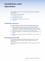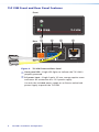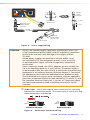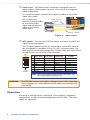
1
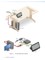
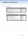
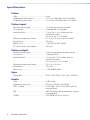
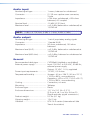
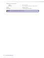
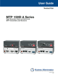
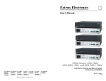
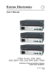
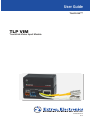
User Guide
TouchLink™
TLP VIM
TouchLink Video Input Module
68-2055-01 Rev. A
03 11
Safety Instructions • English
This symbol is intended to alert the user of important
operating and maintenance (servicing) instructions in the
literature provided with the equipment.
This symbol is intended to alert the user of the presence
of uninsulated dangerous voltage within the product’s
enclosure that may present a risk of electric shock.
Caution
Read Instructions • Read and understand all safety and operating
instructions before using the equipment.
Retain Instructions • The safety instructions should be kept for
future reference.
Follow Warnings • Follow all warnings and instructions marked
on the equipment or in the user information.
Avoid Attachments • Do not use tools or attachments that are
not recommended by the equipment manufacturer because
they may be hazardous.
Consignes de Sécurité • Français
Ce symbole sert à avertir l’utilisateur que la
documentation fournie avec le matériel contient des
instructions importantes concernant l’exploitation et la
maintenance (réparation).
Ce symbole sert à avertir l’utilisateur de la présence dans
le boîtier de l’appareil de  tensions dangereuses non
isolées posant des risques d’électrocution.
Attention
Lire les instructions • Prendre connaissance de toutes les
consignes de sécurité et d’exploitation avant d’utiliser le
matériel.
Conserver les instructions • Ranger les consignes de sécurité afin
de pouvoir les consulter à l’avenir.
Respecter les avertissements • Observer tous les avertissements
et consignes marqués sur le matériel ou présentés dans la
documentation utilisateur.
Eviter les pièces de fixation • Ne pas utiliser de pièces de fixation
ni d’outils non recommandés par le fabricant du matériel car cela
risquerait de poser certains dangers.
Sicherheitsanleitungen • Deutsch
Dieses Symbol soll dem Benutzer in der im Lieferumfang
enthaltenen Dokumentation besonders wichtige
Hinweise zur Bedienung und Wartung (Instandhaltung)
geben.
Dieses Symbol soll den Benutzer darauf aufmerksam
machen, daß im Inneren des Gehäuses dieses Produktes
gefährliche Spannungen, die nicht isoliert sind und die
einen elektrischen Schock verursachen können, herrschen.
Achtung
Lesen der Anleitungen • Bevor Sie das Gerät zum ersten
Mal verwenden, sollten Sie alle Sicherheits-und
Bedienungsanleitungen genau durchlesen und verstehen.
Aufbewahren der Anleitungen • Die Hinweise zur elektrischen
Sicherheit des Produktes sollten Sie aufbewahren, damit Sie im
Bedarfsfall darauf zurückgreifen können.
Befolgen der Warnhinweise • Befolgen Sie alle
Warnhinweise und Anleitungen auf dem Gerät oder in der
Benutzerdokumentation.
Keine Zusatzgeräte • Verwenden Sie keine Werkzeuge oder
Zusatzgeräte, die nicht ausdrücklich vom Hersteller empfohlen
wurden, da diese eine Gefahrenquelle darstellen können.
Instrucciones de seguridad • Español
Este símbolo se utiliza para advertir al usuario sobre
instrucciones importantes de operación y mantenimiento
(o cambio de partes) que se desean destacar en el
contenido de la documentación suministrada con
los equipos.
Este símbolo se utiliza para advertir al usuario sobre
la presencia de elementos con voltaje peligroso sin
protección aislante, que puedan encontrarse dentro
de la caja o alojamiento del producto, y que puedan
representar riesgo de electrocución.
Precaucion
Leer las instrucciones • Leer y analizar todas las instrucciones de
operación y seguridad, antes de usar el equipo.
Conservar las instrucciones • Conservar las instrucciones de
seguridad para futura consulta.
Obedecer las advertencias • Todas las advertencias e instrucciones
marcadas en el equipo o en la documentación del usuario,
deben ser obedecidas.
Evitar el uso de accesorios • No usar herramientas o accesorios
que no sean especificamente recomendados por el fabricante,
ya que podrian implicar riesgos.
Warning
Power sources • This equipment should be operated only from the
power source indicated on the product. This equipment is intended
to be used with a main power system with a grounded (neutral)
conductor. The third (grounding) pin is a safety feature, do not
attempt to bypass or disable it.
Power disconnection • To remove power from the equipment safely,
remove all power cords from the rear of the equipment, or the
desktop power module (if detachable), or from the power source
receptacle (wall plug).
Power cord protection • Power cords should be routed so that they
are not likely to be stepped on or pinched by items placed upon or
against them.
Servicing • Refer all servicing to qualified service personnel. There
are no user-serviceable parts inside. To prevent the risk of shock,
do not attempt to service this equipment yourself because opening
or removing covers may expose you to dangerous voltage or other
hazards.
Slots and openings • If the equipment has slots or holes in the enclosure,
these are provided to prevent overheating of sensitive components
inside. These openings must never be blocked by other objects.
Lithium battery • There is a danger of explosion if battery is
incorrectly replaced. Replace it only with the same or equivalent
type recommended by the manufacturer. Dispose of used batteries
according to the manufacturer’s instructions.
Avertissement
Alimentations• Ne faire fonctionner ce matériel qu’avec la source
d’alimentation indiquée sur l’appareil. Ce matériel doit être utilisé
avec une alimentation principale comportant un fil de terre (neutre).
Le troisième contact (de mise à la terre) constitue un dispositif de
sécurité : n’essayez pas de la contourner ni de la désactiver.
Déconnexion de l’alimentation• Pour mettre le matériel hors tension sans
danger, déconnectez tous les cordons d’alimentation de l’arrière de
l’appareil ou du module d’alimentation de bureau (s’il est amovible) ou
encore de la prise secteur.
Protection du cordon d’alimentation • Acheminer les cordons
d’alimentation de manière à ce que personne ne risque de marcher
dessus et à ce qu’ils ne soient pas écrasés ou pincés par des objets.
Réparation-maintenance • Faire exécuter toutes les interventions de
réparation-maintenance par un technicien qualifié. Aucun des éléments
internes ne peut être réparé par l’utilisateur. Afin d’éviter tout danger
d’électrocution, l’utilisateur ne doit pas essayer de procéder lui-même
à ces opérations car l’ouverture ou le retrait des couvercles risquent de
l’exposer à de hautes tensions et autres dangers.
Fentes et orifices • Si le boîtier de l’appareil comporte des fentes ou des
orifices, ceux-ci servent à empêcher les composants internes sensibles
de surchauffer. Ces ouvertures ne doivent jamais être bloquées par
des objets.
Lithium Batterie • Il a danger d’explosion s’ll y a remplacment incorrect de
la batterie. Remplacer uniquement avec une batterie du meme type ou
d’un ype equivalent recommande par le constructeur. Mettre au reut
les batteries usagees conformement aux instructions du fabricant.
Vorsicht
Stromquellen • Dieses Gerät sollte nur über die auf dem Produkt
angegebene Stromquelle betrieben werden. Dieses Gerät wurde für
eine Verwendung mit einer Hauptstromleitung mit einem geerdeten
(neutralen) Leiter konzipiert. Der dritte Kontakt ist für einen
Erdanschluß, und stellt eine Sicherheitsfunktion dar. Diese sollte nicht
umgangen oder außer Betrieb gesetzt werden.
Stromunterbrechung • Um das Gerät auf sichere Weise vom Netz zu
trennen, sollten Sie alle Netzkabel aus der Rückseite des Gerätes, aus
der externen Stomversorgung (falls dies möglich ist) oder aus der
Wandsteckdose ziehen.
Schutz des Netzkabels • Netzkabel sollten stets so verlegt werden, daß
sie nicht im Weg liegen und niemand darauf treten kann oder Objekte
darauf- oder unmittelbar dagegengestellt werden können.
Wartung • Alle Wartungsmaßnahmen sollten nur von qualifiziertem
Servicepersonal durchgeführt werden. Die internen Komponenten des
Gerätes sind wartungsfrei. Zur Vermeidung eines elektrischen Schocks
versuchen Sie in keinem Fall, dieses Gerät selbst öffnen, da beim
Entfernen der Abdeckungen die Gefahr eines elektrischen Schlags
und/oder andere Gefahren bestehen.
Schlitze und Öffnungen • Wenn das Gerät Schlitze oder Löcher im
Gehäuse aufweist, dienen diese zur Vermeidung einer Überhitzung
der empfindlichen Teile im Inneren. Diese Öffnungen dürfen niemals
von anderen Objekten blockiert werden.
Litium-Batterie • Explosionsgefahr, falls die Batterie nicht richtig ersetzt
wird. Ersetzen Sie verbrauchte Batterien nur durch den gleichen
oder einen vergleichbaren Batterietyp, der auch vom Hersteller
empfohlen wird. Entsorgen Sie verbrauchte Batterien bitte gemäß den
Herstelleranweisungen.
Advertencia
Alimentación eléctrica • Este equipo debe conectarse únicamente a
la fuente/tipo de alimentación eléctrica indicada en el mismo. La
alimentación eléctrica de este equipo debe provenir de un sistema
de distribución general con conductor neutro a tierra. La tercera
pata (puesta a tierra) es una medida de seguridad, no puentearia ni
eliminaria.
Desconexión de alimentación eléctrica • Para desconectar con seguridad
la acometida de alimentación eléctrica al equipo, desenchufar
todos los cables de alimentación en el panel trasero del equipo, o
desenchufar el módulo de alimentación (si fuera independiente), o
desenchufar el cable del receptáculo de la pared.
Protección del cables de alimentación • Los cables de alimentación
eléctrica se deben instalar en lugares donde no sean pisados ni
apretados por objetos que se puedan apoyar sobre ellos.
Reparaciones/mantenimiento • Solicitar siempre los servicios técnicos
de personal calificado. En el interior no hay partes a las que el
usuario deba acceder. Para evitar riesgo de electrocución, no intentar
personalmente la reparación/mantenimiento de este equipo, ya que al
abrir o extraer las tapas puede quedar expuesto a voltajes peligrosos
u otros riesgos.
Ranuras y aberturas • Si el equipo posee ranuras o orificios en su caja/
alojamiento, es para evitar el sobrecalientamiento de componentes
internos sensibles. Estas aberturas nunca se deben obstruir con otros
objetos.
Batería de litio • Existe riesgo de explosión si esta batería se coloca en
la posición incorrecta. Cambiar esta batería únicamente con el mismo
tipo (o su equivalente) recomendado por el fabricante. Desachar las
baterías usadas siguiendo las instrucciones del fabricante.
FCC Class A Notice
This equipment has been tested and found to comply with the limits for a Class A
digital device, pursuant to part 15 of the FCC Rules. Operation is subject to the
following two conditions:
1. This device may not cause harmful interference.
2. This device must accept any interference received, including interference
that may cause undesired operation.
The Class A limits are designed to provide reasonable protection against harmful
interference when the equipment is operated in a commercial environment. This
equipment generates, uses, and can radiate radio frequency energy and, if not
installed and used in accordance with the instruction manual, may cause harmful
interference to radio communications. Operation of this equipment in a residential
area is likely to cause harmful interference, in which case the user will be required
to correct the interference at his own expense.
NOTE: This unit was tested with shielded cables on the peripheral devices.
Shielded cables must be used with the unit to ensure compliance
with FCC emissions limits.
For more information on safety guidelines, regulatory compliances,
EMI/EMF compliance, accessibility, and related topics.
Notational Conventions Used in this Guide
TIP:
A tip provides a suggestion to make setting up or working with
the device easier.
NOTE:
A note draws attention to important information.
CAUTION:
A caution warns of things or actions that might damage
the equipment.
WARNING:
A warning warns of things or actions that might cause
injury, death, or other severe consequences.
Copyright
© 2011 Extron Electronics. All rights reserved.
Trademarks
All trademarks mentioned in this guide are the properties of their respective owners.
iv
TLP VIM • Contents
Introduction
This section gives an overview of the TLP VIM, TouchLink™ Video
Input Module describing its operation and features including
connection and operation with the Extron line of TouchLink panels.
Topics that are covered include:
zz About the TLP VIM
zz Application Diagrams
About the TLP VIM
The TLP VIM is a twisted pair transmitter for composite or S-video
with audio, designed exclusively for use with compatible Extron
TouchLink touchpanels. The TLP VIM has a very specific application
to these touchpanels and is not intended to be used in other
applications.
Compatible TLP touchpanel products have a single video input
supporting AV signals via an MTP receiver built into the touchpanel.
For installations where the video source is within 100 feet of the
touchpanel, the TLP VIP provides a cost effective solution to transmit
video and audio to the touchpanel.
Due to the limited range, the TLP VIM does not require skew or gain
adjustments.
TLP VIM • Introduction
1
Video/Audio
Extron
TLP VIM
POW
ER
+
AUD
IO
+
VID
EO
-
MTP
OUT
PUT
TLP 1000TV
Video/
Audio
PC or DVD
Extron
12 V Power
Supply
PO
Extron
TLP VIM
WER
AU
+
DIO
+
VID
EO
-
MTP
OU
TP
UT
Audio
Video
Video/Audio
(100´ max)
PC or DVD
TLP 1000TV
Figure 1. TLP VIM Application Diagrams
2
TLP VIM • Introduction
Installation and
Operation
This chapter shows how to install and operate the TLP VIM Video
Input Module.
Topics that are covered include:
zz Installation Overview
zz Mounting the TLP VIM
zz TLP VIM Front and Rear Panel Features
zz Operation
Installation Overview
To install and set up the TLP VIM, follow these steps:
1. Turn all equipment off. Make sure the video sources (DSS,
cable boxes, PC, laptop, or other devices), the TLP VIM, and the
touchpanel are turned off and disconnected from power sources.
2. Mount the TLP VIM, see "Mounting the TLP VIM", below.
3. Attach the cables, see "TLP VIM Front and Rear Panel Features" on
page 4.
4. Connect power cords and turn on the devices, see "Operation" on
page 6 .
Mounting the TLP VIM
The TLP VIM includes hook and loop fasteners so that it can be
securely mounted on or under a table or podium near to the
touchpanel.
Shut off all power to connected devices, then mount the TLP VIM as
required.
TLP VIM • Installation and Operation
3
TLP VIM Front and Rear Panel Features
Front
TLP VIM
Rear
a
b
POWER
12V
0.5A MAX
c
d
e
INPUT
VIDEO
AUDIO
OUTPUT
Figure 2. TLP VIM Front and Rear Panel
a Front panel LED – Single LED lights to indicate the TLP VIM is
properly powered.
b DC power input – Single 2-pole, 3.5 mm, orange captive screw
connector for connection of a 12 V power supply.
Use only the included power supply or an Extron authorized
power supply to power the TLP VIM.
4
TLP VIM • Installation and Operation
POWER
12V
0.5A MAX
INPUT
VIDEO
AUDIO
Smooth
Ridges
A
OUTPUT
Captive
Screw
Connector
A
SECTION A–A
Tie Wrap
Power Supply
Output Cord
DC Power Cord
Captive Screw
Connector
3"
16 (5 mm) Max.
Ground
+12 VDC
External
Power Supply
(12 VDC, 1 A )
AC Power Cord
Figure 3. Power Supply Wiring
CAUTION: Always use a power supply supplied or specified by Extron. Use
of an unauthorized power supply voids all regulatory compliance
certification and may cause damage to the supply and the
TLP VIM.
Extron power supplies are certified to UL/CSA 60950‑1 and
are classified as LPS (limited power source). Use of a non‑LPS
or unlisted power supply will void all regulatory compliance
certification.
Unless otherwise stated, the AC/DC adapters are not suitable for
use in air handling spaces or in wall cavities. The power supply is
to be located within the same vicinity as the Extron A/V processing
equipment in an ordinary location, Pollution Degree 2, secured to
the equipment rack within the dedicated closet, podium or desk.
The installation must always be in accordance with the applicable
provisions of National Electrical Code ANSI/NFPA 70, article 75, and
the Canadian Electrical Code, part 1, section 16. The power supply
shall not be permanently fixed to building structure or similar
structure.
c Audio input – One 3-pole captive screw connector for inputting
balanced or unbalanced audio. The audio input is mono only and
either balanced or unbalanced.
Tip
Sleeve
Unbalanced Input
Tip
Ring
Sleeve
Balanced Input
Figure 4. Audio Input Connector Wiring
TLP VIM • Installation and Operation
5
d Video input – Two female BNC connectors on pigtails used to
input either S-video (yellow-chroma, white-luma) or composite
video (white only).
For composite input, connect the composite cable to the white
POWER
video input cable.
12V
For S-video input
connect the luma cable
to the white video
input and the chroma
cable to the yellow
video input.
White: Luma or
Composite
0.5A MAX
Yellow: Chroma
Figure 5. Video Inputs
e MTP output – One female RJ-45 connector to output the MTP A/V
signal to the touchpanel.
The TP cable connecting the TLP VIM output to the MTP input of
the touchpanel is standard UTP or STP Cat 5 or better cable. The
ends may be terminated using either TIA/EIA 568A or TIA/EIA 568B
but both ends must use the same standard.
Pin
T568A
Wire Color
T568B
Wire Color
MTP Signal
Composite
MTP Signal
S-video
1
2
3
4
5
6
7
8
White-green
Green
White-orange
Blue
White-blue
Orange
White-brown
Brown
White-orange
Orange
White-green
Blue
White-blue
Green
White-brown
Brown
Reserved
Reserved
Mono audio+
Video+
Video–
Mono audio–
Reserved
Reserved
Chroma+
Chroma–
Mono audio+
Luma+
Luma–
Mono audio–
Reserved
Reserved
Pins:
12345678
Insert
TP Wires
NOTE: When using Enhanced Skew-Free™ A/V cable, use
the TIA/EIA T568A standard only.
CAUTION: The TLP VIM output uses higher voltages than a LAN. Inputting
those voltages on a LAN communications port may damage the
connection.
Operation
No setup or configuration is required. Once cabling is complete,
apply power to the connected equipment and TLP VIM. The unit is
ready for operation.
6
TLP VIM • Installation and Operation
INPUT
AUDIO
Reference Information
Included Parts
Description
Part Number
TLP VIM
60-1168-01
12 VDC, 1 A power supply
28-071-57LF
3-pole blue 3.5 mm male captive screw connector
10-703-11LF
TLP VIM User Guide
Optional Accessories
Enhanced Skew-Free™ A/V UTP Cable
Part Number
Skew-Free UTP/3, 3 ft (90 cm)
26-569-01
Skew-Free UTP/6, 6 ft (1.8 m)
26-569-02
Skew-Free UTP/12, 12 ft (3.6 m)
26-569-03
Skew-Free UTP/1000, non-plenum, 1000 ft (300 m)
22-141-03
Skew-Free UTP-P/1000, plenum, 1000 ft (300 m)
22-142-03
TLP VIM • References
7
Specifications
Video
Gain����������������������������������������������� Unity
Differential phase error������������������� <1.0° at 3.58 MHz and 4.43 MHz
Differential gain error��������������������� <1.0% at 3.58 MHz and 4.43 MHz
Video input
Number/signal type������������������������ 1 S-video or composite video
Connectors������������������������������������ 2 female BNC on pigtails
Nominal level��������������������������������� 1 Vp-p for Y of S-video and for
composite video
0.3 Vp-p for C of S-video
Minimum/maximum levels�������������� 0.3 V to 1.5 Vp-p with no offset
Impedance������������������������������������� 75 ohms
Return loss������������������������������������� <-30 dB, DC @ 10 MHz
DC offset (max. allowable)������������� 100 mV
Video output
Number/signal type������������������������ 1 set of proprietary analog signals
Connector�������������������������������������� 1 female RJ-45
Nominal level��������������������������������� 1 V p-p for Y of S-video and for
composite video
0.3 V p-p for C of S-video
Minimum/maximum levels�������������� 0.3 V to 1.5 Vp-p
Impedance������������������������������������� 75 ohms
Return loss������������������������������������� <-35 dB @ 5 MHz
Sync
Standards��������������������������������������� NTSC 3.58, NTSC 4.43, PAL, SECAM
Audio
Gain����������������������������������������������� 0 dB (unity)
Frequency response������������������������ 20 Hz to 20 kHz, ±0.25 dB
THD + Noise����������������������������������� 0.03% @ 1 kHz, 0.3% @ 20 kHz at
nominal level
S/N������������������������������������������������� >90 dB, balanced at maximum output
(unweighted)
CMRR�������������������������������������������� >34 dB @ 20 Hz to 20 kHz
8
TLP VIM • References
Audio input
Number/signal type������������������������ 1 mono, balanced or unbalanced
Connector�������������������������������������� (1) 3.5 mm captive screw connector,
3 pole
Impedance������������������������������������� >10k ohms unbalanced, >20k ohms
balanced, AC coupled
Nominal level��������������������������������� -10 dBV (0.32 Vrms)
Maximum level������������������������������� >+2.4 dBu (balanced or unbalanced) at
1%THD+N
NOTE: 0 dBu = 0.775 Vrms, 0 dBV = 1 Vrms, 0 dBV ≈ 2 dBu
Audio output
Number/signal type������������������������ 1 set of proprietary analog signals
Connector�������������������������������������� 1 female RJ-45
Impedance������������������������������������� 50 ohms unbalanced, 100 ohms
balanced
Maximum level (Hi-Z)���������������������� >+3.3 dBu, balanced or unbalanced at
1%THD+N
Maximum level (600 ohm)�������������� >+2.0 dBm, balanced or unbalanced at
1%THD+N
General
Recommended cable type�������������� CAT5/5e/6 (shielded or unshielded)
External power supply�������������������� Input: 100 VAC to 240 VAC, 50-60 Hz,
external power supply
Output: 12 VDC, 1.0 A, regulated
Power input requirements�������������� 12 VDC, 0.5 A max.
Temperature/humidity�������������������� Storage: -40 to +158 °F (-40 to +70 °C)
/ 10% to 90%, noncondensing
Operating: +32 to +122 °F (0 to +50 °C)
/ 10% to 90%, noncondensing
Cooling������������������������������������������ Convection, no vents
Mounting��������������������������������������� Tabletop
Enclosure type�������������������������������� Plastic
Enclosure dimensions��������������������� 1.0" H x 2.4" W x 2.3" D
(2.5 cm H x 6.1 cm W x 5.8 cm D)
(Depth excludes pigtail connectors.)
Product weight������������������������������� 0.2 lbs (0.1 kg)
Shipping weight����������������������������� 1 lb (1 kg)
Vibration���������������������������������������� ISTA 1A in carton (International Safe
Transit Association)
TLP VIM • References
9
Regulatory compliance
Safety�������������������������������������� CE, c-UL, UL
EMI/EMC��������������������������������� CE, C-tick, FCC Class A, ICES, VCCI
MTBF��������������������������������������������� 30,000 hours
Warranty���������������������������������������� 3 years parts and labor
NOTE: All nominal levels are at ±10%.
10
TLP VIM • References
Extron® Warranty
Extron Electronics warrants this product against defects in materials and workmanship
for a period of three years from the date of purchase. In the event of malfunction
during the warranty period attributable directly to faulty workmanship and/or materials,
Extron Electronics will, at its option, repair or replace said products or components, to
whatever extent it shall deem necessary to restore said product to proper operating
condition, provided that it is returned within the warranty period, with proof of
purchase and description of malfunction to:
USA, Canada, South America,
and Central America:
Extron Electronics
1001 East Ball Road
Anaheim, CA 92805
U.S.A.
Japan:
Extron Electronics, Japan
Kyodo Building, 16 Ichibancho
Chiyoda-ku, Tokyo 102-0082
Japan
Europe, Africa, and the
Middle East:
Extron Europe
Hanzeboulevard 10
3825 PH Amersfoort
The Netherlands
China:
Extron China
686 Ronghua Road
Songjiang District
Shanghai 201611
China
Asia:
Extron Asia
135 Joo Seng Road, #04-01
PM Industrial Bldg.
Singapore 368363
Singapore
Middle East:
Extron Middle East
Dubai Airport Free Zone
F12, PO Box 293666
United Arab Emirates, Dubai
This Limited Warranty does not apply if the fault has been caused by misuse, improper
handling care, electrical or mechanical abuse, abnormal operating conditions, or if
modifications were made to the product that were not authorized by Extron.
NOTE:
If a product is defective, please call Extron and ask for an application
engineer to receive an RA (return authorization) number. This will begin
the repair process.
USA:
(714) 491-1500 Asia:65.6383.4400
Europe:31.33.453.4040
Japan:81.3.3511.7655
Units must be returned insured, with shipping charges prepaid. If not insured, you
assume the risk of loss or damage during shipment. Returned units must include the
serial number and a description of the problem, as well as the name of the person to
contact in case there are any questions.
Extron Electronics makes no further warranties either expressed or implied with
respect to the product and its quality, performance, merchantability, or fitness for
any particular use. In no event will Extron Electronics be liable for direct, indirect,
or consequential damages resulting from any defect in this product even if Extron
Electronics has been advised of such damage.
Please note that laws vary from state to state and country to country, and that some
provisions of this warranty may not apply to you.
Extron USA - West
- Headquarters
Extron
USA - East
Extron Europe
Extron Asia
Extron Japan
Extron China
+800.633.9876
Inside USA/Canada
Only
+800.633.9876
Inside USA/Canada Only
+800.3987.6673
Inside Europe Only
+800.7339.8766
Inside Asia Only
+81.3.3511.7655
+81.3.3511.7656 FAX
+400.883.1568
Inside China Only
+1.714.491.1500
+1.714.491.1517 FAX
+1.919.863.1794
+1.919.863.1797 FAX
+31.33.453.4040
+31.33.453.4050 FAX
+65.6383.4400
+65.6383.4664 FAX
+86.21.3760.1568
+86.21.3760.1566 FAX
© 2011 Extron Electronics. All rights reserved. www.extron.com
Extron Middle East
+971.4.2991800
+971.4.2991880 FAX