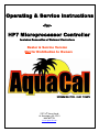
1
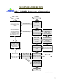
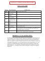
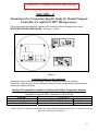
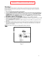
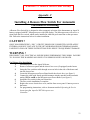
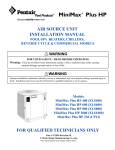
Operating & Service Instructions
-for-
HP7 Microprocessor Controller
Includes Connection of External Controllers
Dealer & Service Version
Not for Distribution to Owners
2737 24th Street North
St. Petersburg, FL 33713
800-786-7751
www.aquacal.com
Revised 10/14/03
TABLE of CONTENTS
GENERAL DESCRIPTION of HP7 CONTROLLER.................................................4
HP7 CONTROLLER SPECIFICATIONS....................................................................4
Inputs: ........................................................................................................................................................4
Outputs:......................................................................................................................................................4
Control Features:.......................................................................................................................................5
CONTROL PANEL LAYOUT .......................................................................................5
SEQUENCE of OPERATION ........................................................................................7
START UP & SETTING OPERATING CONTROLS ................................................8
LEVEL-1 (Owner) ACCESS.......................................................................................................................8
1.
Applying Power to The Controller: ...............................................................................................8
2.
Turning The Heat Pump ON:.........................................................................................................8
3.
Turning The Heat Pump OFF: .......................................................................................................8
4.
Selecting Pool / Spa Thermostat Settings: .....................................................................................8
5.
Changing The Pool Temperature Set Point: ..................................................................................9
6.
Changing The Spa Temperature Set Point:....................................................................................9
7.
Selecting Between °F And °C:.......................................................................................................9
8.
User Lock Code Option [ULC] :....................................................................................................9
9.
Selecting Call / Flex Pump Options [CFO] ….............................................................................10
LEVEL-1 DISPLAY CODES ....................................................................................................................11
[FLO] ...................................................................................................................................................11
[OFF]....................................................................................................................................................11
[CFI].....................................................................................................................................................11
[ULC] ...................................................................................................................................................11
[ELC] ...................................................................................................................................................11
[CFO] ...................................................................................................................................................11
[LOC] ...................................................................................................................................................11
SERVICE & SET UP FEATURES ..............................................................................12
LEVEL-2 ACCESS ...................................................................................................................................12
1. Entering Service Menu:................................................................................................................12
2
2.
3.
4.
5.
6.
7.
Time Delay [dEL] : ......................................................................................................................12
Configuring for External Controllers [JAO] or [FS2]: ................................................................12
Water Sensor calibration [tSC]… ................................................................................................13
Defrost Sensor Calibration [dSC]… ............................................................................................13
Dead Band Differential [dB1] ….................................................................................................14
Changing Service Lock Code & “Backdoor” Entry… ................................................................15
LEVEL-2 DISPLAY SET UP & CALIBRATION CODES .......................................................................16
[LOC] ...................................................................................................................................................16
[dEL] ....................................................................................................................................................16
[JAO]....................................................................................................................................................16
[FS2].....................................................................................................................................................16
[tSC] .....................................................................................................................................................16
[dSC] ....................................................................................................................................................16
[db1] .....................................................................................................................................................16
TROUBLESHOOTING.................................................................................................16
LEVEL-2 FAULT CODES .......................................................................................................................17
[dPO] ....................................................................................................................................................17
[PO] ......................................................................................................................................................17
[dPC] ....................................................................................................................................................17
[PC] ......................................................................................................................................................17
[LP] ......................................................................................................................................................17
[HP] ......................................................................................................................................................17
[FLO] ...................................................................................................................................................17
[FS].......................................................................................................................................................17
[CSE]....................................................................................................................................................17
DEFROST CYCLE OPERATION: .............................................................................17
APPENDIX .....................................................................................................................18
Connecting Specific Jandy Or Pentair/Compool Controllers (See application table within) ................19
Connecting Controllers Not Equipped With an OFF Setting (See application table within)................22
Connecting a Remote Flow Switch ..........................................................................................................23
Installing a Call Flex Kit .........................................................................................................................26
3
GENERAL DESCRIPTION of HP7 CONTROLLER
The HP7 is a powerful microprocessor control designed for use in swimming pool & spa heat
pumps. The control features 3-digit temperature and set point display, with programming changes
easily performed via simple 3-button (key) operation.
The HP7 offers precise water temperature control, accurate defrost management, anti short-cycle
protection, circulator pump management, compressor contactor control, refrigerant circuit
pressure monitoring… all with solid-state reliability. The HP7 monitors water and refrigerant
temperatures using precise thermistor sensors. The control also features full diagnostics messages,
simplifying both installation and service.
Additionally, the HP7 offers maximum corrosion and vibration protection: All printed circuit
board interconnections are soldered, and the main Power Board and Display Board are specially
coated for added protection against humidity, air pollutants, and chlorine vapors.
The HP7 is an excellent alternative to electromechanical controls.
HP7 CONTROLLER SPECIFICATIONS
Inputs:
♦ Swimming Pool Water Temperature Sensor (Thermistor)
♦ Refrigerant Defrost Temperature Sensor (Thermistor)
♦ Low Refrigerant Pressure Switch
♦ High Refrigerant Pressure Switch
♦ Water Pressure / Flow Switch
♦ Remote Flow Switch (Automatic thermostat switching from Pool to Spa)
♦ 3-Position Terminal Block Interface or Alternate “FS2” connection (for connecting full range of
external controllers)
♦ 24 VAC Power Supply (from heat pump)
Outputs:
♦ Compressor Output: Relay 10 amp @ 240 VAC.
♦ Fan Motor Output: Relay 10 amps @ 240 VAC.
♦ Pump Starter: Relay 10 amps @ 240 VAC.
4
Control Features:
♦ Compressor Operation
♦ Refrigerant Circuit Hi & Low-Pressure Lock Out
♦ Water Pump Option (Call Flex)
♦ Precise Evaporator Temperature Control (Defrost Management)
♦ Anti Short Cycle Timer (4-Minute Restart Delay)
♦ Precise Water Temperature Control
♦ Corrosion Protection (Conformal Coating)
CONTROL PANEL LAYOUT
(Appearance will vary between model lines)
1)
2)
3)
4)
5)
6)
7)
8)
9)
DOWN ARROW – Reduces temperature setting. Turn heater off.
SPA INDICATOR LIGHT – Indicates heater is referencing spa thermostat.
POOL / SPA SELECTOR – Selects either pool or spa thermostat.
HEATING INDICATOR LIGHT – Indicates unit is heating.
UP ARROW – Increases temperature setting. ( Maximum pool setting is 95°F (104°F on version 06 or
later boards), maximum spa setting is 104°F)
POOL INDICATOR LIGHT – Indicates heater is referencing pool thermostat.
LED DISPLAY – Displays water temperature when nothing is pressed. Displays desired
temperature when UP ARROW or DOWN ARROW is pressed. Also displays operational, programming,
and fault codes as applicable.
DESIRED TEMP LIGHT – Indicates temperature setting is displayed. Indicates temperature
setting is changing due to the UP ARROW or DOWN ARROW being pressed.
WATER TEMP LIGHT – Indicates water temperature is being displayed.
5
CONTROL PANEL SYMBOLS
UNIT is HEATING
WATER TEMPERATURE SET POINT
ACTUAL WATER TEMPERATURE
POOL SELECTION
SPA SELECTION
6
SEQUENCE of OPERATION
HP-7 (6200P) Sequence of Operation
LINK to Codes
OPERATIONAL CODES
______________________
"FS"...Defrost Mode
Normal Operation in Colder
Weather
FAILURE CODES
______________________
CSE- Control System Error
dPC-Defrost Sensor Shorted
dPO- Defrost Sensor Open
PC- Water Sensor Shorted
PO- Water Sensor Open
LP- Refrigerant Low Pressure
HP5- 5 High Press. Trips < 1Hr
START
Other Possible Displays
PUMP OFF
POWER ON
______________________
"FLO" Displayed
Other Possible Displays
PUMP ON
POWER ON
______________________
Water Temp. Displayed
CALL for HEAT
______________________
Occurs at Set point + Dead
Band Setting...
Fan Starts
HEATER OFF on CODE
(SEE ABOVE)
Heater will Remain Idle Until
Defrost is Satisfied, or Until
Faults are Cleared
5-HPs in 1-Hour
VERSION .07 & UP
_____________________
Controller will Lock Out
Heater if more than 5 HP
Signals are Received in
any 1-Hour period
4-MINUTE TIME DELAY
______________________
Compressor Remains Idle,
while Fan Continues to
Operate
20-Second HP Delay
VERSION .07 & UP
_____________________
High Pressure Signals will
be Ignored for 20-Seconds
COMPRESSOR STARTS
______________________
Compressor & Fan Operate
Until Water Temp. Reaches
Set Point...HEAT LED Lit
SET POINT BELOW 60ºF
______________________
Heater is "OFF"
Pressing Up-Down
Keys Will Display "OFF",
Water Temp. Displayed
SET POINT ABOVE 60ºF
______________________
Heater in Standby, Waiting
Call for heat
Water Temp. Displayed
NOTE
VERSION .04 & BELOW
Fan will continue to operate
indefinitely if water temp.
raises into dead band before
compressor starts.
LINK to Codes
(OR UNTIL FAULT OR DEFROST)
HEATING SATISFIED
______________________
Heater Shuts Off when
Water Set Point Reached
RETURN to TOP of
PAGE
M. Mauro, 10/14/03
M. Mauro, 10/14/03
7
START UP & SETTING OPERATING CONTROLS
LEVEL-1 (Owner) ACCESS
NOTE:
Covered within this section are features and settings typically accessed first by
the installer, and then remaining accessible by the end user (owner). These
features reside at the Level-1 access point within the microprocessor. (Please
see page-11 for information concerning Level-2, service-related access.)
1.
Applying Power to The Controller:
A. When power is first applied, the control performs a lamp test and the display will read
[888]. Following [888], and with versions .04 and greater, the software version will
display briefly. Additionally, all status LED’s lights will illuminate for 4 seconds and
then go off for 1 second.
B. The control will then display the actual temperature as long as the pool-circulating pump
is on.
C. If the pool-circulating pump is off, the control will display the [FLO] (No Water Flow)
code message indicating water is not being circulated though the heat pump.
2.
Turning The Heat Pump ON:
A. Once electrical power is supplied to the heat pump, the pool-circulating pump is
activated, and the control has successfully completed the self-test, the unit is ready to
operate.
B. The control is shipped with the SPA set point in the [OFF] mode and with the POOL set
point selected. The heat pump is automatically switched off if a set point below 60 °F
has been selected. In the [OFF] mode, the control will display the water temperature as
long as the pool water-circulating pump is operational. In the event water is not
circulating through the heat pump, the control will display the [FLO] (No Water Flow)
code message.
C. Using the Up ⇑ arrow key, increase the desired temperature until it exceeds the value of
the actual temperature displayed. (Note: See #8, below, if “000” is displayed upon
pressing up or down arrows.) Once the desired temperature has been entered, the display
will read the actual temperature and the heat pump will start to operate. Both the
compressor and fan must be operating before the “Heat” LED will illuminate.
3.
Turning The Heat Pump OFF:
A. Using the Down ⇓ arrow key, decrease the desired temperature until the display reads
[OFF]. The heater will shut off, and will remain off until the temperature set point is
raised above 60° F.
B. NOTE: Each time the heater is turned off, either manually, or by the thermostat
becoming satisfied, there will be a 4-minute delay prior to restarting.
4.
Selecting Pool / Spa Thermostat Settings:
A. Depress the Pool / Spa key to toggle between the pool and spa temperature set points.
B. The pool / spa led indicator lights located to the left of the temperature display will
confirm the selected temperature set point.
8
5.
Changing The Pool Temperature Set Point:
A. Using the Pool / Spa key, select the POOL temperature set point. The pool set point
indicator light will confirm your selection by lighting.
B. The pool temperature set point range is adjustable from 60°F. to 95° F (104 °F in latest
models). using the Up ⇑ or Down ⇓ arrow keys. The desired temperature can be selected
by briefly depressing the arrow keys, or by holding them down to scroll the temperature
up or down.
6.
Changing The Spa Temperature Set Point:
A. Using the Pool / Spa key, select the SPA temperature set point. The spa set point
indicator light will confirm your selection by lighting.
B. The spa temperature set point range is adjustable from 60°F to 104°F by using the Up ⇑
or Down ⇓ arrow keys. The desired temperature can be selected by briefly depressing
the arrow keys, or by holding them down to scroll the temperature up or down.
7.
Selecting Between °F And °C:
A. Depress both the Up ⇑ and Down ⇓ arrow keys simultaneously until [CF1] (Celsius /
Fahrenheit) code appears.
B. With the [CF1] code displayed, pressing either the Up ⇑ or Down ⇓ arrow key will
display either a (1) or (0). Select (1) for Fahrenheit temperature display or (0) for Celsius
temperature display. Once the desired temperature display has been selected, not
depressing any buttons for 15 seconds will allow the control to save the selection and
return to the normal operating mode. Pressing the Pool / Spa key will also save the
selection and step to the next menu parameter [ULC] (User Lock Code).
8.
User Lock Code Option [ULC] :
This Option Explained:
Heat pumps are shipped from the factory with the ULC option disabled. Enabling the ULC
function permits the heat pump owner to restrict access to the unit controls. With the ULC
option enabled, unless the correct ULC lock code number is entered, changes to Level-1
programming are not possible (I.e.: Altering temperature set points, Pool/Spa selection, C/F
display changes, etc., will not be possible). The ULC option can be thought of as an
electronic lockable cover for the controls.
A. Selecting ULC Option:
1) Depress either of the Up⇑ or Down ⇓ arrow keys; if [000] is displayed, the ULC
feature is already enabled. If [000] displays, proceed to number “6)” of this section;
otherwise, see number “2” below;
2) Depress both the Up ⇑ and Down ⇓ arrow keys simultaneously until the [CF1]
display appears;
3) Depress the pool/spa key once, the [ULC] display will appear;
4) With [ULC] displayed, pressing either the Up or Down arrow key will display either
“1” or “0”. Selecting “0” will allow the control keypad to remain unlocked. Selecting
“1” will enable the User Lock Code option. Then, to enter a lock code number, press
the pool/spa key once. [ELC] (Enter Lock Code) will display;
9
5) With [ELC] displayed, use the Up or Down arrow keys to select a lock code
number. The factory set lock code is “17”. Not depressing any buttons for 15seconds will allow the control to save the selection and return to the normal
operating mode. Pressing the Pool / Spa key will also save the selection and step to
the next menu parameter [CFO] (Call Flex Options);
6) Once the ULC option has been enabled, depressing any key will display [000]
(prompting the entry of the correct lock code number). To gain access to the
controller:
a) Using the Up⇑ arrow, scroll to the correct lock code number, then:
b) Press the Pool/Spa selector button…Current water temperature will be
displayed… Control settings can now be viewed and changed as desired.
c) After a period of approximately four (4) minutes, during which time no
buttons have been pressed, the controller will automatically return to the
locked mode. Provided the ULC selection is “1”, the controller will always
fail-safe in the locked mode.
d) Without knowledge of the correct lock code number, with ULC enabled,
control adjustments will not be possible. Be certain to record your
security code in a safe place. The lock code number may be changed any
number of times by following the instructions detailed above in this section.
B. User Lock Code is Activated, but Pass Number is Not Known (“Back Door Entry”):
NOTE: Should the ULC option be enabled, and a lock code number other than the
factory default (17) be installed but is unknown, the following procedure
may be followed to re-gain controller programming access:
1)
2)
3)
4)
5)
6)
Turn off power to the heater at the breaker;
Simultaneously press and hold down the Up & Down arrows;
Continue holding arrow buttons down while turning the power back on;
Keep holding arrows down for approximately 15 seconds;
[CF1] will appear;
Go to [ELC] by pushing the Pool/Spa button. (Display will change each time P/S
button is pushed.);
7) Go to the up arrow, push it once. (The number that appears is the present, valid lock
code number);
8) It is recommend the access code be returned to the factory default: “17”, before
exiting the program. By going back to [ELC] you can use the Up/Down arrows to
reset the lock code number back up or down to “17”.
9.
Selecting Call / Flex Pump Options [CFO] …
( This feature will apply only if the heater installation includes a Call/Flex module.):
A. Depress both the Up ⇑ and Down ⇓ arrow keys simultaneously until [CF1] display
appears. Depress the pool/spa key twice, the display will appear.
B. With the [CFO] (Call Flex Options) code displayed, use the Up or Down arrow keys to
select, (0) to disable Call Flex Options, (1) to enable the Call Option, or (2) to enable the
Flex Option. Pressing the Pool / Spa key will save the displayed parameter and step to
the menu parameter [LOC] (Service Lock Code).
C. For further instructions, please refer to Call / Flex installation instructions, located in
Appendix at rear of this manual….See item “D”.
10
10. Fan Speed Control… This option is not applicable to any current models. If option present,
factory default setting of “80” MUST remain. Controllers Version .06 or newer will not
contain a FAN option.
LEVEL-1 DISPLAY CODES
Menu Codes
Description
Function
[FLO] No water flow
Displayed Code Message: Appears whenever the circulating
detected
pump is off, or when the heater is not receiving correct
water flow.
[OFF] System is off
Displayed Code Message: Appears whenever system is off,
(With arrow key depressed) and until temperature set point is raised above 60° F.
[CFI]
Celsius Fahrenheit
Programming Entry Point: Allows temperature read-out to
selection
display either Celsius or Fahrenheit.
[ULC] User Lock Code
Programming Entry Point: When activated, steps to the next
menu level [ELC] (enter lock code).
[ELC] Enter Lock Code
Programming Entry Point: Allows end user to select a secret
code so only authorized persons can change heater settings.
[CFO] Call Flex Options
Programming Entry Point: When activated, steps to the next
menu level [CFS] (Call or Flex selection)
[FAN]
Two speed fan control Programming Entry Point: This option is not applicable to
any current model; leave at factory default of “80”.
Service Entry Point: The [LOC] code allows service
[LOC] Entrance to Service
personal the ability to enter a factory code and access
Menu
service adjustable parameters in the software that may
require calibration or adjustments. This menu is available
only to authorized service personnel.
END Level-1 (Owner Accessible) FEATURES
11
WARNING !!!! Dealer & Service Center Use Only
SERVICE & SET UP FEATURES
LEVEL-2 ACCESS
(Includes Configuration for External Controllers)
1. Entering Service Menu:
A. To enter the service menu level, depress and hold both the Up ⇑ and Down ⇓ arrow keys
simultaneously until the code message [CF1] (Celsius Fahrenheit Selection) is
displayed. (NOTE: If [000] displays, User Lock Code is enabled, and the ULC pass
code must be entered before proceeding. See section: “User Lock Code Option [ULC]”,
within Level-1 operating instructions.) Depress the Pool / Spa key four times the [LOC]
code (Entrance To Service Menu) appears.
B. The [LOC] code allows service personal the ability to enter an access code to enter the
service menu. This menu includes the above-mentioned codes that have adjustable
parameters in the software that may require calibration. This section of the Menu is
intended for authorized factory service personnel only.
C. Using the Up ⇑ arrow key, scroll the displayed number to [050].
D. Once the correct service code is displayed pressing the Pool / Spa key will allow access
to the service menu. Note: If access to service menu is denied, see number “7”, below:
“Changing Service Lock Code & “Backdoor” Entry”
E. The first service parameter displayed will be [dEL] (4 minute time delay).
NOTE: Depressing the Pool / Spa key will save the displayed value in any menu
parameter and advance to the next service menu parameters.
2. Time Delay [dEL] :
With the [dEL] (4 minute time delay) code message displayed use the Up ⇑ or Down ⇓
arrow key to select either (1) to allow time delay to remain active or (0) to deactivate the
time delay. Pressing the Pool / Spa key will save the displayed selection and step to the next
service menu parameter [JAO] (Jandy and Compool Controller Interface).
CAUTION !!!: The time delay should only be deactivated for service convenience
and must be reactivated prior to placing the heat pump back in
service. Failure to reset the time delay feature could result in
permanent damage to the heat pump compressor.
3. Configuring for External Controllers [JAO] or [FS2]:
(Also see appendix items “A” & “B”)
3.1: Configuring for External Controllers Equipped with an “OFF” Position [JAO]:
A. Follow the steps 1a. through 1d. above to enter the service menu. Once [dEL] is
displayed, press the Pool / Spa key once to display [JAO].
B. With the [JAO] ( Jandy / Compool Controller Interface) code message displayed,
use the Up ⇑ or Down ⇓ arrow key to select either (0) to disable the Jandy /
Compool Controller Interface, (2) to connect a thermostat type controller (two
wire connection), or (3) to connect a thermostat selector type controller (three
wire connection).
12
WARNING !!!! Dealer & Service Center Use Only
3.2: Configuring for External Controllers not Equipped with an “OFF” Position
Switch, and All Double-Function Air Switch Controllers.
(Also see Appendix Item “B”)
3.3 Remote Flow Switch / Automatic Thermostat Switching [FS2]:
(Also see Appendix Item “C”)
A. Follow the steps 1a. through 1d. above to enter the service menu. Once [dEL] is
displayed, press the Pool / Spa key twice to display [FS2].
B. With the [FS2] (Remote Flow Switch / Automatic Thermostat Switching ) code
message displayed, use the Up ⇑ or Down ⇓ arrow key to select either (0) to
disable Remote Flow Switch / Automatic Thermostat Switching, or (1) enable
Remote Flow Switch / Automatic Thermostat Switching.
C. Refer to the additional instruction, entitled: Installing A Remote Flow Switch For
Automatic Thermostat Switching.
4. Water Sensor calibration [tSC]…
If it is believed the displayed temperature does not match the actual water temperature in the
pool or spa, follow the steps below to verify and adjust the control if necessary. Be certain to
use a reliable thermometer for maximum accuracy:
A. With circulating pump in operation, and water moving through the heater, use a reliable
thermometer to measure the temperature of the pool or spa water. Be sure to measure the
water temperature away from returns. The object is to accurately determine the
temperature of the water entering the heater.
B. Once you have measured the water temperature, compare the result to the heater’s
displayed water temperature. If the temperatures are the same or within 1° F, no
calibration is necessary. If the temperatures differ 2 to 3° F, calibration is necessary…
Follow the instructions below.
C. Follow the steps “1A.” through “1D.” above to enter the service menu. Once [dEL] is
displayed, press the Pool / Spa key three times to display [tSC] (Water Temperature
Calibration). Using either the Up ⇑ or Down ⇓ arrow keys, calibrate the water
temperature sensor by increasing or decreasing the numeric value displayed to match the
water temperature reading measured on your thermometer. The control can be adjusted
to + 10° or - 10° from the nominal displayed temperature. However, offset cal librations
greater than 3° should be avoided…Such large offsets generally indicate problems with
the method of water temperature measurement, a water sensor not properly inserted in
well, or other equipment issues. Do NOT attempt to mask such issues through offset
calibration.
D. Once the corrected temperature is displayed, pressing the Pool / Spa Key will save the
newly displayed water temperature value, and will step to the controller to the next
service menu parameter: [dSC] , Defrost Sensor Calibration.
5. Defrost Sensor Calibration [dSC]…
In the event the Defrost Sensor requires calibration, the following steps must be followed
closely to insure optimal defrost control:
A. Turn the heater off;
13
WARNING !!!! Dealer & Service Center Use Only
B. Remove the unit front panel to gain access to the defrost sensor . The defrost sensor will
be found strapped to the suction line in combination with the TXV sensing bulb, or, in
some models, the defrost sensor will be connected to the suction line independent of the
TXV bulb;
C. Carefully remove the insulation from around the sensor area;
D. Using a highly-accurate, surface-mount thermometer, attach the thermometer probe to
the suction line immediately adjacent to the Defrost Sensor. After the thermometer probe
is securely attached to the suction line, reinstall the insulation foam around the sensor;
E. With foam insulation and unit front panel reinstalled, restart unit, allowing it to run for
10-minutes … Suction line temperature should have stabilized at this point…Note
suction line temperature as measures by the thermometer probe;
F. Follow the steps “1A.” through “1D.” above, to enter the service menu. Once [dEL] is
displayed, press the Pool / Spa key four times to display [dSC] (Defrost Sensor
Calibration). With the service menu parameter [dSC] (Defrost Sensor Calibration)
displayed pressing the Up ⇑ or Down ⇓ arrow key once will display the current
temperature value of the Defrost Sensor.
G. Compare the control’s displayed defrost sensor temperature with the reading on the
thermometer. If the readings are the same, or within 1° F, no calibration is necessary. If
the temperatures differ 2 to 3° F, calibration is necessary. Using the Up ⇑ or Down ⇓
Arrow keys, adjust the display temperature to read the same as the reference
thermometer. The control can be adjusted to + 10° or - 10° from the displayed
temperature. However, offset calibrations greater than 3° should be avoided…Such
large offsets generally indicate problems with the method of suction line temperature
measurement, a defrost sensor not properly attached to the suction line, or other
equipment issues. Do NOT attempt to mask such issues through offset calibration.
H. Once the correct temperature value has been selected pressing the Pool / Spa key will
save the selected temperature and step to the next menu parameter [dB1] (Dead Band
Differential).
6. Dead Band Differential [dB1] …
The dead band differential determines the number of degrees that water temperature must fall
before the thermostat closes again. The dead band is factory set @ .8°. It is highly
recommended the factory default of .8 remain, however, if for some reason the dead band
requires adjustment, follow the steps outlined below:
A. Follow the steps “1A.” through “1D.” above to enter the service menu. Once [dEL] is
displayed, press the Pool / Spa key five times to display [dB1] (Dead Band Differential).
B. With the service menu parameter [dB1] (Dead Band Differential) displayed, pressing the
Up ⇑ or Down ⇓ arrow key will change the dead band differential from 0.2° to 2.0°, in
.2° increments.
C. Once the desired dead band difference is displayed, pressing the Pool / Spa key will save
the currently displayed value and step to the top of the service menu [dEL] (4 Minute
Time Delay).
NOTE: To exit the service menu, not depressing any keys for 15 seconds will
automatically exit the service menu and resume normal operation.
14
WARNING !!!! Dealer & Service Center Use Only
7. Changing Service Lock Code & “Backdoor” Entry…
A. Changing the Code…
The factory default Service Lock Code is “50”. Service personnel are strongly advised
to retain the factory default setting. However, should unauthorized access to the Level-2
(Service) menu be suspected, it may be useful to select a code other than “50”. To
change the Service Lock Code:
1) Enter the service menu level by depressing and holding both the Up ⇑ and Down
⇓ arrow keys simultaneously. Continue to hold keys until the code message:
[CF1] (Celsius Fahrenheit Selection) is displayed;
2) Depress the Pool / Spa key four times… [LOC] (Entrance To Service Menu) will
display;
3) Using the Up ⇑ arrow key, scroll the displayed number to [050] (or the correct,
current code). Note: It may be necessary to double press the arrow key to begin
scrolling;
4) Once the correct service code number is displayed, press the Pool / Spa key to
access the service menu;
5) The first service parameter displayed will be [dEL] (4- minute time delay). Press
the Pool / Spa key six times until the [LOC] (Service Lock Code Entry) is
displayed. By pressing the Pool / Spa key once, the actual, current [LOC] code
will be displayed;
6) At this point, the[LOC] code can be changed from the Factory Setting of [050],
or from whatever the correct setting is, to any number ranging [000] to [999]. It
is recommended, however, unless attempting to prevent tampering, that the
factory setting of: “50” remain in use.
B. “Backdoor” Access (for use when correct Service Lock Code is unknown)…
The following procedure can be used to gain access to the service menu of a unit even
though the current, correct Service Lock Code is unknown. Once access has been
gained, work can be performed within the service menu, and the code may be left as is,
changed back to the factory default setting of: “50”, or the code may be set to any
number ranging [000] to [999]. Unless attempting to prevent tampering, the factory
code setting “50” is recommended:
1) Turn off electrical power to heater …
2) Simultaneously push and hold down both arrow keys;
3) Turn the power back on…
Note:
If, due to physical site restraints or lack of an assistant, the line-voltage electrical
power cannot be turned back on while maintaining the two arrows held down, 24
volt power on the microprocessor board can, instead, be interrupted (by
disconnecting one of the two 24-Volt connections to the controller).
4)
5)
6)
7)
Keep holding down arrows for approximately 20-seconds;
[CF1] will display;
Go to [LOC] by pushing the Pool/Spa button four times;
With [LOC] displaying, push the up arrow one time;
15
WARNING !!!! Dealer & Service Center Use Only
8) [DEL] will display (At this point you have entered the service menu, and servicelevel programming will be possible.);
9) Push Pool/Spa pad until [LOC] appears on readout for the second time;
10) Push the up arrow,…The current, correct lock code will display. Using the up or
down arrow, the code can now be changed back to back to the factory default:
“50”, or the code may be set to any number ranging [000] to [999]. Unless
attempting to prevent tampering, the factory code setting “50” is recommended:
LEVEL-2 DISPLAY SET UP & CALIBRATION CODES
Listed are all service adjustable parameters, paired with the factory default settings and range of
adjustment.
Display
Code
[LOC]
[dEL]
Description
Factory Setting
Range
050
1
0 - 999
0/1
0
0/2/3
0
0/1
[tSC]
Service Lock Code Entry
Anti-Short Cycle 4 min. Time
Delay
Jandy / Compool Controller
Interface
Flow Switch/Automatic
Thermostat Switching
Water Sensor Calibration
[dSC]
Defrost Sensor Calibration
[db1]
Thermostat Dead Band Differential
Factory
Calibrated
Factory
Calibrated
0.8°
+ 10° to -10° of
displayed value
+ 10° to -10° of
displayed value
0.2° to 2.0° of
displayed value
[JAO]
[FS2]
TROUBLESHOOTING
The heat pump microprocessor control in is designed to be self-diagnostic through the use of
various fault codes displayed in the event of a problem. If you believe you are experiencing a
problem with the heater, and need to call for service, it will be beneficial to let the telephone
representative know which code is displayed. This information will allow the service
personal to better understand the problem when responding to the call. Listed on the
following page is list of all fault messages- and what they mean- along with possible causes
and solutions for the error.
16
WARNING !!!! Dealer & Service Center Use Only
LEVEL-2 FAULT CODES
Message Error Description
[dPO] Defrost Sensor Open
Water Temperature
[PO]
Sensor Open
[dPC] Defrost sensor
shorted
Water temperature
[PC]
sensor shorted
Refrigerant system
[LP]
low pressure switch
open
Refrigerant system
[HP]
high pressure switch
open
[FLO] Low or no water
flow detected
Heater in defrost
[FS]
mode
[CSE]
Control system error
Possible Cause
Cut or loose sensor wiring
Cut or loose sensor wiring
Short circuit in defrost sensor wiring or defective sensor.
Short circuit in water sensor wiring or defective sensor.
System refrigerant charge low or defective low-pressure switch.
Low water flow, defective high-pressure switch or wiring.
Circulating pump off, isolation valves set improperly, defective
water pressure switch.
Normal function in lower air temperatures. Fan continues to run
and compressor is off. Compressor will restart when air coil
temperature reaches 38°F or above.
Control may need reset. Disconnect then reconnect power to reset
control if error continues replace control board.
DEFROST CYCLE OPERATION:
The Microprocessor Control monitors the heater’s air-coil temperature, minimizing air-coil
freeze-up during cooler weather conditions. Should the control sense air-coil temperatures
conducive to making ice, the heater’s compressor operation is interrupted while the fan is
allowed to continue in operation. With the compressor off, the air coil begins to warm to the
surrounding air temperature. As air-coil temperatures rise above approximately 38° F, the
compressor is restarted and heating resumes. In the event air temperatures remain below
approximately 38° F, the compressor will remain off until the air temperature rises above
approximately 38° F. Heating of water will not be taking place as long as the compressor
remains off.
17
WARNING !!!! Dealer & Service Center Use Only
APPENDIX
Connecting to, and Configuring Microprocessor for, External Control:
• A: Jandy and Pentair/Compool Brand External Controllers Equipped with an
“OFF” Position
• B: External Controllers NOT Equipped with OFF Setting
• C: Remote Flow Switch Connection
• D: Call/Flex Option
18
WARNING !!!! Dealer & Service Center Use Only
Connecting Specific Jandy Or Pentair/Compool Controllers (See application table within)
Appendix- A
Instructions For Connecting Specific Jandy Or Pentair/Compool
Controllers To AquaCal’s HP7 Microprocessor
The microprocessor terminal block, labeled X,Y,Z, is located on the low-voltage portion of the
MICROPROCESSOR POWER BOARD. (See figure 1, below.)
Figure-1
Controllers Suitable for this Application:
Jandy and Compool controllers have similar features. However, there are two interface
connections. Listed below are the two different interfaces with the corresponding model numbers of
Jandy and Compool controllers.
Interface #1 Compatible Controllers Containing Own Water Temperature Sensors
Controllers Using a 2-Wire Connection to Heat Pump
Jandy
Aqualink
All Aqualink 2, 4, and 8 Series
All Aqualink RS Series
Pentair
Compool
CP3400, CP3600, & CP3800 Series
Intellitouch
All IT Series
Each of the above controllers equipped with own thermostats for heat pump control. Listed below are the
steps to be followed for interface #1.
19
WARNING !!!! Dealer & Service Center Use Only
Warning !
MAKE CERTAIN POWER SUPPLY TO HEATPUMP and CONTROLLER IS DISCONNECTED
PRIOR TO CONTINIUING. FAILURE TO DISCONNECT ELECTRICAL POWER MAY
RESULT IN SERIOUS INJURY OR DEATH.
1. String 18/2 cable from the controller to the heat pump.
2. Locate the MICROPROCESSOR POWER BOARD inside the heat pumps electric box. (See figure 1)
3. Connect the 18/2 cable from the controllers low voltage heater terminals to the MICROPROCESSOR
POWER BOARD Jandy terminal block, terminals Y and Z. (See figure 2)
4. RECONNECT POWER TO THE HEATPUMP.
5. Turn the POOL thermostat to the OFF position by pressing and holding the DOWN arrow key on the
control panel. Then press the POOL/SPA key once to select the SPA thermostat. Turn the SPA
thermostat to the OFF position by pressing and holding the DOWN arrow key on the control panel.
6. Simultaneously, press and hold, both the UP and Down arrow keys until CF1 is displayed.
7. While CF1 is displayed press the POOL/SPA key repeatedly until LOC is displayed. Now press the UP
arrow repeatedly until 050 is displayed.
8. Press the POOL/SPA key repeatedly until JAO is displayed. Press the UP arrow repeatedly until 2 is
displayed.
9. After a delay of approximately 10 seconds, the water temperature is displayed. The controller’s
thermostats are now ready to control the heat pump.
Figure 2
Interface #2 Compatible Controllers-Water Temperature Controlled by Heater
Jandy
AquaSwitch
Compool
CP30
CP100T
The above controllers simply select the heat pump’s POOL or SPA thermostats. Listed below are
the steps to be followed for Interface #2.
20
WARNING !!!! Dealer & Service Center Use Only
Warning !
MAKE CERTAIN POWER SUPPLY TO HEATPUMP and CONTROLLER IS DISCONNECTED PRIOR
TO CONTINIUING. FAILURE TO DISCONNECT ELECTRICAL POWER MAY RESULT IN SERIOUS
INJURY OR DEATH.
1. String 18/3 cable from the controller to the heat pump.
2. Locate the MICROPROCESSOR POWER BOARD inside the heat pumps electric box. (See figure 1)
3. Connect the 18/3 cable from the controllers low voltage heater terminals to the MICROPROCESSOR
POWER BOARD Jandy terminal block, terminals X, Y and Z. The terminals are as follows: X is the
HIGH/SPA terminal, Z is LOW/POOL terminal, and Y is the COM/OFF terminal. (See figure 3 below)
4. RECONNECT POWER TO THE HEATPUMP.
5. Simultaneously, press and hold, both the UP and Down arrow keys until CF1 is displayed.
6. While CF1 is displayed press the POOL/SPA key repeatedly until LOC is displayed. Now press the UP
arrow repeatedly until 050 is displayed.
7. Press the POOL/SPA key repeatedly until JAO is displayed. Press the UP arrow repeatedly until 3 is
displayed.
8. After a delay of approximately 10 seconds, the water temperature is displayed. Set the heat pumps
thermostats to the desired temperature settings. The heat pumps thermostats are now ready to be
selected by the controller.
*NOTE The Compool CP30 uses low voltage pigtails instead of terminals.
Figure 3
21
WARNING !!!! Dealer & Service Center Use Only
Connecting Controllers Not Equipped With an OFF Setting (See application table within)
Appendix- B
HP-7 ….
Interfacing External Controllers
Not Equipped with an OFF Setting
(Including, but not limited to, Double-Function Air Switches)
Compatible Applications
All Intermatic
”Air Force” Series
Controllers
All Air Touch
Controllers
Universal
Controller by
AquaCal
Pentair/Compool:
all “Easy Touch”
Series
WARNING !
DISCONNECT ALL ELECTRICAL POWER WHILE PERFORMING THIS WORK. FAILURE
TO FOLLOW THIS WARNING MAY RESULT IN SERIOUS INJURY OR DEATH.
CAUTION !
ONLY NON-ENERGIZING (“DRY”) CIRCUIT SHOULD BE CONNECTED; NEVER APPLY
EXTERNAL-SOURCE VOLTAGE TO THE HP7 MICROPROCESSOR TERMINAL BOARD.
FAILURE TO FOLLOW THESE INSTRUCTIONS WILL RESULT IN EQUIPMENT DAMAGE.
1.
2.
3.
4.
5.
1.
2.
3.
4.
5.
6.
7.
8.
9.
Connection Instructions (Uses the “FS-2” Connection on HP-7)
Connect two low voltage wires to the common (C) and spa connections (H) of
controller/air switch.
Wires should be cut long enough to reach from controller/air switch to the
heat pump electrical box interface.
Bring wires in to heaters electrical box on the low voltage side.
Interface these wires at power board, FS2 connections. (Female push-on
connectors should be used for wire hookup).
Third wire will not be needed from controller/air switch.
Programming & Activation at Microprocessor
Make sure pool water pump is on.
Power to unit will need to be on.
Hold both up and down arrows simultaneously for five or six seconds (touch
pad will display CF1).
Go to pool/spa switch, toggle until LOC appears.
Go to up arrow, go up to 50.
Go back to pool/spa switch, toggle until FS2 appears.
Go to up arrow, push twice. The number 1 should be displayed.
Step back for until display goes back to water temperature.
Controller is ready to test and use.
Customer and Technical Support
800-786-7751
22
WARNING !!!! Dealer & Service Center Use Only
Connecting a Remote Flow Switch
Appendix- C
Installing A Remote Flow Switch For Automatic
Thermostat Switching
A Remote Flow Switch kit is designed to allow automatic selection of the thermostats on AquaCal
heaters equipped with HP7 Microprocessors with LED display. The Microprocessor will receive a
signal from the flow switch, which can be installed in either the pool return line or the spa return
line. Follow the instructions below for either installation.
CAUTION !
ONLY NON-ENERGIZING (“DRY”) CIRCUIT SHOULD BE CONNECTED; NEVER APPLY
EXTERNAL-SOURCE VOLTAGE TO THE HP7 MICROPROCESSOR TERMINAL BOARD.
FAILURE TO FOLLOW THESE INSTRUCTIONS WILL RESULT IN EQUIPMENT DAMAGE.
WARNING !
DISCONNECT ALL ELECTRICAL POWER WHILE PERFORMING THIS WORK. FAILURE
TO FOLLOW THIS WARNING MAY RESULT IN SERIOUS INJURY OR DEATH.
Pool Return Line Installation
1.
2.
3.
4.
5.
6.
7.
8.
9.
Disconnect power to the AquaCal Heater.
Remove front access panel and the electric box cover (if equipped) on the heater.
String the flow switches cable through an access hole in the side of the heater and
into the electric box.
Locate the Microprocessor Power Board inside the electric box. (see figure 1)
Connect the cable with female quick disconnects already attached to the terminals
marked FS2 A and B on the Microprocessor Power Board. (see figure 1)
Install the flow switch in the pool return line.
The flow switch installation is complete.
Replace the access electric box cover, and the front access panel. Connect power to
the heater.
For programming instructions, refer to document entitled: Operating & Service
Instructions for AquaCal HP7 Microprocessor
Controller.
23
WARNING !!!! Dealer & Service Center Use Only
FLOW SWITCH
INSTALLED IN POOL
RETURN LINE
FIGURE 1
SPA Return Line Installation
1. Disconnect power to the AquaCal Heater.
2. Remove front access panel and the electric box cover (if equipped) on the heater.
3. String the flow switches cable through an access hole in the side of the heater and into
the electric box.
4. Locate the Microprocessor Power Board inside the electric box. (see figure2)
5. Connect the cable with female quick disconnects already attached to the terminals
marked FS2 A and B on the Microprocessor Power Board. (see figure 2)
6. Install the flow switch in the spa return line.
7. Remove the cover from the flow switch. Disconnect the wire from the NC (normally
closed) terminal, and connect to the NO (normally open) terminal. (see figure 2) Replace
the cover on the flow switch.
8. The flow switch installation is complete.
9. Replace the access electric box cover, and the front access panel. Connect power to the
heater.
10. For programming instructions, refer to document entitled: Operating & Service
Instructions for AquaCal HP7 Microprocessor Controller.
24
WARNING !!!! Dealer & Service Center Use Only
FLOW SWITCH
INSTALLED IN SPA
RETURN LINE
FIGURE 2
For Assistance Call AquaCal @ 800-786-7751 Mon. – Fri. 8:00 AM – 5:00 PM
25
WARNING !!!! Dealer & Service Center Use Only
Installing a Call Flex Kit
Appendix- D
Installing a Call Flex Kit
for
Time Clock Management - Heaters Equipped With HP7 Microprocessor
The CALL-FLEX is installed to manage the time clock to the desired heating style of the pool heat
pump owner. With CALL-FLEX, owners select one of three heat modes:
Call Mode
The heater "overrides" the filter pump timer when the pool water drops below the
temperature set point. Two hours after the initial thermostat "call" for heat, the
heater starts. This delay prevents nuisance pool pump cycling.
In CALL MODE, the heater will operate mostly at night when the greatest heat loss
occurs and the heater is least effective. If the owner prefers daytime operation,
the FLEX MODE may be more productive.
Flex Mode
The heater "extends" the heating hours beyond the timer settings. If the heater is
not running when the time clock expires, the pool pump will remain off until the
next timed cycle. If running, it continues the pool and heater operation until the
set point is attained, then stays off until the next timed cycle.
The FLEX MODE is very convenient after cold snaps, if the blanket was left off the
pool, or at initial start-up when the heater must run beyond standard filtering hours to
elevate the pool temperature.
Off Mode
Operation is controlled by the time clock.
26
WARNING !!!! Dealer & Service Center Use Only
Diagrams
27
FIGURE 2
CAUTION !
ONLY NON-ENERGIZING (“DRY”) CIRCUIT SHOULD BE CONNECTED; NEVER APPLY
EXTERNAL-SOURCE VOLTAGE TO THE HP7 MICROPROCESSOR TERMINAL BOARD.
FAILURE TO FOLLOW THESE INSTRUCTIONS WILL RESULT IN EQUIPMENT DAMAGE.
WARNING !
DISCONNECT ALL ELECTRICAL POWER WHILE PERFORMING THIS WORK. FAILURE
TO FOLLOW THIS WARNING MAY RESULT IN SERIOUS INJURY OR DEATH.
INSTALLATION
1. Disconnect power to the AquaCal Heater.
2. Remove front access panel and the electric box cover (if equipped) on the heater.
3. String the CALL FLEX cable through an access hole in the side of the heater and
into the electric box.
4. Locate the Microprocessor Power Board inside the electric box. (see figure 1)
Connect the cable with female quick disconnects already attached to the terminals
marked FLEX A and B on the Microprocessor Power Board. (see figure 1)
5. Mount the CALL FLEX in a convenient location near the heat pump.
6. Make the high voltage connections from the time clock to the Call Flex Contactor
and back to the time clock as shown in Figure 2.
Selecting Call / Flex Pump Options into the Microprocessor:
1. Depress both the Up ⇑ and Down ⇓ arrow keys simultaneously until [CF1] code
appears. Depress the pool/spa key twice, the [CFO] code appears.
2. With the [CFO] (Call Flex Options) code displayed, use the Up ⇑ and Down ⇓ arrow
keys to select, (0) to disable Call Flex Options, (1) to enable the Call Option, or (2)
to enable the Flex Option. Pressing the Pool / Spa key will save the displayed
parameter and step to the menu parameter [LOC] (Service Lock Code).
3.
The CALL FLEX KIT installation is complete.
WARNING !!!! Dealer & Service Center Use Only
28
2737 24th Street North
St. Petersburg, FL 33713
800-786-7751
www.aquacal.com
29