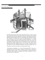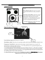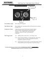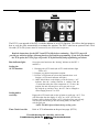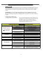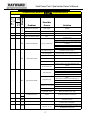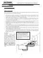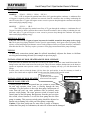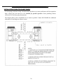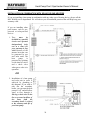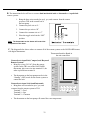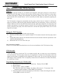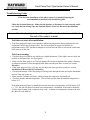
1
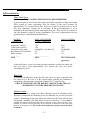
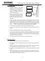
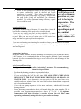
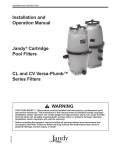
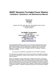
OWNER’S MANUAL
Installation, Operation and Service
HEAT PUMP STYLE
POOL / SPA
HEATERS
TA2267
Jan. 2004
Owner’s
Manual
I.
Operating Principles
•
•
•
II.
Installation Specifications and Procedures
•
•
III.
Receipt inspection of unit……………………………………………………...……10
Determining optimum location…………………………………………………..….10
o Clearance…………………………………………………………….………….11
o Placement………………………………………………………………………..11
o Drainage…………………………………………………………………………11
o Other Precautions………………………………………………………………..12
Application Guidelines and Maintenance
•
•
•
•
•
•
•
•
IV.
How a heat pump works…………...………………………………………………….2
Get familiar with your heat pump ………………………………………………...….3
Temperature control systems for each model……………………….………...……4-9
Climate Conditions……………………………………………………...……….…..12
Pool Cleaning Systems………………………………………………………………12
Efficient Practices
o Using a pool cover…………………………………………..…………………..13
o Water flow………………………………………………………………………13
o Chlorine content…………………………………………………………………13
Cleaning Procedures………………………………………………………..………..14
At the beginning of each season………………………………………….………….14
Occasional / Weekend Use…………………………………………….…………….15
Summertime Shutdown…………………………………………….………………..15
At the end of each season………………………………………...………………….15
Service Procedures
•
•
Before you call for service……………………………………………..………..16, 38
Troubleshooting guide…………………………………………………………...16-18
V.
Warranty……….……………………..……………………………….………...19
VI.
Installation Guide……………………………………………………...…20-40
How a Heat Pump Works
Hayward Heat Pumps take heat from the environment and use it to heat your pool
water. During heat pump operation, liquid freon from inside the unit is pumped
through the system (A) and is turned into a heated gas. This happens when heat is
taken from the surrounding air (B) as it is drawn through the evaporator by the fan.
The compressor (C) receives this warmer gas and compresses it to a higher
pressure, resulting in the freon reaching even higher temperatures. As the unit
sends the heated gas through the heat exchanger, the gas gives up its heat to the
surrounding water (D). The freon reverts to a liquid state as it gives up the heat to
the pool water, which completes the cycle (A). The water (F), which is being
forced through the heat exchanger (D) by your pool pump, is heated by three to
five degrees as it passes through and returned to your pool as heated water. (G)
This process can also be reversed to remove heat from pool water.
A heat pump can transform 4 to 6 units of heat energy (BTU’s) for every 1
equivalent unit of electrical energy it consumes. This results in a coefficient of
performance between 4 and 6. The specific performance coefficient depends on
your heater model, ambient air temperature and climatic conditions, as well as
incoming pool water temperatures.
2
Heat Pump Pool / Spa Heater Owner’s Manual
Get Familiar with Your Heat Pump
Safety Features
Hayward heat pumps are equipped with safeguards that will stop operation to protect your unit in case
of the following events:
• Excessively high refrigerant pressure
• Excessively high water temperature
• Loss of refrigerant
• Fan Motor Failure
• Evaporator Freeze-up
• Low Ambient Temperature
• Refrigerant line blockage or overcharging
High / Low Refrigerant Pressure Switches
•
The high-pressure switch senses the refrigerant pressure in the sealed refrigeration system
and shuts the heater down in the event unsafe operating pressures are reached. The heat pump
will automatically reset after the system pressure drops back to normal operating pressures. When
this switch is tripped, digital displays will read “HP”
•
The low-pressure switch senses the refrigerant pressure in the sealed refrigeration system to
protect against certain conditions that could be detrimental to compressor life. The switch shuts
the unit down in the event of loss of refrigerant, fan motor failure, evaporator freeze-up and
airflow blockage. The switch automatically resets when the pressure rises to normal operating
pressures. The display will show “LP” if this switch is tripped.
Evaporator Freezing
The low-pressure switch will shut the heat pump down when the evaporator starts to freeze.
When the unit starts to freeze the low-pressure switch will be tripped, causing the display to read
“LP” This will prevent the evaporator from becoming damaged or deformed.
Water Pressure Switch
The water pressure switch contacts close when pressure is applied as pool water flows through
the heat exchanger. Low flow rates as well as no flow will let these contacts open and this will
cause the unit to shut down. The display will read “PS” if the water pressure is not sufficient.
Time Delay
All models use a 5-minute time delay to prevent repeated tripping of the compressor thermal
overload, which is caused by attempting startup before system pressures are equalized. Any
interruptions, outside of power loss, will result in a 5-minute time delay.
Low Ambient Temperature
If the air outside the heat pump is not warm enough to produce heat, the system will shut down.
The actual point at which your unit will shut down due to low temperature varies depending on
which model you purchased, current weather conditions, and the amount of sunlight reaching the
heat pump. The shutdown can occur anywhere within a wide range of temperatures, usually
45≡F-55≡F. This is not a “fixed” range. We stress that climate conditions, sunlight, and various
models respond quite differently to low ambient temperature. A shutdown occurs because low
temperatures will activate the systems low-pressure safeguard switch (digital thermostats will
display a code “LP”.) The unit will start up again when the temperature has raised enough to reset
this switch.
Note: Low ambient temperature does not necessarily affect the Chiller models
or the cooling cycle of the heat/cool units.
3
Analog Thermostat
Power Indicator Light: Shows that proper power is
supplied.
Heater Indicator Light: Shows the unit is operating
normally and the thermostat is making a demand for
heat.
Temperature Control Knob: Adjust knob to desired
range, using the diagram on the left as a guide. The
thermostat has a temperature range from 60°F –
105°F(approx. ± 5° at the mid point.) Once you have
the dial is set to the preferred temperature, the unit
will achieve and maintain this temperature.
105°F
Approx.
83°F
Single Mechanical Thermostat
For help with this type of control, refer to the
troubleshooting guide.
60°F
Approx. 83°F
60°F
Power Indicator Light: Shows that power is supplied.
105°F
Heat Indicator Light: Shows the unit is operating normally and the thermostat is making a demand for heat.
Temperature Control Knob: Adjust knob to desired range, using the diagram above as a guide. The
thermostat has a temperature range from 60°F – 105°F. Once the dial is set to a preferred temperature, the
unit will achieve and maintain this temperature.
** The Single Mechanical Thermostat models do not turn off under 60 degrees F. This model was designed
to come on automatically if your water temperature is below 60 degrees to prevent the pool from becoming
excessively cool and creating long recovery times. If your application dictates the need to turn the heater off
for extended periods of time, use the circuit breaker.
For help with this type of control, refer to Troubleshooting Guide for MECHANICAL Thermostat
Control in the back of the owner’s manual.
4
Heat Pump Pool / Spa Heater Owner’s Manual
Dual Mechanical Thermostat
Approx. 83°F
105°F
60°F
Power Indicator Light:
Shows that power is supplied.
Heat Indicator Light:
Shows that the unit is operating normally and the thermostat is making a
demand for heat.
Temperature Control:
Adjust knob pool or spa to desired range, using the diagram
above as a guide. The thermostat has a temperature range
from 60°F – 105°F. Once the dial is set to a preferred
temperature, the unit will achieve and maintain this
temperature.
Mode Toggle Switch:
Off:
Middle position, sets the unit to a “no-heating” mode.
Pool: Flip the switch toward the pool control knob (left). This sets the
unit into pool mode. The unit will maintain the preferred
temperature set point for your pool.
Spa:
Flip the toggle switch toward the spa control knob (right). The unit
will maintain the preferred temperature set point for your spa.
For help with this type of control, refer to Troubleshooting Guide for MECHANICAL
Thermostat Control in the back of the owner’s manual.
5
PST-1
Power Indicator Light:
Heating Indicator Light:
Display:
On/Off:
Indicates that power is
supplied to the heat pump
but does not indicate that
the unit is in operation.
Shows the unit is operating
normally and the thermostat
is making a demand for
heat.
When power is supplied to
the unit, the display will
either show temperature,
diagnostic code (such as “PS”), or rolling dots.
This control does not have a true on/off feature. The unit uses standby mode
instead. Rolling dots in the display indicate standby. Standby mode serves two
functions. (1) It serves as an “off” mode, which keeps the heat pump from
transferring heat into your pool water. (2) Standby allows a pool owner with
remote controlling systems, such as Jandy or ComPool, to maintain pool and
spa temperatures via their remote.
To enter standby mode:
If pool mode is active (indicated by the green led over the pool button), press
the pool button once. Rolling dots should appear on the display.
If spa mode is active (indicated by the green led over the spa button), press the
spa button once. Rolling dots should appear on the display.
To exit standby mode:
Press either the pool or spa mode button.
Mode Selection:
Selecting the desired mode of operation (spa or pool) is accomplished using the
POOL / SPA buttons. A green LED above buttons designates the active mode.
When the pool mode is active, any displays or adjustments apply only to the
pool mode. Adjustments for spa mode must be made while the spa button is
activated. A user can switch between modes without turning the control to
standby first.
Temperature
Setpoint:
Pool mode range is 70-98°F (21-37°C).
Spa mode range is 70-105°F (21- 41°C).
Adjust the setpoint: Continuing to hold the up or down button will scroll the setpoint value until
the desired setpoint is reached. When the desired value has been reached, release the button. The
new setpoint will flash to indicate a new value has been recognized and the display will revert
back to water temperature as indicated by a steady display.
Note: The temperature reading displayed when the unit is in operation (heating indicator light is present)
displays the current water temperature.
To display the setpoint: Press and release the Temperature Set up or down button once will display the current
setpoint for 3 seconds.
For help troubleshooting this type of control, refer to the Troubleshooting
Guide for DIGITAL Thermostat Control in the back of this manual.
6
Heat Pump Pool / Spa Heater Owner’s Manual
PST-4
The PST-4 temperature control is similar to the PST-1
shown above, with two differences. (1) The PST-4 has
a Time Clock Override. (2) The PST-4 has no power
indicator light.
Please read the data for the PST-1 on the previous page before continuing. It will provide you with
descriptions of button functions and setpoint programming.
Time Clock Override:
Notes:
1.An electrician must
wire the TCO
function to your pool
system before it will
work.
2.The 2-hour TCO
checking interval
cannot be adjusted.
This feature must be connected by an electrician. TCO provides a method of
maintaining the pool temperature when a time clock has the pool filter pump
turned off. TCO function then controls the pool filter pump via the PST-4.
TCO will automatically turn the pool filter pump on after 2 hours of “off
time”. It will run the filter pump for 10 minutes while monitoring the water
temperature. If there is more than a 2-degree difference between the setpoint
and the actual pool temperature the heat pump will energize and continue to
run until the setpoint is satisfied.
A user may temporarily override the TCO. An example would be that you
want to use your pool between 9:00 and 10:00 pm. The control may be
programmed to energize the filter pump, which will engage the heat pump to
maintain the pool temperature. This is a temporary measure that can be
initiated in 30-minute increments, for a period up to 3 hours.
Programming for Temporary Pump Override:
1)
2)
3)
4)
Push and hold up and down buttons simultaneously – Display reads P0.0
Release buttons.
Push up button – display reads P0.5 (Each time the up Arrow engages, the
display will increase by .5 increments. Each .5 increment equals 30 minutes,
3 hours is the max.).
Push down button to decrease the temporary override time.
Example of typical TCO cycle: When the time clock turns off the filter pump, a “PS” will show on
the display. A timer starts inside the controller. After 2 hours, the heater will start the filter pump to
circulate water. “PS” is removed from the display and if a demand for more heat is made, the heater
goes back to normal operation. When the water is brought back to temperature, the TCO turns off the
filter pump and the heat pump will shut-down, displaying “PS”. The 2-hour timer is reset and the cycle
will begin anew.
For help troubleshooting this type of control, refer to the Troubleshooting Guide for DIGITAL
Thermostat Control in the back of this manual.
7
PST-5
Heat/Cool
The PST-5 is an upgrade of the PST-4 with the addition of an AUTO function. This allows the heat pump to
heat or cool the water automatically to maintain the setpoint. The PST-5 also has an optional Time Clock
Override (TCO-This feature must be connected by an electrician to operate.)
Read the instructions for the PST-1 and PST-4 fully before continuing. . The PST-1 page will
provide you with descriptions of button functions and setpoint programming. If you have purchased
the TCO option, the PST-4 page will provide TCO functionality and programming procedures.
Run indicator light:
Setting the
AUTO function:
Setting unit to
cool only:
Time Clock Override:
Serves the same function as the “heating” indicator on the PST-1
and PST-4.
1. Disengage the AUTO mode (the AUTO mode indicator light
will be off.)
2. Program your desired temperature setpoint.
3. Press the AUTO button to activate the automatic heat / cool
function. (AUTO mode indicator will light.)
4. “AC5” should show on the display (set at the factory). “AC”
indicates that the cooling function is enabled and the
“5”means that when the water temperature is 5°F above the
setpoint, the unit will energize to cool your pool or spa.
By using the up and down keys, the AC5 can be changed to
values ranging from AC3 to AC9.
Engage the AUTO mode and use the up button to scroll past “AC9”. You
will notice that after the display of “AC9” an “ACP” (AUTO Cool
Primary) will be displayed. When “ACP” is displayed, the unit will only
cool the pool and will not go into the heating mode, no matter how
cool the pool gets.
NOTE: The RUN light will flash during cooling cycles.
Refer to TCO information on the previous page. (PST-4)
If troubleshooting this controller, refer to the
Troubleshooting Guide for DIGITAL Thermostat Control.
8
Heat Pump Pool / Spa Heater Owner’s Manual
Installation Specifications
Receipt Inspection of Unit
Inspect the heat pump pool heater carton upon receipt for possible damage in shipment. Check
the “Tip-n-Tell” indicator attached to the outside of the box. A punctured or oil-soaked area of
the carton could indicate damage to the sealed refrigeration system. If damage has been
incurred or is suspected, bring it to the immediate attention of the delivering carrier. The carton
bears specific warnings stating “DO NOT DROP OR TAILGATE”, as well as arrows indicating
the correct vertical positioning. THE POOL HEATER MUST NOT BE TIPPED OR
TRANSPORTED ON ITS SIDE AS EVAPORATOR “OIL LOGGING” MAY OCCUR.
Upon arrival at the installation site, the unit should be carefully unpacked and again inspection
for any damage that may have occurred in transit. Minor indentations to the aluminum
evaporator fins will not affect performance of the unit.
THE MANUFACTURER CANNOT ACCEPT RESPONSIBILITY FOR
DAMAGE INCURRED OR REPAIRS NECESSITATED DUE TO IMPROPER
HANDLING OF OUR EQUIPMENT.
Determining Optimum Location
THE LOCATION OF THE HEAT PUMP POOL HEATER IS VERY IMPORTANT FOR
EFFICIENT OPERATION.
In order of importance, the installer must consider the following conditions:
o The heat pump will perform more efficiently when placed in direct sunlight.
o Ample air intake
o Avoidance of air recirculation
o Accessibility of service panels
o Means of draining condenser in freezing weather (such as union-style fittings)
o Means of draining condenser and rainwater. Insulation of long water lines (over 25 ft.) from
heater to pool.
The installation of the unit in a fully enclosed area (i.e. garage, shed, etc.) is not
recommended. Consult HAYWARD for indoor pool application analysis.
9
Clearance
A minimum of two feet of clearance from walls, shrubbery, equipment, etc. is required
around the entire pump circumference. This allows for ample air intake. No less than 6
feet clearance above the heat pump is required to prevent re-circulation of air. We
recommend not placing the unit underneath eaves, decks, or porches, as this causes
recirculation of discharged air.
RECIRCULATION OF DISCHARGED AIR BACK INTO THE PUMP WILL
GREATLY REDUCE ITS EFFICIENCY.
6 ft
2 ft
2 ft
Level Placement
The heater should be located on a solid, level surface. The pool heater is
exceptionally quite, but if further noise reduction is desired, the heat pump may be
placed on vibration absorbent pads, which are available from most airconditioning and refrigeration wholesalers.
Drainage
Condensation drain holes are provided in all base pans for adequate removal of
condensation and rainwater. Keep the drain holes unobstructed. Clean them
regularly (with your finger or a short stick) to remove any debris that may block
them.
HEAT PUMPS GENERATE WATER CONDENSATION DURING
NORMAL OPERATION. THIS SHOULD NOT BE MISTAKEN FOR A
LEAK IN THE UNIT.
The troubleshooting section provides recommendations should you suspect a leak.
10
Heat Pump Pool / Spa Heater Owner’s Manual
Other Precautions
The heat pump should not be placed near sprinkler systems, especially those
where fertilizer is added. This is very corrosive and, over time, will severely
damage the unit. If you live in an oceanfront area, the heat pump should be placed
out of direct spray of sand and salt. This will also clog, damage, and corrode the
unit. You may consider protecting your heat pump by planting shrubbery or a
privacy fence between the unit and the prevailing beachfront wind.
Application Guidelines and Maintenance
Climate
Weather conditions have a significant impact on pool heating. Local weather and
climate data are general conditions surrounding your pool. The microclimate
surrounding the pool must also be considered.
Lots of shade, low air temperature, relative humidity, and high wind velocity at the
pool surface negatively impact pool heating and will require an increased pool
heater output to maintain pool temperature.
Cleaning Systems
Some pools have cleaning systems attached to the filter pump intake (i.e. crawlers
and skimmers). These devices slow the flow of water entering the heat pump. As
low flow rates may damage the heat pump, built-in safeguards will automatically
shutdown the unit in instances of low water flow.
Dirty pool filters slow water flow and may cause a shutdown.
Familiarize yourself with the pool filter. Know how to check and clean or replace
it yourself. Do not completely trust a pool cleaning service to do this task for you.
11
Efficient Practices
Using A Pool Cover
POOL COVERS ARE STRONGLY RECOMMENDED.
A pool loses heat in several ways but testing shows that evaporative cooling (the cooling
effect created by water evaporating from the surface of the pool) accounts for
approximately 75% of a pool’s heat loss. However, if a pool is covered when it is not in
use, most evaporative cooling can be prevented. If the pool temperature is to be
maintained, the pool heating system must replace heat lost. Thus, the use of a pool cover
can offer dramatic savings in energy consumption. The cover’s approximate effect on
pool heat losses is illustrated in the table below:
SOURCE
Of Heat Loss
Evaporative cooling
Convection loss to air
Ground loss (dry earth)
Re-radiation to environment
Make-up water
__________
Total
POOL UNCOVERED
(USED 12 HRS/DAY)
POOL COVERED
75%
15%
(Negligible – less than 1%)
9%
1%
________________
100%
30%
10%
(Negligible)
9%
1%
________________
50% of uncovered
pool losses
As the table shows, a pool cover that prevents evaporative cooling can reduce the
heat loss from a pool approximately 50% (which also cuts your power
consumption by 50%.)
Water Flow
To minimize heating times, make sure all water valves are open completely, that
the water level of the pool is at the correct height, and that any fountains or
waterfalls are disconnected or turned off. Maintain 30–75 gpm flow rate.
CHECK YOUR PUMP FILTER WEEKLY. REPLACE OR CLEAN AS
NECESSARY TO ENSURE PROPER FLOW RATES.
Chlorine Content
Chlorine is corrosive, along with other chemicals used in sanitizing pools.
Improperly maintained pH alkalinity levels are unhealthy for you and your pool
systems. Maintaining proper water pH levels will increase the life of all your pool
components, including your heat pump. Automatic chlorinators, if used, must be
installed downstream of the heat pump (in the return line to the pool) and a check valve
installed in a manner that will not allow the raw chlorine to drain back to the heat pump
when the water pump is off. Do not allow pool maintenance people to pour chemicals
in skimmer.
12
Heat Pump Pool / Spa Heater Owner’s Manual
Cleaning Procedures
•
Disconnect power to the unit
(usually at the circuit breaker in
your house). Verify that power is
off by checking the display for
lights. If no lights are present,
proceed to the next step.
Fan Guard
Acorn Nut
Fan Motor
Mount Nut
•
Remove the fan guard by removing
(4) acorn nuts that retain the fan
guard. DO NOT REMOVE THE
NUTS THAT RETAIN THE FAN
MOTOR.
•
Using a water hose and spray nozzle, direct water through the evaporator coil fins
to flush out debris. Spray from inside the unit to push debris out. Never spray
from the outside, as this will lodge debris in the evaporator coil fins. Keep nozzle
back 12-18 inches from the evaporator coil surface to prevent deforming the fin
surface. NOTE: Do not aim a water stream directly at the fan motor.
•
Use a rag to remove build-up from the fan blades and the fan motor.
•
If necessary, use a shop-vac to remove debris from the base pan and other areas of
the unit.
•
Replace the fan guard and acorn nuts, securing them tightly.
•
Use a rag and soapy water to clean the external plastic panels of the unit. DO
NOT wipe across the evaporator coil fins, as this will deform them and affect
operational efficiency. Instead use a very soft-bristle brush to gently loosen grit
and grime that may have collected.
•
Reconnect power to the unit and ensure it is operating correctly.
Beginning of season
•
Perform the cleaning procedures recommended above.
•
Be certain the water lines and the heat pump are reconnected and / or drain valves
are closed.
•
With the pool heater power off, start the pool filter pump. Check for possible
water leaks and be certain there is adequate water flow: 30 – 75 GPM.
•
Complete your normal preparation and / or cleaning of the pool for the start of the
season.
•
Turn the heat pump power on and set the thermostat to the desired temperature.
TIP: Setting the thermostat to its highest setting will not heat the water any faster
than setting the desired temperature point.
13
•
Allow the heat pump pool heater and the pool filter pump
to operate continuously until the desired pool water
temperature is reached. This is best accomplished by
removing the pool pump timer cogs (stops). This prevents
the pump from cycling off and allows for continuous
operation. To achieve optimum heating efficiency, a pool
cover should be used.
Occasional Pool Use
Heat pumps are NOT fast pool heaters. You must allow at least 48
hours before swimming for the pool to be noticeably heated.
If you are only using your pool on the weekends, it is more
economical to turn the heat pump down a few degrees and cover
the pool. When you are ready to swim again, it will require less
energy and time to regain a preferred temperature.
It will take several
days of continuous
operation for your
pool to heat up to
temperature. The
exact length of
time will vary
depending on pool
size, ambient
temperature, wind
speed, and use of a
cover.
If you are not planning on swimming for a month or longer, you may choose to turn the
heat pump off. In this instance, it is recommended that the heat pump be drained of pool
water and bypassed.
Summertime Shutdown
During the summer months, when the heat pump is not needed, you can shut the unit off.
In this instance, it is recommended that the heat pump be drained of pool water and
bypassed. It is also recommended leaving the cover off as well to take advantage of solar
warming effects.
End of season (Winterizing)
Many pool service companies offer “winterizing” assistance. We recommend using
them for this procedure.
• Perform the cleaning procedures recommended above.
• Disconnect the power supply (usually at the circuit breaker in your house).
• If you are closing the pool for the winter, BE ABSOLUTELY CERTAIN TO
DISCONNECT THE HEAT PUMP FROM THE UNIONS AND DRAIN ALL
WATER LINES. As an alternative, you may prefer to fill the water lines with a
suitable antifreeze solution. Note: the water lines are best drained when compressed
air is forced through them.
• Cover the heat pump to protect it from snow and water, which could freeze and
damage the unit.
• Some heat pump owners desire their pool heated during the winter months. This is
possible when daytime temperatures are above 50° F (10° C). If nighttime
temperatures fall below freezing be certain to keep the pool filter pump
operating continuously during this time to prevent freeze damage.
14
Heat Pump Pool / Spa Heater Owner’s Manual
Service Procedures
Before You Call For Service
If there appears to be a problem, refer to the troubleshooting guide on the following
pages. There is an additional troubleshooting chart available at the end of the installation
manual containing information for troubleshooting your heat pump.
1. Make sure that the swimming pool filtration system is turned on.
2. Is the main power (circuit breaker) on?
3. Is the "Power" indicator light illuminated?
4. Is the heat pump thermostat set at a high enough level to enable the system to turn on? Adjust the
thermostat to a higher setting.
5. Check the outside temperature. HAYWARD heat pumps will not turn on when the outside air
temperatures drop near 45 degrees.
6. Make sure that the pump and skimmer baskets are free of debris. Also ensure that the pool filter is clean
and supplying proper water flow to the heat pump.
7. The heat pump is not able to maintain your desired temperature? Depending on the time of the year, you
may need to adjust your pool filtration systems hours of operation (increase run time).
Note: Use a solar blanket/cover on the surface in order to keep a higher level of heat retention.
Heat Pumps with Electronic Displays
1. If diagnostic code "PS" is illuminated, this indicates improper water flow. Ensure that pool filter pump
basket, skimmer basket, and filter are free of debris and clean.
2. If diagnostic code “LP” is illuminated, this indicates that the outside air temperature is too low. When
this occurs the Heat Pump shuts itself off automatically. When the outside air temperature rises enough the
heat pump will automatically turn on.
3. If diagnostic code "HP" is illuminated, this indicates that a low water flow condition may exist. Check to
see that the pool pump basket, skimmer basket and pool filter is clean. After checking these items, if the
"HP" indicator is still illuminated contact HAYWARD for service.
15
Troubleshooting
Check the installation of the heat pump first to assure it is installed per the installation manual. Ensure the
electrical hook-up is correct by checking the breaker is sized correctly for your unit and the wiring is per
the National Electric Code. Reference the installation manual to ensure that the plumbing is installed
correctly.
Circuit Breakers: if you suspect that a circuit breaker may be tripped, turn the breaker to the “off”
position and then back to “on”. Visually checking the breaker is “on” is inadequate, as some switches
move only a short distance when they trip. Toggle the switch to “off” then “on” every time you suspect it
is tripped.
Troubleshooting a Chiller model
or cooling cycles of a heat/cool unit:
If you are troubleshooting problems with a Chiller model or
cooling cycles of a heat/cool unit, the following charts cover
the majority of issues. If you are unable to resolve or
determine a problem, additional info can be obtained by
contacting the HAYWARD Service Dept.
Troubleshooting Guide for MECHANICAL Thermostat Control
Problem
Possible Cause
Possible Solution(s)
Heat pump is not running
No power to unit
Breaker is thrown
Thermostat not turned up high enough
5 minute delay timer still running
Make sure power is on.
Check the breaker / see note above
Turn thermostat up until unit comes on
Be sure the 5 minute delay has passed
Make sure filter is clean
Make sure filter pump is on
(Note: the pool filter pump
must be running before the
Low water flow
heat pump will operate.)
Outside temperature to low
Heat pump running
but not heating
“Heat” or “RUN” does not come on.
Fan not functioning
Make sure thermostat is high enough
System Component failure.
Thermostat set too high
Heat pump runs continually
Electrical component failure
Bad valve or improper water flow
Heat pump is cycling
(on / off too quickly)
Low refrigerant, low ambient temp,
or high humidity with low ambient temp
Condensation
Water coming from bottom of unit
Unhook cleaning devices (skimmers, crawlers, etc.)
Check outside ambient temperature / wait for warmer
temperatures for unit to operate. (refer to Operating Principles)
Call HAYWARD for service info.
Adjust thermostat for higher heating temperatures.
Refer to page 7 to find your thermostat instructions.
Call HAYWARD for service info.
Turn thermostat down
Turn off the filter pump. If the unit is still running after 2 minutes,
turn off the power to the unit and contact HAYWARD for service.
Check valve settings and ensure water flow is sufficient
(is the filter pump running continually?) If heat pump continues
to cycle, turn unit off to prevent compressor damage.
Check evaporator coil for severe frost. Turn unit off to prevent
compressor damage.
If heat pump continues to cycle, turn unit off to prevent
compressor damage.
This is normal and there is no reason to be concerned
Turn the unit off for at least 2 hours, but leave the filter pump
running continuously. If water dries up then it is only
condensation. Otherwise there is a possible leak.
Possible water leak
16
Heat Pump Pool / Spa Heater Owner’s Manual
Troubleshooting Guide for DIGITAL Thermostat Control
(blank)
Display
Heat
(green)
Run
(green)
PST-1 & PST-4
only
Power (red)
Lights
•
•
No power to heat pump
High / Low Pressure Switch
PS
LP
Water Pressure Switch
Low Pressure Switch
Solution
Tripped circuit breaker/ no Check breaker and insure that the unit is properly
power supply
installed.
Faulty electrical component
•
•
•
Problem
Possible
Cause
Call HAYWARD service department for info.
Call HAYWARD service department for info.
Check ambient temperature, if lower than 50 F,
Unit will not run
Check water flow to heat pump. .
Clean your filter
. Make sure all valves are open and bypass valve
Low or no water flow
is closed.
Ensure pool filter pump is on
Normal operation for TCO function
Turn off fountains, crawlers, etc.
Outside temperature too
Check ambient temperature. Wait for warmer
cold. (Refer to page 7.)
temperature (refer to page 7.)
Outside temperature too
cold.
Loss of refrigerant
Call HAYWARD service department for info.
Switch failure
Call HAYWARD service department for info.
Fan motor failure
Call HAYWARD service department for info.
Coil obstruction
Call HAYWARD service department for info.
Air flow obstruction
Perform cleaning procedures described in this
manual.
Call HAYWARD service department for info.
Low water flow
•
HP
High water temp
High Pressure Switch
Refrigerant is overcharged
•
SF
120
•
888
•
C=1
•
RHD
Temperature sensor
Thermostat reset
Check water flow to heat pump. .
Clean your filter
. Make sure all valves are open
Ensure pool filter pump is on
Set unit to “ACP” if you have the heat / cool
option.
Refer to text on PST-5 control board.(pg 12)
Check pool temp. Wait until pool needs heat.
Call HAYWARD service department for info.
Have a professional adjust to proper levels
Contact HAYWARD for service info.
Switch Failure
Contact HAYWARD for service info.
2-speed filter pump
Make sure speed is set to “high”
Failure
Contact HAYWARD for service info.
Temporary display. Shows for 1-2 secs when the
unit is first turned on.
Temporary display. Appears intermittently. Ignore
Internal board identification
unless it does not disappear.
Refer to owner’s manual of the remote device.
Remote device is
If you do not have a remote device connected, call
controlling the unit.
HAYWARD for service info.
Normal operation
17
MANUFACTURER'S LIMITED WARRANTY
HEAT PUMP POOL HEATERS
Energy Utilization Systems, Inc. (HAYWARD) warrants to the original installed location, the
HAYWARD heat pump pool heater to be free of defects in materials and workmanship for a period of
five years. The compressor part has a limited ten-year warranty, a pro rata basis for years 6-10. This
warranty covers the cost of parts and labor for five years and starts from the date of purchase or within
six months of date of manufacture, whichever is first. HAYWARD will not void this warranty due to
improper pool water chemistry. This warranty is valid only if the product is installed according to the
HAYWARD specifications. This warranty is valid only for products sold for use within the state of
Florida. Products sold for use outside the state of Florida have a warranty of five years for all parts and
one year for labor. Warranty outside of Florida does not include refrigerant or other expendable
materials. Note: Lil’ HotSpot, HotSpot, and SunSpot units have 5-year parts warranty and 1-year labor
warranty everywhere.
This warranty does not include services such as inspection, maintenance, or unnecessary service calls
due to erroneous operational reports, external valve position, or electrical service. It also does not
include the repair or damage due to negligence, accident, or other conditions beyond the normal
intended use of the unit. This warranty is void if the product is repaired or altered in any way by any
persons or agencies other than those authorized by HAYWARD, and is in lieu of all other warranties,
expressed or implied, written or oral. There are no implied warranties of merchantability or fitness for a
particular purpose that apply to this product. This warranty applies only within the continental USA. For
warranty outside the continental USA, contact HAYWARD.
At its option, HAYWARD will replace or repair any HAYWARD part that proves defective if such
parts are returned to our factory, freight collect, within the warranty period. It is agreed that such
replacement or repair is the exclusive remedy available from HAYWARD. Unless authorized by
HAYWARD and performed by a factory authorized service center, HAYWARD is not liable for any
labor involved in the removal of defective parts or the installation of replacement parts. HAYWARD is
not liable for damages of any sort whatsoever, including incidental and consequential damages. Parts
returned and services performed under terms of this warranty must be approved by HAYWARD. All
parts returned under terms of this warranty will be repaired or replaced and returned transportation
charges prepaid, by best and most economical means.
This warranty applies to units shipped after July 1,2002.
18
Heat Pump Pool / Spa Heater Owner’s Manual
Installation
Guide
Receipt Inspection of Unit………………………………………………………10
Determining Optimum Location……………………………………………….10
•
Refer to Section II in the Owners’ Manual………………………10-12
Electrical Connections…………………………………………….…………….21
•
Model Specifications………………………………………………...21
•
Wiring Recommendations…………………………………………...22
•
Wiring Diagrams…………………………………………………23-25
Plumbing Specifications………………………………………………….……..26
•
Typical Installation Layout………………………………...……..27
•
Flow Rate…………………………………………………………28
•
External By-pass………………………………………………….28
•
Unions…………………………………………………………….28
Installation of Pool Heater Above Pool Surface……………………….………28
Installation of Pool Heater Below Pool Surface…………………….…………28
Installation of Multiple Heat Pumps……………………………………….…..29
Installation in Combination with Solar or Gas Heaters…………………..…..30
Initial Start-Up…………………………………………………………………..31
Connecting to Remote Systems………………………………………..……32-33
Connecting the TCO…………………………………………………………34-35
Trouble Shooting Guide……………………………………………………..36-37
• Refer to Section IV of the owners manual……………………17-18
Obtaining Service……………………………………………………………16, 38
19
Electrical Connections
All units are equipped with an electrical wiring schematic inside the electrical panel. If one is not
provided, please contact the factory at 1-800-432-8387 to obtain one.
Warning!
Disengage main power disconnect before attempting
installation.
Power connections supplied to the unit must be in accordance with
national and local electric code.
• Use an approved flexible conduit to supply power to the heat pump where appropriate to code.
• Electrical Grounding must be supplied congruent to national and local code.
• If the unit is installed within 15 feet of the pool, the National Electric Code requires the use of Ground
Fault Interrupter (GFI) circuit protection on all installations regardless of their location.
• An outdoor waterproof disconnect should be mounted adjacent to the heat pump for service safety.
• Refer to charts below for electrical ratings / recommendations:
Model /
Type
Volts
Hz
Phase
Compressor
Nom. Amps
Compressor
LRA
HP-4
HP-5
Model /
Type
Operating Specs
230
60
1
19.9A
115A
Operating Specs
Volts
Hz
Phase
Compressor
Nom. Amps
Compressor
LRA
Fan Motor
RLA
Fan Motor
HP
Minimum
Circuit
Ampacity
230
60
1
19.9A
115A
1.7A
Fan Motor RLA
1.7A
Fan Motor HP
¼
Minimum Circuit
Ampacity
30
Max Fuse
30A
Max Fuse
30A
Volts
Hz
Phase
Compressor
Nom. Amps
Compressor
LRA
230
60
1
Volts
Hz
Phase
Compressor
Nom. Amps
Compressor
LRA
Fan Motor
RLA
Fan Motor
HP
Minimum
Circuit
Ampacity
230
60
1
PE-42
27.9A
129A
Fan Motor RLA
2.9A
Fan Motor HP
½
Minimum Circuit
Ampacity
40
Max Fuse
50A
PE-52
Max Fuse
20
¼
30
27.9A
129A
3.3A
½
40
50A
Heat Pump Pool / Spa Heater Owner’s Manual
Wiring Recommendations
Min Wire
Ga.
Min. Wire
Ga. For
runs over
50 ft.
Wire alloy
FuseHACR or
Time
Delayed
Power
consumption
–Watts
HP4**
HP5**
PE42**
PE52**
10
8
10
8
10
6
10
6
Copper
Copper
Copper
30
50
30
50
3450
5800
3450
5800
Copper
Note:
It is not necessary to remove the entire front panel to make
electrical connections. Doing so can damage sensitive electronic
controls and can void the warranty.
DO NOT TOUCH OR ALLOW LOOSE WIRES TO TOUCH THE
THERMOSTAT CIRCUIT BOARDS DURING INSTALLATION.
21
This wiring diagram
is for use with all
units that have
digital thermostats.
It is also for use with
units that have the
optional TCO.
FA N
M O TO R
BRO W N
Y ELLO W
R ED
B LA C K
R ED
O RAN GE
TH E R M O S TA T
A M B ER
LIG H T
P R ES S U R E
S W ITC H
O RAN GE
T2
T1
B LU E
TIM E D ELA Y
R ELA Y
C O N TA C TO R
B LA C K
This wiring diagram
is for Lil’ HotSpot
units only.
(N O )
(5 M IN )
L2
L1
B LU E
(N C )
LP
Y ELLO W
R ED
LIG H T
HP
B LA C K
(N C )
B LA C K
B LU E
R ED
R ED
C
BRO W N
F
C
H
R
B
B LA C K
LIN E LIN E
C A P A C ITO R
C O M P R ES S O R
G R O U N D LU G
TA -2 4 4 0
22
Heat Pump Pool / Spa Heater Owner’s Manual
This wiring diagram
is for use with all
units that have
mechanical single
thermostats.
This wiring
diagram is for
use with H/C
units.
23
This wiring
diagram is
for use with
all units that
have
mechanical
dual
thermostats.
24
Heat Pump Pool / Spa Heater Owner’s Manual
Plumbing Specifications
Typical Installation Layout
PIPING CONNECTIONS
Note: A detachable connection (union) must be utilized immediately adjacent the heater to facilitate servicing
and winterizing the unit. (See example on next page)
•
The heat pump pool heater is designed for easy piping connections into the pool water filtering system.
The pool heater condenser (heat exchanger) is provided with 1 ½” female fittings which are easily
adapted to rigid poly vinyl chloride (PVC) or flexible plastic tubing.
• Use 2” PVC Schedule 40 piping and 2” fittings and components for building the piping system.
Components under this size will impede water flow rates and hinder the efficiency of the unit. Utilize a 2”
- 1 ½” reducer to enter the heat pump.
• Pipefittings such as reducers, tees, and elbows cause pressure to drop as water flows through them. Plan
the plumbing layout carefully, using as few fittings as possible to connect your heat pump.
• PIPING TO THE POOL HEATER MUST BE IN ACCORDANCE WITH APPLICABLE STATE AND
LOCAL CODES.
• It is important that the pool heater be connected downstream from the pool pump and filter in the return
line to the pool. Connect the pipe from the filter outlet to the fitting near the bottom of the pool heater
marked "COLD WATER IN FROM PUMP"
• THE WATER TO BE HEATED MUST ENTER THE BOTTOM OF THE HEAT EXCHANGER TO
AVOID THERMOSTAT "SHORT-CYCLING".
• Connect the fitting near the top of the pool heater marked "HOT WATER OUT TO POOL" to the return
piping to the pool. Long runs of piping to and from pool (over 25 feet) should be insulated to prevent
heat loss to ground or air.
NOTE: When the piping installation
CAUTION:
is complete, operate the pool filter
Automatic
erosion
type
pump with the heat pump off. Check
chlorinators, if used, must be
the entire piping system for leaks.
installed downstream (between
Observe the filter water pressure gauge
the heat pump and the pool) of the
for abnormalities or obstructions in the
heat pump and a check valve (or
filtering system.
Hartford Loop) installed in a
manner that will not allow the raw
chlorine to drain back to the heat
pump when the water pump is off.
Do not allow pool maintenance
people to pour chemicals in
Damage to your
skimmer.
system and the heat pump could
result.
25
26
Heat Pump Pool / Spa Heater Owner’s Manual
FLOWRATE
MODELS:
PE 42** / PE22** / HP-4* / PE 32**
The 3 ¼ HP is designed for nominal water flow of 45 gpm through the condenser. A minimum flow
of 20 gpm is required to insure sufficient heat removal from the condenser, thus avoiding overheating the
unit. Flow rates above 75 gpm will begin to create excessive pressure drop through the condenser and require
unnecessarily high pumping energy.
MODELS:
PE 52** / HP-5*
The 5 HP is designed for nominal water flow of 55 gpm through the condenser. A minimum flow of
30 gpm is required to insure sufficient heat removal from the condenser, thus avoiding overheating the unit.
Flow rates above 75 gpm will begin to create excessive pressure drop through the condenser and require
unnecessarily high pumping energy.
EXTERNAL BYPASS
If the flow rate exceeds 75 gpm, a bypass loop must be installed around the heat pump (refer to page
20). The bypass loop piping should be sized to provide approximately 40-60 gpm to the heat pump. Pump
capacity versus backpressure performance curves for the pump used in the pool system should be consulted to
determine the flow rate. This may require a pressure or flow gauge measurement at the pump discharge.
UNIONS
A detachable connection (union) must be utilized immediately adjacent the heater to facilitate
servicing and winterizing the unit. (See example on previous page)
INSTALLATION OF POOL HEATER ABOVE POOL SURFACE
If the pool heater is installed more than three feet above the surface of the pool water install directional flow
fittings on the end of the return water line to the pool. This will create adequate backpressure at the heater to
operate an important water pressure switch. A pool supply company can help you with directional flow
fittings.
In some cases, such as when the heater 6-8 feet above the pool surface, it may be necessary to install a
positive flow switch such as AQUALARM™ in the water line instead of the pressure switch.
INSTALLATION OF POOL HEATER
Adjustment Knobup decreases pressure setpoint
down increases the setpoint
BELOW POOL SURFACE
A water pressure switch is integrated into our systems to ensure that
the unit only operates when water is flowing through the heat
exchanger. If a pool surface is above the heat pump, backpressure of
water from the pool can cause problems with an internal water
pressure switch setting. The water pressure switch is located in the
control panel of the heat pump. Backpressure from the pool can close
this switch, whose function is to tell the heat pump that the filter
pump is running. This pressure switch setting should be adjusted so
that the unit is running only while pool filter pump is operating.
Caution: If the heat pump runs for more than a couple of minutes
without the filter pump in combination, the unit will overheat and be damaged.
27
Water Pressure Switch
INSTALLATION OF MULTIPLE HEAT PUMPS
If a heat pump pool heater sizing calculation indicates that two or more pool heaters will be required to
heat a single pool, the units are to be installed for parallel operation. Series plumbing reduces
efficiencies of each heat pump downstream.
The diagram below shows installation of two units in parallel. Contact HAYWARD for additional
information if installing more than two units.
28
Heat Pump Pool / Spa Heater Owner’s Manual
INSTALLATION IN COMBINATION WITH SOLAR OR GAS HEATERS
If you are installing a heat pump in combination with any other type of heating device, please call the
HAYWARD service department. We will advise you of installation practices that will help keep your
warranty valid.
If you are installing other
pool heaters, such as gaspowered or solar-powered
devices:
1. They
must
be
installed in a parallel
circuit and operated
independently (only
one at a time) for
your warranty to stay
valid. Because of the
intense heat that can
be generated by gas
and solar units, the
heat
pump
is
protected by isolating
it with shut-off valves
and a check valve
when gas or solar is in
operation.
OR
2. Installation of a heat pump
and solar unit in series is
achieved by plumbing to
this diagram. If you wish to
only run the secondary
heater, you can turn the heat
pump to “off” and still allow
water to flow through it.
Placing a check valve in the
line to prevent backflow of
hot
water
from
the
secondary heater is critical
to the warranty and life of
your heat pump.
29
INITIAL START-UP - (Electronic Control Systems Only)
After completing the electrical and piping connections to the pool heater, follow the procedures
outlined below to insure that the pool heater is functioning properly.
Before proceeding, MAKE CERTAIN there are no air or water leaks in any plumbing connections
or piping and water flow is within the proper flow rate ranges:
MODEL PE 42:
MODEL PE 52:
20 gpm min. – 70 gpm max.
30 gpm min. – 75 gpm max.
NOTE: Damage caused by flow rates outside this range will void your warranty.
1.Check to see that pool heater thermostat is in the "OFF" or “Standby” position.
2.Apply power to the pool heater by plugging in the fused disconnect block or moving the circuit
breaker to the “ON” position.
3.With the pool filter pump operating, set the pool heater thermostat to the desired temperature.
4. When the pool heater starts, disconnect power to the pool filter pump. The pool heater should
instantly cease operation. IF THE POOL HEATER CONTINUES TO OPERATE, THE
WATER PRESSURE SWITCH MUST BE ADJUSTED (see page 30). If the pool heater ceases
operation when power to the filter pump is disconnected, the water pressure switch adjustment is
correct for this installation.
5. Restore power to the pool filter pump. There is a five (5) minute time delay period that will
prevent the heat pump from restarting. Wait for a few minutes for the heat pump to restart. If the
restart doesn’t occur, refer to the troubleshooting section.
6. When the unit starts, visually check the fan is operating and air is being discharged upward from
the unit. Listen for the sound of the compressor starting. If you are not familiar with, or are unsure of
exactly what sound the compressor makes, take an amp reading around one incoming power wire
near the contactor. The amp reading should be 20 amps or above when the compressor is running
(even at low ambient and/or water temperature.)
7. If both the fan and compressor are operating, allow the pool heater to operate for 10 - 15 minutes
in order for system pressures to stabilize.
8. Using a thermometer, check to see if the discharge air is 5°F - 128F cooler than the ambient air
temperature. If discharge air does not have a noticeable temperature change, refer to troubleshooting
section.
30
Heat Pump Pool / Spa Heater Owner’s Manual
Connecting to Remote Systems
Most HAYWARD heat pumps are compatible with one or more of the remote systems in the pool
and spa industry. The single mechanical thermostat units are compatible with the Jandy AquaLink,
Compool, and Hayward remote systems, but are not compatible with the Intermatic or Jandy
AquaSwitch remote systems. The dual mechanical thermostat units and all of the digital thermostat
units are compatible with all known remote systems in the industry. Note: HotSpot and Lil’ HotSpot
models require special connections. The HAYWARD engineering staff can advise you on methods
of connecting remotely.
Examples of connecting with three popular remote systems are listed below. Thoroughly read the
installation instructions of the remote system before connecting to your heat pump.
A. The diagram below shows how to connect HAYWARD single/dual mechanical and all digital
thermostats to the Jandy AquaLink:
Note: on units with
optional cooling modes, the
Aqualink controls only
heating cycles.
31
B. The instructions below tell how to connect dual mechanical units to Intermatic or AquaSwitch
remote systems:
1. Bring the three wires marked as pool, spa, and common from the remote
system to TB2 in the control box of
the heat pump.
2. Connect the pool wire to “L’
3. Connect the spa wire to “H”
4. Connect the common wire to “C”
5. Place the toggle switch in the “OFF”
position
Note: The thermostats on the heater still control the
temperature of the water.
C. The diagram below shows where to connect all of the remote systems to the HAYWARD heaters
with digital thermostats.
Thermostat Interface Board in
the unit control box
Connection to AquaLink, Compool, and Hayward
Remote Systems:
• Bring two wires (24 VAC) from the remote
system. In the TB1 area of the HAYWARD
thermostat, place one wire into terminal 11, the
other is placed into terminal 4.
•
The thermostat on the heat pump must be in the
“Standby” (OFF) mode for the remote system to
control the unit.
Connection to Aqua Switch and Intermatic:
• Bring three wires marked as pool, spa, and
common from the remote system to TB1:
Terminal 7 = Pool
Terminal 9 = Spa
Terminal 2 = Common
•
The thermostat on the heat pump will control the water temperature.
32
Heat Pump Pool / Spa Heater Owner’s Manual
Time Clock Override (TCO) Function
Purpose:
This function provides another way to maintain pool temperature. Most pool systems use a time clock to
control the pool’s filter pump. The time clock may have the filter pump off for several hours at a time. Since
the filter pump must be flowing water through the heat pump for heating of the water to occur, the Time
Clock Override (TCO) function allows a user to control the pool filter pump by temporarily bypassing the
time clock.
The TCO function is designed to automatically turn the pump on after 2 hours of “off-time”. It will run the
pump for 10 minutes while the heat pump thermostat monitors the pool temperature. If there is more than a
2-degree difference between the thermostat setpoint and the actual pool temperature, the heat pump will
energize and continue to run until the setpoint is satisfied. The TCO will then disengage and allow the time
clock to control the filter pump. If the time clock doesn’t start the filter pump within 2 hours, the TCO will
begin this cycle again.
Wiring the TCO Function:
1)
2)
3)
4)
Refer to the wiring diagrams located on the next page.
Wire the pool filter pump power in parallel using the TCO contactor located in the heat pump control
box.
Wiring shall comply with the 1996 National Electrical Code and all state and local requirements of the
Authority Having Jurisdiction.
Maximum Load: 25 FLA at Volts: 240,1 ph.
Note to electrician / installer:
Use the TCO override feature described below to test for correct installation of the TCO function wiring.
TCO Override:
A user may temporarily override the TCO. An example would be that you want to use your pool between
9:00 and 10:00 pm. The heat pump control may be programmed to energize the filter pump, which will
engage the heat pump to maintain the pool temperature. In other words, you can force the heat pump and
filter pump to work on demand. This is a temporary measure that can be initiated in 30-minute increments,
for a period up to 3 hours.
Programming Instructions for TCO Override:
1. Push and hold up and down buttons simultaneously – Display will read “P0.0”
2. Release buttons.
3. Push up button – display reads P0.5
Note: Each time the up Arrow engages, the display will increase in “.5” increments. Each
increment equals 30 minutes, 3 hours (P3.0) is the maximum.
4. Push down button to decrease the temporary override time. Continue decreasing the time until
reaching P0.0 to turn the override off.
33
R E C O M M E N D E D W IR IN G F O R T IM E C LO C K O V E R R ID E N O TE: TH E
T C O
C O N TA C TO R
IS R A TED
FO R 25A
M A X IM U M
LO A D .
A W S M O D E LS
C A U T IO N !!!
TH IS M O D EL IS
D ES IG N ED FO R
M O R E TH A N O N E
PO W ER S O U R C E.
D IS C O N N EC T A LL
PO W ER B EFO R E
S ER V IC IN G .
C A PA C ITO R
H eat Pum p
C ontactor
T C O
C ontactor
A W S C O N TR O L B O X
D isconnect
A W S C O N TR O L
BO X D O O R
N O TE: TH IS D IA G R A M
IN TEN D ED FO R TC O H O O K U P
O N LY. R EFER TO N O R M A L
W IR E D IA G R A M FO R M O R E
IN FO R M A TIO N .
Filter Pum p
Tim e C lock
R E C O M M E N D E D W IR IN G F O R T IM E C LO C K O V E R R ID E - E U
S M O D E LS
EU S C O N TR O L B O X
C A PA C ITO R
H eat Pum p
C ontactor
D W G # : TA -2312
D W G B Y: JM R
C A U T IO N !!!
TH IS M O D EL IS
D ES IG N ED FO R
M O R E TH A N O N E
PO W ER S O U R C E.
D IS C O N N EC T A LL
PO W ER B EFO R E
S ER V IC IN G .
N O TE: TH IS D IA G R A M
IN TEN D ED FO R TC O H O O K U P
O N LY. R EFER TO N O R M A L
W IR E D IA G R A M FO R M O R E
IN FO R M A TIO N .
D isconnect
T C O
C ontactor
N O TE:
TH E T C O
C O N TA C TO R
IS R A TED
FO R 25A
M A X IM U M
LO A D .
Filter Pum p
Tim e C lock
D W G # : TA -231 4
D W G B Y: JM R
34
Heat Pump Pool / Spa Heater Owner’s Manual
Troubleshooting Guide
First check the installation of the unit to assure it is installed following the
recommendations detailed in the installation guide.
Check the electrical hook-up. Make sure the breaker or disconnect is sized correctly and is
on. Verify that the wiring is per the National Electric Code (see Electrical Specifications
section.)
A second troubleshooting chart containing additional information is available at
the end of the owner’s manual.
Unit does not start after installation:
• If the heat pump pool heater was exposed to subfreezing temperature during shipment, the lowtemperature switch may be deactivated. The unit must then be exposed to ambient air
temperatures above 48°F and direct sunlight for several hours in order to activate the switch and
allow start-up of the unit.
•
•
•
•
•
•
Unit is not running:
Check for the power light or any display on a digital thermostat. If the light is not on, check the
breaker or disconnect box. Are fuses good?
Make sure the filter pump is on. The heat pump will not operate until the filter pump is flowing
an adequate amount of water through the unit. Make sure the pool filter is clean (see section
Flowrate.)
If the water pressure is low, you may need to adjust the water pressure switch (see section
Installation of Heater Below Pool Surface)
Check the thermostat. If the filter pump is flowing water through the unit, turn up the thermostat
and see if the unit comes on.
Make sure the 5-minute time delay, which protects the compressor, has timed-out.
Check the outside ambient temperature. Unit will not operate when the ambient temperature is
below 45° F
If the heat pump pool heater is installed in an area where the air temperature will fall below 44°F
(+/- 3°F), the unit will shut off at these lower temperatures. In addition, if the relative humidity
is high, some frosting of the evaporator may occur. As higher air temperatures return to the area,
the unit will come back on.
35
Unit is running but not heating:
• Is the fan turning?
• Is the air coming out of the top cooler than ambient air temperature?
• Check the thermostat. Make sure it is turned up high enough.
If the heat pump does not appear to be heating because it is not detectable to the touch,
remember the difference at any given flow rate may be only a degree or two. A quick and simple
way to see if the unit is actually heating, is to check the air temperature (ambient air) being
drawn into the unit and compare it to the air being blown out of the top. If the air coming in is
70° F and the air coming out is 65° F, there is a 5° F difference – which is going into the water.
If the two temperatures are the same, there may be a problem and you should contact the
manufacturer.
Unit runs continuously:
• First, turn off the thermostat. If the unit turns off, the thermostat was set too high.
• Second, if the unit is still running after you turn off the thermostat, turn off the filter pump. If
the unit is still running after approximately 2 minutes, disconnect power. The main contactor
may have failed or the water switch may have failed.
• To check to the water pressure switch, make sure that power is disconnected from the heat pump.
Turn on the filter pump and check across the wire terminals of the water pressure switch with an
Ohmmeter. If the ohmmeter indicates an open circuit, try adjusting the knob on the switch. If it
“closes”, leave the knob at this setting and re-check the heat pump operation.
Unit is cycling:
• Is the water flow rate within acceptable ranges? (See section Flowrate.) Check the filters and
the valves to ensure they are clean and fully open. The water pressure switch may have to be
adjusted (see section Installation of Heater Below Pool Surface.)
• Check the evaporator coil for severe frost.
• If the unit continues to cycle, turn power off to the heat pump to keep the cycling from effecting
the compressor.
Unit is noisy:
• If the heat pump seems noisy at start-up and then returns to normal sound levels, this is not cause
for concern. Such noise may occur when the unit has been off for a longer-than-normal period of
time.
36
Heat Pump Pool / Spa Heater Owner’s Manual
OBTAINING SERVICE ASSISTANCE
Before You Call For Service
If there appears to be a problem, refer to the installation troubleshooting guide above. There is an
additional troubleshooting chart available at the end of the owner’s manual containing
information for troubleshooting your heat pump.
1. Make sure that the swimming pool filtration system is turned on.
2. Is the main power (circuit breaker) on?
3. Is the "Power" indicator light illuminated?
4. Is the Heat Pump Thermostat set at a high enough level to enable the system to turn on? Adjust the
thermostat to a higher setting.
5. Check the outside temperature. HAYWARD Heat Pumps will not turn on when the outside air temperatures drop
near 45 degrees.
6. Make sure that the pump and skimmer baskets are free off debris. Also ensure that the pool filter is
clean and supplying proper water flow to the Heat Pump.
7. The heat pump is not able to maintain your desired temperature? Depending on the time of the year, you may need
to adjust your pool filtration systems hours of operation (increase run time).
Note: Use a solar blanket/cover on the surface in order to keep a higher level of heat retention.
Heat Pumps with Electronic Displays
1. If diagnostic code "PS" is illuminated, this indicates improper water flow. Ensure that pool filter pump basket,
skimmer basket, and filter are free of debris and clean.
2. If diagnostic code “LP” is illuminated, this indicates that the outside air temperature is too low. When this occurs
the Heat Pump shuts itself off automatically. When the outside air temperature rises enough the heat pump will
automatically turn on.
3. If diagnostic code "HP" is illuminated, this indicates that a low water flow condition may exist. Check to see that
the pool pump basket, skimmer basket and pool filter is clean. After checking these items, if the "HP" indicator is
still illuminated contact HAYWARD for service.
Service Information
Hayward Pool Products
1-800-432-8387
Hayward Pool Products
1 Hayward Industrial Drive
Clemmons, NC 27012
37
Notes:
38
Heat Pump Pool / Spa Heater Owner’s Manual
Notes:
39
Notes:
40
Heat Pump Pool / Spa Heater Owner’s Manual
Warranty Card
1. Fill out the reverse side of this card.
2. Cut card along the edges and drop it in the mail to us.
CUT
ALONG
EDGES
Hayward Pool Products
1 Hayward Industrial Drive
Clemmons, NC 27012
ATTN: HEAT PUMP WARRANTY DEPT.
41
Celcius
0
1
2
3
4
5
6
7
8
9
10
11
12
13
14
15
16
17
18
19
20
21
22
is
Fahrenheit
32
34
36
37
39
41
43
45
46
48
50
52
54
55
57
59
61
63
64
66
68
70
72
Celcius
23
24
25
26
27
28
29
30
31
32
33
34
35
36
37
38
39
40
41
42
43
44
45
42
is
Fahrenheit
73
75
77
79
81
82
84
86
88
90
91
93
95
97
99
100
102
104
106
108
109
111
113