1
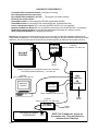
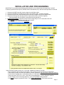
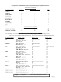
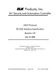
PRODUCT APPLICATION NOTES
M1 Audio Control
Basic control of distributed audio
Systems using the M1 Control
COMPATIBLE AUDIO DISTRIBUTION CONTROLLERS
Russound - CAM & CAV series only (RNET)
Proficient - M4 & M6 (MZC series) Requires the Proficient Command Interface.
Nuvo - Grand Concerto and Essentia series.
NOTE: The extent of integration such as the number and type of commands supported varies by audio
partner. Not all systems share or support all the same commands. Only 1 brand of audio equipment may
be connected to a single M1 installation. Brands may not be combined or intermixed.
FIRMWARE / SOFTWARE REQUIREMENTS
Ness-M1G Automation/Security Control with firmware 5.1.24 or later
Ness-M1XEP Ethernet Adapter with firmware 1.3.10 or later.
Elk-IP232 IP to Serial Adapter with firmware 1.0.16 or later
ElkRP2 Remote Programming Software (version 2.04)
* Firmware “Flash” upgrade files may be downloaded from the Ness M1 Dealer site http://www.ness.com.au/M1Downloads.asp
IMPORTANT NOTICE:
The ELK-IP232 Bridge does not support encryption nor secure network
connections. If remote (Internet) connections are allowed to it, whatever serial
device is connected will be vulnerable. It is recommended that the Bridge be
used within a local network only, behind a router and/or firewall.
Page 2
OVERVIEW
Effective with M1 Control firmware 5.1.24 and later it is now possible to control specific brands/models (see page 2)
of distributed audio systems using the M1. The primary communications medium is TCP-IP (LAN “Network”),
whick requires the use of a Ness-M1XEP “Ethernet Port Interface”, and a Elk-IP232 “IP to Serial Adapter”. The IP232
connects to the serial port of the audio controller. In addition, some audio controllers require an additional piece of
hardware to accomodate a RS232 communications connection. The M1 Control, M1XEP, and IP232 will need to
have the most recent firmware (see page 2), and may require flash updating. This application document is intended
to assist with installation and operation of the M1 equipment. It is beyond the scope of this document to assist
with setup of the audio equipment. The audio equipment should be completely setup and functional, and the
Installer should be familiar with it’s setup and operation PRIOR to connection of the M1 equipment. For questions
about the audio equipment please consult the audio manufacturer or the manual supplied with that equipment.
HOW M1 AUDIO COMMANDS FUNCTION
M1 Audio commands can originate from a M1 Automation Rule (“Then” command) or from a PC or M1 Touchscreen
running RM Remote Management software. The M1XEP receives commands and traffics them to/from the audio
equipment. The M1XEP contains detailed information about the audio brand/model, the zone and source names,
and the IP address for connecting with the IP232. Setup for all this information is done from ElkRP2 Programming
Software, under a new tab on the M1XEP Setup screen. Two new command types “CD” and “CA”, were added to
http://www.ness.com.au/downloadcenter.asp
for use by the
the M1 ASCII serial protocol
M1XEP. The M1XEP converts the ASCII commands into the appropriate native protocol of the audio controller.
PLEASE NOTE: There are no menus or buttons on an M1 Keypad that can support direct audio commands.
However, it is possible to use other actions from a keypad (function keys, arm, disarm, etc.) to fire a task or trip
an automation rule which can in turn send an audio command.
M1 AUTOMATION RULES
The three portions of an M1 Automation Rule are: Whenever, And, Then. The “Whenever” defines an action or event
used as a trigger. The “Then” defines the action e.g. audio command to be executed or transmitted. The “And”
defines a conditional e.g filter that might either allow or disallow a command based on a specific condition being
true or not true. In other words, if a rule contains “And” statements they ALL must be true in order for the
succeeding “Then” command(s) to execute. Below is a rule example which turns the audio Zone 1 On if the alarm
system is disarmed withing a certain time period.
WHENEVER alarm system becomes disarmed
AND the time of day is earlier than 11:00pm
AND the time is later than than 8:00am
THEN turn audio zone 1 ON
Audio commands are only available from “Then” elements. The M1 does not monitor or concern itself with the state
or present condition of an attached audio controller, therefore it is not possible for a rule to be triggered or filtered on
the audio state or condition. Commands are one way, going from the M1 to the audio controller. Some commands
are acknowledged by the audio controller, and may result in a response or display by the RMS Remote software,
or by a higher level 3rd party software. However, the M1 ignores the acknowledgements.
Source equipment attached to the audio controller may or may not be controllable from the M1 Automation Rules.
The level of integration with source equipment varies by the particular brand/model of the audio equipment. Audio
systems that maintain extensive knowledge of their attached sources do not necessarily share this through their
“third party” RS232 serial ports, even though it may be viewable on their attached system keypads, etc.
As previously mentioned, all audio commands are communicated through the Ness-M1XEP Ethernet Interface across
the LAN to an Elk-IP232 module. Setup involves programming the M1XEP will the IP address and Port number for
the IP232 module, followed by a setting of which audio partner is to be connected. After this the Source and Zone
names need to entered so that data will all become populated into the rules statements.
Page 3
HARDWARE REQUIREMENTS
Compatible Audio Distribution System. [See page 2 for listing]
Ness-M1G Automation/Security Control.
}
Ness-M1XEP Ethernet Adapter. (101-215)
} See page 2 for firmware versions]
Elk-IP232 IP to Serial Adapter.
}
Serial Ribbon Cable for connecting M1G to M1XEP (supplied with M1XEP)
Serial Ribbon Cable for connecting IP232 to Audio Equipment (supplied with IP232)
Cat 5 or Cat6 Network Cables (2) for connecting M1XEP & IP232 to LAN (not supplied)
Network LAN Switch or Router with two (2) available connections for the M1XEP & IP232. (not supplied)
ElkRP2 Programming Software for programming the NessM1G [See page 2 for software version]
IP232 Config Utility Software for configuring the ElkIP232
IMPORTANT: Carefully plan for the IP Addresses you intend to use. We recommend the M1XEP and IP232 both be
assigned Static IP Addresses. These must comply with the LAN settings so they do not interfere with any other static
addresses, and do not intefere with the allocated range of DHCP (dynamic) IP Addresses the network is serving.
Serial
Port 0
Ness-M1XEP
ELK-M1XEP
ETHERNET
ETHERNET
INTERFACE
INTERFACE
9 Pin
RS232
Example:
Static IP Address: 192.168.0.251
Ness-M1G
ELK-M1G
CONTROL
CONTROL
Power
12VDC
Sample examples for IP addresses based on the customers
LAN utilizing Network Addressing: 192.168.0.xxx
Example:
PC IP Address: 192.168.0.10
Networked
Computer
LAN
SWITCH
OR
ROUTER
M1-TS071
Touchscreen
Example:
Static IP Address: 192.168.0.253
Power
12VDC
Example:
Static IP Address: 192.168.0.252
ELK-IP232
ELK-IP232
IP TO
SERIAL
IP TO SERIAL
DISTRIBUTED AUDIO
DISTRIBUTED AUDIO
CONTROLLER
CONTROLLER
Page 4
9 Pin
RS232
Power
12VDC
NOTE: The IP Addresses shown are
an example only. They must be set to
conform to the LAN setup.
INSTALLATION AND PROGRAMMING
IMPORTANT! Be certain that the Distributed Audio System is fully configured and working locally. DO NOT
connect any external devices (IP232, M1XEP, Audio Control Module, etc.) until local audio operation is confirmed.
1.
2.
3.
4.
Connect the M1XEP to the M1 Control using 9 pin serial ribbon cable.
Connect the M1XEP to the LAN using a Cat5 or Cat6 network cable. (customer supplied).
Connect the Elk-IP232 to the Distributed Audio controller or adapter using a serial ribbon cable.
Connect the IP232 to the LAN using a Cat5 or Cat6 network cable. (customer supplied).
Verify the M1XEP, the LAN Switch, and the IP232 are all powered up.
5. Configuring the IP232. Install & launch the IP232 Config Utility on a PC connected to the LAN.
- Click Search to find the IP232 connected to the network.
- Highlight the IP232 found and click Configure.
- Verify the IP232 Firmware version is 1.0.16 or later. Update the firmware if it is older.
- Enter a descriptive Device Name for the IP232. This is useful for future identification on the network.
- Select DHCP or Static, and enter an IP Address, Subnet, & Gateway. We recommend a STATIC IP Address.
- Set the Serial Port Baud rate to 19,200 (Russound), or 57,600 (Nuvo or Proficient). Handshaking is None.
- Set the Incoming TCP “Port” to 2101. This is the recommended port. It can be changed if required.
- Do not change or set the Incoming UDP Port. Leave it at the default setting of 65535.
- Click Send Settings to program the IP232. This is VERY IMPORTANT! Click Close when done.
Page 5
6. Configuring the M1XEP for Audio. The following steps are for setting up the Audio configuration of an
M1XEP which has already been in active use with the M1 and Network. NOTE: If this is a new M1XEP or new
installation, please follow the instructions that came with the M1XEP to get it initially setup and working with
the M1 and the LAN, then proceed with the Audio configuration.
-
Launch the ElkRP2 Software on a locally networked PC and open the appropriate customer account.
Establish a connection with the Control using the Connection > Network method.
Select the M1XEP setup box on the accounts details screen.
Select the Audio System tab.
-
In the drop down box, choose the Audio Controller Manufactuer/Model from the available list.
Enter an IP Address and Port for the “Audio Controller” (The Elk-IP232 connected to the Audio Controller).
Enter descriptive names for the Audio Zones and Sources. These will be used later in Rules programming.
DO NOT FORGET TO SEND all the programmed information to the M1G. Click SEND
The M1XEP will need to reboot for all the changes to take effect. It may take up to 8 minutes to reboot. Elk-RP will
be disconnected during reboot. Be patient, DO NOT attempt to re-connect until reboot is completed.
7. Once the M1XEP finishes rebooting it will attempt to connect with the IP232 attached to the audio controller.
Upon successful connection, the M1XEP and IP232 will automatically syncronize with one another. The time
required for this varies according to the Audio brand.
The next step will be to create and program some Rules into the M1 for controlling the Audio.
IMPORTANT: Audio commands are blocked while ElkRP2 is connected to the M1. The M1
and Audio Controller cannot send or receive information, and rules which contain Audio
commands cannot be tested during this time. This is because the M1XEP and Main Serial
Port resources are 100% dedicated to ElkRP2. In order to test or control Audio, the M1 must
be disconnected from ElkRP2. Allow at least 1 minute after disconnect for the M1XEP to reestablish contact with the IP232.
Page 6
8. Creating Rules for Audio Commands
- Re-establish a connection with the Control using the Connection > Network method.
- Select Automation > Rules.
- Click New to create a new M1 rule.
- Click Whenever and then select an event or occurrence to be used for triggering an Audio command.
An example might be: Whenever > Security/Alarms > Is Armed > Armed Away. In this example you must
choose the area or partition and click OK.
- Click Then > Control Audio System, and select the Audio command from the available list. See box below.
Note: If a selection is greyed out that command is not available with that Audio Controller Brand/Model.
- Most commands are specific to a single Audio Zone. An exception is the All Zones button for All On, All Off.
- Click OK when the selection is complete.
- Click Done to complete the Rule.- Click Done to complete the Rule.
- When you are through writing rules remember to Click “Send to Control” or else the M1 Control will not be
aware of the new rules
Testing an Audio Rule: The Automation Rules “TEST” button does not work for testing Audio rules. The reason?
If ElkRP is connected to the M1XEP and M1, there is no way for the M1XEP to communicate with the Audio
Controller. The suggested way for testing Audio rules is:
A. Disconnect ElkRP from the M1. Wait at least 1 minute after disconnecting before proceeding.
B. Activate the Whenever event which was used in the rule you wish to test. I.E. Arm the System to
Away, press a Function Key, etc.
Page 7
ELKRMS vs M1 AUDIO COMMANDS
Prior to the introduction of M1 Audio Commands, only the ElkRM Remote Management Software had the ability to
control audio, and it was limited to Russound CAV or CAM systems. ElkRM sent its commands over the LAN to
the M1XEP, which then sent the commands to an Elk-IP232 attached to the RS232 port of the Russound controller.
Although the M1 Control was part of the loop, it did not have an ability to directly control the audio. No additional
brands/models of audio equipment have ever been integrated to the RMS in this manner.
Now, with the development of M1 Audio Commands, both the M1 and the ElkRM are now able to control several
brands and models of audio controllers from Russound, Proficient, and NUVO. While the level of integration may
not be as extensive as the full blown capabilities ElkRM enjoyed with Russound, the audio commands are extensive, with the limitations being the level of feedback from the audio equipment, which varies according to the
particular audio brand/model.
As it pertains to ElkRMS and a Russound CAV or CAM controller, there are now two choices available:
Choice #1 - For Russound CAV & CAM installations ONLY, ElkRM can still be setup to go directly to the IP232,
maintaining its original “full” Russound interface. Simultaneously, the new M1 Audio Rules can be used to send its
commands through the M1XEP and then on to the IP232 connected to audio equipment.
Choice #2 - ElkRMS can be setup to operate the supported audio equipment using a more “generic” interface. The
display and buttons available from the ElkRM Audio screen will be reduced down to only the commands and
capabilities available from the M1 Rules. Therefore, when connected with a Russound CAV or CAM the Audio
screen will not be as extensive or as powerful as it would be using Choice #1 above.
SETTING UP A NEW INSTALL OF ELKRMS TO USE M1 AUDIO COMMANDS - “GENERIC AUDIO”
If the M1XEP and IP232 have already been setup for M1 Audiol, there are only a few additional steps requred to get
ElkRM going. If not, follow the M1XEP setup instructions from previous pages, PLUS the following:
1. Configure the M1XEP for inbound connections from ElkRM.
a. On the M1XEP Setup, TCP/IP Settings tab, the Non-Secure Port MUST be enabled.
b. SEND the configuration setup to the M1XEP and allow it to reboot. VERY IMPORTANT!
2. Configure ElkRMS.
a. Launch ElkRMS, then press Options > Installer Setup.
b. Program the IP Address/URL to the number assigned to the M1XEP.
c. Program the Port Number assigned to the M1XEP. Only the NON-SECURE Port is used.
d. Press Connect.
RM should report “Connected” followed by a synchronization of all fields.
NOTE: If you don’t see the Synchronize occur, manually press the Synchronize button. We recommend
that you perform a manual synchronize following ANY changes to the M1 and/or the M1XEP.
e. Exit back to the main screen, then proceed to the AUDIO screen and test your results.
CONVERTING AN EXISTING INSTALL OF ELKRMS TO USE M1 “GENERIC” AUDIO
These step are ONLY required if an existing copy of ElkRM has previously been used to connect directly to a
Russound CAV or CAM system, and you now wish to change that to work like M1 Audio.
a. Open the ElkRM Setup program (free with ElkRM), or the RMDesigner program (optional purchase).
b. Locate and select the Audio Setup page, then select Comm Settings.
c. DELETE the IP Address programmed for the ELK-IP232. This will force ElkRM to send it commands to
the M1XEP for processing like all the other M1 Audio commands.
Page 8
Comparison of M1Audio Rule Command Support by Manufacturer
ZONE SPECIFIC COMMANDS
M1 Audio Command
Russound *
Proficient (Speakercraft)
NUVO
POWER ON
POWER OFF
POWER TOGGLE
NEXT SOURCE
SET SOURCE TO
SET VOLUME TO
VOLUME UP
VOLUME DOWN
MUTE
NON ZONE SPECIFIC COMMANDS
POWER ON - ALL ZONES
POWER OFF - ALL ZONES
ACTIONS RESULTING FROM SOURCE CONTROL COMMANDS
The compatibility and functionality of Source commands varies greatly by source and audio Mfg as shown.
Note: Do not confuse NEXT with NEXT SOURCE (above). Do not confuse PEVIOUS with PREVIOUS SOUCE (above)
M1 Audio Command
Source - Action
Source - Action
NEXT
Tuner - Next Preset
CD Changer - Next Track
IPod - Next Song
Tuner - Next Preset
PREVIOUS
Tuner - Next Preset
CD Changer - Next Track
IPod - Next Song
Tuner - Next Preset
PLAY
Tuner - Toggles AM/FM
CD Changer - Next Track
IPod - Next Song
“SMS” Music Serv - Begin Play
Tuner - Next Preset
PAUSE
Tuner - Mutes output
CD Changer - Pauses Play
iPod - Pauses Play
“SMS” Music Server - Pauses Play
STOP
Tuner - Scan
CD Changer - Stops Play
iPod “SMS” Music Server -
PLUS “+”
Tuner - Increments frequency
CD Changer - Steps to next disc
iPod “SMS” Music Server -
Tuner - Increments frequency
MINUS “-”
Tuner - Decrements the frequency
CD Changer - Steps to previous disc
iPod “SMS” Music Server -
Tuner - Decrements frequency
FAVORITE 1 “Fav1”
Whatever Audio Equip is set to do
FAVORITE 2 “Fav2”
Whatever Audio Equip is set to do
Legend:
= Supported
Source - Action
Tuner - Next preset
= No Action, NOT Supported at this time.
Page 9
Glossary of Terms
Router- Used to bridge the local area network LAN to the wide area network WAN. Separates and helps isolate private IP addresses
of internal network and public IP addresses of the external network.
Switch/Router- Acts as a common connection point and traffic cop for network traffic on a local area network LAN.
Port - Identifier used by Internet transport protocols to distinguish among multiple simultaneous connections to a single destination host.
MAC Address - Unique number assigned during manufacture to identify each network interface on all network devices. Beginning
digits identify the manufacturer, the remaining digits identify the specific interface on that individual device. Also known as a “physical”
address. (Example: 00409D:256EC0)
LAN (Local Area Network) - a computer network covering a local area, like a home, office or small group of buildings such as a college.
WAN (Wide Area Network) - a computer network covering a wide geographical area, involving vast array of computers. The best
example of a WAN is the Internet.
ISP (Internet Service Provider) - provides access to the Internet for others via some connectivity service(s). This might be in the form of
dial up services, web hosting services or the combination of both.
DSL (Digital subscriber line) - type of broadband connection which operates over ordinary copper telephone lines.
URL (Uniform Resource Locator) - A string of characters that represents the location or address of a resource on the Internet and how
that resource should be accessed. World Wide Web pages are assigned a unique URL. Also known as an Internet address or web
address. (Example: http://www.elkproducts.com/)
TCP/IP (Transmission Control Protocol/ Internet Protocol) - the basic communication protocol of the Internet. This is a standard for
routing and data transfer around the world. The Internet Protocol is a connectionless protocol which provides packet routing. TCP is
connection-oriented and provides reliable communication and multiplexing.
IP Address (Internet Protocol Address) - the address of a computer attached to a TCP/IP network. Every client and server station must
have a unique IP address. (Example: 192.168.0.1)
“Static” IP Address - a permanent or non-changing IP address that is assigned to a node in a TCP/IP network. Static IP addresses are
generally used for servers, routers, etc.
“Dynamic” IP Address - an IP address automatically assigned to a client station in a TCP/IP network, typically by a DHCP server.
DHCP (Dynamic Host Configuration Protocol) - a standard method for assigning IP addresses automatically to the devices on a TCP/IP
network. As a new device connects, the DHCP server assigns an IP address from a list of available addresses. The device retains this
IP address for the duration of the session. Once the device disconnects the IP address becomes available for use again.
Page 10