Download Setech ST-EG100-E User guide
Transcript
ST-EG100-E Ethernet Gateway Installation and User Guide Copyright © 2013 SETECH Security & Automation ST-EG100-E Installation and User Guide Front Matter 1470 Enterprise Parkway Twinsburg, Ohio 44087 USA Phone: 330.940.1469 www.setechautomation.com email: [email protected] © Copyright 2013. All rights reserved. SETECH Security & Automation copyrights this document and the associated software. Neither this document nor the associated software may be reproduced without the express written consent of SETECH. This document may contain technical inaccuracies and/or typographical errors. The information herein changes periodically to address these issues and incorporates these changes into new editions of this document. SETECH may make improvements and/or changes to the product(s) and/or the program(s) described in this document at any time. Revision History Revision Revision Date A 20-Nov-2013 Change Description Original version. ELK, ELK-M1, M1toGO, ElkRP2 are registered trademarks of Elk Products. iOS is a registered trademark of Apple Inc., Android is a registered trademark of Google Inc. Omnistat2 is a registered trademark of Leviton, eKeypad is a registered trademark of eKeypad Mobile Solutions, myKeypad is a registered trademark of MindGap, MobiLinc is a registered trademark of Mobilincstore. All other trademark are the properties of their respective owners. SETECH Security & Automation 96-300001 Revision 1 Page 2 of 44 ST-EG100-E Installation and User Guide Front Matter Table of Contents CHAPTER 1 INTRODUCTION ...........................................................................................................................4 1.1. DESCRIPTION ..................................................................................................................................................4 1.2. ELK™ M1XEP™ COMPATIBILITY ..................................................................................................................4 1.3. FEATURES AND SPECIFICATIONS.....................................................................................................................4 1.3.1. Advanced Features ................................................................................................................................4 1.3.2. Specifications.........................................................................................................................................5 1.4. CONTROLS AND INDICATORS ..........................................................................................................................5 1.5. CONVENTIONS ................................................................................................................................................6 1.6. GLOSSARY OF TERMS .....................................................................................................................................6 CHAPTER 2 2.1. INSTALLATION.............................................................................................................................9 INSTALLING ST-EG100-E ETHERNET GATEWAY ...........................................................................................9 CHAPTER 3 CONFIGURATION ......................................................................................................................11 3.1. BACKGROUND ..............................................................................................................................................11 3.2. PREREQUISITE ..............................................................................................................................................11 3.3. INITIAL NETWORK SETUP .............................................................................................................................11 3.4. OPTIONAL CONFIGURATION USING ELKRP2 ................................................................................................16 3.4.1. Setup of User Names & Passwords .....................................................................................................16 3.4.2. Setup Email Notification......................................................................................................................16 3.4.2.1. Enhanced Email Notification (EEN)................................................................................................................ 17 Zone Status Report ..............................................................................................................................................20 Zone Alarm Report ..............................................................................................................................................20 Area Arming Status Report..................................................................................................................................20 3.4.3. Dynamic DNS Setup ............................................................................................................................20 3.4.4. Time Server..........................................................................................................................................22 3.4.5. Advanced Filtering Content of Zone Status Reports............................................................................22 3.5. ROUTER SETUP NOTES .................................................................................................................................23 3.5.1. Port Forwarding..................................................................................................................................23 3.5.2. Other Ports Used by the Elk M1XEP...................................................................................................24 CHAPTER 4 VIRTUAL KEYPAD .....................................................................................................................25 4.1. VIRTUAL KEYPAD ACCESS ...........................................................................................................................25 4.2. WEB LOGIN ..................................................................................................................................................25 4.3. SECURITY PANEL LOGIN...............................................................................................................................25 4.4. SECURITY SYSTEM INTERFACE .....................................................................................................................26 4.4.1. Security Page .......................................................................................................................................26 4.4.2. Lighting Page ......................................................................................................................................29 4.4.3. Climate Page .......................................................................................................................................30 4.4.3.1. 4.4.3.2. 4.4.3.3. 4.4.4. 4.4.5. 4.4.6. Thermostats...................................................................................................................................................... 31 Temperature Probes ......................................................................................................................................... 32 Keypads ........................................................................................................................................................... 33 Tasks Page...........................................................................................................................................33 Outputs Page .......................................................................................................................................34 Tools Page ...........................................................................................................................................36 4.4.6.1. 4.4.6.2. 4.4.6.3. Email................................................................................................................................................................ 36 Log................................................................................................................................................................... 38 License ............................................................................................................................................................. 39 CHAPTER 5 MAINTENANCE & TROUBLESHOOTING ............................................................................40 5.1. 5.2. FIRMWARE INSTALLATION ...........................................................................................................................40 TROUBLESHOOTING ......................................................................................................................................42 SETECH Security & Automation 96-300001 Revision 1 Page 3 of 44 ST-EG100-E Installation and User Guide Chapter 1 Introduction Introduction 1.1. Description The SETECH™ ST-EG100-E™ advanced Ethernet Gateway provides an Ethernet network connection to the ELK-M1™ Family of Control Panels using TCP/IP protocol for configuration programming (ElkRP2™), web services, remote access via Virtual Keypad, and Enhanced Email Notification (EEN). Remotely access the advanced featured “Virtual Keypad” over a secure connection (HTTPS) with any modern web browser running on a desktop or mobile device, including iOS™ and Android™ web browsers (no additional application required). The Virtual Keypad provides automation access to lighting and climate control, including relative humidity and outside temperature sensors on Omnistat2. EEN provides embedded dynamic reports (Zone Status, Zone Alarm and Area Status) to multiple email recipients using standard and encrypted SMTP email services. 1.2. Elk™ M1XEP™ Compatibility • Configuration and firmware updated through ElkRP2 • M1toGO™, eKeypad™, myKeypad™ and MobiLinc™ • Secure encryption - password authentication • Dynamic DNS (DDNS) support • DHCP protocol configuration • SNTP Time Server Support • RS-232, DB9M 9-Pin serial port connection • RJ45 8-pin Network Jack • 2.1 mm Barrel power connector (center positive) • 802.3 compliant 10/100 Mbit network Interface 1.3. Features and Specifications 1.3.1. Advanced Features • iOS and Android™ compatible embedded “Virtual Keypad” • Secure Web Server (HTTPS) • Enhanced Email Notification (EEN) with embedded reports • Secure SMTP Email support (Gmail compatible) • HTML Email support • Email Distribution List (multiple destination addresses) SETECH Security & Automation 96-300001 Revision 1 Page 4 of 44 
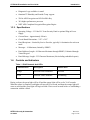
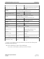
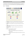
ST-EG100-E Installation and User Guide • Diagnostic Logs available via email • Omnistat2™ Humidity and Outside Temp. support • 256 bit AES Encryption and 1024 bit RSA Key • 30% higher performance processor • NIST AES Compliant Encryption/Decryption Engine Introduction 1.3.2. Specifications • Operating Voltage - 12 Volts D.C. from Security Panel or optional Plug-in Power Supply • Current Draw - Approximately 300 mA • Circuit Board Dimensions - 2.25" x 3.95" • Email Recipients - Limited by Service Provider, typically 16 destination for each sent email • Messages - 16 Maximum, limited by ElkRP2 • Email Address Length - 48 Character Maximum through ElkRP2, Unlimited through Virtual Keypad • Email Message Length - 255 Character Maximum (Not including embedded reports) 1.4. Controls and Indicators Table 1 - RJ-45 Network Jack LEDs LED Indicators Description Normal State Orange Processor Power Indicator On-Solid Green Network Traffic Indicator On-Blinking During a reboot, the green light will be off and the orange light will be on for 30-45 seconds. When the reboot is complete, both lights will turn off for a second, and then the orange light will come on solid and the green light will begin to blink. Wait several seconds before re-establishing a connection with the control. SETECH Security & Automation 96-300001 Revision 1 Page 5 of 44 ST-EG100-E Installation and User Guide Introduction 1.5. Conventions The following conventions are used throughout this document: ! WARNING ! CAUTION Information that must be obeyed in order to avoid injury. Information that must be obeyed in order to avoid damage to product or test equipment. NOTE: Information provided to convey important aspects of the procedure, improve reader understanding, or simplify a task. 1.6. Glossary of Terms DHCP (Dynamic Host Configuration Protocol) - A standard method for assigning IP addresses automatically to the devices on a TCP/IP network. As a new device connects, the DHCP server assigns an IP address from a list of available addresses. The device retains this IP address for the duration of the session. Once the device disconnects the IP address becomes available for use again. DDNS (Dynamic Domain Name System) - Dynamic DNS is a system for allowing an Internet domain name to be assigned to a varying IP address. This makes it possible for other sites on the Internet to establish connections to the machine without needing to track the IP address themselves. A common use is for running server software on a computer that has a dynamic IP address (e.g., a dial-up connection where a new address is assigned at each connection, or a DSL service where the address is changed by the ISP occasionally). DNS (Domain Name System) - A DNS server lets you locate computers on a network or the Internet (TCP/IP network) by domain name. The DNS server maintains a database of domain names (host names) and their corresponding IP addresses. DSL (Digital subscriber line) - Type of broadband connection that brings information to homes and businesses over ordinary copper telephone lines. Encryption - Process of obscuring information to make it unreadable without special knowledge. Information is converted into a code language before it is sent. The receiver has the same software and decodes the information after it arrives. SETECH Security & Automation 96-300001 Revision 1 Page 6 of 44 ST-EG100-E Installation and User Guide Introduction Router- A communications device between networks that determines the best path between them for optimal performance. Routers are used in complex networks such as enterprise-wide networks and the Internet. IP Address (Internet Protocol Address) - The address of a computer attached to a TCP/IP network. Every client and server station must have a unique IP address. (Example: 192.168.0.1). • "Static" IP Address - a permanent or non-changing IP address that is assigned to a node in a TCP/IP network. Static IP addresses are generally used for servers, routers, etc. • "Dynamic" IP Address - an IP address that is automatically assigned to a client station in a TCP/IP network, typically by a DHCP server. ISP (Internet Service Provider) -Provides access to the Internet for others via some connectivity service(s). This might be in the form of dial up services, web hosting services or the combination of both. LAN (Local Area Network) - A computer network covering a local area, like a home, office or small group of buildings such as a college. MAC Address - Unique number assigned by the manufacturer to identify each network interface on all network devices. The first few digits of a MAC address typically identify the manufacturer. The remaining digits uniquely identify the specific interface on that individual device. Also known as a "physical" address. (Example: 00:40:9D:25:6E:C0) NTP (Network Time Protocol) - The protocol for requesting and receiving the current time from a time server. Port - The identifier used by Internet transport protocols to distinguish among multiple simultaneous connections to a single destination host. SMTP (Simple Mail Transfer Protocol) - Internet standard protocol used to transfer electronic mail from one computer system to another. SSL (Secure Socket Layer) - An encryption protocol for transmitting documents securely over the Internet by electronically authenticating each end of an encrypted transmission. Time Server – A computer on the Internet that responds with standard universal time information to time requests. TCP/IP (Transmission Control Protocol/ Internet Protocol) - The basic communication protocol of the Internet. This is a standard for routing and data transfer around the world. The Internet Protocol is a connectionless protocol which provides packet routing. TCP is connectionoriented and provides reliable communication and multiplexing. URL (Uniform Resource Locator) - A string of characters that represents the location or address of a resource on the Internet and how that resource should be accessed. World Wide Web pages SETECH Security & Automation 96-300001 Revision 1 Page 7 of 44 ST-EG100-E Installation and User Guide Introduction are assigned a unique URL. Also known as an Internet address or web address. (Example: http://www.setechautomation.com) WAN (Wide Area Network) - A computer network covering a wide geographical area, involving vast array of computers. The best example of a WAN is the Internet. SETECH Security & Automation 96-300001 Revision 1 Page 8 of 44 ST-EG100-E Installation and User Guide Chapter 2 Installation Installation 2.1. Installing ST-EG100-E Ethernet Gateway 1. Remove power from the M1 Control board before making any connections. 2. Mount the ST-EG100-E to your existing Structured Wiring Box using the two (2) ELK-SWG Circuit Board Guides, or the ELK-SWP3 Multipurpose Adapter Plate, or four (4) ELK-SWNS1 Nylon Standoffs (see Figure 1). The ST-EG100-E should be mounted within 10 feet of the M1 Control. The supplied cable is 16” long. For locating the ST-EG100-E further from the panel, an optional serial cable may be ordered directly from SETECH. DC Power Connector RJ45 Network Jack DB9 Serial Male Connector Mounting Hole (Typical for 4.) Figure 1 - SETECH ST-EG100-E Ethernet Gateway Board 3. Connect the female end of the supplied DB9M serial ribbon cable to the male DB9 connector on the ST-EG100-E, and connect the other end of the ribbon cable to an Elk™ M1™ control board as follows: • For the M1 Gold control board, connect to female DB9 connector (port 0). • For the M1EZ8 control board, connect to the female DB9 connector (port 0) on the M1EZ8MSI Main Serial Port board. SETECH Security & Automation 96-300001 Revision 1 Page 9 of 44 ST-EG100-E Installation and User Guide Installation NOTE: The baud rate of the Control's serial port must be set to 115,200, which is the factory default. 4. Plug one end of a user-supplied RJ45 CAT 5 network patch cable into the RJ45 network jack on the ST-EG100-E and the other end to your Ethernet network switch or router. 5. Plug the included SETECH ST-12VPC power cable into the DC power connector on the ST-EG100-E. The center pin of the DC power barrel connector is positive. Optionally, you can plug the SETECH ST-12VPS power adapter into the ST-EG100E. ! CAUTION Using a power cable or adapter other than referenced above may damage the STEG100-E and will void your warranty. 6. If using the ST-12VPC power cable, connect the white lead of the cable to the +VAUX (+12VDC Auxiliary Power) terminal and the black lead of the cable to the NEG terminal on the M1 Control board. Reapply power to the M1 Control board. If using the optional ST-12VPS power adapter, plug its AC power cord into an AC power receptacle. 7. The ST-EG100-E powers up and attempts to link with the Ethernet network. 8. Enroll the ST-EG100-E into the M1 Control using the keypad as follows: a. Access the Installation Programming (Menu 9). b. Select Bus Module Enrollment (Menu 01) and depress the right arrow key to start the enrollment. When the enrollment is complete press the ELK or * (Asterisk) key to exit. NOTE: Since the ST-EG100-E does not connect to the RS-485 data bus on the M1 Control, it does not appear in the list of devices enrolled on the keypad. However, the enrollment process is required to ensure monitoring and reporting errors of the ST-EG100-E. If the ST-EG100-E is removed and to prevent an Ethernet Trouble message being reported, un-enroll the ST-EG100-E by repeating the Bus Module Enrollment process. 9. Proceed to Chapter 3, Configuration. SETECH Security & Automation 96-300001 Revision 1 Page 10 of 44 ST-EG100-E Installation and User Guide Chapter 3 Configuration Configuration 3.1. Background The ST-EG100-E requires the M1 Family of controls firmware version to be 4.3.0 or later. Configuration of the ST-EG100-E is accomplished using the ElkRP2 software version 1.5.0 or later. Prior to configuration, update to the latest version of the ElkRP2 software, available from the M1 Dealer Website (www.elkproducts.com). The initial setup of the ST-EG100-E requires the computer running ElkRP2 and the ST-EG100-E to be on the same local network. Neither the ElkRP2 nor the SETECH’s Firmware Updater can “find” an ST-EG100-E outside of the local area network. The ST-EG100-E is shipped with DHCP enabled. If a DHCP server exists on your network the ST-EG100-E will obtain a “dynamic” IP address, gateway address, and subnet mask allowing it to work on the local network. If not, the factory programmed (default) IP address 192.168.0.251 is used. If desired, the ST-EG100-E can be configured with a “static” (non-changing) IP address using ElkRP2. 3.2. Prerequisite Prior to configuring the ST-EG100-E, ensure that the M1 Control is programmed to transmit ASCII strings at 115,200 baud for each of its available conditions to allow the Control and the Virtual Keypad to have and display the information. Using the Keypad Installer Programming, or the ElkRP2 software, access the Globals Menu (Menu-07) and program yes for options 35, 36, 37, 38, 39, and 40. Verify that Option 34 is set to 115,200. 3.3. Initial Network Setup A DHCP enabled router does not require any additional configuration to allow the ST-EG100-E to connect inside the local network. For communications outside the local network you will need to forward several open ports on the router. Please refer to section 3.5 and the documentation for your specific router for more details. 1. Start the ElkRP2 software and double-click on the appropriate Account name. The system displays the message “Retrieving account information…” in a pop up window, and then displays the Account Details panel. 2. In the Account Details panel, activate the M1XEP Setup button located at the lower right corner of the panel. The system displays the M1XEP Setup window with the Introduction tab selected. 3. Activate the Find button located along the bottom of the M1XEP Setup window. The system searches for all SETECH ST-EG100-E and Elk M1XEP devices connected to the local area network (LAN), and will display the results in the Find M1XEPs window (see Figure 2). Typically, only a single device is listed. However, if multiple devices are installed on the LAN all should be listed. SETECH Security & Automation 96-300001 Revision 1 Page 11 of 44 ST-EG100-E Installation and User Guide Configuration If no device is listed, activate the Search button to repeat search process. If a device is still not listed, verify hardware was properly installed and enrolled per Section 2.1. Figure 2 – ElkRP2 Find Results 4. Verify the listed MAC address for the device matches the MAC address printed on the label on top of the RJ45 connector on the ST-EG100-E (see Figure 3). If not, repeat the Find/Search function described in step 3. Figure 3 - MAC Address Label Example If the router on the LAN is serving DHCP and the ST-EG100-E is set for DHCP, a dynamic IP address is assigned to the ST-EG100-E by the router. This address is used to communicate with the ST-EG100-E. NOTE: If router DHCP server is disabled or unavailable, the ST-EG100-E defaults to the previously configured static IP address or, if no static address was previously configured, the factory default IP address of 192.168.0.251. 5. Highlight (left-click) the ST-EG100-E device to configure and activate the Use Selected button to copy the IP address and Port settings into the corresponding System URL/IP and Port fields in the ElkRP2 Account Details panel. The system closes the Find M1XEPs window. You should now be able to communicate with the M1 Control. 6. Activate Close button in the M1XEP Setup window to close window. 7. In the Account Details panel, verify the System URL/IP, Port, Serial Number and the RP Access Code fields are correct for the M1 Control. The default RP Access Code is 246801. 8. Select Network from the Connection pull-down menu located at the top of the ElkRP2 window. The system displays a series of messages in a pop up window starting with “Connecting to account using Network” and finishing with “Connecting: verifying system identity”. SETECH Security & Automation 96-300001 Revision 1 Page 12 of 44 ST-EG100-E Installation and User Guide Configuration If successful, the system displays at the lower right corner of the ElkRP2 window. ElkRP2 is now connected to your ELK M1 Control. 9. In the Account Details panel, activate the M1XEP Setup button located at the lower right corner of the panel. The system displays the M1XEP Setup window with the Introduction tab selected. 10. Activate the TCP/IP Settings tab. In the Device Name field, enter a name for the STEG100-E that is used whenever a Find/Search operation is initiated. A maximum of 16 characters may be entered in the Device Name field. 11. Assign a static IP address as follows: By default the ST-EG100-E is set for DHCP and the router assigns a dynamic IP address to the device. Since a dynamic IP address can periodically change, it is recommended that you assign a static IP address to the device to facilitate connecting to the device in the future. a. Select Use a static IP address. b. Contact your network administrator or Internet service provider, and enter the following information as shown in Figure 4. See below for example. • IP Address (e.g. 192.168.14.76). • Subnet Mask (e.g. 255.255.255.0) • Default Gateway (e.g. 192.168.14.70) NOTE: If you switch back to a DHCP server assigning a dynamic IP address, the system reverts to the last programmed static IP address whenever it fails after 1 minute to obtain a dynamic IP address from the DHCP server. 12. Configure DNS addresses as follows: a. Select Specify DNS Addresses to use. b. Contact your network administrator, and enter the following information as shown in Figure 4. • Primary DNS Server (e.g. 192.168.14.1) • Secondary DNS Server Failure to correctly enter the Primary and Secondary DNS servers in order may result in problems with certain features of the ST-EG100-E (email, DDNS, timer server, etc.). 13. Some third party devices use a TCP or non-secure port for standard (unencrypted) communications on the local network. If required, select Enable Non-Secure Port and enter the appropriate port number in the field immediately below (see Figure 4). Valid entries are SETECH Security & Automation 96-300001 Revision 1 Page 13 of 44 ST-EG100-E Installation and User Guide Configuration between 1024 and 49151, with the recommended (default) being 2101. For security reasons, this port should not be mapped outside the local network. If the port is not needed, disable by deselecting Enable Non-Secure Port. 14. ElkRP2 and some third party devices use a SSL or secure port for encrypted communications. Enter the appropriate value for the secure port number in the field immediately below (see Figure 4). Valid entries are between 1024 and 49151, with the recommended (default) being 2601. In order to remotely access the M1 Control from the Internet, your router must be configured to map this port (port forwarded). Refer to documentation for your router to configure port forwarding. Figure 4 – ElkRP2 TCP/IP Settings 15. Activate the Send button to save network configuration changes to the ST-EG100-E and the system displays the M1XEP Reboot Required dialog box (see Figure 5). Figure 5 - Reboot Required Dialog Box 16. Activate Yes button to continue and the system displays a series of messages in a pop up window of the items being sent to the ST-EG100-E. Once all items have been saved, the system displays the M1XEP Reboot Required confirmation dialog box (see Figure 6). SETECH Security & Automation 96-300001 Revision 1 Page 14 of 44 ST-EG100-E Installation and User Guide Configuration Figure 6 - Reboot Required Confirmation Dialog Box 17. Activate OK button and the system displays the Reboot M1XEP dialog box (see Figure 7). Figure 7 - Reboot M1XEP Dialog Box 18. Activate Yes button to reboot the ST-EG100-E to apply the changes. Reboot takes up to 2 minutes to complete, and a connection can not be re-established with the ST-EG100-E until reboot is complete. If the network address configuration has been changed, it will be necessary to update the ElkRP2 configuration as described previously. 19. Select Save Account from the File pull-down menu located at the top of the ElkRP2 window to save all changes to the ElkRP2 database. SETECH Security & Automation 96-300001 Revision 1 Page 15 of 44 ST-EG100-E Installation and User Guide Configuration 3.4. Optional Configuration Using ElkRP2 3.4.1. Setup of User Names & Passwords If you will be remotely connecting to the M1 Control via a web browser (Virtual Keypad), it is REQUIRED that you assign at least one user names with passwords to protect against unauthorized access to the M1 Control from the Web Brower. In addition, third party software developers wishing to connect to the ST-EG100-E secure port typically use the user name and password function. 1. Connect to the ST-EG100-E from ElkRP2. 2. Activate the Passwords tab in the M1XEP Setup window. 3. Enter up to eight (8) different User names and Passwords. Each entry may be up to 16 alphanumeric characters in length. 4. Activate the Send button to save User Names & Passwords configuration changes to the STEG100-E. Refer to steps 15 through 19 of Section 3.3 for instructions on sending changes to ST-EG100-E and saving to local ElkRP2 database. 3.4.2. Setup Email Notification To be notified via email for defined events (e.g. system disarmed by a specific user), setup email notification as follows: 1. Connect to the ST-EG100-E from ElkRP2. 2. Activate the Email tab in the M1XEP Setup window. 3. Enter the outgoing SMTP server’s URL or IP address in the “Server URL/IP Address” field (e.g. smtp.gmail.com). This field supports a maximum entry of 48 characters. 4. In the “Port” field, enter the port for the outgoing mail server. The default port setting is 25. If necessary, contact your network administrator or Internet provider to request the correct port setting. 5. Enter a valid email address in the “FROM email address” field. This email address appears in all email messages generated by the ST-EG100-E. 6. If required by your Internet Service Provider, enter the “Username” and “Password” to log onto the outgoing email server in the corresponding fields; otherwise, leave these fields blank. 7. Define Email Addresses and corresponding messages in the table in the lower portion of the window. The ElkRP2 supports up to 16 addresses and messages. The maximum length of SETECH Security & Automation 96-300001 Revision 1 Page 16 of 44 ST-EG100-E Installation and User Guide Configuration each email address is 48 characters and each corresponding Message may be up to 255 characters. To enter an email address, left-click in the Email Address cell and enter the email address. 8. Left-click in the adjacent Message cell and enter the message to be sent to the email address. If a specific set of Rules criteria that was defined using the Whenever/And/Then rules programming of the ElkRP2 is met, the message is generated and distributed. Refer to ElkRP2 documentation for instructions on defining Rules. The following is an example of a Rule to send a message to send an email message when the system is disarmed by a particular user. The system sends an email to Mom’s email address ([email protected]) when Mike has arrived home. WHENEVER House (Area 1) STATE BECOMES DISARMED AND LAST USER WAS Mike (User 4) THEN SEND EMAIL MESSAGE 1 TO [email protected] (Email 1) 9. Using the Virtual Keypad (refer to Section 4.4.6.1), the ST-EG100-E provides the unique ability to define email groups that are used to send the same notification to multiple email addresses. For example, creating a group named “Mom & Dad” that includes the email addresses for both mom and dad ([email protected], [email protected]), ensures that both parents are notified when Mike arrives home. 10. Activate the Send button to save Email configuration changes to the ST-EG100-E. Refer to steps 15 through 19 of Section 3.3 for instructions on sending changes to ST-EG100-E and saving to local ElkRP2 database. 11. To send a test email, activate the Test button. Please note that this is the only time the STEG100-E can send an email message while connected to ElkRP2. The ST-EG100-E attempts to send email message 1 to the recipient listed for that message. After a few minutes, check the recipient’s inbox to verify receipt of email. 3.4.2.1. Enhanced Email Notification (EEN) Another advanced feature of the ST-EG100-E is that the user can define detailed contents for each email message sent for a specific event (e.g. Area House is disarmed by user Mike), along with ability to send the message to additional users. Embedded dynamic reports such as Zone Status, Zone Alarm, and Area Status may also be included in the body of HTML format email messages. The following is a list of keywords used to define the contents and distribution of an email message. These keywords are entered in the “Message” field. Each keyword is enclosed by matching delimiters, i.e. curly brackets “{“ and “}”. SETECH Security & Automation 96-300001 Revision 1 Page 17 of 44 ST-EG100-E Installation and User Guide Keyword {EMAIL_ALSO=recipients} Examples Keyword {EMAIL_SUBJECT=text} Example Keyword {DEVICE_NAME} Example Keyword {EMAIL_ID} Example Keyword {ZONE_STATUS} Keyword {ZONE_ALARM} Keyword {AREA_ARMING_STATUS} Keyword {DIAGNOSTIC_LOG] Configuration Alternate Keyword Description Add comma separated list of email addresses {EA=recipients} as additional recipients for the email message. {[email protected],[email protected]} {[email protected],[email protected]} Alternate Keyword Description Set the email subject line as specified, {ES=text} replacing the default. {EMAIL_SUBJECT=This is the new email subject} {ES=This is the new email subject} {ES={DN} Confidential system report. Message {EI}} Alternate Keyword Description Insert the device name defined in the {DN} network configuration tab. See {EMAIL_SUBJECT} for example. Alternate Keyword Description Insert the email message number for this {EI} email. See {EMAIL_SUBJECT} for example. Alternate Keyword Description Insert a zone status report in the email {ZS} message. Refer to Section 3.4.5 for advanced filtering of reports. Alternate Keyword Description Insert a zone alarm report in the email {ZA} message. Alternate Keyword Description Insert an area arming status report in the {AAS} email message. Alternate Keyword Description Include diagnostic log in the email {DL} message.* * To simply view the diagnostic log in your web browser, enter either of the following in the URL address field in the browser: http://address/admin/log.txt or https://address/admin/log.txt ;where address is the IP address or DNS name for the ST-EG100-E. SETECH Security & Automation 96-300001 Revision 1 Page 18 of 44 ST-EG100-E Installation and User Guide Configuration Message Example The following is an example of a complex email message set up in the ElkRP2, M1XEP Setup window for a Device Named “ST-EG100-E” with Email Address for Message 1 of “[email protected]. The “FROM” email address defined in M1XEP Setup is [email protected]. Message Definition {ES=[{DEVICE_NAME}] Custom Subject Test for Email {EI}}A test email for multiple recipients and custom subject, with embedded reports for {DEVICE_NAME}. {[email protected]}{ZS}{ZA}{AAS} SETECH Security & Automation 96-300001 Revision 1 Page 19 of 44 ST-EG100-E Installation and User Guide Configuration Resulting Email Email Header: From: [email protected] To: [email protected]; [email protected] Subject: [ST-EG100-E] Custom Subject Test for Email 1 Message Body: A test email for multiple recipients and custom subject, with embedded reports for STEG100-E Firmware. Zone Status Report Zone State 1. Front House Door Short 2. Utility Room Open Door 4. Garage Rear Door Short Status Normal Violated Normal Zone Alarm Report Zone 2. Utility Room Door Alarm Type Burglar Entry/Exit 1 Area Arming Status Report Area 1. House 2. Barn Status Armed Away Disarmed State Alarm Armed Burglar Not Ready No Alarm 3.4.3. Dynamic DNS Setup To access an ST-EG100-E on the Internet, you need to know its Public IP Address. The Internet service provider may change that IP address from time to time. Because IP addresses change and are difficult to remember, you can sign up for a free or low-cost service known as Dynamic DNS. This service allows you to select a semi-custom URL and register it to your IP address. When your IP address changes, the DDNS service will update your URL to point to the new address. The ST-EG100-E can be set up to automatically update the DDNS provider when your IP address changes. Before setting up the ST-EG100-E to do this, you must register for a DDNS account. There are several available that will work with the ST-EG100-E. The ST-EG100-E has been tested and proven to work with the following three DDNS providers (although there may be more): • DynDNS www.dyndns.com • No-IP www.no-ip.com SETECH Security & Automation 96-300001 Revision 1 Page 20 of 44 ST-EG100-E Installation and User Guide • Configuration ChangeIP www.changeip.com Any DDNS provider that adheres to the standard protocol used by these DDNS servers would work. Select a DDNS provider and visit their website to sign up for a free account. The free accounts they offer are basic, but sufficient for accessing the ST-EG100-E from the Internet. For additional fees, each provider has “extras” such as letting you select a fully custom URL, email services, etc. The free service allows you to select a URL in one of their “sub-domains.” For example, DynDNS has nearly one hundred sub-domains to choose from, one being “dyndns.org.” You can prepend any name to the front of it (so long as it’s not already taken) such as “MyM1,” giving you the URL “MyM1.dyndns.org.” Please be sure to read and adhere to the provider’s policies. Because they provide the service for free, they must institute rules to prevent abuse of their service. After setting up the account (it may take a day or two for it to begin working), enter the setup information for that account on the Dynamic DNS tab of the M1XEP Setup window in ElkRP2. 1. In the first box, enter the DDNS provider’s update URL. The ST-EG100-E connects to this URL to update the provider whenever the IP address changes. 2. Below that, enter the username and password you chose when setting up the account on the provider’s website. The ST-EG100-E needs this information to log into the provider’s site to perform the updates. 3. In the Host Name box, enter the custom URL you selected (ie. mym1.dyndns.org). 4. The ST-EG100-E can send you or anyone else an email message whenever an error occurs during an update. This is to notify you that your custom URL will not work until the update is successful. To enable this feature, enter the email address in the next box. You must also fill in the necessary information on the Email tab (refer to Email Notification Section 3.4.2). 5. In addition to notifying you of update errors, you may also want to know when a successful update occurs. Check the last box to enable this. 6. SEND the setup to the control, then activate the Test button to test that the ST-EG100-E can contact the DDNS provider. The test does not perform an actual update, as the provider would consider that an abuse of their service. Instead, it simply checks that it can connect to the provider. How the ST-EG100-E DDNS updates work: Every few minutes, the ST-EG100-E “checks in” with the DDNS provider to find its public IP address. When the ST-EG100-E detects that the public IP address has changed, it logs in to the provider’s website and sends a message containing its new IP address. Most providers will delete a free account if it is not updated every month or two. To prevent this, the ST-EG100-E will “force” an update every thirty days even if its public IP address hasn’t changed. If you enabled email notification of updates, you will be notified when this occurs. Most providers consider it SETECH Security & Automation 96-300001 Revision 1 Page 21 of 44 ST-EG100-E Installation and User Guide Configuration an abuse of their service to force an update too often, but they will allow forced updates every thirty days. 3.4.4. Time Server The ST-EG100-E can connect daily to a Time Server on the Internet to synchronize the M1’s or EZ8’s clock. This keeps the control’s clock to within a second of universal standard time. To enable this feature, click the Time Server tab on the M1XEP Setup window in ElkRP2. If you don’t already have or know of a time server to use, click the link provided or go to http://www.ntp.org/s2 to find a time server. Please observe the following rules while doing this: 1. Choose only a “Stratum-2” server. They are intended for public use. “Stratum-1” servers are reserved for use by governments, large institutions, and stratum-2 servers. Synchronizing to a stratum-2 server will be accurate to within a few milliseconds – more than enough for the M1/EZ8. 2. Select a time server that is geographically close to you. Doing so will ensure that no one server is over taxed with requests. 3. If the server you choose lists any restrictions, please observe them. Some restrict use to certain organizations. Others may simply want to be notified by email if you use them. 4. If using the list on the NTP.org website, be aware that the servers are listed by country first, then state or province. Don’t mistake a country abbreviation for a state abbreviation. 5. Enter the URL or IP address of the server in the first box. Select a time of day for the updates. Updates will be performed daily at this time. Select an “off-the-hour” time such as 2:18 AM rather than 2:00 AM. This will reduce the likelihood of a Rule being triggered twice. If the M1/EZ8 is programmed with a Rule that is triggered at 2:00 AM, it may be triggered twice if the time update caused the control to reset its clock back a few seconds before 2:00 AM. If you want to be notified via email when errors occur updating the time, check the check box, and enter your email address on the Dynamic DNS tab (see Dynamic DNS Setup on page 12). You must also fill in the necessary information on the Email tab (see Email Notification Setup on page 9). Local time zone information is filled in automatically from the Sunrise/Sunset settings in ElkRP2’s Automation menu. If you change it there, you will need to SEND the ST-EG100-E setup to the control afterward. SEND the setup to the control, then click the Test button to verify it works. 3.4.5. Advanced Filtering Content of Zone Status Reports {ZONE_STATUS}, {ZS} - Inserts a Zone Status Report Table for all zones and zone status types into the body of the email. {ZONE_STATUS=filter}, {ZS=filter} – Inserts a Zone Status Report for all zones and zone status types meeting filter criteria. • filter is a comma separated list of filter criteria. SETECH Security & Automation 96-300001 Revision 1 Page 22 of 44 ST-EG100-E Installation and User Guide Configuration • The filter criteria consists of zone references by zone numbers and/or zone status values by name. • Zone numbers may be specified as comma separated individual numbers or ranges. • Ranges are specified as a starting number and ending number separated by a '-' (dash). • Zones are numbered from 1 to 208. A zone number value or range must be specified. For all zones, use 1-208. • The accepted zone status filters are ALL, NORMAL, TROUBLE, VIOLATED, and BYPASSED. • Multiple zone status filters may be used, separated by a comma. If no zone status filter value is specified, ALL is assumed. Example ranges: 1,4-7,12 only zone numbers 1,4,5,6,7, and 12 are to be reported Example filter including zone status filtering: 1-208,VIOLATED report only violated zones in the range 1 through 208 1,4-6,BYPASSED,VIOLATED report bypassed or violated for zones 1,4,5, and 6 Syntax for each given example: {ZS=1,4-7,12} or {ZONE_STATUS=1,4-7,12} {ZS=1-208,VIOLATED} or {ZONE_STATUS=1-208,VIOLATED} {ZS=1,4-6,BYPASSED,VIOLATED} or {ZONE_STATUS=1,4-6,BYPASSED,VIOLATED 3.5. Router Setup Notes 3.5.1. Port Forwarding Particular ports must be opened through the router to allow access to the M1XEP through the Internet. You must access the router's setup in order to open (port forward) these ports. The method for this differs from product to product. Some routers use a software utility to access their setup while others can be accessed via a web browser. Consult the router's documentation for complete instructions on this procedure. SETECH Security & Automation 96-300001 Revision 1 Page 23 of 44 ST-EG100-E Installation and User Guide Configuration The table below lists the ports used by the Elk M1XEP that should be port forwarded through the router. Port 2601 Use Routing Encrypted communications port. Configurable by installer. Route outside to connect with ElkRP2 and web TCP browser through Internet/WAN. TCP Elk M1XEP Firmware Updates Route outside if ElkRP2 will connect through FTP or TCP Internet/WAN to download firmware updates to the Elk M1XEP FTP or TCP Web Browser Route outside to connect with web browser TCP through Internet/WAN. TCP Web Browser (encrypted) Route outside to connect with web browser TCP through Internet/WAN. TCP 2601 is the default. 21 Protocol 80 8080 443 8443 3.5.2. Other Ports Used by the Elk M1XEP The following table contains additional ports used by the M1XEP. These ports should not be opened (port forwarded) outside the local network. Port Use Protocol 2362 The Elk M1XEP listens on this port to respond to a "FIND" Command. UDP 2101 Plain text communications port. Configurable by installer. 2101 is default TCP SETECH Security & Automation 96-300001 Revision 1 Page 24 of 44 ST-EG100-E Installation and User Guide Chapter 4 Virtual Keypad Virtual Keypad 4.1. Virtual Keypad Access To access the Virtual Keypad Locally (on the same network), simply enter the IP Address for the ST-EG100-E located in the System URL/IP field on the Account Details page of ElkRP2, Example http://192.168.1.15. By default, this entry is routed to port 80, therefore, explicitly specifying port 80 is not required. If accessing the Virtual Keypad from the internet (outside the local network), you must open port 80 (port forward). See section 3.5 for additional information for setting up your internal router. 4.2. Web Login The first page of the Virtual Keypad is the Web Login Authentication Page. This login authentication is performed by the ST-EG100-E and acts as a firewall, preventing unauthorized access to the Elk M1 Control. Usernames and Passwords are configured on the Password tab of the M1XEP setup screen of the ElkRP2. By checking the “Save Login Information” box, following the initial entry of a valid Username and Password, this screen will be bypassed. Figure 8 - User Authentication 4.3. Security Panel Login After successfully entering the web login, the next page displayed is the security panel login. This login is required to successfully connect to the security panel. The user code is a 4-digit or 6-digit (system dependent) code as defined in the Users folder of ElkRP2. This code is validated by the security panel and the available features presented in subsequent pages are dependent on the defined user code capabilities. SETECH Security & Automation 96-300001 Revision 1 Page 25 of 44 ST-EG100-E Installation and User Guide Virtual Keypad Figure 9 - User Code Entry The only valid characters are the number 0 through 9. All other entries are to be ignored. The login process is initiated by the Connect button or pressing Enter. On failure, a message is displayed that indicates a general failure, and the entered user code must be re-entered. 4.4. Security System Interface After successfully authentication by the Elk M1 security panel, the user is presented with the Virtual Keypad - Security tab keypad interface. 4.4.1. Security Page The Security interface displays overall system status and provides many of the operations that are available from a physical keypad. Selections are available for choosing the “Area” and “Keypad” configured on the security panel. The area selection allows selecting the area to display and control. Areas restrictions are based on the user code entered to initially access the keypad interface. By default, information for the first authorized area is displayed. The active area can be changed by selecting from the “Area” option menu. The keypad selection allows for selecting any named keypad assigned to the currently selected area. The selection of a keypad gives access to that keypad’s defined function key (F-key) operations. SETECH Security & Automation 96-300001 Revision 1 Page 26 of 44 ST-EG100-E Installation and User Guide Virtual Keypad Area Menu - Presents a list of defined areas. Displayed status and all security related functions are directed to the currently selected area. Keypad Menu - Presents a list of keypads assigned to the selected area. Virtual Keypad button functionality is configured for the specified keypad. Arming Status LEDs • Armed – Displays solid red when the system is in an armed state. • Ready - Displays solid green when the system is ready to be armed. If any zone is not in a “ready state” this indicator will be shown is a disabled state (grey). Auxiliary Buttons • Refresh - Forces a refresh of all system settings. This can be used to repaint the screen in the event of a communications failure. • Status - The “Status” button displays all zones defined in the currently selected area by name, along with their status and state. Valid statuses are “Normal”, “Bypassed”, or “Violated”. Valid states are “Short”, “Open”, or “EOL”. The “Close” button returns the Virtual Keypad back to the keypad display. SETECH Security & Automation 96-300001 Revision 1 Page 27 of 44 ST-EG100-E Installation and User Guide • Virtual Keypad Bypass - Opens a dialog to allow the user to bypass a zone. Zones may only be bypassed when the system is not armed. All Bypassed zones are cleared once the system is disarmed. The Bypass button will be illuminated when any zone is bypassed. Activating the checkbox for each respective zone and clicking on “OK” will toggle its bypass state. o Ignore - Zone is currently being monitored. Activating checkbox will place the zone in “bypass” mode. o Monitor - Zone is currently in “bypass” mode. Activating checkbox will place the zone in “un-bypass” mode. • Instant - Allows the user to set the current arming mode to instant. “Instant” mode forces an immediate alarm if an entry zone is violated. This button can only be activated during the exit delay countdown. SETECH Security & Automation 96-300001 Revision 1 Page 28 of 44 ST-EG100-E Installation and User Guide Virtual Keypad • More... - Allows the user to scroll messages displayed on the first line of the alphanumeric display. This button has no effect if the status consists of a single line. • Function Buttons o F1 thru F6 - Executes the pre-configured function associated with the key. o Exit – Illuminates when the system is ARMED in AWAY Mode. If configured to act as a control within ElkRP2, this button will place the system in “Away” mode. Subsequent clicks during the arming process will place the system in the next configured exit mode. o Stay – Illuminates when the system is ARMED in STAY Mode. If configured to act as a control within ElkRP2, this button will place the system in “STAY” mode. Subsequent clicks during the arming process will place the system in the next configured stay mode. 4.4.2. Lighting Page The lighting interface shows the current state of the defined lighting devices that have their “Show” state set within ElkRP2 and allows setting of the lighting state. The current lighting state is shown by an ON/OFF indicator that illuminates green when the light is on and gray if the light is off. In addition, a sliding scale is shown to indicate the current selected light level – from 0% to 100%. The current light state can be changed by clicking on the ON/OFF indicator or dragging the slider control. When clicking on the indicator, the light will toggle from on to off or off to on. When the light is toggle on, it will be at 100% level. Moving the slider will directly set the light level to the relative slider position. SETECH Security & Automation 96-300001 Revision 1 Page 29 of 44 ST-EG100-E Installation and User Guide Virtual Keypad • ON/OFF Status Button - Shows the current state (on = green, off = grey) of the associated lighting component. Clicking on the indicator will toggle the current state of the component. • Dimmer Slider - Adjusts the brightness of the associated lighting component. This functionality is applicable only to dimmer type components, otherwise, setting to zero will turn off the component and any non-zero value will turn the component on. • Timer Enable Checkbox - All checked components will be configured to turn on/off for the specified amount of time. • Toggle device state (Automatic on/off time) - Allows checked components to be turned on/off for the specified amount of time. The maximum supported time is 2 hours, 46 minutes and 39 seconds (9999 seconds). • Set Time Button - Requests the checked components be turned on/off for the specified amount of time. 4.4.3. Climate Page The climate display shows the current state of thermostats interfaced to the system and allows control of the thermostat settings. By default, the first defined thermostat is displayed. An option menu allows the selection of different thermostats for display and control, if installed. The current temperature is displayed, along with the thermostat operating mode, fan setting, and heating and cooling set points. The thermostat operating mode and fan setting may be modified by selecting a new value from the drop down menus. The heating and cooling set points may be changed by using the up/down arrows to raise/lower the set point. SETECH Security & Automation 96-300001 Revision 1 Page 30 of 44 ST-EG100-E Installation and User Guide Virtual Keypad The valid modes for the thermostat operation are thermostat dependent, however, typically, they are “Off”, “Heat”, “Cool”, “Auto”, and “Emergency Heat”. The valid modes for the fan are “Off”, “On”, and “Auto”. Note: the fan “Off” state is only valid if the thermostat mode is “Off”. 4.4.3.1. Thermostats • Thermostats - Presents a list of available thermostats connected to the system. • Temperature - Ambient temperature of the currently selected thermostat. • Humidity - Relative humidity of the currently selected thermostat (Omnistat2 only). • Outside – Remote Probe temperature of the currently selected thermostat (Omnistat2 only). • Heat/Cool Setpoint - Temperature at which the associated system will be activated. • Mode - Selects the thermostat control mode. ¾ Off - Disables climate control. ¾ Heat - Prevents the ambient temperature from falling below the heating setpoint. ¾ Cool - Prevents the ambient temperature from rising above the cooling setpoint. SETECH Security & Automation 96-300001 Revision 1 Page 31 of 44 ST-EG100-E Installation and User Guide Virtual Keypad ¾ Auto - Maintains the ambient temperature between the heating and cooling setpoints. ¾ Emergency Heat - Forces use of heating coils on heat pump furnaces. This mode has no effect for non-heat pump units. • Fan - Controls the blower operation. ¾ Auto - Fan is cycled on/off based on the operation mode and setpoints. ¾ On - Fan runs continuously. ¾ Cycle - Fan is cycled on and off (based on the configuration of the thermostat) to circulate the air (Omnistat2 only). • Hold - Controls program schedule temperature settings. ¾ Off - Thermostat responds to program schedule temperature setting changes. ¾ On - Thermostat ignores program schedule temperature setting changes. ¾ Vacation - Thermostat ignores program schedule temperature setting changes for the duration of the scheduled away time (Omnistat2 only). 4.4.3.2. Temperature Probes SETECH Security & Automation 96-300001 Revision 1 Page 32 of 44 ST-EG100-E Installation and User Guide Virtual Keypad Shows the reported temperature of available temperature probes. A value of -- indicates the zone is configured as a thermometer but isn’t reporting a valid value. 4.4.3.3. Keypads Shows the ambient temperature of all keypads. As with temperature probes, invalid values (keypads not equipped with temperature probes) will be displayed as double dashes. 4.4.4. Tasks Page The tasks display presents a list of the named tasks from the system with the “Show” option enabled. A task can be activated by pressing the button indicator beside the task. The indicator will illuminate to indicate the task request has been made. The indicator extinguishes when the system has acknowledged the task request. SETECH Security & Automation 96-300001 Revision 1 Page 33 of 44 ST-EG100-E Installation and User Guide Virtual Keypad Displays a list of system defined macros. Macros are defined using the ELK configuration tool and can be used to automate operations (e.g. set all lights to a specific level). Clicking on the status LED requests the task be activated and at that time the LED will turn green. Once the request has been acknowledged, the LED will return to its original state. 4.4.5. Outputs Page The output display shows the current state of the system defined outputs with the “Show” option enabled. By default, only the first 32 available outputs are displayed. To display outputs 64 to 208, the “Show Output >32” check box needs to be selected within ElkRP2. The outputs are displayed in a list by output number, with their assigned name and the current state of the output. Selecting an output from list will highlight that output and update the displayed output state. The current state is shown by a green indicator for an output that is on or a gray indicator for an output that is off. The selected output state can be toggled from on to off or off to on immediately by clicking on the output state indicator. Additionally, the output state can be turned on for a specified duration by specifying the duration in hours, minutes and seconds using the input boxes and selecting the “Turn On” button. SETECH Security & Automation 96-300001 Revision 1 Page 34 of 44 ST-EG100-E Installation and User Guide Virtual Keypad • Status Button - Shows the current state (on = green, off = grey) of the selected output. If no output is selected, the label next to the Status Button will be blank. Clicking on the Status Button causes the output state to be toggled. • Turn On - Requests the selected output be turned on for the specified amount of time. • Show Outputs > 64 - Controls whether or not the upper group of un-named outputs are shown. SETECH Security & Automation 96-300001 Revision 1 Page 35 of 44 ST-EG100-E Installation and User Guide Virtual Keypad 4.4.6. Tools Page 4.4.6.1. Email The Email page is used to expand the email recipient list found within ElkRP2. By specifying a “alias” label matching the Group Name, a single Message may be sent to multiple email recipients. • Group Name - An alias used to expand the “Email Address” column in the Elk RP2 - M1EXP Setup dialog. If a matching “label” is found in the email configuration table the corresponding message will be sent to the associated addresses. • Recipients - Email mailing list. Multiple email addresses are separated by a “,”. • Add - Opens the “Add Group” dialog window and recipients defined one per line. SETECH Security & Automation 96-300001 Revision 1 Page 36 of 44 ST-EG100-E Installation and User Guide Virtual Keypad • Delete - Opens the “Confirm Delete” dialog window for the currently selected entry. • Edit - Opens the “Edit Group” dialog window for the currently selected entry. • Save - Stores the current alias table on the Ethernet module server. SETECH Security & Automation 96-300001 Revision 1 Page 37 of 44 ST-EG100-E Installation and User Guide 4.4.6.2. Virtual Keypad Log Displays the contents of the ELKM1 event log. • ID - Index into the system log table (maximum of 512 log entries). • Date - Date/time the system event was recorded. • Area - Area in which the event occurred. • Event - Brief description of the system event followed by the event and “extended data” codes in brackets (refer to ELK documentation for more detailed information). SETECH Security & Automation 96-300001 Revision 1 Page 38 of 44 ST-EG100-E Installation and User Guide 4.4.6.3. Virtual Keypad License Allows the user to enter a license key. By default, if no license key has been installed on the Ethernet module web server, the server will generate a 15 day temporary license. If the license is allowed to expire the virtual keypad will no longer be available and the user will be presented the following when attempting a connection: SETECH Security & Automation 96-300001 Revision 1 Page 39 of 44 ST-EG100-E Installation and User Guide Maintenance & Troubleshooting Chapter 5 Maintenance & Troubleshooting 5.1. Firmware Installation If you are notified of a new firmware release, you can obtain the file and update the SETECH ST-EG100-E Ethernet Gateway. NOTE: To be notified when a firmware update is available, you must have setup a user account on the setechautomation.com website at the time you purchased ST-EG100-E Ethernet Gateway. 1. Contact SETECH customer service and request the current version of the SETECH Advanced Featured Firmware. 2. Once your information has been verified, you will be sent an email containing a link to the firmware installation package specific for your Ethernet Gateway. Note, this link will allow the download of an encrypted file compatible only with the hardware originally purchased. 3. Using the provided link, download and save the firmware installation package to your local drive and uncompress the contents of the installation package. The uncompressed installation package includes both the firmware installation application (i.e. SETECH-Uploader.exe), and the SETECH firmware binary files. 4. Double-click on the SETECH_Uploader.exe icon to start the installation. The system displays the SETECH Updater window (see Figure 10). Figure 10 - SETECH Updater Window 5. Activate the Discover… button. The updater queries the local network for any SETECH STEG100-E and Elk M1XEP Ethernet boards, and returns a list of all discovered Ethernet boards (see Figure 11). SETECH Security & Automation 96-300001 Revision 1 Page 40 of 44 ST-EG100-E Installation and User Guide Maintenance & Troubleshooting Figure 11 - SETECH Updater Discovery Window 6. Left-click to highlight the Ethernet board to update, and activate the Select button. NOTE: For most security systems, only a single Ethernet board is listed. 7. Activate the File… button and browse to select the firmware binary file to install. The binary file includes the last 6 characters of the MAC address of the Ethernet hardware. In the example shown, the binary file for the Ethernet board with a MAC address of 00:40:9D:69:51:FF would be STEG100E_6951FF.bin. The filename and path is loaded into the Image entry box in the SETECH Updater window. 8. Activate the Update button to start the update process (see Figure 12). CAUTION ! The update process takes several minutes to complete. Do not interrupt or remove power from the Ethernet board until the update process is complete. An interruption of the update process may result in the Ethernet board becoming non-responsive. If the update process is interrupted, repeat update process starting at step 6. If the Ethernet board is unresponsive and the update process cannot be restarted, refer to Section 5.2 for troubleshooting information. Figure 12 – Operating System Firmware Update In Process 9. At the completion of update process, the system displays the message “Update complete” at the bottom of the SETECH Updater window. SETECH Security & Automation 96-300001 Revision 1 Page 41 of 44 ST-EG100-E Installation and User Guide Maintenance & Troubleshooting 10. Activate Exit button to close the SETECH Updater window. 5.2. Troubleshooting Symptom ElkRP2 cannot "Find" the ST-EG100-E Cause Resolution Verify the ST-EG100-E is powered up and connected to the M1 Control. Wait 2 minutes after powering up the STEG100-E for the initialization process to complete before ElkRP2 can "Find" the STEG100-E. Network cable disconnected. Verify all cable connections and check to see if green LED on the RJ45 connector is blinking, indicating network traffic. Serial communications not configured properly. Check the serial baud rate in the M1. This setting can be accessed through the keypad, by entering Menu 9- Installation Programming, or SubMenu. Global System Definitions. Global option G34 should be set to 115200 SETECH Security & Automation 96-300001 Network router is not serving IP addresses or the ST-EG100-E is set to a static address. Use a crossover cable to connect directly from the PC to the ST-EG100-E. This will require making some changes to the network setup of the PC to allow the PC and the ST-EG100-E to be in the same subnet. ST-EG100-E listens on port 2362 to respond to a "FIND" Command. If there is a router/firewall between the PC and the ST-EG100-E, it must port forward port 2362. Revision 1 Page 42 of 44 ST-EG100-E Installation and User Guide Symptom Maintenance & Troubleshooting Cause Resolution Using ElkRP2, click on M1XEP setup, then click "Find" to verify IP address. Highlight the ST-EG100-E and click "Use Selected" If the ST-EG100-E does not appear on the find screen, refer to the troubleshooting steps above. If there is a router/firewall between the PC and STEG100-E, it must port forward port 2601. Cannot connect with ElkRP2 via Local Network Encrypted communications port 2601 not configured. For ST-EG100-E firmware updates, port 21 must also be port forwarded through the router. Ensure that a connection can be established on the local network. Cannot connect with ElkRP2 via Internet/WAN. Verify router settings- the router must port forward port 2601. For ST-EG100-E firmware updates, port 21 must also be port forwarded through the router. If using a DDNS service, any changes to the “dynamic” name may require time to propagate through the entire internet system. Depending on the service, this could even take 1 or 2 days. Follow steps above for ElkRP2 connections. Cannot connect to Web Browser ST-EG100-E will not send emails Router not properly configured to connect with web browser TCP through Internet/WAN. Router must port forward ports 80 (or other HTTP/HTTPS port). Verify "From" address is valid. Verify Mail server DNS/IP address and Port. If server requires login, verify the username and password. Verify Primary and Secondary DNS servers are entered SETECH Security & Automation 96-300001 Revision 1 Page 43 of 44 ST-EG100-E Installation and User Guide Symptom Maintenance & Troubleshooting Cause Resolution correctly on the TCP/IP tab of the M1XEP setup and that the DHCP configuration is correct for automatically obtaining the DNS information. Verify the Rule to send email is written correctly. Verify that ElkRP2 is disconnected when the triggering event occurs. Ethernet Trouble SETECH Security & Automation 96-300001 Verify the ST-EG100-E is connected to the M1 and enrolled. Revision 1 Page 44 of 44