1
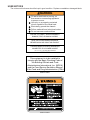
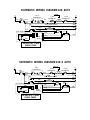
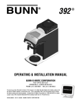
A10 Automatic &
A10A Automatic
Supplement to A10 Use & Care
Booklet #10070.0000
INSTALLATION & OPERATION
INTRODUCTION
This equipment will automatically brew a 48 ounce batch of coffee into an awaiting decanter and has
a pour-over feature for emergency use. It is only for indoor use on a sturdy counter or shelf.
BUNN-O-MATIC COMMERCIAL PRODUCT WARRANTY
Bunn-O-Matic Corp. (“Bunn”) warrants the equipment manufactured by it to be commercially free from defects in material and
workmanship existing at the time of manufacture and appearing within one year from the date of installation. This warranty does
not apply to any equipment, component or part that was not manufactured by Bunn or that, in Bunn’s judgement, has been affected
by misuse, neglect, alteration, improper installation or operation, improper maintenance or repair, damage or casualty.
THE FOREGOING WARRANTY IS EXCLUSIVE AND IS IN LIEU OF ANY OTHER WARRANTY, WRITTEN OR ORAL, EXPRESS
OR IMPLIED, INCLUDING, BUT NOT LIMITED TO, ANY IMPLIED WARRANTY OF EITHER MERCHANTABILITY OR FITNESS FOR
A PARTICULAR PURPOSE. The agents, dealers or employees of Bunn are not authorized to make modifications to this warranty
or to make additional warranties that are binding on Bunn. Accordingly, statements by such individuals, whether oral or written,
do not constitute warranties and should not be relied upon.
The Buyer shall give Bunn prompt notice of any claim to be made under this warranty by telephone at (217) 529-6601 or by
writing to Post Office Box 3227, Springfield, Illinois, 62708-3227. If requested by Bunn, the Buyer shall ship the defective
equipment prepaid to an authorized Bunn service location. If Bunn determines, in its sole discretion, that the equipment does not
conform to the warranty, Bunn shall repair the equipment with no charge for parts during the one year warranty period and no charge
for labor by a Bunn Authorized Service Representative during the one year warranty period. If Bunn determines that repair is not
feasible, Bunn shall, at its sole option, replace the equipment or refund the purchase price for the equipment.
THE BUYER’S REMEDY AGAINST BUNN FOR THE BREACH OF ANY OBLIGATION ARISING OUT OF THE SALE OF THIS
EQUIPMENT, WHETHER DERIVED FROM WARRANTY OR OTHERWISE, SHALL BE LIMITED, AS SPECIFIED HEREIN, TO REPAIR
OR, AT BUNN’S SOLE OPTION, REPLACEMENT OR REFUND. Bunn shall not be liable for any other damage or loss, including,
but not limited to, lost profits, lost sales, loss of use of equipment, claims of Buyer’s customers, cost of capital, cost of down time,
cost of substitute equipment, facilities or services, or any other special, incidental or consequential damages.
BUNN-O-MATIC CORPORATION
POST␣ OFFICE␣ BOX␣ 3227
SPRINGFIELD,␣ ILLINOIS␣ 62708-3227
TELEPHONE:␣ (217) 529-6601␣ ␣ FAX:␣ (217) 529-6644
10613.0000C
2/94 ©␣ ␣ 1993␣ ␣ BUNN-O-MATIC CORPORATION.
USER NOTICES
The notices on this brewer should be kept in good condition. Replace unreadable or damaged labels.
!
WARNING
Fill water tank before turning -on
thermostat or connecting appliance
to power source.
Use only on a properly protected
circuit capable of the rated load.
Electrically ground the chassis.
Follow national/local electrical codes.
Do not use near combustibles.
FAILURE TO COMPLY RISKS EQUIPMENT
DAMAGE, FIRE, OR SHOCK HAZARD
READ THE ENTIRE OPERATING MANUAL
BEFORE BUYING OR USING THIS PRODUCT
THIS APPLIANCE IS HEATED WHENEVER
CONNECTED TO A POWER SOURCE
00831.0000F 3/98 © 1988 BUNN-O-MATIC CORPORATION
#00831.0000
This equipment is to be installed to
comply with the Basic Plumbing Code of
the Building Officials and Code
Administrators International, Inc. (BOCA)
and the Food Service Sanitation Manual
of the Food and Drug Administration (FDA).
#00656.0000
#00658.0000
ELECTRICAL REQUIREMENTS
CAUTION - Do not plug-in the brewer until specified in Initial Set-Up.
The A10 Automatic Brewer has an attached cordset and requires 2-wire grounded service rated 120
volts ac, 10 amp, single phase, 60 Hz.
The A10A Automatic Brewer has an IEC 320 connector and matching cordset and requires 2-wire
grounded service rated 230 volts ac, 10 amp, single phase, 50-60 Hz. The appropriate cordset connector
must be supplied when installing the brewer.
PLUMBING REQUIREMENTS
This brewer must be connected to a cold water system with operating pressure between 20 and 90 psi
from a 1/2" or larger supply line. A shut-off valve should be installed in the line before the brewer. Install a
regulator in the line when pressure is greater than 90 psi to reduce it to 50 psi. The water inlet fitting is
1
/4" flare.
NOTE – Bunn-O-Matic recommends 1/4" copper tubing for installations of less than 25 feet and 3/8" for more
than 25 feet from the 1/2" water supply line. At least 18 inches of an FDA approved flexible beverage
tubing, such as reinforced braided polyethylene or silicone, before the brewer will facilitate movement
to clean the countertop. It can be purchased direct from Bunn-O-Matic (part number 00326-0000).
This equipment must be installed to comply with the Basic Plumbing Code of the
Building Officials and Code Administrators International, Inc. (BOCA)
and the Food Service Sanitation Manual of the Food and Drug Administration (FDA).
Plumbing Hook-Up
1.
2.
3.
Attach the flare fitting from the short piece of tubing on the flow control (supplied) to the water inlet fitting
on the left rear side of the brewer.
Flush the water line and securely attach it to the flare fitting on the strainer.
Turn on the water supply.
INITIAL SET-UP
CAUTION – The brewer must be unplugged throughout the initial set-up, except when specified in the
instructions.
1. Insert an empty funnel into the funnel rails.
2. Place an empty decanter under the funnel.
3. Pour three pitchers of tap water into the screened area on top of the brewer. Allow approximately two
minutes between pitchers for water to flow into the tank. While the third pitcher of water is entering the
tank, the tank will fill to capacity and the excess will flow from the sprayhead, out of the funnel, and into
the decanter.
4. When the flow of water from the funnel stops, plug-in the brewer and place the heater switch on the
left side of the brewer in the “ON” lower position. Wait approximately twenty minutes for the water in
the tank to heat to the proper temperature. Some water will drip from the funnel during this time; this
is due to expansion and should not occur thereafter.
5. Empty the decanter, return it to the warmer, place the warmer switch in the “ON” (lighted) position, and
momentarily press and release the start switch.
6. Place the warmer switch in the “OFF” (unlighted) position after water has stopped flowing from the
funnel, and let the water in the tank reheat to the proper temperature.
7. Empty the decanter, place the warmer switch in the “ON” (lighted) position, and momentarily press and
release the start switch. Check the water volume in the decanter after water has stopped flowing from
the funnel. It should be 48 ounces.
INITIAL SET-UP (CONT.)
8.
If not, locate the brew timer near the heater switch on the left side of the brewer, adjust the brew timer
dial up-or-down as required and allow the water to reheat. Start, and measure another brew cycle.
9. Repeat step 8 until 48oz water volume is achieved.
10. The brewer is now ready for use in accordance with the coffee brewing instructions.
OPERATING CONTROLS
Warmer Switch
Placing the switch in the unlighted position cuts power to the brew station warmer and stops brewing.
Stopping a brew cycle after it has been started will not stop the flow of water into the funnel until the tank
syphons down to its proper level. Placing the switch in the lighted position supplies power to the brew station
warmer and enables the brew circuit.
Start
Momentarily pressing and releasing this switch starts a brew cycle when the warmer switch is in the
lighted position.
NOTE – The warmer switch must be in the lighted position to initiate and complete a brew cycle.
Full/Half
Placing this switch in the half position yields approximately 24 ounces.
COFFEE BREWING
1.
2.
3.
4.
5.
6.
Insert a BUNN® filter into the funnel.
Pour the fresh coffee into the filter and level the bed of grounds by gently shaking.
Slide the funnel into the funnel rails.
Place an empty decanter under the funnel.
Place the warmer switch in the lighted position. Momentarily press and release the start switch.
When brewing is completed, simply discard the grounds and filter.
CLEANING
1.
2.
3.
The use of a damp cloth rinsed in any mild, non-abrasive, liquid detergent is recommended for cleaning
all surfaces on Bunn-O-Matic equipment.
Check and clean the sprayhead. The sprayhead holes must always remain open.
With the sprayhead removed, insert the deliming spring (provided) all the way into the sprayhead tube.
When inserted properly, no more than two inches of spring should be visible. Saw back and forth five
or six times.
NOTE – In hard water areas, this may need to be done daily. It will help prevent liming problems in the
brewer and takes less than a minute.
REPLACEMENT PARTS
04060.0000 ........... BASE EXTRUSION
04040.0004 ........... BREW FUNNEL, BLACK
04069.0003 ........... CONTROL THERMOSTAT ASSY.
01716.0000 ........... CORD, POWER 250V 10 AMP, IEC320 (A10A)
01637.0000 ........... CORDSET, 16/3HSJO NEMA 5-15P (A10)
04123.0001 ........... COVER, TOP BLACK
00658.0000 ........... DECAL, CAUTION DECANTER & FUNNEL
21139.0002 ........... DECAL, FRONT END CAP
00831.0000 ........... DECAL, WARNING ELECTRICAL
01193.0000 ........... DELIMING SPRING
04124.0001 ........... FLIP LID, BLACK
01148.0001 ........... FLOW CONTROL & STRAINER ASSY, .222 GPM
20526.0222 ........... FLOW WASHER, .222 GPM
04002.1000 ........... FOOT
21327.0001 ........... FRONT END CAP, BLK
04063.0000 ........... HOOD EXTRUSION, LEFT
04062.0000 ........... HOOD EXTRUSION, RIGHT
04041.0003 ........... HOT WATER FUNNEL, BLACK
04097.0002 ........... POUR-IN BASIN, BLACK AUTO
01908.0000 ........... POWER CONNECTOR, IEC320 (A10A)
04016.0001 ........... REAR END CAP, BLK
01975.0000 ........... SOLENOID VALVE 240V (A10A)
01085.0000 ........... SOLENOID VALVE, 120V (A10)
01075.0000 ........... SPRAYEHAD FITTING NUT
04011.0000 ........... SPRAYHEAD PANEL
04045.0000 ........... SPRAYHEAD, 5 HOLE PLASTIC
01082.0004 ........... SPRAYHEAD, 5 HOLE STAINLESS STEEL
00707.0000 ........... STRAIN RELIEF BUSHING (A10)
04052.0000 ........... SWITCH BRACE
21273.0000 ........... SWITCH, HALF BATCH
04067.0001 ........... SWITCH, LIGHTED ON/OFF 120V (A10)
04039.0000 ........... SWITCH, LIGHTED ON/OFF 240V (A10A)
21274.0000 ........... SWITCH, START
04786.0002 ........... SWITCH, VACATION
05518.0000 ........... SYPHON HUB
04174.0000 ........... TANK HEATER 1000W 240V (A10A)
00943.0000 ........... TANK HEATER GASKET
00942.0002 ........... TANK HEATER NUT
04144.0000 ........... TANK HEATER, 1000W 120V (A10)
01932.0000 ........... TANK KEEP WARM HEATER, 34W 240V (A10A)
04100.0000 ........... TANK KEEP WARM HEATER, 40W 120V (A10)
04142.0000 ........... TANK LID
04844.0000 ........... TANK LID GASKET
00960.0001 ........... TANK LID INLET FITTING
01540.0000 ........... TANK LID INLET FITTING WASHER
01201.0000 ........... TANK LID INLET GASKET
04167.0001 ........... THERMAL CUT OFF W/RED LEADS (A10A)
21453.0000 ........... TIMER BOARD SHIELD
02620.1042 ........... TIMER, 120V 3-BATCH (A10)
02620.1043 ........... TIMER, 240V 3 BATCH (A10A)
04065.0000 ........... TRUNK EXTRUSION, LEFT
04064.0000 ........... TRUNK EXTRUSION, RIGHT
04012.0007 ........... TRUNK REAR, BLK (A10)
04012.0008 ........... TRUNK REAR, BLK (A10A)
21214.0000 ........... TUBE ASSY, FILL BASIN
04095.0003 ........... WARMER ASSY W/LEADS, BLK 80W 230V (A10A)
04095.0002 ........... WARMER ASSY W/LEADS, BLK 80W 120V (A10)
04021.0002 ........... WARMER FRAME, BLACK
04870.0000 ........... WATER PITCHER, 48 OZ
SCHEMATIC WIRING DIAGRAM A10 AUTO
GREEN
L1
SW1
BLK
N
SW. &
THERMOSTAT
LIMIT
THERMOSTAT
BLU
BLK
SW2
BLK
HALF BATCH OPTION
GRY
SW4
PNK
WHI
"KEEP WARM" HEATER
WHI
80W
BLK
LOWER WARMER
1
2
BREW 3
TIMER 4
5
TAN
WHI
TANK HEATER
40W
WHI
1000W
LIMIT
THERMOSTAT
120 VOLTS AC 2 WIRE
SINGLE PHASE
WHI
WHI
SW3
SOL
BLK
WHI
ORA
WHI/GRN
YEL
10628.0001A 5/92 © 1991 BUNN-O-MATIC CORPORATION
SCHEMATIC WIRING DIAGRAM A10 A AUTO
GRN/YEL
L1
SW1
BLK
L2
SW. &
THERMOSTAT
LIMIT
THERMOSTAT
BLK
BLU
40W
WHI
SW2
BLK
HALF BATCH OPTION
GRY
SW4
PNK
TAN
1000W
LIMIT
THERMOSTAT
RED
TANK HEATER
WHI
"KEEP WARM" HEATER
RED
80W
BLK
LOWER WARMER
1
2
BREW 3
TIMER 4
5
230 VOLTS AC 2 WIRE
SINGLE PHASE
RED
RED
SOL
SW3
BLK
RED
ORA
WHI/GRN
YEL
10627.0001A 5/92 © 1992 BUNN-O-MATIC CORPORATION