1
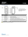
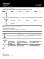
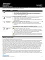
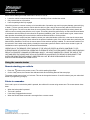
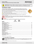
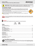
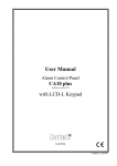
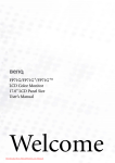
User guide
CANMAX400 Standalone
Revision: 16-Nov-09
Thank you for purchasing a Directed Electronics, Inc. CANMAX400 solution.
CANMAX400 supports multiple data bus architectures including: CAN High speed, CAN Single Wire, CAN Fault Tolerant,
GM-LAN, J1850, ISO, BEAN, FLEXRAY and more. CANMAX400 includes 2 additional "XPANSION" ports. The XKEY
port securely docks XKEYS for RF transponder bypass when a data override is not possible. A relay XPANSION port
supports the addition of an external relay pack for Remote Start Ready solutions. The 2nd generation XKLOADER2 is
required for flashing CANMAX400.
© 2009 Directed Electronics, Inc. All rights reserved.
1
User guide
CANMAX400 Standalone
Revision: 16-Nov-09
Table of contents
Important information ........................................................................................................................................................... 3 Your warranty ................................................................................................................................................................... 3 Replacement remotes....................................................................................................................................................... 3 Caution ............................................................................................................................................................................. 3 Introduction to the system.................................................................................................................................................... 3 2-way remote control ........................................................................................................................................................ 4 1-way remote control ........................................................................................................................................................ 5 Transmitter configuration .................................................................................................................................................. 6 System maintenance ........................................................................................................................................................ 7 Low battery indicator......................................................................................................................................................... 7 Battery replacement.......................................................................................................................................................... 7 Remote control programming .............................................................................................................................................. 7 Warning – Safety first! ......................................................................................................................................................... 8 Using the remote starter ...................................................................................................................................................... 9 Remote starting your vehicle ............................................................................................................................................ 9 Points to remember .......................................................................................................................................................... 9 Manual transmission ....................................................................................................................................................... 10 Power save mode .............................................................................................................................................................. 10 System ............................................................................................................................................................................ 10 2-way remote control ...................................................................................................................................................... 10 Limited one-year consumer warranty ................................................................................................................................ 11 Glossary ............................................................................................................................................................................. 12 © 2009 Directed Electronics, Inc. All rights reserved.
2
User guide
CANMAX400 Standalone
Revision: 16-Nov-09
Important information
Congratulations on the purchase of your state-of-the-art remote start and alarm system. Due to the complexity of this
system, it must be installed by an authorized dealer only. Installation of this product by anyone other than an authorized
dealer voids the warranty. All dealers are provided with a preprinted dealer certificate to verify authorization.
By carefully reading this Owner’s Guide prior to using your system, you will maximize the use of this system and its
features. You can print additional or replacement copies of this manual by accessing our web site at www.directed.com.
Your warranty
Your warranty registration must be completely filled out and returned within 10 days of purchase. Your product warranty
will not be validated if your warranty registration is not returned. Make sure you receive the warranty registration from your
dealer. It is also necessary to keep your proof of purchase, which reflects that the product was installed by an authorized
dealer.
Replacement remotes
Your system comes with two remote controls – one is 2-way while the other is 1-way. If additional remotes are desired,
please see your authorized dealer or visit www.directedstore.com to order.
Caution
This product is designed for fuel injected vehicles only. Use of this product in a standard transmission vehicle must be in
strict accordance with this guide.
Introduction to the system
Some main features of the CANMAX400 system in Standalone mode:
•
•
Vehicle Security.
Door, hood, and trunk* monitoring.
Keyless Entry:
•
•
•
•
Door locking/unlocking via remote control.*
Driver’s door priority unlocking.
Trunk or hatch release.*
Power sliding door control.*
Remote Start:
•
•
Long-range operation.
Hood, brake, and other shutdown inputs.
* May require optional parts or installation labor.
© 2009 Directed Electronics, Inc. All rights reserved.
3
User guide
CANMAX400 Standalone
Revision: 16-Nov-09
2-way remote control
* Your remote control may look
different, depending on which product
you have purchased (Clifford, Python
or Viper); however, the features
remain the same.
Function
Description
1
Transmit indicator
2
LED indicators
Blink to indicate function confirmation.
3
Lock button
Press for one second to arm.
4
Unlock button
Press for one second to disarm.
5
Remote start button
Press for one second to activate remote start.
6
Auxiliary button
Press and hold for 1.5 second to activate optional trunk release.
7
Function button
Allows access to programming and modifies operation of the other buttons.
8
2-way label
Back of remote has a label to identify the remote as 2-way or 1-way.
9
Battery door
Remote to access batteries when necessary. See page 7 for more information.
If keypad lock is on, press
and then press
© 2009 Directed Electronics, Inc. All rights reserved.
to exit.
4
User guide
CANMAX400 Standalone
Revision: 16-Nov-09
1-way remote control
* Your remote control may look
different, depending on which product
you have purchased (Clifford, Python
or Viper); however, the features
remain the same.
Function
Description
1
Transmit indicator
2
Lock button
Press for one second to arm.
3
Unlock button
Press for one second to disarm.
4
Remote start button
Press for one second to activate remote start.
5
Auxiliary button
Press and hold for 1.5 second to activate optional trunk release.
6
Function button
Allows access to programming and modifies operation of the other buttons.
7
1-way label
Back of remote has a label to identify the remote as 2-way or 1-way.
8
Battery door
Remote to access batteries when necessary. See page 7 for more information.
If keypad lock is on, press
and then press
© 2009 Directed Electronics, Inc. All rights reserved.
to exit.
5
User guide
CANMAX400 Standalone
Revision: 16-Nov-09
Transmitter configuration
The following table provides a summary of function levels linked to the remote control button:
Button
x0
x1
x2
x3
AUX 1
AUX 2
AUX 3
Arm
Lock
Disarm
Unlock
Remote start
Remote start
Trunk release
Auxiliary
Function shift
Function
The
button must be pressed and held to access state.
List of commands and confirmations
The following table lists the commands performed by each remote button:
Button
Command
Confirmation
Notes
(2-way remote only)
Press once to arm.
Lock LED blink for one second with
1 beep and siren tone.
Press once to disarm.
Lock LED blink for one second with
2 beeps.
Press once to active
remote start
Remote start LED blinks for 3
seconds, remote start tones.
Press and hold for 1.5
seconds to activate the
trunk release.
The AUX LED comes on for 3
seconds, and AUX activation tone
sounds.
This is an optional feature. See your
sales rep/installer for details.
LED indicators turn on (according to
the feature command.)
Each press and release shifts the
function of the command button.
Arm
Press/hold for 1.5 seconds to Arm
the system and then activate the
Panic output.
Disarm
Remote start
AUX
Function shift
Press one to three
times, and then press
.
Pressing more than one button simultaneously generates an Error tone and the F-Shift LED turns ON.
© 2009 Directed Electronics, Inc. All rights reserved.
6
User guide
CANMAX400 Standalone
Revision: 16-Nov-09
Out of range notification
If a command is issued from the remote, but the remote is beyond the range of the vehicle to receive the command, the
remote will respond with an Out of Range notification. If this occurs, the remote will Blink rapidly the transmit indicator,
turn on the F indicator and play the error tone.
Since conditions will vary in different areas (i.e.: Weather, RF interference, etc) range may be affected and require you to
be closer to the vehicle for successful transmission.
System maintenance
The system requires no specific maintenance. Your remotes are powered by small coin cell lightweight 3-volt lithium
batteries that will last approximately one year under normal use. The 2-way remote uses two CR2016 cell batteries and
the 1-way remote uses one CR2032 cell battery. When the battery begins to weaken, the operating range will be reduced.
Low battery indicator
When the batteries are low on the 2-way remote it will emit two groups of beeps, the LED will flash, and the alarm will
emit an additional chirp to let you know it’s time to change the battery. When the battery is low on the 1-way remote, the
remote responds the same, but without the LED flash.
The Arm/Disarm chirps should be programmed ON for the alarm to emit any additional chirps during disarming. Ask
your authorized dealer if you have any questions.
Battery replacement
Slide the door up to expose the battery beneath the holder. Remove the expired battery. Place the new battery into the
remote control. When power is returned the remote control is ready for use.
Remote control programming
The 2-way remote control has menus for programming the remote to the system control module including adjusting the
control module onboard shock sensor, and for configuring the remote control user features.
To program the remote user features:
1. Press and hold the
button for 12 seconds: (at 3 seconds ignore the Car number indicator.)
2. The remote emits one long beep, and the Transmit LED turns on. This indicates the Main menu.
3. Press and hold the
button for 1.5 seconds:
The remote beeps two-times, and the Transmit LED blinks two-times and stays on. You are now in the Remote
Configuration menu.
The Arm, Disarm, Remote Start & Aux LEDs will turn ON, and/or blink to indicate the current remote feature
configuration. When the LED is ON, the feature is ON.
© 2009 Directed Electronics, Inc. All rights reserved.
7
User guide
CANMAX400 Standalone
Revision: 16-Nov-09
To configure the remote control features press and release the command button. The LED next to the button will turn ON
then OFF. The remote beeps to indicate the feature configuration.
Button
Command
Confirmation
Auto-button lock
•
•
When Arm LED is OFF, buttons will not lock.
LED ON: The buttons automatically lock 60 seconds after the last button operation to
avoid accidental Command operations. When locked, if any command button is
pressed the remote will emit an error output.
If button lock is ON, press
, and then
.
Remote beeps
•
•
•
Runtime low
alert feature
This feature is not available on the 1-way remote.
• Remote Start LED OFF: The remote will ignore Runtime Low Alert messages.
• Remote Start LED ON: The remote will emit feedback output for Runtime Low Alert
messages.
These messages will be automatically sent while Remote Start is ON to alert you when the
runtime remaining is at 3 minutes, and again at 1 minute before shut down.
Page
mode/Power
saver
This feature is not available on the 1-way remote.
Aux LED OFF: The remote will not wake up and listen for messages from the system
to extend battery life. Note: This means the remote will not receive alarm trigger pages.
Aux LED ON: the remote will wake up to listen for messages from the system.
Aux LED blinking: Power saver mode (see note below).
•
•
•
Disarm LED OFF: The remote will not emit beeps except when programming.
Disarm LED ON: The remote will emit beeps normally.
Disarm LED blinking: The remote will emit beeps only for alarm trigger messages from
the alarm system.
Power saver automatically turns off the remote pager if a button on the remote has not
been pressed for more than 72 hours and will be restored after any button on the remote is
pressed.
Warning – Safety first!
The following safety warnings must be observed at all times:
Due to the complexity of this system, installation of this product must only be performed by an authorized Directed dealer.
When properly installed, this system can start the vehicle via a command signal from the remote control transmitter.
Therefore, never operate the system in an enclosed area or partially enclosed area without ventilation (such as a garage).
When parking in an enclosed or partially enclosed area or when having the vehicle serviced, the remote start system must
be disabled using the installed toggle switch. It is the user’s sole responsibility to properly handle and keep out of reach
from children all remote control transmitters to assure that the system does not unintentionally remote start the vehicle.
THE USER MUST INSTALL A CARBON MONOXIDE DETECTOR IN OR ABOUT THE LIVING AREA ADJACENT TO
THE VEHICLE. ALL DOORS LEADING FROM ADJACENT LIVING AREAS TO THE ENCLOSED OR PARTIALLY
ENCLOSED VEHICLE STORAGE AREA MUST AT ALL TIMES REMAIN CLOSED. These precautions are the sole
responsibility of the user.
Remote starters on manual transmission vehicles operate differently than those with automatic transmission because you
must leave your car in neutral. You must read this Owner’s Guide to familiarize yourself with the proper procedures
regarding manual transmission remote starters. If you have any questions, ask your installer or contact Directed at 1-800753-0600.
© 2009 Directed Electronics, Inc. All rights reserved.
8
User guide
CANMAX400 Standalone
Revision: 16-Nov-09
Before remote starting a manual transmission vehicle, be sure to:
•
•
•
Leave the vehicle in neutral and be sure no one is standing in front or behind the vehicle.
Only remote start on a flat surface
Have the parking brake fully engaged
Use of this product in a manner contrary to its intended mode of operation may result in property damage, personal injury,
or death. (1) Never remotely start the vehicle with the vehicle in gear, and (2) Never remotely start the vehicle with the
keys in the ignition. The user must also have the neutral safety feature of the vehicle periodically checked, wherein the
vehicle must not remotely start while the car is in gear. This testing should be performed by an authorized Directed dealer
in accordance with the Safety Check outlined in the product installation guide. If the vehicle starts in gear, cease remote
start operation immediately and consult with the authorized Directed dealer to fix the problem.
After the remote start module has been installed, contact your authorized dealer to have him or her test the remote start
module by performing the Safety Check outlined in the product installation guide. If the vehicle starts when performing the
Neutral Safety Shutdown Circuit test, the remote start unit has not been properly installed. The remote start module must
be removed or the installer must properly reinstall the remote start system so that the vehicle does not start in gear. All
installations must be performed by an authorized Directed dealer.
OPERATION OF THE REMOTE START MODULE IF THE VEHICLE STARTS IN GEAR IS CONTRARY TO ITS
INTENDED MODE OF OPERATION. OPERATING THE REMOTE START SYSTEM UNDER THESE CONDITIONS MAY
RESULT IN PROPERTY DAMAGE OR PERSONAL INJURY. YOU MUST IMMEDIATELY CEASE THE USE OF THE
UNIT AND SEEK THE ASSISTANCE OF AN AUTHORIZED Directed DEALER TO REPAIR OR DISCONNECT THE
INSTALLED REMOTE START MODULE. DIRECTED WILL NOT BE HELD RESPONSIBLE OR PAY FOR
INSTALLATION OR REINSTALLATION COSTS.
Using the remote starter
Remote starting your vehicle
•
•
Press the
button on the remote control. The vehicle parking lights flash.
On the 2-way remote, the Remote Start indicator blinks and ascending Remote Start tone plays.
The preset remote start run time is 12 minutes. This can be changed to between 12 and 60 minutes (see your authorized
dealer for programming changes).
Points to remember
If the hood is open or is the brake pedal is pressed, the vehicle will not start using remote start. The remote starter shuts
down:
•
•
•
•
When the brake pedal is pressed.
The hood is opened.
If the alarm is triggered when armed.
When the Remote Start command is sent again from a remote control.
© 2009 Directed Electronics, Inc. All rights reserved.
9
User guide
CANMAX400 Standalone
Revision: 16-Nov-09
Manual transmission
If the vehicle has manual transmission the proper steps must be followed before leaving the parked vehicle or the remote
start feature is disabled.
1. Put the transmission in neutral.
2. Press on the vehicle’s foot brake.
3. Apply the emergency brake.
4. Release the vehicle’s foot brake.
Pressing the brake again after this step will disable the remote start feature.
5. Within 15 seconds activate the remote start from the remote.
6. The parking lights will flash confirming that the remote start is active.
7. Turn off the ignition (the car should stay running when key is turned off).
8. Exit the vehicle.
9. Arm the alarm (the vehicle should shut off when arming the system).
You can now remote start the vehicle. If a door is opened or if the alarm is triggered before the next remote start activation
the system will not remote start.
To drive your vehicle after it has been remote started:
1. Get in without stepping on the brake.
2. Insert the ignition key and turn it to the ON position.
3. Now, step on the brake.
The remote control will play the remote start shutdown tone. You have now taken direct control from the remote start
system.
Power save mode
System
Your system will automatically enter Power Saver Mode while armed after a period of time in which no operation has been
performed. This lowers the current draw on the vehicle’s battery. Power Saver Mode takes over under the following
conditions:
Power Saver when the system is armed: After the system has been armed for 24 hours the LED will flash at half its
normal rate, decreasing the system’s current draw.
2-way remote control
Your 2-way remote control has a feature called remote power save mode. When programmed ON under remote options,
the remote will conserve power by disabling the paging function if unused for more than 72 hours. Pressing any button on
the remote will restore the paging function.
The default setting is ON. See Remote control programming section of this guide or ask your dealer for details on how to
program.
© 2009 Directed Electronics, Inc. All rights reserved.
10
User guide
CANMAX400 Standalone
Revision: 16-Nov-09
Limited one-year consumer warranty
For a period of ONE YEAR from the date of purchase of a Directed Electronics remote start or security product, Directed Electronics.
(“DIRECTED”) promises to the original purchaser, to repair or replace with a comparable reconditioned piece, the security or remote
start accessory piece (hereinafter the “Part”), which proves to be defective in workmanship or material under normal use, provided the
following conditions are met: the Part was purchased from an authorized DIRECTED dealer; and the Part is returned to DIRECTED,
postage prepaid, along with a clear, legible copy of the receipt or bill of sale bearing the following information: consumer’s name,
address, telephone number, the authorized licensed dealer’s name and complete product and Part description.
This warranty is nontransferable and is automatically void if the Part has been modified or used in a manner contrary to its intended
purpose or the Part has been damaged by accident, unreasonable use, neglect, improper service, installation or other causes not
arising out of defect in materials or construction.
TO THE MAXIMUM EXTENT ALLOWED BY LAW, ALL WARRANTIES, INCLUDING BUT NOT LIMITED TO EXPRESS WARRANTY,
IMPLIED WARRANTY, WARRANTY OF MERCHANTABILITY, FITNESS FOR PARTICULAR PURPOSE AND WARRANTY OF NON
INFRINGEMENT OF INTELLECTUAL PROPERTY, ARE EXPRESSLY EXCLUDED; AND DIRECTED NEITHER ASSUMES NOR
AUTHORIZES ANY PERSON OR ENTITY TO ASSUME FOR IT ANY DUTY, OBLIGATION OR LIABILITY IN CONNECTION WITH
ITS PRODUCTS. DIRECTED HEREBY DISCLAIMS AND HAS ABSOLUTELY NO LIABILITY FOR ANY AND ALL ACTS OF THIRD
PARTIES INCLUDING DEALERS OR INSTALLERS. IN THE EVENT OF A CLAIM OR A DISPUTE INVOLVING DIRECTED OR ITS
SUBSIDIARY, THE PROPER VENUE SHALL BE SAN DIEGO COUNTY IN THE STATE OF CALIFORNIA. CALIFORNIA STATE
LAWS AND APPLICABLE FEDERAL LAWS SHALL APPLY AND GOVERN THE DISPUTE. THE MAXIMUM RECOVERY UNDER
ANY CLAIM AGAINST DIRECTED SHALL BE STRICTLY LIMITED TO THE AUTHORIZED DIRECTED DEALER’S PURCHASE
PRICE OF THE PART. DIRECTED SHALL NOT BE RESPONSIBLE FOR ANY DAMAGES WHATSOEVER, INCLUDING BUT NOT
LIMITED TO, ANY CONSEQUENTIAL DAMAGES, INCIDENTAL DAMAGES, DAMAGES FOR THE LOSS OF TIME, LOSS OF
EARNINGS, COMMERCIAL LOSS, LOSS OF ECONOMIC OPPORTUNITY AND THE LIKE. NOTWITHSTANDING THE ABOVE, THE
MANUFACTURER DOES OFFER A LIMITED WARRANTY TO REPLACE OR REPAIR AT DIRECTED’S OPTION THE PART AS
DESCRIBED ABOVE.
Some states do not allow limitations on how long an implied warranty will last or the exclusion or limitation of incidental or consequential
damages. This warranty gives you specific legal rights and you may also have other rights that vary from State to State. DIRECTED
does not and has not authorized any person or entity to create for it any other obligation, promise, duty or obligation in connection with
this Part.920-0007 07-06
This Interface kit / Data Bus Interface part has been tested on the listed vehicles. Other vehicles will be added to the select vehicle list
upon completion of compatibility testing. Visit website for latest vehicle application guide. DISCLAIMER: Under no circumstances shall
the manufacturer or the distributors of the bypass kit / data bus interface part(s) be held liable for any consequential damages
sustained in connection with the part(s) installation. The manufacturer and its distributors will not, nor will they authorize any
representative or any other individual to assume obligation or liability in relation to the interface kit / data bus interface part(s) other than
its replacement. N.B.: Under no circumstances shall the manufacturer and distributors of this product be liable for consequential
damages sustained in connection with this product and neither assumes nor authorizes any representative or other person to assume
for it any obligation or liability other than the replacement of this product only.
Protected by U.S. Patents: 5,719,551; 6,011,460 B1 *; 6,243,004 B1; 6,249,216 B1; 6,275,147 B1; 6,297,731 B1; 6,346,876 B1;
6,392,534 B1; 6,529,124 B2; 6,696,927 B2; 6,756,885 B1; 6,756,886 B2; 6,771,167 B1; 6,812,829 B1; 6,924,750 B1; 7,010,402 B1;
7,015,830 B1; 7,031,826 B1; 7,046,126 B1; 7,061,137 B1; 7,068,153 B1; 7,205,679 B1; Cdn. Patent: 2,320,248; 2,414,991; 2,415,011;
2,415,023; 2,415,027; 2,415,038; 2,415,041; 2,420,947; 2,426,670; 2,454,089 European Patent:1,053,128 Pat. Pending: 2,291,306;
made in Canada.
© 2009 Directed Electronics, Inc. All rights reserved.
11
User guide
CANMAX400 Standalone
Revision: 16-Nov-09
Glossary
2-Way Remote:
A hand-held, remote control which operates the various functions of your system and receives feedback and pages from
the alarm system.
Control Center:
The control center contains the system’s radio-frequency antenna and override switch, and the Status LED. For maximum
remote-control range, the Control Center is usually located at the top of the windshield, centered near the rear-view
mirror.
Control Module:
The “brain” of your system. Usually hidden underneath the dash area of the vehicle. It houses the microprocessor which
monitors your vehicle and controls all of the alarm’s Functions.
Input:
Any physical connection to the security system. An input can be provided through a sensor, pin-switch or by existing
systems in the vehicle, such as ignition or courtesy lights.
In-vehicle status LED:
A light used to indicate the status of your system. It is located on your systems control center.
Trigger or Triggered Sequence:
This is what happens when the alarm “goes off” or “trips.” The triggered sequence of your system consists of the siren
sounding and parking lights flashing for the programmed duration.
© 2009 Directed Electronics, Inc. All rights reserved.
12