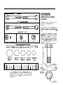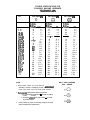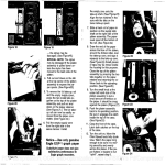
1
OPERATOR’S
MANUAL
47” Two-Stage
Commercial
Snowthrower
Mfg. No. 1692243
Hitch
Mfg. No. 1692244
STANDARD
FASTENER
IDENTIFICATION
CHART
HEX CAPSCREW
CARRIAGE
0
PLAIN WASHER
If a washer or nut is identified as
“washer, i/2” or “nut, i/2”, this
means the inside diameter is l/2
inch
BOLT
@
@
Hardware sizes given in the
illustrations throughout this
manual.
@
LOCKWASHER
NUT
If a screw is identified as “screw,
i/2 x 2”. this means the shaft
diameter is l/2 inch and the
shaft of the screw is 2 inches
long. If a screw is identified as
“screw, i/2 - 16 x 2”, the number
“16” means that the screw has
16 threads per inch.
SAMPLE:
SCREW
IDENTIFICATION
HEX CAPSCREW IDENTlFlCATlON
Shown below are actual size heads for standard screw sizes.
Example: a l/4 screw has 7/16 head and thus requires a 7/16
wrench. To measure length, use the scale below.
00000
3lV Head
screw with
l/2” SD.
5/s” Head
screw with
7ll6’S.D.
9/16” Head
screw with
318” SD.
l/2” Head
screw with
5/16” SD.
7/l 6” Head
screw with
114” S.D.
SAMPLE: NUT IDENTIFICATION
WASHER
AND
NUT
IDENTIFICATION
Place the washer or nut on the above scale to
determine the inside diameter. The actual inside
diameter can vary 1116 inch. Use the scale for
comparison.
Nut, l/2
Inside
Diameter
TORQUE SPECIFICATIONS FOR
STANDARD MACHINE HARDWARE
SEE
SAE GRADE #2
0
9118-12
9118-18
518-I 1
518-18
314-I 0
314-I 8
718-9
718-I 4
l-8
l-12
N m .
19
20
27
31
66
78
11
12
20
2.1
2.3
3.1
3.5
7.8
8.8
15.
18.3
27.2
31.3
40.8
47.8
88.
74.8
88.4
102.
122.4
138.
217.8
244.8
190.4
210.8
299.2
328.4
30.
35
50
55
85
75
90
100
180
180
140
155
220
240
Q
In./Lbs.
FtJLbs.
23.
SAE GRADE 88
Q
InJLbs.
8-32
8-38
lo-24
lo-32
114-20
114-28
5118-18
5118-24
318-18
318-24
7/18-14
7/16-20
l/2-13
l/2-20
SAE GRADE #S
FtAbs.
30
31
43
49
8
10
17
19
30
35
50
55
75
90
110
120
150
180
280
300
400
440
580
840
NOTE:
1. These torque values are to be used for all “araware
excluding: locknuts, self-tapping screws, thread forming
screws, sheet metal screws and socket head setscrews.
2.
Recomended seating torque values for locknuts:
a. For prevailing torqix locknuts - use 65% of grade 5
torques.
b. For flange whizlock nuts (and screws) - use 135%
of grade 5 torques.
3.
Unless otherwise noted on assembly drawings all torque
values must meet this specification.
In.1Lb.s.
Nm.
3.4
3.5
4.9
5.5
10.9
13.8
23.1
25.8
40.8
47.8
88.
74.8
102.
122.4
149.8
183.2
204.
244.8
353.8
408.
544.
598.4
788.8
870.4
FtJLbs.
41
43
80
68
12
14
25
25
45
50
70
80
110
120
150
170
220
240
388
420
800
880
900
1,000
Nm.
4.8
4.9
8.8
7.7
18.3
19.
34.
34.
81.2
68.
95.2
108.8
149.8
183.2
204.
231.2
299.2
328.4
525.
571.2
818.
897.6
1,224.
1.360.
BOLT HEAD MARKING
S.A.E. GRADE:
SIMPLICITY MANUFACTURING,
500 N. Spring Street
Port Washington, Wi 53074
INC.
FORM 1709320
PRINTED IN U.S.A.
l/95
TABLE OF CONTENTS
SECTION
PAGE
Safety Rules
Safe Operation Practices and Precautions ..................................................................................................... 3
Safe Operation of Snowthrower.. ................................................................................................................... .3
Safe Maintenance & Storage.. ............................................ . .......................................................................... .3
Safely Transporting t h e Snowthrower.. .......................................................................................................... .3
Safety Decals ............................................................................................................................................................. 4
Parts Identification .................................................................................................................................................... 5
installation
Preparation ........................................................................................................................................ 6
Tractor
Flow Reduction Washer ................................................................................................................................. 6
C h u t e Rotator Bracket .................................................................................................................................... 6
Lift Rod ........................................................................................................................................................... 7
Install Discharge C h u t e ............. ,:. ................................................................................................................... 7
!, i
Mounting Hitch .......... . ... /. ............................................................................................................................... 8
Install PTO Driveshaft ..................................................................................................................................... 8
Mounting Snowthrower.. ................................................................................................................................. 9
Checks Prior to Using Snowthrower
Skid Shoe Adjustment .................................................................................................................................. 10
Discharge Spout Adjustment ........................................................................................................................ 1 1
Transport Height Adjustment ....................................................................................................................... .l 1
Snowthrower
Removal ............................................................................................................................................ 1 2
Hitch Removal ......................................................................................................................................................... 1 2
Using Snowthrower ................................................................................................................................................. 1 2
Maintenance & Storage Requirements
Maintenance.. ............................................................................................................................................... 1 3
Inspecting Cutting Edge ............................................................................................................................... 1 4
Reversing Cutting Edge.. .............................................................................................................................. 1 4
Shear Bolts.. ................................................................................................................................................. 1 4
Storage .................................... .................................................................................................................... 1 4
Troubleshooting
Chart ............................................................................................................................................ 15
Drift Cutter Kit, Mfg. No. 1665169.. ......................................................................................................................... 1 6
Specifications .......................................................................................................................................................... 1 6
1
SAFETY RULES
21. Disengage power to attachments when transporting or
not in use.
Safe Operation Practices and Precautions
22. Take all possible precautions when leaving the vehicle
unattended, such as disengaging the power take-off,
lowering the attachments, setting the parking brake,
stopping the engine, and removing the key.
23. Do not stop or start suddenly when going uphill or
downhill. Operate equipment up and down the face of
steep slopes; never across the face.
Product knowledge and careful operation is the best way
to prevent accidents. Read this section carefully before
operating attachment system. All operators, no matter
how much experience they may have, should read this
and other related manuals before operating attachment
system. It is the owner’s legal obligation to instruct all
operators in safe operation.
1. Know the controls and how to stop quickly. READ
THIS OPERATORS MANUAL and instructions
furnished with your tractor..
24. Reduce speed and exercise extreme caution on
slopes and in sharp turns to prevent tipping or loss of
control. Be especially cautious when changing
direction on slopes.
25. Stay alert for holes, rocks and roots in the terrain and
other hidden hazards. Keep away from drop-offs.
2. Know your equipment and its limitations.
3. Never allow children to operate equipment. Never
allow adults to operate equipment without proper
instruction.
4. Keep the area of operation clear of all persons,
particularly small children, and pets.
26. Watch out for traffic when crossing or near roadways.
27. When using any attachments, never direct discharge
of material toward bystanders nor allow anyone near
the vehicle while in operation.
28. Keep the vehicle and attachments in good operating
condition, and keep safety devices in place and in
working condition.
5. Become familiar with all controls of equipment and
how to stop tractor/engine quickly.
6. Pay special attention to, and observe all warning,
caution and danger labels on attachmentsystem.
8. Driver should never leave operator’s seat while
equipment is running.
29. Keep all nuts, bolts, and screws tight to be sure the
equipment is in safe working condition.
30. The tractor and attachments should be stopped and
inspected for damage after striking a foreign object,
and the damage should be repaired before restarting
and operating the equipment.
9. Remove objects (sticks, stones and any other debris)
from area of operation that may be picked up and
thrown.
Safe Operation of Snowthrower
7. Do not allow passengers on tractor or attachment
system at any time.
IO. Operate equipment only during daylight or with
adequate artificial light.
il. Wear long pants and safe, sturdy shoes. Do not wear
loose fitting clothing that could get caught in moving
parts.
1. Inspect snowthrower carefully for loose or worn parts
before operating.
12. Always wear eye protection (safety glasses, fSCS
shield, safety goggles, etc.) to protect from any flying
objects and ear protection (ear muffs, ear plug, etc.) to
protect from excessive noise.
3. Disengage PTO and shift into neutral before starting
the engine (motor).
4. Do not operate the equipment without wearing
adequate winter outer garments. Wear footwear that
will improve footing on slippery surfaces.
2. Thoroughly inspect the area where the equipment is
to be used and remove all doormats, sleds, boards,
wires, and other foreign objects.
13. Only operate equipment when fully alert. Therefore,
never operate equipment while fatigued, under the
influence of alcohol, medication or other substances.
5. Before dismounting the tractor:
a. Disengage power takeoff (PTO).
14. Know how to stop engine. Be prepared for an emergency situation.
b. Shut off engine.
c. Allow all moving parts to stop.
15. Avoid high pressure fluids. Escaping fluid under
pressure can cause serious injury.
d. Set parking brake.
e. Remove key.
6. Handle fuel with care; it is highly flammable.
16. Never attempt to make adjustment or repair of any
kind while the tractor and/or attachments are in
motion. Shut off engine, remove key and allow all
motion to stop.
a. Use an approved fuel container.
b. Never add fuel to a running or hot engine.
c. Fill fuel tank outdoors with extreme care. Never fill
fuel tank indoors.
17. Open doors if tractor engine is run in garage or shed
-exhaust fumes are dangerous.
18. Follow the maintenance recommendations for Safe
operation. See “Maintenance” section.
19. Disengage all attachment clutches and shift into
neutral before attempting to start the engine.
d. Replace gasoline cap securely and wipe up spilled
fuel.
7. Adjust the snowthrower housing height to clear gravel
or crushed rock surface.
20. Disengage power to attachments and stop the engine
before leaving the operator’s position.
2
8. Never attempt to make any adjustments while the
engine is running (except when specifically recommended by manufacturer).
Do not attempt to clear steep slopes.
22. Never operate the snowthrower without proper
guards, plates, or other safety protective devices in
place.
23. Never operate the snowthrower near glass enclosures, automobiles, window wells, drop-offs, and the
like without proper adjustment of the snow discharge
angle. Keep children and pets away.
24. Do not overload the machine capacity by attempting
to clear snow at too fast a rate.
9. Let engine (motor) and machine adjust to outdoor
temperatures before starting to clear snow.
10. Always wear safety glasses or eye shields during
operation or while performing an adjustment or repair
to protect eyes from foreign objects that may be
thrown from the machine.
Il. Cross gravel driveways, sidewalks, or roads with
extreme caution. Loose sand and rocks may be
picked up and thrown. Before operating, adjust height
of skid shoes (if equipped) to clear gravel or crushed
rock surfaces.
25. Never operate the machine at high transport speeds
on slippery surfaces. Use care when backing.
26. Never direct discharge at bystanders or allow anyone
in front of the unit.
12. If discharge chute becomes clogged, stop tractor,
disengage power take-off (PTO) by pulling PTO
switch downward, shut off engine, remove key and
after all moving parts have stopped, clean out discharge chute.
27. Disengage power to the collector/impeller when the
snowthrower is transported or not in use.
28. Use only attachments and accessories approved by
the manufacturer of the snowthrower (such as wheel
weights, counterweights, cabs, and the like).
13. Never direct discharge chute toward people, especially children, pets, or breakable objects (windows,
shrubs, vehicles, etc.) or allow anyone in front of unit.
29. Never operate the snowthrower without good visibility
or light.
14. While snowthrower is in motion, keep hands, face,
hair, clothing, etc. away from all moving parts (auger,
discharge fan, discharge chute, PTD shaft).
Safe Maintenance and Storage
1. Check shear bolts, engine mounting bolts, and other
bolts at frequent intervals for proper tightness to be
sure the equipment is in safe working condition.
15. After striking a foreign object,‘stop the engine, remove
the wire from the spark plug, thoroughly inspect the
snowthrower for any damage, and repair the damage
before restarting and operating the snow thrower.
2. Never store the tractor with fuel in the fuel tank inside
a building where ignition sources are present such as
hot water and space heaters, clothes dryers, and the
like. Allow the engine to cool before storing in any
enclosure.
16. If the unit should start to vibrate abnormally, stop the
engine and check immediately for the cause. Vibration
is generally a warning of trouble.
17. Stop the engine whenever you leave the operating
position, before unclogging the collector/impeller
housing or discharge guide, and when making any
repairs, adjustments, or inspections.
3. Always refer to Operator’s Manual for important
details if the snowthrower is to be stored for an
extended period.
4. Maintain or replace safety and instruction labels, as
necessary.
18. Take all possible precautions when leaving the
machines unattended. Disengage the power takeoff,
lower the attachment, set the parking brake, stop the
engine, and remove the key.
5. Run the machine a few minutes after blowing snow to
prevent freeze-up of the collector/impeller.
19. When cleaning, repairing, or inspecting, make certain
the collector/impeller and all moving parts have
stopped. Disconnect the spark plug wire and keep the
wire away from the plug to prevent accidental starting.
Safely Transporting the Snowthrower
1. Always use a heavy-duty trailer to transport equipment, whether or not attachment system is mounted
to tractor.
20. Do not run the engine indoors, except when starting
the engine and for transporting the snowthrower in or
out of the building. Open the outside doors; exhaust
fumes are dangerous.
2. Be sure trailer has all necessary lights and signs
required by local, state, provincial or federal laws.
3. Make sure all equipment is securely fastened to trailer
with straps, chains, cables, etc.
21. Do not clear snow across the face of slopes. Exercise
extreme caution when changing direction on slopes.
3
SAFETY DECALS
The following safety labels are located on your tractor as
shown.
TO PREVENT SERIOUS INJURY, CAREFULLY READ
AND FOLLOW THESE WARNING INSTRUCTIONS AT
AU TIMES.
THIS DECAL MUST
BE POSITIONED SO AS TO
BE EASILY READ FROM
THE FRONT OF THE
SNOWTHROWER
PARTS IDENTIFICATION
TOOLS NECESSARY FOR INSTALLATION
AND ASSEMBLY:
One (1) l/2” Wrench
Two (2) 7/l 6” Wrench
One (1) 3/i&’ Allen Wrench
Note: Right and left hand sides are determined by
facing forward in the tractor seat.
AUGER
SHEAR
BOLT
LEVEL CHECK PLUG
CUTTING EDGE
AUGER
SUPPORT
SPRING
REDUCTION
GEARBOX
SKID SHOE
PIN
5
SHEAR BOLT
INSTALLATION
Tractor Preparation
1. Increase the front tire pressure to 20 PSI for use with
snowthrower.
2. On tractors with Kohler Magnum engines, loosen the
air cleaner cover wing nut, pull intake hose out of
plenum hole and rotate cover slightly. For winter
operation only, this allows warmer air to be taken in
through the air cleaner. This is not necessary for
Kohler Command engines.
Flow Reduction Washer
A washer is provided which must be added to the hydraulic valve. The purpose of the washer is to increase travel
time when the snowthrower is lowered. This washer has
an i/2’ O.D. and a hole in the middle slightly smaller than
i/16” I.D.
1. Remove the upper left-hand panel from the tractor to
expose the valve (A, figure 1).
2. Notice there are two elbows on the side. Disconnect
the hose (B) from the front elbow (C). Remove the
elbow.
3. Place the washer so it is fully seated inthe hole.
Figure 1. Flow Reduction Washer
A. Valve
8. Hose
C. Front Elbow
4: Reinstall the elbow (C) and then connect the hose (B).
Tighten the nut securely after elbow is properly
positioned.
Note: Flow reduction washer can be left installed in
hydraulic valve for use with mower and other
attachments.
Chute Rotator Bracket
Install the chute rotator bracket (A, figure 2) as follows:
1. Remove top front capscrew (B), lo&washer, and nut
from the tractor. Retain hardware for reassembly.
2. Remove the bottom bolt (C) and discard. Retain the
flange nut for reassembly.
3. Insert the bracket (A) between the tractor frame and
footrest. Secure with existing hardware in the top front
location, At the bottom hole, install 3/8-16x i-1/2”
capscrew and flat washer from outside the frame, with
a second flat washer placed between the rotator
bracket and footrest bracket. Capscrew and flat
washers are supplied in kit hardware bag. Secure with
the existing flange nut.
4. Tighten all hardware.
Chute Rotator Bracket
Top Capscrew
C. Bottom Capscrew
6
Lift Rod
1. Lay lift rod (A, figure 3) next to the tractor so that rear
clevis (B) with square weldment (C) is towards the
rear. The weldment is positioned to prevent clevis pin
(D) from being installed from the right hand side
(interference would occur).
2. The lift rod must be inserted from the rear of the front
axle, aligning rear clews (B) with the tractor lift lever
(F). Install clews pin (D) from inside and secure and
spring clip (E).
Figure 3. Installing Lift Rod
A. Lift Rod
D. Clevis Pin
B. Rear Clews
E. Spring Clip
C. Square Weldment
F. Tractor Lift Lever
Install Discharge Chute
1. Install nylon ring (A, figure 4) over snowthrower
bottom discharge opening.
2. Install chute underneath left rear retaining bracket (B,
factory installed). Make sure that chute ring gear teeth
mesh with spiral rotator spring. The PTO retaining
hook(F) should be pre-installed in the outside hole of
the left rear bracket, if not, install it using l/4-20” nut.
3. Install three other chute retaining brackets (B) and
secure with 1/4-20x 3/4” capscrews (C), lo&washers
(D) and i/4-20 nuts (E).
4. Tighten hardware securely with two 7/16” wrenches.
Figure 4. Installing Spout
A. Nylon Ring
8. Chute Retaining Bracket
C. Capscrew
D. Lockwasher
E. Nut
F. PTO Retaining Hook
7
Mounting Hitch
1. Park tractor on a hard level surface.
2. Stop engine, lock parking brake, and remove key.
3. Place hitch on ground in front of tractor with pivot plate
facing away from tractor.
4. Rotate the hitch attaching links rearward toward the
tractor.
5. Install the back of hitch so that hitch pins (A, figure 5)
are cradled in tractor hitch bracket (B). The lift rod
front clevis must be positioned over the hitch lift arm
while raising hitch into position.
6. From inside hitch, install the left and right clevis pins
(C)through attaching links and tractor hitch bracket
(B). Secure with spring clips (D).
Figure 5. Mounting Hitch
A. Hitch Pins
B. Tractor Hitch Bracket
C. Clevis Pin
D. Spring Clip (Hitch)
E. Clevis Pin
7. Align the holes in the lift rod front clevis and tractor lift
arm (may have to lift up on front hitch slightly). To
avoid interference, install the clevis pin (E) from inside
(flat head towards PTO belts). Secure the clevis pin
with spring clip on outside of lift arm clevis.
8. Check the “Transport Height Adjustment” procedure
on page 11 before snowthrower is installed.
Install PTO Driveshafl
1. Install l/4” x 1” square key in keyway.
2. Install driveshaft
(A, figure 6) with setscrew over key.
3. Secure the driveshaft with l/4-20 x 1 7/8”capscrew
(Grade 5) and i/4-20 locknut at location B.
NOTE: 1/4-20x l-7/8 capscrew supplied in kit hardware bag has been ground to exact/y l-7/8 length for
use in this step.
4. Rotate the PTO driveshaft and check clearance with
the flat bearing boss just underneath. Peen end of
capscrew to prevent locknut from backing off.
5. Tighten the setscrew over key with 3/16” allen wrench.
6. Release the PTO support rod (C) from retaining hook
(D) and support driveshaft with rod.
Figure 6. Installing PTO Drvieshaft
(Snowthrower Side)
A. Driveshaft
B. Capscrew Location
C. PTO Support Rod
D. Retaining Hook
(Note: Hydraulic chute rotator model shown in photo.)
8
Mounting Snowthrower
Note: The auger blades are shipped in identical position
for shipping purposes. Remove either left or right hand
shear bolt (refer to figure 18 on page 14) then turn one
auger 180” and reinstall shear bolt.
MAKE SURE PIVOT
PLATE IS SEATED
1. Park tractor on hard level surface.
2. Stop engine, lock parking brake and remove key.
3. Place snowthrower’s shot pins (A, figure 7) in
released position (shot pins shown in figure 7 are in
locked position).
4. Make sure that PTO shaft is held in supporting rod.
This is done to prevent PTO shaft from interfering with
connection point and to help align the shaft for
hookup.
5. See figure 8. Check that pivot plate is locked into
straight forward position. Do not use any of the angle
positions with the snowthrower. To lock pivot plate,
push pin (A) down and turn until roll pin (B) fits
securely into groove.
Figure 7. Mounting Snowthrower
A. Shot Pins
B. Pivot Plate
C. Adaptor Plate
MOTE: An/e positions ofpivot plate.,aie used with
other attachments.
6. See figure 7. From the tractor seat, start tractor and
slowly drive toward snowthrower, while aligning pivot
plate (B) with back adapter plate (C) of snowthrower.
7. When tractor is approximately one foot away from
snowthrower, stop tractor and lower hitch so it is
positioned just above the ground (i/4 to i/2 inch off
the ground).
8. See figure 7. Slowly drive toward snowthrower until
pivot plate (B) makes contact with back plate (C) of
snowthrower.
9. Bring tractor to stop and slowly raise hitch until top lip
of pivot plate slides into groove of back plate and shot
pins (A) slide into place.
10. Stop engine, lock parking brake and remove key.
11. Check that snowthrower’s shot pins are fully seated
into pivot plate. If pins are not yet seated, seat pins.
Figure 8. Pivot Plate Lock
12. Return PTO support rod to retaining hook.
A. Lock Pin
B. Roll Pin
13. Attach snowthrower PTO coupling to tractor PTO
shaft.
a. Pull outer ring (A, figure 9) of PTO shaft back.
b. Slide PTO coupling onto spline shaft of tractor,
pushing coupling foward when splines are aligned.
c. Release outer ring, ensuring ring snaps forward,
locking PTO into place.
Figure 9. Installing PTO Driveshaft (Tractor Side)
A. Outer (Locking) Ring
9
14. Attach the bottom half of the spout rotator handcrank
(A, figure IO) to the spiral spring shaft (B) and secure
with large ring pin at location C.
15. Slide the upper half of spout rotator handcrank
through the retaining bracket and into the lower half of
handcrank. Secure the upper half just in front of
retaining bracket with the small ring pin to prevent
movement of the handcrank.
16. The snowthrower is now ready for operation,
Figure 16. Attaching Handcrank
A. Spout Rotator (Bottom Half)
B. Spiral Spring Shaft
C. Large Ring Pin Location
CHECKS PRIOR TO USING
S N O W T H R O W E R ., ‘1
1.’ Read safety precautions on pages 2-3 of this manual.
2. Prior to any snow falling, survey area to make sure
that all objects are removed to prevent them from
being picked up and thrown from the snowthrower
resulting in personal injury or property damage.
3. Make sure PTO shield turns freely on PTO shaft and
guards are properly fastened.
4. Make sure oil level in auger gearbox and speed
reduction gearbox is correct (oil level should be even
with check plugs). Refer to figures 14 & 15 on page
13.
5. Inspect for loose, missing, and worn parts.
6. Properly adjust discharge chute, discharge spout and
skid shoes. Refer to following paragraphs and figures
11 and 12.
7. Adjust the transport height if necessary. Refer to
“Transport Height Adjustment” on page 11.
Skid Shoe Adjustment
NOTE: This procedure applies to both side and rear skid
shoes.Side skid shoes are optional equipment and must
be purchased separately under kit number 1713411.
1. Using a l/2” wrench, loosen both nuts.
2. Adjust to desired height.
Figure 11. Skid Shoe Adjustment
3. Tighten nuts.
10
A
WARNING:
Before operating snowthrower, make sure to
position discharge chute away from people, pets,
windows or other property which may be injured or
damaged by snow or other thrown objects.
Discharge Spout Adjustment
The spout can be adjusted by loosening the knob on the
left hand side and rotating spout up or down. Adjust the
spout for desired throwing distance and snow conditions
(depth and wetness).
I
I
Figure 12. Adjusting Discharge Spout
Transport Height Adjustment
A
WARNING
Always &top the engine and before inspecting
snowthrower or making adjustments.
1. Start the tractor engine. Using the tractor lift lever,
raise the snowthrower to highest position. There
should be a slight clearance between back of hitch
and tractor stops. This will prevent the hydraulic
pump from working against stops when snowthrower
is fully raised.To check, raise up on snowthrower hitch
by hand. You should be able to raise up on the hitch
one to two inches before upward movement is
stopped by tractor.
2. See figure 13. To adjust, loosen the two nuts (A)
using a i-1/8” open-end wrench. Using a 15/16”
socket, turn the two bolts (B) in or out an equal
amount until adjustment is correct. Turning bolts in
will raise the snowthrower - turning bolts out will lower
snowthrower. Tighten the two nuts (A) when adjustment is correct.
6
3. Make sure that hitch cannot be lifted to a height
where the PTO driveshaft can contact the bottom of
the tractor hood.
Figure 13. Transport Height Adjustment
A. Nuts
B. Adjustment Bolts
11
SNOWTHROWER REMOVAL
USING SNOWTHROWER
I
Refer to figures 6-10 on pages 8-10 for removal procedures.
1. Park tractor on hard level surface.
2. Lower snowthrower attachment to ground.
A
CAUTION
Start snowthrower with engine running slowly to
prevent damage to snowthrower and tractor.
3. Stop engine, lock parking brake, and remove key.
1. Run engine at one quarter throttle.
4. Pull coupler (A, figure 9) on snowthrower PTO shaft
and disconnect from tractor’s PTO shaft.
2. Engage PTO switch to start snowthrower.
5. Remove PTO support rod (C, figure 6) from retaining
hook (D) and support PTO driveshaft (A).
3. Run engine at full throttle.
4. Lower snowthrower to ground and slowly drive into
area to be cleared.
6. See figure 10. Remove large ring pin C) securing
bottom half of handcrank from spiral spring shaft (B)
and remove handcrank.
A
7. Remove small ring pin holding upper half of
handcrank in bracket and remove handcrank.
CAUTION
When operating snowthrower, do not use downward pressure, in order to avoid damage to cutting
edge and snowthrower.
Note: Chute Rotator Bracket (refer to figure 2, page 6)
can be left installed or removed for operation of other
attachments.
8. Pull out shot pins (A, figure 7) on rear of snowthrower
and turn until roll pin fits in groove. Repeat for other
s i d e .
5. Disengage PTO switch to stop snowthrower.
A
9. Start tractor, lower hitch, and slowly backaway from
snowthrower.
Note: Leave PTO driveshaft mounied on snowthrower
suppotied by PTO support rod.
WARNING
If any object is picked up and/or thrown, other than
snow, stop snowthrower and tractor (stop engine,
lock parking brake and remove key) immediately
and inspect for damage.
IO. Store snowthrower with PTO, handcrank and chute
rotator bracket (if removed).
HITCH REMOVAL
Refer to figure 3, page 7 and figure 5, page 8 for hitch
removal procedures.
1. Park tractor on hard level surface.
2. Stop engine, lock parking brake, and remove key.
3. Remove spring clip and clevis pin (E, figure 5) securing lift rod front clevis to hitch lift arm.
4. See figure 3. Remove spring clip (E) and clevis pin
(D), securing lift rod rear clevis (B) to tractor lift lever
(F). Remove lift rod (A).
5. See figure 5. Remove left and right spring clips (D)
and clevis pins (C) securing attaching links to tractor
hitch.
6. See figure 5. Raise hitch and pull foward to remove
hitch pins (A) from tractor hitch brackets(B).
7. Remove and store hitch with lift arm and attaching
hardware.
12
I
MAINTENANCE & STORAGE
REQUIREMENTS
I
A
WARNING
Only perform maintenance inspections and procedures with tractor parked on hard, level surface;
PTO disengaged; engine stopped; parking brake
locked and key removed.
Maintenance
1. Frequently check for loose or worn parts.
2. Check auger gearbox oil level every 25 hours:
a. Park tractor on level surface.
b. Lower snowthrower.
c. Stop engine, lock parking brake, and remove key.
d. Remove check plug (A, figure 14).
e. Level of oil should be even with check plug. If low,
remove fill plug (B, figure 14), add Shell Omala 460
Gear Oil.
f . Install and tighten both check andf.ill plugs.
3. Periodically lubricate the grease fittings located on
both knuckles of the PTO shaft and the grease fitting
(C, figure 14) on each end of the auger.
4. Periodically check PTO belt for proper tension and
excessive wear. If belt needs tightening or replacement, refer to the tractor Owners Manual.
5. Snowthrower is equipped with a cutting edge which
can be reversed when one side is worn. Refer to
figure 16 on next page.
Figure 14. Auger Gearbox
A. Check Plug
B. Fill/Vent Plug
C. Grease Fittings
6. Check the oil level in the snowthrower speed reduction gearbox every 25 hours:
a. Park tractor on level surface.
b. Lower snowthrower.
c. Stop engine, lock parking brake, and remove key.
d. Remove check plug (A, figure 15).
e. Level of oil should be even with check plug. If low,
remove fill/vent plug (B, figure 15) add 30 Wt.
Motor Oil.
f . Install and tighten both check and fill plugs.
Figure 15. Speed Reduction Gearbox
A. Check Plug
B. Fill/Vent Plug
13
Inspecting Cutting Edge
1. Raise snowthrower to highest position.
2. Use safety block(s) to secure snowthrower:
a. Place safety block under attachment.
b. Lower attachment until it rests on block(s).
3. Inspect location where cutting edge (A, figure 16)
meets snowthrower housing.
Reversing Cutting Edge
1. Raise blower to highest position.
2. Use safety block(s) to secure blower.
I
a. Raise attachment to top height.
b. Place safety block under attachment.
Figure 16. Cutting Edge
A. Cutting Edge
B. Mounting Hardware
c. Lower attachment until it rests on block(s).
3. Using l/2” wrench remove six (6) nuts, washers, and
bolts (B, figure 16).
4. Remove cutting edge.
5. Reverse or replace cutting edge.
6. Replace six (6) bolts, washers, nuts and tighten.
Shear bolts
Refer to figure 17 for discharge fan shear bolt (grade 3
hardness, 5/16” x 1”).
Refer to figure 18 for auger shear bolt (one in each augerspecialized, grade 3 hardness, 5/i 6” x 2”).
1. Check for excessive wear.
2. Shear bolt will break if auger or fan hits solid object. If
this happens:
a. Stop snowthrower and tractor immediately.
b. Stop engine, lock parking brake, remove key.
c. Remove shear bolt.
d. Replace with new shear bolt. Make sure replacement shear bolt is Grade 3 hardness.
e. Locate and correct cause of shearing.
Figure 17. Discharge Fan Shear Bolt
Storage
1. Clean snowthrower.
2. Check and repair or replace worn or damaged parts.
3. Paint appropriate areas to prevent rust.
4. Lubricate all necessary parts.
5. Cover and store.
Figure 18. Auger Shear Bolt
14
TROUBLESHOOTING
A
WARNING:
Only perform maintenanceinspectionsandprocedureswithtractorparkedon
hard,level
surface; PTO disengaged, engine stopped; parking brake locked and key removed.
PROBLEM
CAUSE
CORRECTIVE
ACTION
Lock pin has not
been slid into place.
Slide lock pin into
locked position.
Broken spring on lock pin,
Replace spring.
Broken roll pin on lock pin.
Replace roll pin.
Broken lock pin.
Replace lock pin.
Blower does not
operate at all.
Drive belt on tractor PTO
loose or not attached.
Tighten or attach belt
properly.
Auger does not
Broken shear bolt.
Replace shear bolt.
rotate.
Faulty auger gearbox.
See your dealer.
Discharge fan does
Brok6n1shear
Replace shear bolt.
See your dealer.
Pivot plate will not stay
locked in one position.
bolt.
not rotate.
‘Faulty PTO shaft u-joints.
Snowthrower vibrates
excessively.
Faulty bearings (gearbox,
auger or discharge fan).
See your dealer.
Auger or discharge
fan bent or broken.
See your dealer.
Faulty auger gearbox.
See your dealer.
Faulty speed reduction
gearbox.
See your dealer.
Uneven cut on
bottom of blower.
Cutting edge is worn
back to blower
housing.
Replace or reverse
cutting edge.
Uneven cut on
bottom of blower.
Skid shoes are not
back to blower housing.
Check and adjust
shoes accordingly.
Discharge chute does
not rotate.
Discharge chute not
lubricated.
Worn plastic ring
underneath chute.
Lubricate discharge chute.
Something is caught
in discharge fan.
Inspect and remove
foreign material with
engine off and all
motion stopped.
Replace plastic ring.
15
DRIFT CUTTER KIT, MFG. NO. 1685189
Drift cutters can be installed on left and right hand side to
assist in knocking down deep snowbanks into the auger
housing. It may be necessary to drill holes for installation.
Follow instructions supplied with kit.
Figurel8. Drift Cutters
SPECIFICATIONS
Cutting width: 47”
Cutting height: 20”
Auger diameter: 13.5”
Discharge fan diameter: 16”
Drive system: PTO shafl
Estimated auger rotation speed: 180 RPM
Estimated fan rotation speed: 900 RPM
Chute rotation: 200 degrees
Snowthrower weight: 180 pounds
Hitch weight: 95 pounds.
16