1
The Chamberlain Group, Inc.
845 Larch Avenue
Elmhurst, Illinois 60126-1196
www.liftmaster.com
Radio
Receiver
Included
Mega ARM Tower
Models:
MADCBB, MATDCBB, MASDCBB & MASTDCBB
(MEGA ARM, MEGA ARM TOWER, MEGA SPRINT & MEGA SPRINT TOWER)
1/2 HP COMMERCIAL DUTY PARKING GATE OPERATOR
INSTALLATION AND SERVICE MANUAL
IMPORTANT: Read and understand Warranty Page first.
Batteries (included) MUST be connected for proper operation of unit.
Use (2) LiftMaster 12Vdc 7AH (Part # MBAT).
TA B L E O F C O N T E N T S
INTRODUCTION
OPERATION AND MAINTENANCE
Safety Symbol and Signal Word Review . . . . . . . . . . . . . . . . .3
Tools Needed For Installation . . . . . . . . . . . . . . . . . . . . . . . . .3
Unit Overview . . . . . . . . . . . . . . . . . . . . . . . . . . . . . . . . . . . . .3
Important Safety Instructions . . . . . . . . . . . . . . . . . . . . . . . .12
General Service . . . . . . . . . . . . . . . . . . . . . . . . . . . . . . . . . . .13
Shear Pin Replacement . . . . . . . . . . . . . . . . . . . . . . . . . . . . .13
Battery Disposal . . . . . . . . . . . . . . . . . . . . . . . . . . . . . . . . . . .13
Battery Replacement . . . . . . . . . . . . . . . . . . . . . . . . . . . . . . .13
Battery Maintenance/Testing . . . . . . . . . . . . . . . . . . . . . . . . .13
Battery Handling/Storage . . . . . . . . . . . . . . . . . . . . . . . . . . . .13
UL325 MODEL CLASSIFICATIONS . . . . . . . . . . . . . . . . . .4
SAFETY INSTALLATION INFORMATION . . . . . . . . . . . . .5
INSTALLATION
TROUBLESHOOTING
Concrete Pad . . . . . . . . . . . . . . . . . . . . . . . . . . . . . . . . . . . . . .6
Anchors . . . . . . . . . . . . . . . . . . . . . . . . . . . . . . . . . . . . . . . . . .6
Conduits . . . . . . . . . . . . . . . . . . . . . . . . . . . . . . . . . . . . . . . . .6
Dimensions . . . . . . . . . . . . . . . . . . . . . . . . . . . . . . . . . . . . . . .6
Battery Checkout . . . . . . . . . . . . . . . . . . . . . . . . . . . . . . . . . .14
Gate Not Operating . . . . . . . . . . . . . . . . . . . . . . . . . . . . . . . .14
Troubleshooting Chart . . . . . . . . . . . . . . . . . . . . . . . . . . . . . .14
SUGGESTED LOOP SENSOR LOCATIONS
WIRING AND HOOKUP
Free Exit Operation . . . . . . . . . . . . . . . . . . . . . . . . . . . . . . . .15
Entry With Access Control Device . . . . . . . . . . . . . . . . . . . . .15
Dual Direction . . . . . . . . . . . . . . . . . . . . . . . . . . . . . . . . . . . .15
AC Power Hookup (120/230 Vac) . . . . . . . . . . . . . . . . . . . . . .7
Input Commands 1-8 . . . . . . . . . . . . . . . . . . . . . . . . . . . . . . . .7
Accessory and Relay Connections . . . . . . . . . . . . . . . . . . . . . .8
Battery Installation . . . . . . . . . . . . . . . . . . . . . . . . . . . . . . . . . .8
Master/Second Wiring . . . . . . . . . . . . . . . . . . . . . . . . . . . . . . .8
TRAP INSTRUCTIONS . . . . . . . . . . . . . . . . . . . . . . . . . . . .16
SEQUENCE ACCESS MANAGEMENT SYSTEM (SAMS)
REVERSING ARM DIRECTION
SAMS With Other Operators . . . . . . . . . . . . . . . . . . . . . . . . .17
SAMS Two Mega Arms with “Memory” . . . . . . . . . . . . . . . . .17
Reversing the Direction of the Arm . . . . . . . . . . . . . . . . . . . . .9
TIMERS AND MODE SELECTIONS S1 & S2
CONTROL BOARD LAYOUT
Mode Selections - S1 . . . . . . . . . . . . . . . . . . . . . . . . . . . . . .10
Fast Run Timer - S1 . . . . . . . . . . . . . . . . . . . . . . . . . . . . . . .10
Close Timer Selection - S2 . . . . . . . . . . . . . . . . . . . . . . . . . .10
Mode Selections - S2 . . . . . . . . . . . . . . . . . . . . . . . . . . . . . .10
Input Locations . . . . . . . . . . . . . . . . . . . . . . . . . . . . . . . . . . .18
MEGA ARM UL PARTS LIST
Part Numbers and Descriptions . . . . . . . . . . . . . . . . . . . . . . .19
Parts Shipped . . . . . . . . . . . . . . . . . . . . . . . . . . . . . . . . . . . .19
Mega Arm Tower Unique Parts List . . . . . . . . . . . . . . . . . . . .19
Mega Arm Options Parts List . . . . . . . . . . . . . . . . . . . . . . . .19
INSTALL THE RECEIVER
Wiring the Receiver . . . . . . . . . . . . . . . . . . . . . . . . . . . . . . . .11
Set Security Mode . . . . . . . . . . . . . . . . . . . . . . . . . . . . . . . . .11
Programming the Remote to the Receiver . . . . . . . . . . . . . .11
To Erase All Remote Control Codes . . . . . . . . . . . . . . . . . . . .11
ACCESSORIES . . . . . . . . . . . . . . . . . . . . . . . . . . . . . . . . . . .20
OPERATOR NOTES . . . . . . . . . . . . . . . . . . . . . . . . . . . . .21-22
ADJUSTMENT
WARRANTY POLICY AND REGISTRATION . . . . . . . . . .23
Instant Reverse Device (IRD) . . . . . . . . . . . . . . . . . . . . . . . .12
Gate Arm Leveling . . . . . . . . . . . . . . . . . . . . . . . . . . . . . . . . .12
REPAIR PARTS AND SERVICE . . . . . . . . . . . . . . . . . . . . .24
2
INTRODUCTION
IMPORTANT NOTE
WARNING
WARNING
• BEFORE attempting to install, operate or maintain the operator,
you must read and fully understand this manual and follow all
safety instructions.
• DO NOT attempt repair or service of your commercial door and
gate operator unless you are an Authorized Service Technician.
Mechanical
CAUTION
WARNING
WARNING
WARNING
WARNING
Electrical
WARNING
CAUTION
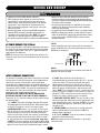
TOOLS NEEDED FOR INSTALLATION
WARNING
During assembly, installation and adjustment of the operator the
tools listed below may be needed.
• Wrench or Socket Set
• Phillips Head Screwdriver
• C Clamps
• Level
• Small Screwdriver
• T25 Torx Head Screwdriver
When you see these Safety Symbols and Signal Words on the
following pages, they will alert you to the possibility of serious
injury or death if you do not comply with the warnings that
accompany them. The hazard may come from something
mechanical or from electric shock. Read the warnings carefully.
When you see this Signal Word on the following pages, it will
alert you to the possibility of damage to your gate and/or the gate
operator if you do not comply with the cautionary statements that
accompany it. Read them carefully.
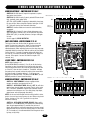
UNIT OVERVIEW
• Molded Polyethylene UV stabilized cover never needs wax or
paint (excludes towers).
• Direct drive gear reducer eliminates many parts that might
otherwise fail.
• State of the art MOSFET motor drive technology, NO contactors
or relays.
• Soft start and stop in open and close travel motions.
• No limit switches to fail - uses magnetic (Hall Effect) sensors to
monitor arm position.
• Maximum Run Timer for motor with anti-tamper protection in
closing direction.
• Each unit configurable as master or second operator.
• Safe 24 Vdc low voltage motor and control wiring.
• LED diagnostics for easy trouble shooting.
• Closing timer adjustable from 1-31 seconds with on/off
selection.
• Transient voltage protection on all inputs.
• Capable of being powered from 120 or 230 Vac, or UL Listed
Class 2 Solar Power.
• On 120 Vac installations, unswitched duplex outlet gives
convenient supply for 120 Vac accessories.
• 10 year perforation warranty on cover and chassis with 2 years
on electronics and mechanism.
NOTE: If the operator is installed in a region where temperatures
regularly go below 30˚ F then it is recommended that the optional
heater is installed. Refer to the accessory page.
The LiftMaster model MEGA ARM barrier style parking gate
operator is unique in the industry. Setting the MEGA ARM apart
are many features that make it the front runner in its class:
• Built in battery run - inherent 24 Vdc backup power with
regulated 24 Vdc for accessories.
• High torque 24 volt Permanent Magnet DC motor.
• Full service controller with eight inputs and LED indicators for
loops, card reader, radio, etc.
• Reversible arm direction for right or left handed operation.
• Instant Reverse Device (IRD) monitor senses obstructions
during motion.
• Automatic open of gate arm when power is lost if desired (with
15 sec. delay selection).
• Raise gate input memory will memorize multiple vehicles – ideal
for bar code scanners and AVI.
• Ability to STOP arm in close travel if tail-gating is sensed at
close loop.
• Anti-tail gate alarm - fires K1 relay to trigger a warning device
when tail-gating is sensed.
• SAMS with “memory” - allows Mega Arm to open a slide/swing
gate first then raises arm.
• Break away mount design for the 12-15' x 3" tubular aluminum
boom arm.
• Dynamic motor braking to preserve arm positioning.
• All rust proof aluminum construction with white powder coat
baked on enamel.
3
U L 3 2 5 M O D E L C L A S S I F I C AT I O N S
CLASS I – RESIDENTIAL VEHICULAR GATE OPERATOR
A vehicular gate operator (or system) intended for use in a home of one-to four single family dwellings,
or a garage or parking area associated therewith.
CLASS II – COMMERCIAL/GENERAL ACCESS VEHICULAR GATE OPERATOR
A vehicular gate operator (or system) intended for use in a commercial location or building such as a
multi-family housing unit (five or more single family units) hotel, garage, retail store or other building
servicing the general public.
CLASS III – INDUSTRIAL/LIMITED ACCESS VEHICULAR GATE OPERATOR
A vehicular gate operator (or system) intended for use in a industrial location or building such as a
factory or loading dock area or other location not intended to service the general public.
CLASS IV – RESTRICTED ACCESS VEHICULAR GATE OPERATOR
A vehicular gate operator (or system) intended for use in a guarded industrial location or building such
as an airport security area or other restricted access locations not servicing the general public, in which
unauthorized access is prevented via supervision by security personnel.
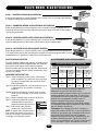
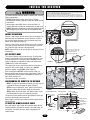
UL325 ENTRAPMENT PROTECTION REQUIREMENTS
SAFETY ACCESSORY SELECTION
All UL325 compliant LiftMaster gate operators will accept external
entrapment protection devices to protect people from motorized
gate systems. UL325 requires that the type of entrapment
protection correctly matches each gate application. Below are the
six types of entrapment protection systems recognized by UL325
for use on this operator.
GATE OPERATOR ENTRAPMENT PROTECTION
UL325
Installation
Class
ENTRAPMENT PROTECTION TYPES
Type A: Inherent obstruction sensing system, self-contained
within the operator. This system must sense and initiate
the reverse of the gate within two seconds of contact
with a solid object.
Type B1: Connections provided for a non-contact device, such as
a photoelectric eye can be used as a secondary
protection.
Type B2: Connections provided for a contact sensor. A contact
device such as a gate edge can be used for secondary
protection.
Type C: Inherent adjustable clutch or pressure relief valve.
Type D: Connections provided for a control
requiring continuous pressure to
operate the operator open and close.
Type E: Built-in audio alarm. Examples
include sirens, horns or buzzers.
Moving Gate Can Cause
Injury or Death
NOTE: UL requires that all installations must
KEEP CLEAR! Gate may move at any
time without prior warning.
have warning signs placed in plain view on
Do not let children operate the gate or
play in the gate area.
both sides of the gate to warn pedestrians of This
entrance is for vehicles only.
Pedestrians must use separate entrance
the dangers of motorized gate systems.
Slide Gate Operator
Swing & Gate Barrier
(Arm) Operator
Primary
Type
Secondary
Type
Primary
Type
Secondary
Type
Class
I & II
A
B1, B2
or D
A or C
A, B1, B2,
or C
Class III
A, B1 or
B2
A, B1, B2,
D or E
A, B1, B2
or C
A, B1, B2,
C, D or E
Class IV
A, B1, B2
or D
A, B1, B2,
D or E
A, B1, B2,
C or D
A, B1, B2,
C, D or E
The chart above illustrates the entrapment protection
requirements for each of the four UL325 classes.
In order to complete a proper installation you must satisfy the
entrapment protection chart shown above. That means that
the installation must have one primary means of entrapment
protection and one independent secondary means of
entrapment protection. Both primary and secondary
entrapment protection methods must be designed, arranged
or configured to protect against entrapments in both the open
and close directions of gate travel.
For Example: For a slide gate system that is installed on a
single-family residence (UL325 Class I) you must provide the
following: As your primary type of entrapment protection you
must provide Type A inherent (built into the operator)
entrapment sensing and at least one of the following as your
secondary entrapment protection: Type B1- Non-contact
sensors such as photoelectric eyes, Type B2- Contact sensors
such as gate edges or Type D- Constant pressure control.
4
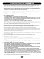
S A F E T Y I N S TA L L AT I O N I N F O R M AT I O N
1. Vehicular gate systems provide convenience and security. Gate systems are comprised of many component parts. The gate
operator is only one component. Each gate system is specifically designed for an individual application.
2. Gate operating system designers, installers and users must take into account the possible hazards associated with each individual
application. Improperly designed, installed or maintained systems can create risks for the user as well as the bystander. Gate
systems design and installation must reduce public exposure to potential hazards.
3. A gate operator can create high levels of force in its function as a component part of a gate system. Therefore, safety features
must be incorporated into every design. Specific safety features include:
• Gate Edges
• Guards for Exposed Rollers
• Photoelectric Sensors
• Screen Mesh
• Vertical Posts
• Instructional and Precautionary Signage
4. Install the gate operator only when:
a. The operator is appropriate for the construction and the usage class of the gate.
b. All openings of a horizontal slide gate are guarded or screened from the bottom of the gate to a minimum of 4' (1.2 m) above
the ground to prevent a 2 1/4" (6 cm) diameter sphere from passing through the openings anywhere in the gate, and in that
portion of the adjacent fence that the gate covers in the open position.
c. All exposed pinch points are eliminated or guarded, and guarding is supplied for exposed rollers.
5. The operator is intended for installation only on gates used for vehicles. Pedestrians must be supplied with a separate access
opening. The pedestrian access opening shall be designed to promote pedestrian usage. Locate the gate such that persons will not
come in contact with the vehicular gate during the entire path of travel of the vehicular gate.
6. The gate must be installed in a location so that enough clearance is supplied between the gate and adjacent structures when
opening and closing to reduce the risk of entrapment. Swinging gates shall not open into public access areas.
7. The gate must be properly installed and work freely in both directions prior to the installation of the gate operator.
8 Controls intended for user activation must be located at least six feet (6') away from any moving part of the gate and where the
user is prevented from reaching over, under, around or through the gate to operate the controls. Outdoor or easily accessible
controls shall have a security feature to prevent unauthorized use.
9. The Stop and/or Reset (if provided separately) must be located in the line-of-sight of the gate. Activation of the reset control shall
not cause the operator to start.
10. A minimum of two (2) WARNING SIGNS shall be installed, one on each side of the gate where easily visible.
11. For a gate operator utilizing a non-contact sensor:
a. Reference owner’s manual regarding placement of non-contact sensor for each type of application.
b. Care shall be exercised to reduce the risk of nuisance tripping, such as when a vehicle trips the sensor while the gate is still
moving.
c. One or more non-contact sensors shall be located where the risk of entrapment or obstruction exists, such as the perimeter
reachable by a moving gate or barrier.
12. For a gate operator utilizing a contact sensor such as an edge sensor:
a. One or more contact sensors shall be located where the risk of entrapment or obstruction exists, such as at the leading edge,
trailing edge and post mounted both inside and outside of a vehicular horizontal slide gate.
b. One or more contact sensors shall be located at the bottom edge of a vehicular vertical lift gate.
c. A hard wired contact sensor shall be located and its wiring arranged so the communication between the sensor and the gate
operator is not subject to mechanical damage.
d. A wireless contact sensor such as the one that transmits radio frequency (RF) signals to the gate operator for entrapment
protection functions shall be located where the transmission of the signals are not obstructed or impeded by building structures,
natural landscaping or similar obstruction. A wireless contact sensor shall function under the intended end-use conditions.
e. One or more contact sensors shall be located on the inside and outside leading edge of a swing gate. Additionally, if the bottom
edge of a swing gate is greater than 6" (152 mm) above the ground at any point in its arc of travel, one or more contact sensors
shall be located on the bottom edge.
f. One or more contact sensors shall be located at the bottom edge of a vertical barrier (arm).
5
I N S TA L L AT I O N
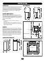
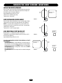
CONCRETE PAD
UNIT DIMENSIONS
3 1/2"
The concrete pad for operator mounting should be approximately
24"x24"x24" in order to provide adequate weight and structure to
insure proper and stable operation. Pad should be 6" above
finished grade or even with top of curb if one is present. (NOTE:
Pad should always extend below frost line in regions where
ground will freeze.)
15 3/4"
13 1/2"
20 1/4"
20 1/4"
41 1/2"
41 1/2"
ANCHORS (MOUNTING UNIT)
36 1/2"
21 1/2"
Proper anchors for fastening operator to pad will be a 1/2"x6"
wedge anchor patterned to match the mounting base of the unit.
They should be installed with approximately 1 1/4" showing above
concrete surface in order to allow for the 1/2" thick base plate as
well as washers for leveling.
NOTES:
• For automotive use only, no motorcycles, bicycles or
pedestrians.
• Heater option MUST be used if temperature is 30°or below.
• Heater option available for 120 Vac units only. See accessory
page for heater part number.
5"
4"
8"
17 1/2"
9"
Pad (24"x24")
12"
8"
5 1/2"
2"
CONDUITS
Conduits should be restricted to fit the 3 1/2"x3 1/2" opening in
pedestal base and 10 1/4" x 8 1/4" for the tower base. Location on
pad should be centered and spaced approximately 6" from edge
of pad on drive way side (in order to get the most reach out of
arm). Separate conduits to be included should be 120/230 Vac
main power, low voltage control wiring and one or two extra for
loop sensor leads. Conduit size should be limited to 1/2" when
possible to reduce crowding if more than four are needed. All
conduits must be UL approved.
3 1/2"
3 1/2"
Center Line
These Dimensions Will Center
the Operator on the Pad
9"
12"
6"
3 1/4"
Pedestal
Foot Print of Base on Pad
TOWER CABINET DIMENSIONS
13 1/2"
5 1/2" 8"
Inside Post
3 1/2"
Pad (24"x24"x24")
Gate Arm Bracket
3 1/2"
7 1/8"
7 1/8"
42"
10 1/4"
42"
36 1/2"
9 7/8"
Open Area In Base
8 1/4" For Conduit
13 1/2"
Side View
12 1/4"
14 1/4"
Door
14 1/4"
Tower
Foot Print of Base on Pad
6
13 1/2"
NING
W I R I N G WARNING
AND HOOKUP
TION
WARNING
To reduce the risk of SEVERE INJURY or DEATH:
• ANY maintenance to the operator or in the area near the
operator MUST not be performed until disconnecting the
electrical power and locking-out the power via the operator
power switch. Upon completion of maintenance the area
MUST be cleared and secured, at that time the unit may be
returned to service.
• Disconnecting power at the fuse box BEFORE proceeding.
Operator MUST be properly grounded and connected in
accordance with local electrical codes. NOTE: The operator
should be on a separate fused line of adequate capacity.
• ALL electrical connections MUST be made by a qualified individual.
• DO NOT install any wiring or attempt to run the operator
without consulting the wiring diagram. We recommend that
you Install an optional reversing edge BEFORE proceeding with
the control station installation.
• ALL power wiring should be on a dedicated circuit and well
protected. The location of the power disconnect should be
visible and clearly labeled.
• ALL power and control wiring MUST be run in separate conduit.
• BEFORE installing power wiring or control stations be sure to
follow all specifications and warnings described below. Failure
to do so may result in SEVERE INJURY to persons and/or
damage to operator.
120 Vac
Connect the BLACK wire to the incoming 120 Vac hot lead and
connect the WHITE wire to the incoming neutral lead. Connect the
GREEN wire to the ground.
AC POWER HOOKUP (120/230 Vac)
Be sure your main power is OFF before attempting to hook up the
AC power. The AC wiring should be attached to the wires exiting
the conduit or pedestal post. Only use U.L. approved 14AWG (or
larger) 600 volt insulated wire.
NOTE: Do not connect any of the AC power wires directly to the
electronic control board. Connect the batteries after the AC power
is restored.
Black
Green
120 Vac
White
Ground
Neutral
Top End of
4"x4" Tube
Pedestal Version
230 Vac
Please purchase the 120 to 230 Vac conversion kit for 230 Vac
operation. See Accessory page.
INPUT COMMANDS CONNECTIONS
6, CLOSE: When used with a vehicle detector, it is
Use common and normally open contacts from devices connected
recommended that the presence contacts (N.O. & C.) be used
to these inputs. Control wire connections at low voltage terminal
for the close input. This input will close gate after input is
strip will be at the top of the electronic control board. Make
applied and then removed. It will stop the open cycle and
connections to the appropriate points for the desired operation, see
reverse gate to close. (Example: Car crosses over close loop
Control Board Layout page 18. Wires should be UL approved 600
before arm reaches full open position- gate will reverse and
volt rated and at least 18 AWG. They are to be routed through the
close). (NOTE: The close input also acts as a safety-stop in that
upper grommet in chassis to avoid chafing. All external control
if gate is closing and a tailgater is sensed at the close input, the
devices must have normally open dry contacts.
gate WILL STOP its closing motion and not continue to close
CAUTION: DO NOT CONNECT ANY DEVICE WHICH WOULD
until the close input is removed or gate is re-opened).
DELIVER ANY VOLTAGE OF ANY KIND TO THESE TERMINALS.
7, BACK-AWAY (FREE EXIT INPUT): This input is used as a free
Terminals 9, 10, 11, 12 are the commons (0 Vdc) used to activate
exit input to open gate. When input is active, gate will open and
the following inputs:
close immediately once input is removed. (EXAMPLE: Car pulls
1, 2, 3 OPEN: These inputs will trigger gate open when pulsed
up to exit loop, gate opens; car “backs-away” from exit loop
or hold gate open with maintained contact. When released gate
and gate closes).
will close if closing timer is on or if close input is given.
8, SHADOW (SAMS): Used to monitor an auxiliary open limit
4, AUXILIARY OPEN: Same as 1, 2 and 3 with S2 switch 6 off.
switch of another operator in the same lane. SAMS with
With S2 switch 6 on, this input will memorize multiple vehicles
memory feature, see page 18.
and not allow gate to close until the final vehicle in memory
9, 10, 11,12 - COMMON: These are the commons (0 Vdc) to
crosses the close loop. Use with laser scanners or card readers
be used to activate above inputs.
and (transmitters with timed anti-pass back). With S1 switch 5
on, this input becomes a momentary pulse open, pulse close.
NOTE: Above inputs are tied to LED indicators to show input
5, SAFETY: This input is generally not used with the MEGA ARM. command activity.
If used its function is to make gate reverse and go back to the open
position if it was closing. Input is disabled when gate is closed.
7
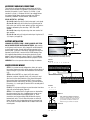
ACCESSORY AND RELAY CONNECTIONS
These terminals will provide battery backed power to 24 Vdc
devices and are located at the bottom of the electronic control
board at J4 terminals 1 and 2. Terminal 1 is 24 Vdc (+) and
number 2 is 0 Vdc (-). Peripheral CLASS 2 low voltage devices
that require 24 Vdc power maybe connected here (500 ma.
maximum). EXAMPLE: Vehicle detector, radio receiver.
RELAY OUTPUT K1 - (OPTION)
S1-6 off S1-8 off, relay will fire (latch) when gate is not closed.
S1-6 on S1-8 off, relay will fire when arm is pushed up off of
limit switch (use with slip clutch option) and fires relay when a
tail-gate is detected by the close loop - ANTI TAIL-GATE
ALARM.
S1-6 off S1-8 on, relay will pulse relay when arm reaches full
open position.
S1-6 on S1-8 on, relay will only pulse when input is given to J5
1,2,3 inputs. (see page 10).
FIGURE 1
Black Lead
–
BATTERY INSTALLATION
12 VDC Battery
HOOKING UP BATTERY LEADS - ALWAYS HOOKUP AND TURN
ON AC POWER BEFORE INSTALLING BATTERIES. After turning
on AC power, install two new, fully charged 12 volt DC batteries
on shelf next to motor. Connect red lead from operator to the
positive (RED +) terminal of one battery and black lead from the
operator to the (BLACK -) terminal of the OTHER battery. Place
the supplied jumper between the remaining terminals of each
battery if one is not already in place (Figure 1). (Use LiftMaster
MBAT or 29-NP712 for replacement batteries.) Replace in pairs.
WARNING: Do not run operator without installing the batteries.
+
Jumper
–
Red Lead
12 VDC Battery
+
Failure to install batteries correctly will cause
damage and will not be covered by warranty.
FIGURE 2
Master-J5
1
2
3
4
5
6
7
8
9 10 11 12
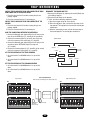
MASTER/SECOND WIRING
STEP 1: In a master/second configuration, either unit can be
the master. Choose one unit to be the master and then direct all
control wiring to it (also install vehicle detectors and receivers
in it).
STEP 2: At the MASTER, any input (at J5) with control
(detectors, receivers, keypads, timers, etc.) wires to it must
also be run to the same terminals of the second. Along with
these control wires, both operators MUST share a common
ground connection from chassis to chassis (or from common
to common, i.e., master gate J5 terminal #12 to second gate J5
terminal #12).
EXAMPLE: If only open and close are used at master then three
wires will run between gates (Figure 2).
STEP 3: If it is required that if one gate senses an obstruction,
the other reverses also, then 3 additional wires must be run
between the master J3 and second J3 (Figure 3). These
connections are for transmitting IRD (obstruction signals)
between both units. This will allow the master or second to
inform the other that a closing obstruction has occurred and
for it to reverse and open. SET switches on S2, 1-8 the same
on both gates.
Common
Close
Open
1
2
3
4
5
6
7
8
9 10 11 12
Second-J5
FIGURE 3
RX GND
1
2
3
TX
4
Master-J3
IRD - Obstruction Signal Connections
Terminal 1 of Master must go to terminal 4
of Second and terminal 1 of Second must
go to terminal 4 of Master. Terminal 2 of
Master must go to terminal 2 of Second.
Second-J3
1
2
3
RX GND
8
4
TX
REVERSING ARM DIRECTION
REVERSING THE DIRECTION OF THE ARM
The MEGA ARM allows for the “handing” or reversing of the
arm’s direction of movement in relation to the unit’s normal
operation. This allows for mounting in tight places or when it is
desired to have the arm, when across the driveway, to be in front
of the unit or behind the unit when viewed from the traffic flow
direction (Figure 1).
WARNING: POWER MUST BE OFF AND NO ARM INSTALLED
BEFORE MAKING THESE CHANGES.
STEP 1: Before power up, switch bank S1 switch #7 must be
on (Figure 1).
STEP 2: Next, the motor wires on the control board must be
reversed. At J4 on the bottom of PCB, the last 2 wires on the
right (J4-7, J4-8) normally are blue then orange. They must be
reversed to be (J4-7) orange then (J4-8) blue (Figure 2).
STEP 3: After completing the steps above, the cam arm which
adjusts the limiting points of the arm’s travel must be turned 90
degrees to the left when viewed while standing in front of the
control board (Figure 3) (cam arrow now points in the direction
of the arm and is level with mount bracket, note the small limit
sensors on the back of the PCB).
STEP 4: Now check to make sure that S1 #7 is on (Figure 1),
motor wires are reversed, the cam is adjusted, and that the
manual open/close switch (S3) is set to close. Next, turn on the
AC power and connect the batteries. Now run the gate open
and close with the S3 manual switch making sure that the
mechanism travels in the proper 90 degrees desired. Once you
are totally sure you have the correct operation, you can install
the arm
INSTALLATION NOTE: ARMS LONGER THAN 12' MUST USE THE
PROPER COUNTER WEIGHT.
FIGURE 1
S1
ON
1 2 3 4 5 6 7 8
S1, #7 to be turned ON before power up
to enable reverse of arm.
FIGURE 2
Acc+
Acc-
Battery
Black Red
Xfmr
Yellow
Motor
Blue
Orange
FIGURE 3
Cam Arm
Arm shown in reversed direction.
Output Shaft
of Gear Box
9
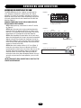
TIMERS AND MODE SELECTIONS S1 & S2
MODE SELECTIONS - SWITCH PACK S1 (5-8)
SWITCH 5: ON -Will allow J5 input #4 to operate as a pulse
open/pulse close function.
SWITCH 6: ON -Will fire relay if gate is pushed UP from closed
limit, used with clutch option. Also
ANTI TAIL-GATE ALARM, if tailgating is detected by close loop,
K1 relay will fire. When using clutch option, turning on S1-6 &
S2-7, gate will close by timer whenever forced up.
SWITCH 7: Used to enable arm to work in reverse direction,
see page 9.
SWITCH 8: Off will make K1 relay activate during open cycle
(use with buzzers, counters, etc.). On will pulse K1 relay when
OPEN LIMIT (OLS) is reached (activates a swing or slide gate
its lane).
See also page 18, RELAY OUTPUT-K1
Shows
Default
Settings
1/8ths Seconds - - 1 - - - - - 2 - - - - - 4 - - - - - - 8
S1
Switch in
OFF position
ON
OFF
OFF
OFF
OFF
OFF
OFF
OFF
OFF
1 2 3 4 5 6 7 8
Fast Run Timer 1-4
Mode Selection 5-8
7
8
CLOSE
R21
R16
R24
C3
U9
R23
X1
R1Ø
R46
U13
R5Ø
U14
R45
R49
R39
R44
R48
R43
R25
C7
X2
Q6
Q5
C6
U1Ø
DX4
R56
R6
C4
U3
R5
CPU
C5
C2Ø
+
F4
+
B1
R11
HBEAT
K1
D11
BAT LO AC POWER
D12
F3
D14
R13
BAT–
MOV
MOTOR
Aux Relay
C NC NO DC
R55
WARNING FOR
R62
CONTINUOUS
PROTECTION
AGAINST FIRE
DX1
REPLACE ONLY
WITH THE SAME
TYPE AND RATING
OF FUSE
–
J4
U19
C8
F1
D25
D26
D1
R2
R51
D2Ø
1A DC
R2Ø
R15
+
D9
Q4
D28
R3
R37
F2
R19
R4
Q1
DX2
R38
JP2
U2
D29
R57
C13
IRD
D2
TR
1
B2
J1
U16
DX3
CLS
D3
NOTE: Default setting is off.
On the MEGA ARM the switches 1-5 on S2 are for the closing
time delay to select the period of time that the gate stays open
after the obstruction sensor has reversed and re-opened the arm
or if the S2-7 timer to close is turned on. The default will keep
the gate up for 4 seconds to allow the vehicle to be moved from
the gate arm path. Changing settings 1 - 5 will increase or
decrease this hold open time. The default of 3 ON and 1, 2, 4, 5
OFF will provide a 4 second close time delay.
R59
R58
C12
U12
U7
R7
R6Ø
D27
U5
CLOSE
D4
CLOSE TIMER - SWITCH PACK S2 (1-5)
U15
R63
D21
IRD1
R8
R4Ø
R33
R43
C16
R61
R34
R26
U6
R9
BRAKE
D5
R41
U11
C22
R22
D6
T8
T7
C19
C2
OLS
D7
OPEN
T6
T5
AUX 4 SAFETY 5 CLOSE 6 BACK 7SHADOW 8
F5
C2
C1
R35
U8
U4
U1
T4
T3
OPEN 1 OPEN 2 OPEN 3
D24
6
1Ø 11 12
D23
5
9
D22
4
8
D19
3
R12
D18
2
7
R53
T2
T1
R17
1
6
R47
S3
R18
S2
8
5
R42
7
D17
6
D16
5
R36
4
D15
3
R3Ø
2
4
U18
1
3
R14
D1Ø
D8
S1
2
J5
Q2 OPEN
J3
M/S
C15
AUX LIMITS
R1
1
MANUAL
1
1
J2
The fast run timer sets the time that the operator runs at full
speed. The slow start ramp time is fixed. The slow stop ramp
time is fixed but can be overrun by the fast run time if not
adjusted properly. When adjusting make sure the slow stop ramp
completes before the close limit. With all switches off, the default
fast run time is 1.5 seconds. Changing settings will adjust fast
run timer by 1/8 second increments. (Example: #2 on equals .25
seconds, #4 on equals 1 second. #2 and #4 on equals 1.25
seconds, etc.)
C18
FAST RUN TIMER - SWITCH PACK S1 (1-4)
1
+
PWR
ACC+
ACC–
BAT–
BAT+
24VAC XFMR
MOTOR
Shows
Default
Settings
Seconds - - 1 - - - - - 2 - - - - - 4 - - - - - 8 - - - - - 16
MODE SELECTIONS - SWITCH PACK S2 (6-8)
S2
SWITCH 6 - INPUT MEMORY: Activates multiple vehicle
memory at auxiliary input terminal #4 on J5.
SWITCH 7 - AUTO CLOSE TIMER: Default is OFF. On will close
gate by timer when all inputs are cleared. Time is set by using
S2 1-5 switches. (WARNING: Special care should be used to
avoid arm from closing on cars. Use safety loops, stop loops,
photo beams and a long enough time delay.)
NOTE: Can be used with multiple vehicle memory buffer to allow
gate to close and reset count memory to zero. When using clutch
option, turning on S1-6 & S2-7, gate will close by timer
whenever forced up.
SWITCH 8 - AUTO OPEN ON POWER FAILURE: When switch
number 8 is in the ON position, the operator will automatically
open the gate approximately 15 seconds after the loss of
power. Once power is restored the operator will resume normal
operation after the first car passes closing loop or if close timer
S2-7 in turned on (it is recommended to allow the gate to close
by loop, not by timer).
ON
ON
OFF
OFF
OFF
OFF
OFF
OFF
OFF
1 2 3 4 5 6 7 8
Close Timer 1-5
10
Mode Selection 6-8
WARNING
I N S TA L L T H E R E C E I V E R
NOTICE: To comply with FCC and or Industry Canada (IC) rules, adjustment or modifications of
this receiver and/or transmitter are prohibited, except for changing the code setting or replacing
the battery. THERE ARE NO OTHER USER SERVICEABLE PARTS.
Tested to Comply with FCC Standards FOR HOME OR OFFICE USE. Operation is subject to the
following two conditions: (1) this device may not cause harmful interference, and (2) this device
must accept any interference received, including interference that may cause undesired operation.
WARNING
J5
R6Ø
DX4
C7
R56
R5
JP2
U2
R37
C5
C2Ø
+
D11
D12
F3
D14
R13
J4
U19
C NC NO DC
BAT–
R55
WARNING FOR
R62
CONTINUOUS
PROTECTION
AGAINST FIRE
DX1
REPLACE ONLY
WITH THE SAME
TYPE AND RATING
OF FUSE
MOTOR
MOV
U6
U11
U13
R34
R4Ø
R45
R49
R6Ø
R33
R39
R44
R48
R43
R59
R43
R26
BAT–
BAT+
24VAC XFMR
MOTOR
IRD1
R25
BAT–
MOV
R37
Q4
D28
F2
R15
ACC+
R2Ø
+
C5
ACC–
BAT–
1A BAT+
DC
B1
1 10
+
BAT–
2
3
4
MOTOR
MOV
–
J41
FIGURE
R13
F3
–
y
DC
D25
D26
F4
+
U19
R62
CONTINUOUS
PROTECTION
AGAINST FIRE
DX1
REPLACE ONLY
WITH THE SAME
TYPE AND RATING
OF1FUSE
C2Ø
+
BAT LO AC POWER
D14
C8
F1 J4
R11
D12
R56
P1 to J4 Accessory
Power
DX2
P2 to J4 Accessory Power
R51
P3 D2Ø
to J5 Terminal R55
1
P4 to
J5 Terminal
10
WARNING
FOR
R38
JP2
R19
HBEAT
C13
D29
CPU
1
U2
DX4
R57
C4
U3
Q6
Q5
X2
DX3
U1Ø
D14
R13
J4
U19
U16
D27
D12
C6
HBEAT
D11
U7
BAT LO AC POWER
R58
C12
U12
C7
ACC–
U5
D11
R63
D21
+
ACC+
U15
R23
B2
1
K1
U14
C16
R61
TR
1
PWR
R5Ø
R22
–
X1
Aux Relay
J1
U9
R46
C22
K1
BAT LO AC POWER
D25
D26
F4
B1
R11
HBEAT
C8
F1
+
R2
R51
D2Ø
1A DC
R2Ø
R15
+
D9
Q4
D28
R3
DX2
F2
R19
R4
D1
U8
R41
D29
R57
R38
R35
F5
C2
DX3
C13
Q1
R24
U16
R58
Q6
Q5
C6
X2
R59
R63
C12
U12
U1Ø
U15
C3
T8
T7
D24
R48
R43
R43
T6
T5
AUX 4 SAFETY 5 CLOSE 6 BACK 7SHADOW 8
D23
R49
R44
T4
T3
D27
U7
1Ø 11 12
D22
U14
R45
R39
C4
CPU
9
R53
U13
R4Ø
R6
U3
8
D19
R16
U11
R34
C22
U4
U5
R7
T2
T1
OPEN 1 OPEN 2 OPEN 3
C16
CLOSE
R21
R61
R33
CLS
D3
IRD
D2
7
R47
U9
T8
T7
R5Ø
D21
IRD1
R8
CLOSE
D4
6
D18
1Ø 11 12
R25
SET SECURITY MODE
TR
P1 - P4
1
B
The Universal Receiver can be used with up to 15 rolling code
remotes or passwords in HIGH security mode. Alternately, it can
be used with up to 31 of any type remote in NORMAL security
mode, including any combination of rolling code, billion code
(390Mhz only), or dip switch remotes.
The jumper must be set at the HIGH position for the receiver to
operate in HIGH security mode. It must be set at NORMAL
position to operate at the NORMAL mode (Figure 2).
When changing from NORMAL to HIGH security mode, any
previous remote codes must be erased. Repeat Steps 2 and 3 in
the Programming Section below to reprogram the receiver for
each remote control in use.
The receiver is factory set at HIGH.
S3
9
R42
8
R46
R26
U6
R9
C2
R41
C19
C1
R35
R23
Contacts 1 and 2 on the receiver terminal strip are for power. The
power terminals are unpolarized. Connect terminals 1 and 2 to
the accessory power terminals on the J4 terminal strip at the
bottom of the logic board (Figure 1).
Contacts 3 and 4 on the receiver terminal strip are for a common
and a relay. Connect terminals 3 and 4 to terminals 1 and 10 on
the J5 terminal strip at the top of the logic board.
NOTE: Auxiliary Pin 4 can be used for push to open/push to close
functionality.
7
T6
T5
D17
R24
R22
X1
R1Ø
6
AUX 4 SAFETY 5 CLOSE 6 BACK 7SHADOW 8
F5
C2
C2
U1
D6
5
R17
R36
7
OLS
D7
OPEN
BRAKE
D5
4
R18
T4
T3
U8
U4
R12
3
D16
6
C3
WIRING THE RECEIVER
2
OPEN 1 OPEN 2 OPEN 3
R3Ø
5
CLOSE
8R21
R16
D24
8
D15
4
7
D23
6
D22
5
D19
3
4
D18
3
R53
2
D17
1
2 R12
R47
1
R17
S2
8
D16
7
R42
6
C19
5
D15
4
R36
3
T2
T1
R3Ø
8
2
S3
R18
5
U18
7
1
R1
1
R14
U18
AVERTISSEMENT
S2
J5
Q2 OPEN
J3
M/S
D1Ø
4
R14
MANUAL
1
AUX LIMITS
C15
1
D8
3
J5
Q2 OPEN
J3
M/S
D1Ø
J2
2
C18
TS
S1
1
MANUAL
1
C15
AVERTISSEMENT
C18
To prevent possible SERIOUS INJURY or DEATH from a moving
gate or garage door:
• ALWAYS keep remote controls out of reach of children.
NEVER permit children to operate, or play with remote control
transmitters.
• Activate gate or door ONLY when it can be seen clearly, is
properly adjusted, and there are no obstructions to door travel.
• ALWAYS keep gate or garage door in sight until completely closed
NEVER permit anyone to cross path of moving gate or door.
Security Mode
Terminals
Security Mode
Terminals
Jumper
Jumper
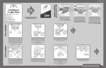
PROGRAMMING THE REMOTE TO THE RECEIVER
STEP 1: Pry open the front panel of receiver case with a coin or
a screwdriver. Re-connect power to opener (Figure 3).
STEP 2: Press and release the “learn” button on the receiver.
The learn indicator light will glow steadily for 30 seconds.
STEP 3: Within 30 seconds, press and hold the button on the
hand-held remote that you wish to operate your gate.
The opener will now operate when the push button on either the
receiver or the remote control is pressed.
Repeat Steps 2 and 3 for each remote control that will be used to
operate the gate.
NORMAL
SECURITY MODE
HIGH
SECURITY MODE
FIGURE 2
OPENING RECEIVER
Indicator Light
Learn Button
OPEN RECEIVER
TO ERASE ALL REMOTE CONTROL CODES
24V 12V
Press and hold the “learn” button on the receiver panel until the
indicator light turns off (about 6 seconds). All remote codes are
now erased. Then follow the steps above to reprogram each
remote control.
HIGH
NORM
Connect
Antenna
C
P2
M
Output Duration
Terminals
Security Mode
Power Supply
Jumper
FIGURE 3
(Not
Provided)
11
ADJUSTMENTS
INSTANT REVERSE DEVICE (IRD)
WARNING
The reverse device is an internal circuit that continuously
monitors the motors current for increased draw. Turning
the IRD1 right (CW more sensitive), or left (CCW less
sensitive) in small increments will allow sensitivity
adjustments (IF ARM DOES NOT REVERSE, DO NOT
CONTINUE TO FORCE). The obstruction that you apply
should STOP the arm. Adjust sensitivity so that consistent
reversal occurs. If the gate stops while opening then the
IRD is TOO sensitive.
Some slight adjustment either way may be needed so that
the gate only reverses when obstructed. If gate is
obstructed while closing, the gate will reverse to the open
position, time out (using the time delay set at S-2 switches
1-5) and then close. If gate is opening when obstructed,
gate will stop its open travel, then will time out and close
using the same delay set at S-2.
If S-2 switch number 8 is off (you have programmed the
unit to NOT AUTO RAISE when power fails), then recheck
your adjustments with AC power off to be sure proper
operation will be maintained.
NOTES: Instant reverse device (IRD) should be tested
monthly to insure proper operation. If adjustments are
required, refer to above paragraph.
Adjustments to be done by qualified service persons only.
To reduce the risk of SERIOUS INJURY or DEATH:
• Disconnect power BEFORE performing ANY adjustments
near drive shaft.
CAUTION
GATE ARM INSTALLATION AND LEVELING
Install arm in gate arm bracket by lining up holes in arm with the
slotted holes in bracket. Insert the bolts through the arm and
through the bracket. Next install the flat washers then the nylon
nuts. (It is recommended the only nylon nuts be used to attach
arms).
The magnetic limit cam is pre-adjusted for near proper arm
travel, however if leveling of the arm is required this can be done
through adjustment to the magnetic cam arm. Note that limit
range can be impacted from 85 to 89 degrees by sliding the main
board up and down in its slot. Always adjust for a level arm in the
HORIZONTAL POSITION. There is a small set screw in the side of
the cam arm which can be loosened to allow the cam arm magnet
to reach the close limit sensor (located on back of controller, H2)
earlier or later in its travel.
Continue to open and close the gate while adjusting until a
satisfactory horizontal stopping point can be maintained.
Afterwards re-secure set screw in cam arm. NOTE: In some cases
additional adjustments may be required after the belt wears in.
When stopping in the open position, the arm will stop just before
the full vertical position.
NOTE: To prevent entrapment, allow for two (2) feet minimum
clearance past end of arm when in down position.
WARNING
WARNING
O P E R AT I O N A N D M A I N T E N A N C E
IMPORTANT SAFETY INSTRUCTIONS
WARNING
To reduce the risk of SEVERE INJURY or DEATH:
1. READ AND FOLLOW ALL INSTRUCTIONS.
2. NEVER let children operate or play with gate controls.
Keep the remote control away from children.
3. ALWAYS keep people and objects away from the gate.
NO ONE SHOULD CROSS THE PATH OF THE MOVING
GATE.
4. Test the gate operator monthly. The gate MUST reverse
on contact with a rigid object or stop when an object
activates the non-contact sensors. After adjusting the
force or the limit of travel, retest the gate operator.
Failure to adjust and retest the gate operator properly
can increase the risk of INJURY or DEATH.
5. Use the emergency release ONLY when the gate is not
moving.
6. KEEP GATES PROPERLY MAINTAINED. Read the
owner’s manual. Have a qualified service person make
repairs to gate hardware.
7. The entrance is for vehicles ONLY. Pedestrians MUST
use separate entrance.
8. Disconnect ALL power BEFORE performing ANY
maintenance.
9. ALL maintenance MUST be performed by a LiftMaster
professional.
10.
12
SAVE THESE INSTRUCTIONS.
O P E R AT I O N A N D M A I N T E N A N C E
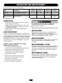
Check at the intervals listed in the following chart:
ITEM
PROCEDURE
Fasteners
Check and tighten as required.
Bearings & Shafts
Check for wear and lubricate.
Battery Maintenance
Replace batteries.
EVERY
3 MONTHS
EVERY
6 MONTHS
EVERY
12 MONTHS
◆
EVERY
24 MONTHS
◆
◆
WARNING
Repeat ALL procedures.
WARNING
GENERAL SERVICE
WARNING
CAUTION
1. Belt loose or needs replacement, adjust with 4 bolts that
support motor to allow 1/4" play.
2. Charge voltage for batteries should be 27.5 +0.05, -0 Vdc
with batteries disconnected (set with R63, shown on the
Control Board Layout page).
3. Replace batteries with Liftmaster P/N MBAT batteries.
Replace in pairs.
To avoid SERIOUS PERSONAL INJURY or DEATH from
electrocution, disconnect ALL electric power BEFORE
performing ANY maintenance.
BATTERY DISPOSAL
SHEAR PIN REPLACEMENT
Replaced batteries must be treated as a hazardous waste and
disposed of in accordance with State, Local and Federal
Regulations. See the battery manufacturer’s Material Safety Data
Sheets (01-30839 “MSDS Sheets, Battery, Standard”).
If gate arm is vandalized and the tapered pin in the output shaft
has been sheared, it must be replaced correctly and with the right
pin type. Replacement must be done by always punching out the
pin (or pieces) from the small end only. If drilling is required, DO
NOT DAMAGE THE SHAFT, use a drill bit smaller than the small
hole size of the pin. (Correct pin (P/N MA013) is a 2" pin with a
number 6 taper only.)
BATTERY REPLACEMENT
Service Kits are available for battery replacement. Please contact
Technical Support (see back of this document for contact
information).
NEVER USE A BOLT AS A TEMPORARY FIX, THIS WILL
DAMAGE THE SHAFT AND COLLAR
1. Use S-3 to rotate bracket to up position
2. Turn off AC power and disconnect batteries small end first.
3. Remove gate arm bracket and pieces in collar
4. Drive out pin pieces with hammer and punch
(Solid sharp blows are better than light ones)
5. Reinstall gate arm bracket
6. Lightly oil the new pin then insert into collar
7. Fully seat pin in shaft by taping on large end
8. Reinstall the arm if required
9. Turn on AC power and connect batteries
10. Turn off S-3 to put gate into operation
BATTERY MAINTENANCE / TESTING
The batteries are maintenance free. However, to insure proper and
safe operation, it is recommended that the batteries be replaced
every two years. Battery testing is conducted automatically. See
the Battery Test Description section for manually initiating the
battery test.
BATTERY HANDLING / STORAGE
Refer to the battery manufacturer’s Material Safety Data Sheets
(01-30839 “MSDS Sheets, Battery, Standard”). LiftMaster does
not recommend storage of batteries in the field. Batteries are
intended for immediate use.
13
TROUBLESHOOTING
WARNING - DISCONNECT BATTERIES AND AC POWER BEFORE
SERVICING ANY MECHANICAL OR MOVING COMPONENTS.
BATTERY CHECKOUT
When the batteries become weak the gate will begin to run
noticeably slower. NOTE: Batteries should only be checked when
you are sure they have had adequate time to fully charge. Turn off
the AC power and run gate for 5 to 10 cycles while observing low
battery indicator LED D12. If LED 12 comes ON, batteries are too
weak to function properly. If LED 12 does not light, then voltage
should be checked as they still maybe near failure. Correct
voltage is approximately 24.5Vdc. NOTE: If LED D12 does light,
gate will open to conserve batteries in this test or in a real power
loss, even if mode switch 8 on S2 is off. Return of AC power will
clear low battery indicator. Correct charge voltage is 27.5 Vdc
with batteries not connected (set with R63, shown on the Control
Board Layout page).
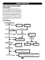
GATE NOT OPERATING
Gate will not operate.
Is the HBEAT flashing?
Check the battery
connections.
No
Check fuse F4.
Replace if blown.
Yes
Is the “BAT LO” LED on?
Is the HBEAT
flashing now?
Yes
No
No
Is S2-8 (open on AC fail) on?
Is the AC PWR
LED on?
Yes
No
No
Is the shadow input active?
Yes
Is the AC power
LED on now?
Clear the active input to
allow the gate to open.
Yes
No
Restore AC power
and/or turn AC
power switch ON.
No
Is the Safety, Backaway, or
Open input active?
Check fuse F3,
Replace if blown.
Clear the active
input to allow the
gate to close.
Yes
No
Yes
Allow unit to charge
before operation.
Does the IRD light while
operating?
Make sure the gate is not binding, then
adjust the IRD. Verify the gate reverses
when obstructed.
Yes
No
Is the IRD flashing?
Yes
The max timer (MRT) has expired. Remove AC and battery power
then reapply to reset. Inspect the belt for slippage and verify the
fast run timer settings are correct.
14
S U G G E S T E D L O O P S E N S O R L O C AT I O N S
FREE EXIT ON VEHICLE APPROACH
Gate will open when sensed by exit loop and then close once the
close loop is cleared. If the vehicle pulls up to the exit loop and
then backs away, it will close (Figure 1).
Space between loops will be 4' to 10'.
Terminal #7 is backaway (free exit).
Terminal #6 is close input.
Back Away Loop
(Free Exit)
Close
Loop
FIGURE 1
ENTRY WITH ACCESS CONTROL DEVICE
Mega Arm
Gate will open when activated by an access control device. When
vehicle passes and clears close loop, gate will close (Figure 2).
NOTE: If a second vehicle tail-gates and is sensed at the close
loop, gate will stop its closing motion until loop is cleared again.
Terminal #6 is close input.
Terminals #1, 2, and 3 are open inputs.
Close
Loop
Card Reader
Tele-entry
Radio Control
DUAL DIRECTION AS ENTRY OR FREE EXIT
Dual direction is a combination of both of the above
configurations to provide the ability for traffic to enter or exit in
the same lane (Figure 3).
Space between loops will be 4' to 10'.
FIGURE 2
Mega Arm
DO NOT ALLOW CONTROL DEVICES TO BE WITHIN 10' OF GATE
OR OPERATOR
RECOMMENDATION 1: If vehicle detectors are used to open or
close the gate, use of the presence contacts are recommended.
Using the pulse contacts will REDUCE the gate’s safe operation.
RECOMMENDATION 2: If closing timer is to be used, use ONLY
on a dedicated free exit.
RECOMMENDATION 3: Close loop must be centered under gate
arm.
Back Away Loop
(Free Exit)
Close
Loop
Card Reader
Tele-entry
Radio Control
FIGURE 3
Mega Arm
15
TRAP INSTRUCTIONS
INSTALL THE K1 AUXILIARY RELAY AND CONNECTOR AT MEGA
ARM CONNECTED TO THE ACCESS DEVICE
1. Press the relay into the K1 location ensuring the pins are
properly aligned.
2. Press the connector into the J1 connector pins.
RECONNECT THE POWER AND TEST
1. Reconnect the DC power by replacing the neutral (Black) wire
to the battery terminal.
2. Reconnect the AC Power to the operator.
3. To test, activate the following sequence of inputs:
a. Open the trap gate using the access device.
b. When the trap gate is open, activate the close loop on the
trap operator. The trap gate will close and the second gate
should open.
c. When the second gate is open, activate the close loop on
the second operator. The second gate should close.
INSTALL THE K1 AUXILIARY RELAY AND CONNECTOR AT THE
SECOND
1. Press the relay into the K1 location ensuring the pins are
properly aligned.
2. Press the connector into the J1 connector pins.
WIRE THE CONNECTIONS BETWEEN THE OPERATORS
1. Connect the Normally open output (NO) of the K1 relay on the
trap unit to the OPEN input (J5 - term#2) of the second unit.
2. Connect the common output (C) of the K1 relay of the trap
unit to the common of the second unit (J5 - term#12).
3. Connect the Normally open output (NO) of the K1 relay on the
second unit to the INTERLOCK input of the trap unit
(J5 - term#8).
4. Connect the common output (C) (J5 - term#12) of the second
unit to the common of the trap unit (J5 - term#12).
TRAP SET UP
Interlock
C
C NC NO DC
S1-6 OFF
S1-8 OFF
K1
OPEN
Trap
SET THE DIP SWITCHES AT THE TRAP OPERATOR
1. Set switch bank S1 to 00100001 where 1 is up and 0 is
down.
2. Set switch bank S2 to 00100010 where 1 is up and 0 is
down.
TES
MA
MA
S1-6 OFF
S1-8 ON
Opener
Common
C NC NO DC
SET THE DIP SWITCHES AT THE SECOND OPERATOR
1. Set switch bank S1 to 00100000 where 1 is up and 0 is
down.
2. Set switch bank S2 to 00100010 where 1 is up and 0 is
down.
TRAP CONFIGURATION
Must use trap kit. See Mega Arm Options Parts List.
Trap Operator
S1
S1
ON
ON
ON
ON
ON
ON
ON
ON
ON
OFF
OFF
Close
Loop Trap
Close
Loop
Center Loop Trap
S2
ON
ON
ON
ON
ON
ON
OFF
Close
Loop
1 2 3 4 5 6 7 8
1 2 3 4 5 6 7 8
S2
ON
ON
ON
Mega ARM Operator
ON
ON
OFF
ON
ON
ON
ON
OFF
1 2 3 4 5 6 7 8
Card Reader Mega Arm Trap
Tele-entry
Radio Control
16
Mega Arm
ON
ON
OFF
ON
ON
ON
OFF
1 2 3 4 5 6 7 8
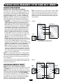
SEQUENCE ACCESS MANAGEMENT SYSTEM (SAMS) WITH “MEMORY”
SAMS WITH OTHER OPERATORS
REQUIRES THE K1 RELAY OPTION (Order SAMS KIT)
This feature allows a logical interface between the MEGA ARM
barrier gate and a swing, slide, etc. gate operator (or MTC-31). All
that is required is 4 wires between the MEGA ARM barrier gate
and the other operator. It will be necessary to have one set of
dedicated/isolated dry contacts - {C. and N.C.} COMMON and
NORMALLY CLOSED be available at the other operator’s OPEN
LIMIT SWITCH. Most units will require that this EXTRA limit
switch be added to their open limit switch assembly (Figure 1).
OPERATION: A one second pulse from access control device to
the MEGA ARM will energize its K1 relay sending an open
signal to the other operator causing it to open. However, the
MEGA ARM’s boom will not raise yet. When the other operator
reaches its full open limit switch, this will open the COMMON
and NORMALLY CLOSED contact on the EXTRA open limit
switch. This will allow the original signal from your access
control device (that was stored in memory) to now raise the
gate arm. As long as the other operator is in the full open
position, any additional open pulse sent will in turn energize
the MEGA ARM’s K1 relay to send another open signal to the
other operator as well as cause the arm to raise again if it has
closed via a car crossing the MEGA ARM’s close loop.
WIRING: Run 2 wires from the other operator’s isolated
common & normally closed contacts of its open limit switch to
the MEGA ARM J5#8 and one of the commons J5, #9-12. Next,
run 2 wires from the MEGA ARM’s K1 relay (common &
normally open) to the other operators common and open input.
(WARNING: max of 30 VOLTS at .5 amps through relay). J5 #8
was the unused SHADOW LOOP input on the MEGA ARM.
NOTE: A separate open device (24 hour timer, toggle switch)
can be run to the other operator to control it without raising
the gate arm. Tampering with the other operator’s safety loops,
safety edges and reverse sensors WILL NOT cause the arm to
raise if one tripped. The arm will only raise if an intended open
signal was sent to the MEGA ARM.
NOTES: For motorized teeth, vertical pivot or overhead operator,
leave S1-6, S1-8 OFF (this will keep the K1 relay latched down
until the arm reaches the down position. This will keep the other
gate operator locked open or teeth locked down until the arm
closes completely).
In this mode, if the arm senses an impact, the K1 relay will stay
energized holding open (or teeth down) the other operator until
the arm times out and closes.
NOTE: Insert a jumper across the JP2 terminal to allow the SAMS
feature to work with the multiple vehicle memory count selection,
use the K1 relay to open the sequenced gate (S1-5 off, S2-6 on,
jumper across JP2). This allows gate to store input counts via J5
#4 but not raise the arm until the sequenced slide or swing gate
has fully opened.
FIGURE 1
Mega Arm
K1 Relay
C
Open Input
NO
C
J5 #11
NC
J5 #8
Access
Device
Extra Open
Limit Switch
J5 #1
J5 #12
S1, #6 and #8 (ON) = K1 Relay PULSE only.
S1, #6 and #8 (OFF) = K1 Relay LATCH only.
FIGURE 2
Mega Arm
Mega Arm
K1 Relay
SAMS TWO MEGA ARMS WITH “MEMORY”
REQUIRES THE K1 RELAY OPTION (Order SAMS KIT)
NOTE: Can be used when you have two entry gates that you want
to SEQUENCE with each other. This is when you can only have
ONE gate raised at a time (bottle neck or gates at a cross street).
In this case, which ever one raises first will get first priority, while
if the other gets an open signal, it will be HELD IN MEMORY,
then raise once the first gate closes. This will work if either gate
has a telephone entry unit or access device (AVI, prox, etc.).
Connect the K1 relay C and N.O. of each gate to the SHADOW
LOOP J5 #8 input and common of the other (Figure 2).
(Leave S1-6 and 8 OFF to allow relay to stay latched.)
Other Operator
(Slide, Swing, Teeth, etc.)
Visitor
Lane
C
NO
J5 #11
J5 #8
Tele-Entry
Reader, etc.
J5 #1
J5 #1
J5 #9
J5 #9
K1 Relay
17
Resident
Lane
J5 #11
C
J5 #8
NO
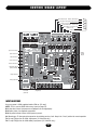
C O N T R O L B O A R D L AY O U T
Open Gate Inputs - Reader, Push Button
Aux Open / Reset (Pulse Open/Close)
Safety Loop Input
Close Gate Input - Close Loop
Back Away - Free Exit Loop
Shadow Loop
Commons - 0Vdc
CLOSE
R21
R16
OPEN 1 OPEN 2 OPEN 3
R24
C3
R23
OLS
D7
R22
OPEN
D6
R33
R39
R44
R48
R43
R59
R43
R63
R25
U5
R58
C12
U12
U7
DX3
X2
CLOSE
D4
R7
U1Ø
DX4
R57
CLS
D3
C13
R56
R6
IRD
D2
C4
U3
R5
CPU
1A DC
R2Ø
R15
+
D9
C5
C2Ø
+
F4
+
B1
R11
HBEAT
K1
Relay (Optional)
D11
BAT LO AC POWER
D12
F3
D14
R13
BAT–
MOV
WARNING FOR
R62
CONTINUOUS
PROTECTION
AGAINST FIRE
DX1
REPLACE ONLY
WITH THE SAME
TYPE AND RATING
OF FUSE
MOTOR
Aux Relay
C NC NO DC
TR
1
B2
J1
–
J4
U19
C8
F1
R55
D25
D26
D1
R2
R51
D2Ø
Q4
D28
R3
Q1
R37
F2
R19
Battery
Charge
Adjust
DX2
R38
JP2
U2
R4
Relay Indicator
U16
Q6
Q5
Obstruction Sense
(IRD and MRT)
R6Ø
D29
Close Limit Sensor
R49
D21
IRD1
R8
R45
C6
Close Drivers On
U15
R4Ø
R26
U6
R9
BRAKE
D5
U14
D27
Motor Brake On
U13
C16
R61
R34
C7
Open Drivers On
X1
R1Ø
R5Ø
C22
Open Limit Sensor
U11
R46
C19
U9
R41
F5
C2
C1
R35
U8
U4
C2
U1
AUX 4 SAFETY 5 CLOSE 6 BACK 7SHADOW 8
D24
8
D23
7
R53
6
1Ø 11 12
D22
5
D19
4
9
T8
T7
R47
3
D18
2
R12
R42
1
8
T6
T5
D17
8
R36
7
7
T4
T3
D16
6
T2
T1
R3Ø
5
S3
D15
R17
4
6
U18
S2
3
5
C18
R18
S1
2
4
R14
D1Ø
1
3
J5
Q2 OPEN
J3
M/S
2
C15
AUX LIMITS
D8
R1
1
MANUAL
1
1
J2
1
+
PWR
K1 Relay
Terminals
(Optional)
ACC+
ACC–
24Vdc
(Regulated)
BAT–
BAT+
24VAC XFMR
MOTOR
BLK RED YEL YEL BLU ORG
INPUT LOCATIONS
Accessory power is 24Vdc regulated rated at 500 ma. [1/2 amp].
NOTE: J5 #8 is now the SAMS with memory input (see page 12).
D11: Heart beat. Shows that processor and program are running properly.
D12: Battery status. See diagnostic procedures.
D14: AC power indicator. Shows that AC power is present.
S3: Manual open. To allow gate to be opened or closed during service of unit. Keep in the “Close” position for normal operation.
F3: 10 amp ATO type fuse for 24Vac input power. (UL listed fuse only.)
F4: 15 amp ATO type fuse for 24Vdc battery input power. (UL listed fuse only.)
18
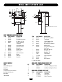
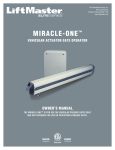
MEGA ARM UL PARTS LIST
20
13
10
21
12
5
18
11
2
16
1
18
8
9
7
17
19
15
3
14
4
NOTE: Mega Arm Tower not shown
6
PART NUMBERS AND DESCRIPTIONS
ITEM
1
2
3
4
5
6
7
8
9
10
11
12
13
PART NUMBER
MA001
MA002
MA003
MBAT
MA005
MA006
MA007
MA008
MA009
MA010
MA011
MA012
MA013
ITEM
14
15
16
DESCRIPTION
Controller
Removable Connector
DC Motor - 24 Vdc
12Vdc 7AH Battery
2 required
Gear Reducer 60:1
Aluminum Chassis
Drive Belt
Reducer Pulley
Motor Pulley
Gate Arm Bracket
Magnet
Cam Arm
Shear Pin
PART NUMBER
MA014
MA015
MA016
17
19
*
MA017
MA019
MA020
*
*
*
*
*
20
21
MA021
MA022
MA023
73A3
74-31243
MA036
MA037
DESCRIPTION
Bolt and Nut (4) Motor
Transformer
120 Vac Duplex Outlet
(120 Vac Only)
Bolt and Nut (4) Reducer
On/Off Switch
Unit Cover for Mega Arm
(Not Tower)
Nylon Arm Nuts (2)
Arm Bolts (2)
Gate Arm - 12'
Filter Module
Surge Suppressor
Collar
Nylon Washer
( * ) parts not shown
PARTS SHIPPED
ITEM
MEGA ARM Operator
Controller
Unit Cover
Installation and Service Manual
Arm Bolts with Washers
Nylon Nuts
7AH Batteries
MEGA ARM TOWER UNIQUE PARTS LIST
QTY
1
1
1
1
2
10
2
ITEM
*
*
PART NUMBER
MA020T
MA020D
DESCRIPTION
Unit Cover for Mega Arm Tower
Unit Door for Mega Arm Tower
MEGA ARM OPTIONS PARTS LIST
ITEM
*
*
*
19
PART NUMBER
71-TRAP
71-SPRINT
71-TRAPSP
DESCRIPTION
Trap option
Sprint option
Sprint Trap option
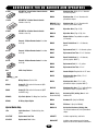
A C C E S S O R I E S F O R D C B A R R I E R A R M O P E R AT O R S
371LM
373LM
374LM
CPT13
CPT33
CPT43
A24
A57
MA201
UN201
SECURITY✚® Single Button Remote Control:
Includes visor clip.
SECURITY✚ 3-Button Remote Control:
Includes visor clip.
MA023
Aluminum Arm: White, 12' x 3" diameter
with warning labels.
MA024
Aluminum Arm: 12' x 3" diameter with
yellow/black stripes.
MA024R (Highly
Recommended)
Aluminum Arm: 12' x 3" diameter with
reflective yellow/black stripes.
MA021
Nylon Arm Nuts: (Pkg. of 50).
MA021A
Nylon Arm Nuts: (Pkg. of 50), thin.
MA031
Adapter Collars: For padded arm option
(2 included).
MA025
Round Padded Arm: 12' x 4" diameter,
yellow.
MA026
Replacement Pad: 12' x 4" diameter, yellow.
MA027
Replacement Arm Tube: 12' x 2" diameter.
MA028
Round Padded Arm: 14' x 4" diameter,
yellow (requires MA117).
MA029
Replacement Pad: 14' x 4", yellow.
MA030
Replacement Arm Tube: 14' x 4".
MA117
Counter Weight: Required for all 15' arms.
MA115
Aluminum Gate Arm: White, 15' x 3"
(requires MA117).
MA116
Aluminum Gate Arm: 15' x 3" with
yellow/black stripes (requires MA117).
MA116R
Aluminum Gate Arm: 15' x 3" with reflective
yellow/black stripes (requires MA117).
MA034 (Highly
Recommended)
Articulating PVC (folding) Arm: 9' with
hardware kit.
MA033
Hardware Kit: (Only for MA034).
MA035
PVC Arm: 9' (Only for MA034).
MA024-10
Articulation Aluminum (folding) Arm:
10' without hardware kit, with yellow/black
stripes.
®
SECURITY✚® 4-Button Remote Control:
Includes visor clip.
Passport 1-Button Remote Control: Includes
visor clip.
Passport 3-Button Remote Control: Includes
visor clip.
Passport 4-Button Remote Control: Includes
visor clip.
24Vdc Loop Detector
Wiring Harness: For the A24.
Heater Kit: 150 watt with thermostat (MA
and MAS only).
Heater Kit: 500 watt with thermostat (MAT
and MATS only).
MA005C
Slip Clutch Option: For Mega Arm Gear Box.
MA200
K1 Relay Output Option
Sprint Units Only:
SP8
Sprint Gate Arm: 8' Padded Safety Arm,
yellow.
SP8 TUBE
Replacement Arm Tube
SAMSKIT
Includes required relay and limits.
SP8 PAD
Replacement Pad: Yellow.
MA230VKIT
Includes surge suppressor, wire jumper,
duplex box covers and detailed instructions.
20
O P E R AT O R N O T E S
21
O P E R AT O R N O T E S
22
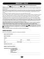
WARRANTY POLICY
(You must read, understand and agree with all items in the limited warranty)
LiftMaster warrants the MEGA ARM-UL to be free of defects in workmanship and materials for a period of 2 years for electronics and
mechanical components and includes a 10 year corrosion perforation warranty on the cover and chassis. Warranty will begin from the
date of purchase.
LiftMaster reserves the right of final determination as to the existence and causes of any defect or failure. Any part or parts found to be
defective and are returned to LiftMaster within the warranty period, shall at our option be repaired or replaced free of charge F.O.B. the
factory. Freight is not included at any time on gate arms and chassis. ONLY UPS ground freight is included during the first year of
warranty.
The warranty will not apply the following circumstances which are considered beyond our control.
Mis-use, vandalism, accident, neglect, unauthorized repairs or modifications, acts of God (lightning, floods, insect damage, etc.), power
surges, units subjected to corrosive environments, incorrect installation or application, the batteries or incorrect battery installation,
operation without or failure to use correct battery type, damage to arm bracket and/or gear reducer due to use of incorrect arm.
The warranty set forth above is entirely exclusive and no other warranty whether written or oral, is expressed or implied. LiftMaster
specifically disclaims any and all implied warranties, merchantability or fitness for a particular purpose. It is the purchasers sole and
exclusive responsibility to determine whether or not the equipment will be suitable for a particular purpose. In no event shall LiftMaster,
inc. be held liable for direct, indirect, incidental, special, consequential damages or loss of profits whether based on contract, tort, or
any other legal theory during the course of the warranty or at any time there after. The installer and/or end user agree to assume all
responsibility for all liability in use of this product, releasing LiftMaster of all liability.
WARNING! MEGA ARM NOT FOR USE WITH MOTORCYCLES, BICYCLES OR PEDESTRIANS. YOU MUST PROVIDE APPROPRIATE
SIGNAGE BEFORE ACTIVATING THE UNIT. NEVER ALLOW CHILDREN TO PLAY NEAR OR OPERATE AUTOMATIC GATES.
IN ORDER TO INSTALL AND USE THE MEGA ARM, YOU MUST UNDERSTAND AND BE IN FULL UNCONDITIONAL AGREEMENT WITH
ALL STIPULATIONS OUTLINED ABOVE. IF YOU ARE NOT IN FULL AGREEMENT, DO NOT PUT UNIT INTO OPERATION. IF OPERATOR
IS PUT INTO OPERATION THIS WILL BE CONFIRMATION THAT YOU ARE IN FULL UNCONDITIONAL AGREEMENT WITH ALL OF THE
ABOVE STIPULATIONS.
Materials, components, features and specifications are subject to change without notice.
WARRANTY REGISTRATION
MAIL OR FAX THIS PORTION TO LIFTMASTER TO CONFIRM YOUR WARRANTY
NAME OF INSTALLING DEALER __________________________________________________________________________
NAME OF CUSTOMER __________________________________________________________________________________
ADDRESS ____________________________________________________________________________________________
CITY ________________________________________ STATE ____________ ZIP CODE ____________________________
MODEL ____________________________ SERIAL NUMBER ________________________________________________
EXPECTED CYCLES PER DAY ________
NUMBER OF HOMES OR APARTMENTS ________
CONFIGURED AS A(N) 1) VISITOR ENTRANCE ________
2) RESIDENT ENTRANCE ________
3) MAIN ENTRANCE ________
4) EXIT ________
5) OTHER (EXPLAIN) ________________________________________________________________
________________________________________________________________________________
23
REPAIR PARTS AND SERVICE
HOW TO ORDER REPAIR PARTS
OUR LARGE SERVICE ORGANIZATION
SPANS AMERICA
INSTALLATION AND SERVICE INFORMATION
SIMPLY DIAL OUR TOLL FREE NUMBER:
1-800-528-2806
www.liftmaster.com
WHEN ORDERING REPAIR PARTS, ALWAYS GIVE THE
FOLLOWING INFORMATION:
• PART NUMBER
• PART NAME
• MODEL NUMBER
ADDRESS ORDERS TO:
THE CHAMBERLAIN GROUP, INC.
Technical Support Group
6020 S. Country Club Road
Tucson, Arizona 85706
01-60162D
©2007, The Chamberlain Group, Inc.
All Rights Reserved