1
M5000 Portable Data Terminal
American Microsystems, Ltd.
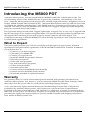
Introducing the M5000 PDT
American Microsystems, Ltd. first introduced the M3000 Portable Bar Code Reader in 1991. The
overwhelming success of the M3000 was due in part to the versatility, and durability of the unit.
Now, American Microsystems introduces the ultra-versatile, high performance, designed-to-fit-yourbudget, M5000 Portable Data Terminal (PDT). American Microsystems came up with the clever idea
to combine the reliability and durability of the M3000 with the convenience and accuracy of a data
terminal. This unit not only has limitless uses, but also has a rugged, simple ergonomic design that
easily fits one-hand and a small budget.
The ergonomic design is built smart: rugged, lightweight, compact, easy-to-use, easy to upgrade and
has the advantage of two superior integrated units. Our specially designed software guides the user
through the data collection process with a four by twenty character line LCD display. Our
competitive advantage is that the M5000 PDT is user friendly especially for non-computer users and
it’s easily flash upgradeable.
What to Expect
This user’s guide provides you with an overall physical description, keypad values, technical
specifications and performance capabilities of the Model 5000 Portable Data Terminal. In addition
you will learn how to:
9
9
9
9
9
9
9
9
9
9
9
9
Connect to your host computer
Customize your M5000 PDT
Connect your input device
Install the M5000 Programmer Software
Run Softcom software
Create and send programs
Use and load built-in programs
Collect and upload data
Send and receive data
Connect and use the M5100 Keyboard Wedge
Connect and use the RS232 Serial interface
Download amended or updated firmware
Warranty
We guarantee that you will be one-hundred percent satisfied with products purchased from
American Microsystems, Ltd., however, you can return the M5000 Portable Data Terminal within
thirty days from the invoice date for a full refund (excluding shipping charges).
A two-year warranty against material defects and workmanship from the date of shipment is
guaranteed by American Microsystems, Ltd. Products are sold on the basis of specifications
applicable at the time of manufacture. AML shall have no obligation to modify or update products
once sold. At our option, we will repair or replace, at no charge, any unit that proves to be defective
providing the appropriate steps are taken to procure an RMA number and shipping instructions
from American Microsystems, Ltd.
1
American Microsystems, Ltd.
M5000 Portable Data Terminal
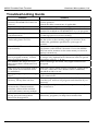
When You Need Support
American Microsystems, Ltd. provides telephone support for all Model 5000 Portable Data
Terminal users. If you have questions or a problem you are unable to resolve after consulting the
operation manual, the Help feature, or our web address, http://www.barcodepower.com, you can
telephone (800) 648-4452 during business hours Monday through Thursday (excluding holidays)
8:00 a.m. to 5:30 p.m. CST and Friday 8:00 a.m. to 5:00 p.m. In addition, you can refer to our
website to download software updates, program updates, and documentation, check for new
releases, firmware revisions and product updates.
You can call for a Return Merchandise Authorization number (RMA) to return the product for
refund or repair. Before contacting Technical Support, please be prepared to furnish the following
information:
9
9
9
9
9
Your company information: company address, ship-to address, telephone number, and
AML customer number
Product model number
Product serial number
Date of purchase
Copy of invoice
When returning the product for a refund, it must be returned prepaid in “like new” condition
including all documentation and packaging (original and unmarked) together with a copy of the
invoice. To expedite the repair process, include information as to the nature of the problem.
Physical Description
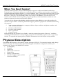
The M5000 PDT features a four-line by twenty character LCD (5 X 7 dot matrix) display and a thirtynine-key keypad. It is fitted with a customized keypad and built-in configuration memory for
optimum use. Parts of the M5000 PDT include:
9
9
9
9
9
9
9
LCD Display
Keypad
Serial Port
RJ45 10-pin Connector
Hand Strap
Battery Compartment
Scanner Triggers (right and lefthand accessibility)
2
M5000 Portable Data Terminal
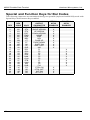
American Microsystems, Ltd.
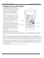
Getting to Know the Keypad
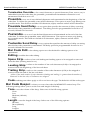
The M5000 Portable Data Terminal is
equipped with thirty-nine keys that are
divided into blue, grey, red and white
keys. When pressed, each key emits an
audible beep that can be disabled if
desired. Refer to Keypad Beep for
instructions on how to disable the key
beep.
The six blue keys consist of Func, four
arrow keys and the Alpha key. The Func
key activates the Select Function menu
during data collection mode. Hot keys
select specific menu items without
scrolling the entire menu. For example,
press F in order to Find Text.
The alpha key toggles between alpha
and normal mode and is used to switch
between upper and lower keys. When in
alpha mode, press a key to insert the
letter that appears on or above the
upper part of the key. A flashing solid
block will let you know when you are in
alpha mode.
Eighteen grey keys represent letters,
special characters, spaces and calculator
keys. Six keys can be used to function as a calculator (+ - * / = %). Each key also serves a dual
function and can be used either in normal or alpha mode except the INS, DEL, EXIT and SPACE
keys.
Red keys are the PWR key and the Enter key. The PWR key is used to power the M5000 PDT on
and off except in M5100 Keyboard Wedge mode. When the M5000 PDT is powered off or laps into
the time-out mode, you will return to the same display at which you were powered off, after you
power on again. The Enter key selects menu items as well as accepts information for an input file.
The remaining thirteen white keys are numeric keys. When in alpha mode, the keys produce the
designated letter with the exception of the plus key. All other numbers, plus sign, minus sign and
decimal are inserted when you toggle to normal mode. A flashing cursor lets you know that you
are in normal mode.
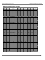
For specific key values, see the chart on the following page.
3
American Microsystems, Ltd.
M5000 Portable Data Terminal
Key Values
Blue Keys
Func
Key Value
Activates the Select Function menu that only operates during data
collection mode (Input). Refer to Select Function Menu for key
descriptions.
Func + Hot Key
Selects specific menu items without scrolling through the entire menu
Alpha
Toggles between alpha & normal modes; inserts the character printed on
or above the actual key
5Up arrow
Moves the display screen up one line at a time or moves the display
screen up one menu level
3Left arrow
Moves the cursor left one character at a time and toggles between menu
selection options
6Down arrow
Moves the display screen down one line at a time or moves the display
screen down one menu level
4Right arrow
Moves the cursor right one character at a time and toggles between menu
selection options
Grey Keys
Alpha
INS
A-Z
Special Keys: ? # $ + - * / = % : ; space @_
Inserts data at the cursor position and moves all existing data to the right
DEL
Deletes characters at the cursor position or if cursor follows a string of
characters, it deletes the characters to the left of the cursor
EXIT
Exits operation being performed
SPACE
Enters the space character
Red Keys
PWR
Enter
White Keys
Numeric
Powers unit off/on
Accepts information in an input file & advances the cursor to the next
input field; also selects menu items
0-9, + - .
When 7 through period (.) are in alpha mode, letters O-Z are produced.
Display Screen
The display screen is a liquid crystal display (LCD) and exhibits up to four lines of text with a
maximum of twenty characters per line. An obvious advantage to this type of display screen is that
you are able to view four lines of twenty characters per line of data at a time.
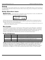
Beep
When pressed, each key emits an audible beep that can be disabled if desired. Choose Setup from
the Main Menu, arrow down and choose Other Setup, arrow down to select Keypad Beep; use
either left or right arrow key to toggle the off/on option.
4
M5000 Portable Data Terminal
American Microsystems, Ltd.
The M5000 PDT also provides an audible beep when a bar code has been successfully scanned. To
change the tone and length of the beep, choose Setup, Bar Codes, Bar Code Beeper and toggle
between desired beeper options.
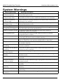
Other beep sequences are programmed to let you know about possible problems. For a full range
of system errors, please refer to System Warnings.
Batteries
Three AA alkaline batteries are used to power the M5000 PDT and serve as a power source for
input devices attached to the unit. When the battery power drops below an adequate level, the unit
indicates Battery Low on the display screen. To replace the batteries, follow the steps below:
1.
Turn off the power to the M5000 PDT.
2.
Place the unit face down and unlatch the bottom strap from the unit.
3.
Press down slightly on the battery compartment and slide the cover to the right, away from
the case.
4.
Carefully lift the batteries from the case.
5.
Replace the batteries with three new AA batteries in the positions indicated by the diagram
inside the compartment.
6.
Replace the battery cover by sliding it to the left until it snaps into place.
7.
Replace the hand strap latch into its fastener.
The internal lithium battery provides backup power that supports the RAM memory when the
main batteries are removed. Collected data as well as system defaults including the internal clock
are protected by backup battery power.
Taking Care of your M5000 PDT
Protect your M5000 Portable Data Terminal from damage by following the simple
recommendations below.
Electrical components can be damaged by exposure to intense electrical fields, therefore avoid
exposing the M5000 PDT to the following conditions:
9 Avoid electrostatic discharge produced by friction such as heavily carpeted areas during
periods of low humidity.
9 Avoid using the unit with a modem during electrical storms.
9 Avoid exposure to sources of intense arcing
9 Avoid exposure to powerful electromagnetic fields such as large motors, induction coils,
transformers, etc.
9 Avoid exposure to sources of ionizing radiation such as x-rays, etc.
Mechanical components can be damaged by exposure to the following conditions:
5
9
Direct exposure to water—do not immerse
9
Physical contact or hard impact
9
Extreme heat or open flame; do not leave on a vehicle dashboard or enclosed vehicle
9
Highly corrosive environments
9
Strong industrial cleaning solvents
American Microsystems, Ltd.
M5000 Portable Data Terminal
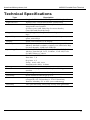
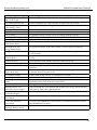
Technical Specifications
Type
Dimensions
Input Devices
Accessories
Keypad
Special Keys
Display
Memory
Symbology Decodes
Serial
Microprocessor
Interface
Power
Durability
Environmental
Warranty
Description
Height: 7 .75” Width: 3.75” Depth: 1.625” Weight: 13 oz.
Wand, Laser, CCD & Slot Reader (undecoded)
M5100 Keyboard Wedge, Memory Module, M5005
Integrated Laser Scanner
(Contact your AML Sales Rep for more details.)
Case, Belt and Shoulder Strap
39-key keypad with alphanumeric & special character
keys
Alphanumeric, function, insert, delete, exit, power,
space, arrow keys
4-line X 20 character LCD display
256K bytes standard RAM memory with expandable
Memory Module available (contact your AML Sales Rep
for more details); 2 MB flash EPROM
Code 39, UPC-A, UPC-E, EAN-13, EAN-8, UPC/EAN
Addons, Interleaved 2 of 5, Codabar , Code 128, Code
93, MSI/Plessey, Code 11
Baud rates: 300-57600
Data bits: 7, 8
Stop bits: 1, 2
Parity: none, odd, even
Intercharacter delay: 0-99ms
16.67 MHz
RS-232 Serial, optional M5100 Keyboard Wedge or
modem
Operating: 3 AA batteries Backup: Lithium
Shock resistant with drops up to 6’
Operating temperature: 0° centigrade to +50°
centigrade (+32° Fahrenheit to +120° Fahrenheit)
Relative humidity: 5% to 95% (non-condensing)
Two-year warranty, thirty-day money back guarantee
6
M5000 Portable Data Terminal
American Microsystems, Ltd.
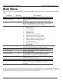
Main Menu
When you first power on the M5000 PDT, the Main Menu prompts you to select from the following
options.
Function
Input
Communications
Hot Key
I
C
Setup
S
Status
?
Calculator
A
Erase
Copy program
E
P
Non-port mode
N
Time
T
LCD Contrast
Upgrade Flash
L
U
Description
Initiates data collection.
Allows transfer of files between the M5000 PDT &
the PC.
Configures all system-wide parameters:
Date/Time, Bar Codes, Comm. Setup, Laser/CCD
options, Other Setup, and Reset Setups.
Displays the following information:
9 ROM version
9 ROM Checksum
9 Flash Version
9 Total Memory
9 Number of bytes available
9 Percentage of memory available
9 Total number of Programs stored
9 Total number of Lookup files stored
9 Total number of Data files stored
9 AA Battery status
9 Lithium battery status
9 Recall Data
Provides access to a 4-function calculator. (Alpha
mode is not active during calculator mode.)
Erases stored data, lookup and program files.
Loads a built-in program into RAM that enables
you to collect data.
Places M5000 PDT in either M5100 Keyboard
Wedge mode or RS-232 non-portable mode.
Displays setting for the year, month, day, hour,
minute, second, a.m. or p.m.
Adjusts display contrast with left and right arrows.
Updates the M5000 PDT using the communications
interface cable, PC, and M5000 Programmer
software.
Note: Five minutes after the last activity is performed on the M5000 PDT, it automatically powers off. This
timeout can be adjusted from one to sixty minutes (refer to Setup, Other Setup, Timeout). When you power on
the M5000 PDT again, the last menu that you accessed is then displayed.
7
American Microsystems, Ltd.
M5000 Portable Data Terminal
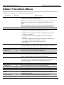
Select Function Menu
During data collection mode (Input), you can press the Func key, and the Select Function menu
prompts you to choose one of the following functions:
Function
Find
Hot Key
F
Goto Record
Status
G
?
Insert Record
I
Clear
Calculator
Erase
Recall
C
A
E
R
Store
S
First Record
Last Record
Prev. Record
Next Record
View Lookup
Time
M
N
J
K
V
T
LCD Contrast
L
Description
Allows you to search during input mode for a string of
characters that match the find text.
Up arrow searches for a match previous to the current field.
Down arrow searches for a match following the current
field.
Enter searches for the first match from the beginning of the
file. (Search method used for scanning within this field.)
Moves to a specified record
Displays the following information:
9 ROM version, ROM Checksum, Flash version
9 Total memory, number of bytes available, percentage of
memory available
9 Current record, current program stored, current file
stored
9 Number of program files stored, number of lookup files
stored, total number of data files stored
9 AA Battery status, Lithium battery status
9 Recall data
Inserts records into Input and Program modes. While
collecting data, press Func, then press I (Insert) to insert an
empty data record before the one being viewed.
Clears an entire input field
Provides access to a 4-function calculator
Erases a record or an entire data file
Inserts data that has been stored with the Store function.
Press Func, then R (Recall); the information is inserted in
place of existing data in the current input field.
Stores the current input field to be used with the Recall
function. Press Func, then press S (Store); the information is
stored in memory and can be recalled using Func R
(Function Recall).
Moves to the first record of the current program
Moves to the last record of the current program
Moves to the previous record of the current program
Moves to the record after the current record
Displays selected lookup file
Displays setting for the year, month, day, hour, minute,
second, a.m. or p.m.
Adjusts display contrast with left and right arrows
8
M5000 Portable Data Terminal
American Microsystems, Ltd.
Quickly Getting Started
This section takes you through the basics of installing the M5000 Programmer in Windows and
connecting your input device to the M5000 PDT. It also shows you how to use built-in programs,
create your own program, how to load a program, as well as how to collect and upload data to your
computer. You can refer to the Help feature in the M5000 Programmer for further details on all dialog
prompts used in the examples presented.
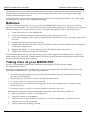
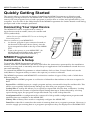
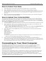
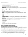
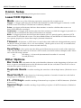
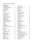
Connecting Your Input Device
The M5000 PDT can be coupled with a variety of
input devices such as wands, lasers, slot readers and
CCDs (undecoded).
Note: Be sure your M5000 PDT is not on during the
connection process.
How to connect to your M5000 PDT:
1. As shown, plug the 9-pin connector located on
the bottom of the input device (laser), into the
9-pin receptacle located on the top of the M5000
PDT.
2. Turn on the power to your M5000 PDT. (In
M5100 Keyboard Wedge mode, power is
automatically received from the PC.)
M5000 Programmer
Installation & Setup
To install the M5000 Programmer and related
utilities, insert the CD-ROM into the drive, and follow the instructions presented by the installation
wizard (you may need to manually start the Setup.exe application if the installation wizard does not
start automatically).
To uninstall the M5000 Programmer or related utilities, click on Start, Control Panel and use the
Add/Remove Programs utility to remove the options you wish to uninstall.
The M5000 Programmer and M5000 PDT work with a number of types of files, each of which has a
different purpose.
Program File─a M5000 program is a collection of identifiers that indicate to the user a request for
data.
Project File─a M5000 project is a single program and any associated lookup file and data file. This
allows you to quickly and efficiently manage any files that your program is using.
Lookup File─a lookup file allows you to specify an input field used for data verification. Lookup
file data restricts the contents of specified input during data input. Unless allowed by a lookup
option during input, the program accepts data listed only in the lookup data file.
Configuration File─a configuration file contains all of the possible configuration properties and
attributes that are available on the M5000 PDT.
Library File─a library file is used to completely configure the M5000 PDT.
Data File─a data file is created as the result of entering data into a program's prompts. However, it
can also supply pre-existing data to a program's prompts as they are displayed on the M5000 PDT.
9
American Microsystems, Ltd.
M5000 Portable Data Terminal
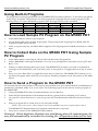
Using Built-In Programs
Six programs are pre-programmed into the M5000 PDT for data collection. To use these programs,
select Copy Program. The prompts for each program (P1 through P6) are as they appear in the
display below. Comma delimited programs (P2C through P5C) are also included.
P1
ITEM NUMBER
P2
P3
P/N
P/N
QTY
QTY
P4
P5
P/N
LOC
QTY
P6
P/N
UOM
QTY
DESCRIPTION
Rec 1 of 1
Rec 1 of 1
Rec 1 of 1
Rec 1 of 1
Rec 1 of 1
Rec 1 of 1
How to Load Sample P2 Program on the M5000 PDT
1.
In the Main Menu, select Copy Program.
2.
Arrow down and select sample P2 program. The prompt reads Copying P2 to RAM, then P2
Copied to RAM, press any key.
3.
After you press any key, the Main Menu appears. The P2 program is loaded and ready to collect
data.
How to Collect Data on the M5000 PDT Using Sample
P2 Program
1.
In the Main Menu, select Input. Choose P2 from the Select Program list.
2.
Select *New File* and input a filename. (You are now prompted to enter data: (P/N, QTY and
Rec 1 of 1.)
3.
When you finish entering data, press exit. The M5000 PDT prompts you with a confirmation
message to Exit Data Entry Are You Sure? (No), to exit press Y or toggle the arrow key to select
yes.
4.
Press Y to Save Data File? or toggle the arrow key to select yes. The M5000 PDT returns you to
the Select Program menu where you can choose another program or exit and return to the Main
Menu.
How to Send a Program to the M5000 PDT
We assume that the serial cable is connected to an available com port and all default communication
parameters (xmodem, 9600, N, 8, 1) are used. The following steps can be used to send a program to
the M5000 PDT.
1.
Using the M5000 PDT select Communications, choose Receive.
2.
Select RS-232 Serial under Communications Mode, (prompt shows Waiting for Connect).
3.
On your PC, select Send icon or you can go into the Communications Menu and choose Send
File.
4.
Select a program file to send, choose ok, and select Send.
Note: If an error occurs, select Setup to choose an available com port or repeat steps 2 and 3.
The M5000 PDT displays Receive Complete when the file is received.
5.
Press exit to return to the M5000 PDT Main Menu.
Warning! When duplicate filenames are used during data file transmission, the
new file automatically overrides the existing file. All previous data will be lost.
10
M5000 Portable Data Terminal
American Microsystems, Ltd.
How to Collect Your Data
1.
In the Main Menu, select Input, and select the program that you downloaded.
2.
Select *New File*, and input a filename. (You are now in data collection mode.)
3.
When finished with data collection, press exit; you are prompted with a confirmation message,
Exit Data Entry, Are You Sure? (No). You can either press Y or toggle with the arrow key to
select yes.
4.
Press Y or press enter at Save Data File (Yes)? This action returns you to the Select Program
menu, press exit to access Main Menu.
How to Upload Your Collected Data
We assume that the serial cable is connected to an available, functioning com port and all default
communication parameters (xmodem, 9600, N, 8, 1) are used. If a timeout error occurs during this
process, you will need to repeat all the steps to upload collected ASCII data. (Refer to Transmitting
Files Using the M5000 PDT for details on ASCII files.)
1.
Using the M5000 Programmer software on your PC choose Communications, then Receive File.
2.
Enter a filename (.TXT) to receive and select Save. This action takes you to the Receive File
dialog where you select Receive; Status Shows Waiting.
Note: If Error Opening Com Port appears on the screen, click ok. Then select Communications,
Setup and change the serial port to the available port you are using. (Default is Com1.)
3.
In the Main Menu on the M5000 PDT, choose Communications, and select Send, Data Files.
Status shows:
Sending (data file name)
100% complete
Transmit complete
Press any key
The M5000 Programmer status box displays Completed when a file is successfully received.
Note: You can view the file with a text editor or word processor.
4.
Once your file is successfully transmitted and a key is pressed you are prompted by a
confirmation message, Erase Uploaded Data Files? (No), if desired, press Y or toggle the arrow
key to select yes. When yes is chosen, the M5000 PDT verifies your selection and returns you to
the Communication Select menu. Press exit to return to the Main Menu.
Connecting to Your Host Computer
The M5000 Portable Data Terminal can be connected to your host computer with the M5100
Keyboard Wedge (optional accessory), RS-232 serial or a Hayes compatible modem.
The M5100 Keyboard Wedge configuration integrates a specialized decoder between the host
computer and the M5000 PDT allowing you to transmit data directly to your computer via the
keyboard interface port.
The RS-232 serial configuration utilizes communications software to a) transfer data directly into
your application as keyboard data using Softcom, b) transfer data and programs back and forth
between your host computer and the M5000 PDT using the M5000 Programmer software.
The M5000 Portable Data Terminal supports xmodem protocol and can be connected to a Hayes
compatible modem through the RS-232 serial port.
11
American Microsystems, Ltd.
M5000 Portable Data Terminal
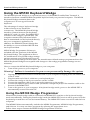
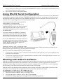
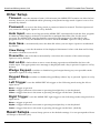
Using the M5100 Keyboard Wedge
The M5100 Keyboard Wedge is an optional accessory of the M5000 Portable Data Terminal. It
interfaces between a standard IBM compatible keyboard and your personal computer. The M5100
Keyboard Wedge transmits data to the
computer as if it were typed from the
keyboard.
The advantage of using a keyboard wedge
is that software is not needed for
connectivity. The M5100 Keyboard Wedge
interface connects between the keyboard
and the PC with a Y-cable. The M5000 PDT
connects to the wedge to upload data. The
computer remains fully functional while
data is transmitted via the keyboard directly
into your computer’s application. In
addition, the M5100 Keyboard Wedge has
the ability to convert standard RS-232 data
into keyboard data.
M5100 Wedge Programmer Software is
included with the purchase of the M5100
Keyboard Wedge. This application allows
for modification of keyboard wedge settings
such as transmit speed, keyboard type and
RS-232 conversion settings. In most cases, the manufacturer default settings programmed into the
M5100 Keyboard Wedge are acceptable and changes to the wedge programmer settings are not
necessary.
How to connect the M5100 Keyboard Wedge to your computer:
1. Turn off the power to your computer.
Warning! Failure to terminate the power can permanently damage the system.
2.
3.
4.
5.
6.
7.
Unplug the keyboard connector from the back of your computer and plug it into the female end
of the Y-cable.
Plug the male end of the Y-cable into your keyboard port.
Connect the wedge to the 9-pin connector on the Y-cable.
Connect the interface cable to the 9-pin male connector on the wedge.
Connect the RJ45 10-pin connector end (resembles a telephone jack) of the interface cable to the
bottom of the M5000 PDT.
Turn on the power to your computer. In keyboard wedge mode, power to the M5000 PDT is
automatically received from the PC.
Using the M5100 Wedge Programmer
When the keyboard wedge cable is connected, the M5000 PDT switches to the keyboard wedge
mode automatically. During keyboard wedge mode the M5000 PDT receives all its power from the
keyboard port and does not use its internal battery. The M5000 PDT turns on and off with the host
computer.
The M5000 Utilities automatically includes the M5000 Programmer, M5100 Wedge Programmer,
and Softcom. You may run these programs by selecting the appropriate icon.
Follow these steps to initiate the M5100 Wedge Programmer software:
12
M5000 Portable Data Terminal
American Microsystems, Ltd.
1.
To start the Wedge Programmer, choose Start, select Programs, select M5000 Utilities, select
M5100 Wedge Programmer program icon.
2.
When you start the wedge programmer and have made necessary changes, choose OK to
accept the settings.
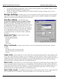
Wedge Settings—define options such as interface mode, keyboard type, strip linefeeds,
caps lock, num lock, auto caps, and alternate scan code however, default settings are acceptable
and in most cases software changes are not necessary.
Interface Mode—the M5100 Wedge
Programmer settings include two modes for data
transfer, the M5000 PDT mode (default) and the
RS232 Serial mode. The M5000 PDT mode is the
recommended method to transmit data while using
the M5000 PDT. The RS-232 Serial mode is used
when connecting an RS-232 device for the purpose
of converting its output to keyboard data. Options
for the RS-232 Serial must match the settings on
your RS-232 device in order for data to transmit
correctly.
Keyboard Type—option used to select
keyboard type include:
US standard (English)
German
French
Italian
Universal
Strip Linefeeds—option used to remove the line feed character from the data. Options
include:
None
LF CR (line feed, carriage return)
CR LF (carriage return, line feed)
Always
Caps Lock—select either on or off to match the computer keyboard Auto Caps setting. If the
Auto Caps option does not operate on your computer, use this function. Select on when the host
computer’s keyboard Caps Lock setting is on. This setting transmits lower case alpha characters as
shifted characters. Select off when the host computer’s keyboard Caps Lock is off. This setting
transmits upper case alpha characters as shifted characters.
Num Lock—select either on or off to match the computer keyboard Auto Caps setting. If the
Auto Caps option does not operate on your computer, use this function. Select on when the host
computer’s keyboard num lock setting is on. This setting transmits lower case alpha characters as
shifted characters. Select off when the host computer’s keyboard num lock is off. This setting
transmits upper case alpha characters as shifted characters.
Auto Caps mode—the M5000 automatically transmits data in the correct
upper and lower
case, whether the host computer’s keyboard settings is on or off when Auto Caps is on.
13
American Microsystems, Ltd.
M5000 Portable Data Terminal
Alternate Scan Code—this option is used only for computers that run Scan Code Set 3
(some Xwindows terminals and concurrent DOS).
Serial Port Settings—allows the Wedge Programmer to select the baud rate,
parity and data bits and are applicable only in RS-232 serial mode.
Baud Rate—sets the transmission speed for the serial port on the wedge and must match the
baud rate of the RS-232 device. Select one of the following:
300
2400
19200
600
4800
38400
1200
9600
Data Bits—sets the character length (number of data bits per character) for serial data and
must match the data bits setting of the RS-232 device. Select either 7 or 8.
Parity—the parity setting must match the parity setting of the RS-232 device. Parity is used to
provide a self-checking method for data transmission. Select one of the following:
None
Even
Odd
Mark
Transmit Speed—this option incorporates a slide bar and sets the speed at which data will
be transmitted to the computer. Older computer systems may require the transmission speed set to
a slower rate.
Diagnostics—option that executes a self-test program and performs the following tests on
the M5000 PDT. Close the Diagnostics window when tests are completed.
RAM Test
ROM Checksum
EEPROM Test
Character Set
LED Test
RS-232 Serial Loopback Test (loopback connector required)
RTS/CTS Loopback Test (loopback connector required)
Status Log
How to Upload Collected Data
Using the M5100 Keyboard Wedge
We assume that you followed the previous steps in this section, connecting the M5100 Keyboard
Wedge and the interface cable, you are now ready to upload the collected data. The cursor must be in
the active application for you to upload your data. You can use Notepad for testing your M5000 PDT
program settings.
1.
In the Main Menu of the M5000 PDT, choose Communications, select Send, Data Files.
2.
From your PC, select the M5000 Programmer, select Communications, Send and then select the
collected data file. Your data then begins transmitting into your application and appears as
keyboard data.
3.
Once your file is successfully transmitted and a key is pressed you are prompted with a
confirmation message to Erase Uploaded Data Files? (No), if desired, press Y or toggle an arrow
14
M5000 Portable Data Terminal
American Microsystems, Ltd.
key to select yes. When yes is chosen, the M5000 PDT verifies your selection and returns you to
the Communications Select menu.
4.
Press exit to return to the Main Menu.
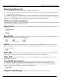
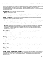
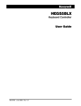
Using RS-232 Serial Configuration
The M5000 PDT uses software developed by American Microsystems, Ltd. and runs on a Windows
compatible computer. With the help of M5000 Programmer software, programs or data files can be
transferred back and forth between the M5000 PDT and your host computer. Softcom can also be
utilized when uploading data to emulate keyboard input.
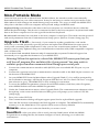
As pictured, the RS-232 serial interface is
established by connecting the
communications interface cable to an
available RS-232 port on the host computer
and attaching the RJ45 10-pin connector
(resembles a telephone jack) to the bottom of
the M5000 PDT.
You must utilize the M5000 Programmer
software to generate and transfer custom
programs and configurations to the M5000
PDT for data collection in portable mode.
To use the M5000 PDT in RS-232 serial nonportable mode select Non-port mode from
the Main Menu (or press N). Use Softcom to
enable RS-232 serial data to appear as
keyboard data to the PC.
Parameter settings such as baud rate, data
bits, parity, etc. are preprogrammed at the manufacturing plant. These parameter settings can be
changed through Comm. Setup (Communications Setup).
How to connect the M5000 PDT to your computer:
1.
Connect the 9-pin end of the communications interface cable (RS-232) into an available RS-232
port on your computer.
2.
Connect the opposite end of the communications interface cable to the RJ45 10-pin connector on
the bottom of the M5000 PDT.
Working with Softcom Software
Softcom is a memory-resident PC program that allows data received from the serial port to appear as
direct keyboard input and can be used with a bar code reader or serial output device. Softcom
supports a wide range of serial port options and also supports flow control. Flow control regulates
the incoming serial data and prevents the buffer from overflowing.
Softcom runs in the background monitoring data from the serial port. When data is read from the
serial port, the currently active application receives the data as keyboard input.
Installation & Setup for Windows
1.
2.
3.
15
Insert the Softcom diskette into your floppy drive.
From the Windows taskbar, choose Run, type a:/setup.
Installation dialogs guide you through the rest of the setup process.
American Microsystems, Ltd.
M5000 Portable Data Terminal
Running Softcom 32:
1.
2.
To start Softcom, from the Windows taskbar, choose Start.
Select Programs, choose Softcom 32 and select Softcom 32 program icon. The application runs
from the Windows task tray.
If you need to change the communications options, right-click on the Softcom icon in the task tray
and choose Configuration. Softcom has the option to automatically load when Windows starts. In
addition, you can disable Softcom, exit the application or utilize the test utilities.
Softcom Communications
Softcom options such as serial port, baud rate, parity, data bits, stop bits and xon/xoff flow control
are defined by selecting Communications.
Serial Portdefines the PC serial communication port that Softcom uses. Select one of the
following:
Com1 (default)
Com2
Com3
Com4
Baud Ratesets the transmission speed for the serial port and must match the baud rate of
the M5000 PDT. Select one of the following:
300
600
1200
2400
4800
9600 (default)
19200
38400
57600
Paritythe parity setting must match the parity setting of the M5000 PDT. Parity is used to
provide a self-checking feature in your data transmission method. Select one of the following:
None (default)
Odd
Even
Data Bitssets the character length (number of data bits per character) for serial data and
must match the data bits settings of the M5000 PDT. Select either 7 or 8 (default).
Stop Bitsdefines the number of stop bits used during serial communication, choose 1
(default) or 2 stop bits.
Xon/Xoff Flow Controlenables xon/off software flow control during serial
transmission. When receiving serial data, the M5000 PDT transmits a xoff character to stop
incoming serial data and prevents the serial buffer from overflowing. When the M5000 PDT is
ready to accept more data, a xon character is transmitted.
On (default)
Off
Keyboard Settingsallows function key and special key translation.
16
M5000 Portable Data Terminal
American Microsystems, Ltd.
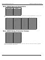
Function Keys—with Function Keys enabled, the M5000 PDT can accept ASCII characters
and transmit a corresponding function key to the computer. The ASCII characters and values are
listed in the table below:
Function Key
No Function Keys
Use DC1-SUB
(11H-1AH)
Use 81H—8AH
Use Both
Description
No function key translation. (default)
ASCII characters 17-26 represent function keys F1F10.
Note: with this option on, it is not possible to represent
the normal ASCII characters 17-26.
Function keys F1-F10 are represented by extended
ASCII characters 129-138.
Note: with this option on, it is not possible to represent
the function keys in a bar code because all bar code
symbologies support only the ASCII character set from 0127.
Function keys F1-F10 are represented using both
ranges DC1-SUB and 81H-8AH.
Special Keys—with Special Keys enabled, the M5000 PDT can accept a given non-ASCII
character and transmit a corresponding special key to the computer. The ASCII characters and
values are listed in the table below:
Special Key
No Special Keys
Use 01H—1FH
Use 8CH—9BH
Use Both
Description
No special key translation. (default)
Special keys are represented within this range.
Note: with this option on, it is not possible to represent
the normal ASCII characters 17-26.
Special keys are represented within this range.
Note: with this option on, it is not possible to represent
the special characters in a bar code because all bar code
symbologies support only the ASCII character set from 0127.
Special keys are represented using both ranges 01H—
1FH and 8CH—9BH.
Daisy Chainingoption not applicable with the M5000 PDT.
17
American Microsystems, Ltd.
M5000 Portable Data Terminal
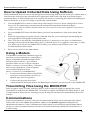
How to Upload Collected Data Using Softcom
While minimized, Softcom runs in the background monitoring data from the serial port. When data is
read from the serial port, the currently active application will receive the data as keyboard input.
Assuming that you followed the previous steps in this section, connecting the cable and enabling the
Softcom software, you are now ready to upload the collected data.
1.
Use the M5000 PDT to select Comm. Setup and change Protocol to None; change Flow Ctrl to
Xon/xoff. The remaining communications parameters must match Softcom settings.
Note: Since Softcom emulates keyboard data, the cursor must be in the active application you wish to
upload your data to.
2.
On your M5000 PDT select the Main Menu, choose Communications, then select Send, Data
Files.
Select the appropriate program and the collected data file, your data begins transmitting into
your application and appears as keyboard data.
Once your file is successfully transmitted and a key is pressed you are given a confirmation
message to Erase Uploaded Data Files? (No), if desired, press Y or toggle the arrow key to select
yes. When yes is chosen, the M5000 PDT verifies your selection and returns you to the
Communications Select menu.
Press exit to return to the Main Menu.
3.
4.
5.
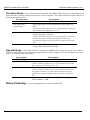
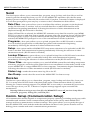
Using a Modem
The M5000 Portable Data Terminal supports
xmodem protocol and can be connected to a
Hayes compatible modem through the RS232 serial port as shown. (You need to
purchase either a 9-pin or 25-pin modem
cable to connect to your modem.) Collected
data can be uploaded to a host computer
over standard telephone lines.
How to connect to your M5000 PDT:
1.
2.
Connect the modem cable to the RS-232
serial port on the modem. (9 to 25 pin
adapter may also be required.)
Connect the opposite end of the
communications interface cable to the RJ45 10-pin connector on the bottom of the M5000 PDT.
Transmitting Files Using the M5000 PDT
Data, program, setup, lookup, and clone files as well as status log and hex dump files can be
transmitted to and from the M5000 PDT. This section outlines the M5000 PDT Send, Receive, and
Communication Setup menus. Pressing any key during file transmission immediately aborts the
transfer.
Communications
Files are transmitted to your PC using the Communication Select menu and cannot be edited
without the use of the M5000 Programmer. (Refer to the M5000 Programmer Help File for
additional information.) The Communication Select menu is accessed through the Main Menu,
where you select Communications and choose from the following submenus: Send, Receive, or
Comm. Setup.
18
M5000 Portable Data Terminal
American Microsystems, Ltd.
Send
The Send option allows you to transmit data, program, setup, lookup, and clone files as well as
status log and hex dump files from your PC. As the M5000 PDT transmits a file, the file status
displays percent complete. When the file reaches 100% Complete, Transmit Complete is displayed.
You are then prompted to press any key to return to the Communication Select menu.
Data Filesthis option allows you to send data files within a program via the keyboard
wedge, RS-232 serial, or modem. You can send all data files or individual data files with
transmission beginning immediately following the selection of either transmission mode
(keyboard wedge, RS-232 serial or modem).
When All Data Files is selected, the M5000 PDT transmits every data file stored in your M5000
PDT. If you want to send data from a specific program, select the program, choose All Data Files
for that program, or select a specific data file saved using that program. When either option is
selected, the M5000 PDT prompts for one of the communication modes by default.
Programsthis option allows you to upload program files via RS-232 serial or modem.
You can send all program files or individual programs with transmission beginning
immediately following the selection of either transmission mode.
Setupthis option enables all M5000 PDT setup menu selections to be uploaded via RS-232
serial or modem with transmission beginning immediately following the selection of either
transmission mode. (RS-232 serial or modem)
Lookup Filesthis option allows you to upload lookup files via RS-232 serial or modem.
You can send all lookup files or individual lookup files with transmission beginning
immediately following the selection of either transmission mode (RS-232 serial or modem).
Clone Filesthis option enables you to send all M5000 system files including setup menu
selections, programs, and lookup files (data files are not transmitted via this mode) stored in the
source M5000 PDT to a target M5000 PDT or host computer. Transmission begins immediately
following the selection of either transmission mode (RS-232 serial or modem).
Status Logsends the current status log file to the PC.
Hex Dumpsends a hex file stored in the M5000 PDT for data recovery.
Receive
The Receive option allows you to obtain data, program, setup, lookup and clone files, from your
PC. You must select RS-232 Serial or Modem mode under Communications Mode. By default
Waiting for Connect message appears. The M5000 PDT is now ready to automatically receive the
correct file type from your PC. A Receive Complete message appears upon successful file
transmission.
Warning! When receiving a new clone file, the M5000 PDT erases all previous Setup Menu
selections, programs, lookup files, and data files.
Comm. Setup (Communication Setup)
All communication modes depend on components properly operating, including serial ports, cable
assemblies and modems. Serial communication parameters must exactly match M5000 PDT
settings and host communications software settings. This option allows you to specify the type of
data the M5000 PDT sends and the mode that transmits the data. It also presets features such as
dialing, phone number and serial communications parameters.
19
American Microsystems, Ltd.
M5000 Portable Data Terminal
You can use one of two ways to access Communication Setup. From the Main Menu arrow down
to Communications, then choose Comm. Setup. Another method you can use to access
Communication Setup (Comm. Setup) from the Main Menu, is simply arrow down to Setup, and
choose Comm. Setup.
Protocol—select one of the following options:
None—protocol is not used.
Xmodem—enables the xmodem protocol that is commonly used to ensure data integrity when
communicating via telephone lines. The M5000 PDT automatically detects and supports
xmodem CRC and xmodem checksum. Default is set the Xmodem.
Flow Control—is used when receiving serial data and prevents the serial buffer from
overflowing. Select one of the following options:
None—flow control is not used.
Xon/xoff—enables Xon/xoff software flow control. When receiving serial data, the M5000 PDT
transmits a xoff (Ctrl S) character to stop incoming serial data and prevents the serial buffer from
overflowing. When the M5000 PDT is ready to accept more data, a xon (Ctrl Q) character is
transmitted.
RTS/CTS—enables RTS/CTS hardware flow control. When receiving serial data, the M5000
PDT drops the RTS line to stop incoming serial data and prevents the serial buffer from
overflowing. When the M5000 PDT is ready to accept more data, the RTS is again inserted.
Default is set to RTS/CTS.
Baud Rate—sets the data transmission speed for the serial port on the M5000 PDT and must
match the baud rate of the host computer’s serial interface. Select one of the following options:
300
2400
19200
600
4800
38400
1200
9600 (default)
57600
Parity—the M5000 PDT parity setting must match the parity setting of the host computer’s
serial interface and is used to provide a self-checking feature in your data transmission method.
Select one of the following options:
None (default)
Odd
Even
Data Bits—sets the character length (number of data bits per character) for the serial data
and must match the data bits setting of the host computer’s serial interface. Select either 7 or 8
(default).
Stop Bits—defines the number of stop bits used during serial communication, choose 1
(default) or 2 stop bits.
Char Delay (Character Delay)—specifies the amount of delay inserted between
each transmitted character. This option slows the transmission rate to compensate for slow host
computers that require time to process each character. Programmable range is 0ms to 99ms.
(Default is one.)
20
M5000 Portable Data Terminal
American Microsystems, Ltd.
Data—select one of the following options. (Default is Menu.)
Menu—allows you to select specific data files for transmission.
Send All—transmits all data files stored and avoids the Upload Selection menu.
Mode—specifies which mode is automatically used when the M5000 PDT transmits data. You
are not required to specify the transmission mode each time data is transmitted (unless Menu is
enabled). You are required to manually select one of the following transmission modes each time
the M5000 PDT transmits data: Kbd Wedge, RS232 port or modem. (Default is Menu.)
Dialing—sets the modem for telephone dial type, either Tone (default) or Pulse.
Phone Number—sets the destination telephone number for modem communications.
Modem Init—sets the modem initialization string for modem communications.
Modem Time Out—when checked, this setting aborts Transmit Receive mode after
approximately four minutes, fifteen seconds, if a call is not received. The M5000 PDT must be
connected to a modem and operating in Transmit Receive mode in order for this feature to
function.
SOT Text (Start of Transmit)—During communications, (Send, Data Files) Start of
Transmit text is transmitted before all other data.
Note: ASCII character values may be represented by a three character sequence of /nn (/nn being the
hex value of the character). Since a slash is the start of a hex value, you must type // to output a slash.
PC function keys are defined as /F1 through /F0, function key F10 is defined as /F0.
SOT Delay—defines the amount of time delay inserted between each character of the SOT
Text during file transmission. The delay (increments of tenths of a second) is used to slow the data
output rate so the M5000 PDT does not generate a data overrun on the host computer during
transmission especially when transmitting data by the keyboard wedge. Most systems do not
require a SOT Delay.
EOT Text (End of Transmit)—During communications, (Send, Data Files) End of
Transmit Text is transmitted after all other data.
Note: ASCII character values may be represented by a three character sequence of /nn (/nn being the
hex value of the character). Since a slash is the start of a hex value, you must type // to output a slash.
PC function keys are defined as /F1 through /F0, function key F10 is defined as /F0.
EOT Delay—defines the amount of time delay inserted between each character of the EOT
Text during file transmission. The delay (increments of tenths of a second) is used to slow the data
output rate so the M5000 PDT does not generate a data overrun on the host computer during
transmission especially when transmitting data by keyboard wedge. Most systems do not require
an EOT Delay.
21
American Microsystems, Ltd.
M5000 Portable Data Terminal
Setup
The following system-wide parameters are configured for the M5000 PDT when you choose Setup, in
the M5000 PDT Main Menu: Date/Time, Bar Codes, Comm. Setup, Laser/CCD Options, Other Setup
and Reset Setup.
Setup Selection menu
Date/Time—when Date/Time is selected from the Setup Selection menu, the M5000 PDT
displays the date and time in the following 24-hour format.
Set Date & Time:
01 / 05 /1 9 99
16 :1 6
MM/DD/YYYY
HH:MM
All hours past noon must be entered in military time (1300-2300). When you change the time or
date, the internal clock resets seconds to zero. In order to access time only without the option to
change it, choose Time from the Main Menu.
Note: Date/Time and Non-Portable Mode options are selectable only on the M5000 PDT and cannot be
modified in the M5000 Programmer.
Bar Codes
Your M5000 PDT can be setup to read the most widely used bar code symbologies. Included are
such options as enabling the bar code symbology, expanding symbology options to read special
characters, transmitting standard check digits and enabling concatenation mode. Bar code setup
options and descriptions for Code 39, UPC, EAN, UPC/EAN Add-ons, Interleaved 2 of 5,
Codabar, Code 128, Code 93, MSI/Plessey and Code 11 are listed in this section.
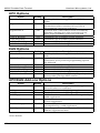
Code 39 Options
Option
Decoder
Full ASCII
Check Digit
Setting
*On
*Off
*Off
Send Check
Concatenate
*Off
*Off
Description
Enables/disables reading Code 39 bar codes.
Enables/disables reading Full ASCII extension of Code 39.
Enables/disables mod 43 check digit. (Code 39 bar codes
only containing a valid check digit can be read.)
Transmits mod 43 check digit with bar code data.
Enables/disables concatenate mode (see definition below.)
Note: The concatenate mode allows the M5000 PDT to accumulate multiple Code 39 bar codes in
the buffer and send them to the computer as though a single bar code. When a Code 39 bar code
containing a leading space is read, the M5000 PDT beeps twice and buffers the data without
transmission. This process continues until a Code 39 bar code without a leading space is read or
128 characters are buffered. A Code 39 bar code that only contains dashes can clear the buffer.
22
M5000 Portable Data Terminal
American Microsystems, Ltd.
UPC Options
Option
Decoder
Setting
*On
Expand UPCE
*Off
Expand UPCA
*Off
*UPCA #System
*UPCE #System
*UPCA Check Digit
*UPCE Check Digit
*On
*On
*On
*On
Description
Enables/disables reading UPC-A & UPC-E bar
codes.
Converts UPC-E bar codes to UPC-A before
transmission; after conversion (if on), UPC-A
programming options are followed.
Converts UPC-A bar codes to EAN-13 format by
inserting a leading zero; after conversion (if on),
EAN-13 programming options are followed.
Transmits UPC-A number system character.
Transmits UPC-E number system character.
Transmits UPC-A check digit character.
Transmits UPC-E check digit character.
EAN Options
Option
*Decoder
Setting
*On
EAN8 Zero Fill
*Off
*EAN13 Country Code
*EAN8 Country Code
*EAN13 Check Digit
*EAN8 Check Digit
ISBN Number Convert
*On
*On
*On
*On
*Off
Description
Enables/disables reading EAN-8 & EAN-13 bar
codes.
Adds five leading zeros to EAN-8 bar codes; after
conversion, (if on), EAN-13 programming options
are followed.
Transmits EAN-13 Country Code.
Transmits EAN-8 Country Code.
Transmits EAN-13 check digit character.
Transmits EAN-8 check digit character.
Converts 13 digit Bookland/EAN (978 prefix) to the
corresponding 10-digit ISBN number.
UPC/EAN Add-ons Options
Option
*Decoder
*2 Digit
*5 Digit
UPC Supplement
*On
*On
*Off
EAN Supplement
*Off
Bookland Supplement
*Off
Send Space
*Off
*Notes default
23
Setting
*Off
Description
Enables/disables reading UPC & EAN supplement
bar code unless on is selected.
Enables/disables reading 2 digit supplements.
Enables/disables reading 5 digit supplements.
UPC bar codes are not read unless accompanied by a
valid supplement.
EAN bar codes are not read unless accompanied by
a valid supplement.
Bookland/EAN bar codes are not read unless
accompanied by a valid supplement.
Inserts a space between the standard bar code data
and the supplemental data.
American Microsystems, Ltd.
M5000 Portable Data Terminal
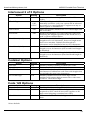
Interleaved 2 of 5 Options
Option
Decoder
Setting
*On
Check Digit
*None
USS
OPCC
Send Check
*Off
Fixed Size
*Off
Fixed Size 1 (6-60)
*6
Fixed Size 2 (0-60)
*0
Fixed Size 3 (0-60)
*0
Description
Enables/disables reading Interleaved 2 of 5 bar
codes.
USS Check Digit and OPCC Check Digit are
mutually exclusive (only one option can be selected
at a time). You can toggle left or right arrow key to
select option on M5000 PDT.
Does not transmit Interleaved 2 of 5 check digit with
bar code data.
Reads fixed length I 2 of 5 bar code bar codes only
matching the lengths specified in the fixed size 1, 2
and 3 options defined below.
Sets the first valid fixed length for I 2 of 5. Valid
lengths are 2 to 60 characters, however length must
be an even number. Default fixed length is 6
characters and is disabled when set to 0 characters.
Sets the second valid fixed length for I 2 of 5. Default
length is set to 0 characters (the second fixed length
is disabled).
Sets the third valid fixed length for I 2 of 5. Default
length is set to 0 characters (the third fixed length is
disabled).
Codabar Options
Option
Decoder
Start/Stop
CLSI Format
Setting
*On
*Off
*Off
CLSI Chk Digit
*Off
Description
Enables/disables reading Codabar bar codes.
Transmits the Codabar start/stop characters.
A blank after the first, fifth and tenth characters of a
14-character Codabar bar code. Bar code length does
not include the start/stop characters.
Enables/disables the CLSI check digit. When
enabled, all fourteen digit numeric bar codes must
contain a valid check digit.
Code 128 Options
Option
Decoder
UCC Verify
*Send Mod 10
Setting
*On
*Off
*On
Description
Enables/disables reading Code 128 bar codes.
Check for a valid mod 10 check digit. Mod 10 is not
required on UCC mod 10 bar codes (applies to 20digit serial shipping container bar codes).
Transmits the mod 10-check digit with the bar code
data.
*Notes default
24
M5000 Portable Data Terminal
American Microsystems, Ltd.
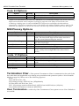
Code 93 Options
Option
Decoder
Concatenate
Setting
*On
*Off
Description
Enables/disables reading Code 93 bar codes.
Enables/disables concatenate mode.
Note: The concatenate mode allows the M5000 PDT to accumulate multiple Code 93 bar codes in the
buffer and sends them to the computer as though a single bar code. When a Code 93 bar code
containing a leading space is read, the M5000 PDT beeps twice and buffers the data without
transmission. This process continues until a Code 93 bar code without a leading space is read or 128
characters are buffered. A Code 93 bar code bar code that only contains dashes will clear the buffer.
MSI/Plessey Options
Option
Decoder
2nd Check Digit
Setting
*Off
*Off
Mod 11 Check (Digit)
*Off
Send Check 1
Send Check 2
ISBN
*Off
*Off
*Off
Description
Enables/disables reading MSI/Plessey bar codes.
Two valid check digits are required for each bar
code. The first check digit can be either mod 10 or
11, the second must always be mod 10.
Determines whether mod 11 or mod 10 is used as
the first check digit.
Transmits the first check digit.
Transmits the second check digit.
Enables/disables reading Modified Plessey ISBN bar
codes. (Only eleven-digit ISBN bar codes can be
read.)
Code 11 Options
Option
Decoder
2nd Chk Digit
Send Check 1
Send Check 2
Setting
*Off
*Off
*Off
*Off
Description
Enables/disables reading Code 11 bar codes.
Two valid check digits are required for each bar
code.
Transmits the first check digit.
Transmits the second check digit.
*Notes default
Termination Char—The optional Termination Char is transmitted at the end of the
bar code data and applicable only during non-portable mode operation (refer to Non-Portable
Mode on page 31). Select one of the following options:
None
Tab (ASCII 09; hex /09)
CR (carriage return, ASCII 13; hex /0D)(default)
LF (line feed, ASCII 10; hex /0A)
CR + LF (carriage return and line feed, ASCII 13 and ASCII 10; hex /0D/0A)
User defined termination character (00H-F9H).
User Termination—valid only if the Termination Char option is set to User. Default is
set to 00H.
25
American Microsystems, Ltd.
M5000 Portable Data Terminal
Termination Override—if a control character or special character (Func, arrow, etc.) is
embedded in the bar code data, the preamble, postamble and termination character is not
transmitted. Default is set to off.
Preamble
—is a set of user-defined characters and transmitted at the beginning of the bar
code data. To define the preamble, enter ASCII characters. This option is active only during nonportable mode. This field can include 0-32 characters, alpha, numeric and all ASCII characters.
Preamble Send Delay—is an option that specifies the amount of delay occurring
after the bar code preamble is transmitted. The delay period is programmable from 0.0 to 9.9
seconds, default is 0.0 seconds.
Postamble
—is a set of user defined characters and transmitted at the end of the bar
code data. To define the postamble, enter ASCII characters. This option is active only during
non-portable mode. This field can include 0-32 characters, alpha, numeric and all ASCII
characters
Postamble Send Delay—is an option that specifies the amount of delay occurring
after the bar code preamble is transmitted. The delay period is programmable from 0.0 to 9.9
seconds, default is 0.0 seconds.
Bar Code Edit—the editing option must be checked for editing options to be
operational.
Editing—enables bar code editing.
Space Strip—refers to bar code leading and trailing spaces to be stripped or removed
from the data. (Editing must be on.)
Leading Strip—refers to the number of bar code characters (0-30) to be stripped or
removed from the beginning of the bar code data.
Trailing Strip—refers to the number of bar code characters (0-30) to be stripped or
removed from the end of the bar code data.
Note: If the total number of strip characters (leading and trailing) is greater than the number of
characters in the bar code, no characters are stripped.
Code—editing can either apply to all or one bar code type. The default is All bar code types.
Bar Code Beeper
—when you scan a bar code the M5000 PDT emits a beep. The
following settings allow you to set the tone and length of the beep.
Tone—sets the volume of the beep. Select one of the following options:
None
Low
Medium (default)
High
Length—sets the length of the beep. Select one of the following options:
Shortest
Short (default)
Long
Longest
26
M5000 Portable Data Terminal
American Microsystems, Ltd.
Comm. Setup
Refer to Communications Setup in the previous section.
Laser/CCD Options
Mode—select one of the following options by using the left or right arrow:
Triggera trigger pull activates the laser that remains on until the trigger is released, a valid
decode occurs or a laser/CCD timeout is reached. (default)
Pulsea trigger pull activates the laser that remains on until a valid decode occurs or a
laser/CCD timeout is reached.
Continuousa trigger pull activates the laser that remains on while the trigger is pressed or a
valid decode occurs before the laser/CCD timeout is reached.
Blinka trigger pull activates the laser that remains on for a period equal to the laser/CCD
timeout after a valid decode occurs. The laser blinks 250ms on and 250ms off. Blink mode does
not operate properly for lasers that employ thermal shutdown.
Timeoutif the laser or CCD does not read a bar code within the designated time period,
the device turns off. Select off or a 1-9 second delay. (If the option is set to off, it overrides this
safety feature.) (The default is a three-second timeout.)
Read Delay—this option sets the delay period between successive reads of the same bar
code. This allows the removal of the bar code from the scan field without multiple reads. Select
one of the following options:
0.0
1.0
(no delay) – 9.9 seconds (incremented in tenths of a second)
second (default)
Other Options
Bar Code ID—transmits the bar code identifier character at the beginning of the bar code
data. A space is included between the ID character and the bar code data. Choose Off or On to
activate this option. Default is set to On.
Duplicate Reads—enables reading the same bar code multiple times. (Default is set to
on.)
Read Verify #—value from 0 to 9 denoting number of rereads of same bar code before
accepting it as valid data. (Default is 0.)
F1—F10 Keys—enables reading of function keys in place of ASCII characters. (Default
is set to on.)
Special Keys—enables reading of special keys in place of ASCII characters. (Default is
set to on.)
27
American Microsystems, Ltd.
M5000 Portable Data Terminal
Other Setup
Timeout—sets the amount of time (1-99 minutes) the M5000 PDT remains on after the last
activity, however, it is disabled while operating in keyboard wedge mode. Option is set to five
minutes by default.
Password—to access the Setup mode, a password must be entered. The fixed password
(OK) cannot be changed. Option is off by default.
Auto Input—select Auto Input and the M5000 PDT automatically loads the first program
in memory when Input is selected. If a data file or multiple data files exist for the active
program, the M5000 PDT uses the first file created for that program. If a data file for the
program does not exist, the M5000 PDT creates a filename FILE#1. Option is off by default.
Auto Save—automatically saves the data file when you exit Input. Option is unchecked
by default.
View Delay—sets the duration of the displayed characters for bar code data and lookup
file entries. Default is set to 0.5s.
Overwrite—bar code data automatically overwrites the contents of the current input.
Option is on by default.
Halt on Err—halts when an error occurs during operation and disables the bar code
reader input. The appropriate error message is displayed until a key is pressed. Option is off by
default.
Wedge Keypad—enables or disables keypad output during any non-portable mode
operation. Option is off by default.
Keypad Beep—enables or disables Keypad Beep when a key is pressed. Option is on by
default.
Left Trigger—sets the M5000 PDT left trigger to the following mode using the left or
right arrow:
None—trigger is ignored.
Alpha—trigger function is the same as pressing the alpha key on the keyboard.
Laser—trigger function is the same as pressing the trigger on the laser. (default)
Right Trigger—sets the M5000 PDT right trigger to the following mode using the left or
right arrow:
None—trigger is ignored.
Alpha—trigger function is the same as pressing the alpha key on the keyboard.
Laser—trigger function is the same as pressing the trigger on the laser. (default)
Reset Setups—resets Setup options to the default settings. You are prompted to Reset
All Setups to Default? (No).
28
M5000 Portable Data Terminal
American Microsystems, Ltd.
Non-Portable Mode
Once the Non-port mode is selected from the Main Menu, the interface mode is automatically
determined based on your cable connection. It may be necessary to reselect non-port mode on the
Main Menu if cable changes are made during non-port mode. Two ways in which the M5000 PDT
relays bar code data to the host computer are keyboard wedge and RS232 serial.
Keyboard Wedge transmits bar code data to the host computer via a hardware device called the
M5100 Keyboard Wedge. This device is connected in-line to the host computer’s keyboard and sends
data to the host computer as if it were typed from the host keyboard.
RS-232 Serial transmits bar code data to the host computer’s serial port. This mode uses the protocol
and serial parameters from the Communications Setup option. (Refer to Comm. Setup page 21.)
Upgrade Flash
— Previously, if you wanted to update portable bar code reader
firmware, you would physically open the scanner and replace the EPROM and in some cases is
costly, time consuming and complicated. Today you can use a much easier method. The flash
memory can be easily updated using our communications interface cable, IBM compatible computer
and a software file.
You can download amended firmware only if American Microsystems Technical Support has
instructed you to upgrade the firmware on your M5000 PDT.
Warning! When this option is selected the M5000 PDT warns you that you
will lose all program files and data files if you proceed. You may wish to
validate proper xmodem communication through your serial port.
1.
Connect the communications interface cable (RS-232) into an available RS-232 port on your
computer.
2.
Connect the opposite end of the communications interface cable to the RJ45 10-pin connector on
the bottom of the M5000 PDT.
3.
On your M5000 PDT from the Main Menu select Upgrade Flash (U). You will be prompted by
the confirmation message, All Data & Programs Will Be Lost! Are You Sure? Choose Y or toggle
this selection to (yes). The M5000 PDT is now waiting for connection.
4.
To access the M5000 Programmer software from WIN95 taskbar, click Start, select Programs,
select M5000 Utilities and select M5000 Programmer.
5.
Under the Communications menu, select Upgrade Flash. The communications submenu is then
brought up on the screen and file selection dialog box will prompt you to select a UPG file
(image.upg).
6.
7.
Press ok to select UPG file.
The Communications dialog will again appear press Send to upload flash upgrade.
Once the file has been transmitted, the flash upgrade is complete. The M5000 PDT automatically
returns you to the Main Menu. The options will be reset to factory defaults.
Browse—allows you to select the flash file you want to send.
Send/Exit—after you select a file to send, press the Send button. While the M5000
Programmer is sending the file, the button changes to Cancel, allowing you to abort the
transmission.
29
American Microsystems, Ltd.
M5000 Portable Data Terminal
Using the M5005 Integrated Laser Scanner
The M5500 PDT consists of the American Microsystems M5000
Portable Data Terminal integrated with our new M5005 Integrated
Laser Scanner. These two units combine to form a powerful and
easy-to-use data collection system.
The M5500 provides all the features of the M5000 PDT together
with the convenience of one-handed, portable scanning and the
speed and accuracy of laser input. The M5500 PDT can be easily
adapted for right- or left-hand use. The unit has two triggers that
allow you to scan bar code data with your right or left hand. It can
be positioned in your hand so that you can manually enter data
and/or scan bar code labels as desired. (Refer to How to Scan &
Enter Data on the M5500 PDT.)
Included with the M5500 PDT is a communications program that
makes uploading data from the RS-232 serial port directly into
word processors, text editors, point-of-sale programs, inventory
programs and other application programs quick and easy. Data
can also be uploaded as an ASCII file. The M5500 PDT also comes
with an easy-to-use Windows compatible program generator. The
M5500 PDT programming software allows you to generate
customer programs or use our program templates to configure a
program to meet your specific needs.
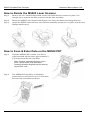
How to Assemble the M5005 Laser Scanner
Step 1:
Remove the two small Phillips-head screws that hold the black plastic retainer clip in place
located on top of the M5000 PDT; then remove the retainer clip.
Step 2:
Attach the M5005 Laser Scanner base assembly to the top of the M5000 PDT by connecting
the two 9-pin connectors. (The base assembly stays mounted to the M5000 PDT and
provides easy removal when you want to change from right-hand operation to left.)
Step 3:
Select either left-hand or right-hand position, and secure the M5005 Laser Scanner by
fastening it to the M5000 PDT with the two long Phillips-head screws provided.
Note: These two screws cannot be used later to secure the laser scanner in place.
30
M5000 Portable Data Terminal
American Microsystems, Ltd.
How to Rotate the M5005 Laser Scanner
Step 1:
Remove the two small Phillips-head screws that hold the laser scanner in place. Lift
straight up to separate the laser scanner from the base assembly.
Step 2:
Rotate the M5005 Laser Scanner 180 degrees so it faces the desired scanning direction.
Step 3:
Attach the M5005 Laser Scanner onto the base assembly and secure it in place with the two
Phillips-head screws.
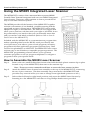
How to Scan & Enter Data on the M5500 PDT
Step 1:
Hold the M5500 PDT in either your left or
right hand and aim the laser approximately 3
to 6 inches from the bar code label.
Note: Typical scanning distance varies
from 3 to 22 inches. The maximum
scanning distance depends on the density
of your bar code.
Step 2:
31
The M5500 PDT should be comfortably
positioned in your hand for you to enter data
and scan bar code labels as shown.
American Microsystems, Ltd.
M5000 Portable Data Terminal
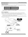
Specifications
The M5005 Integrated Laser Scanner uses a low-power visible laser diode. Although momentary
exposure to a CDRH Class II laser is not known to be harmful, avoid staring directly into the light
beam, extended exposure may cause damage to your eyes.
Light Source
Laser Output Power
Scan Rate
Laser Class
630-680 nm laser diode
1.0 mW maximum
35 + 5 scans per second
CDRH Class II
Caution: Changes or modifications not expressly approved by American Microsystems, Ltd.
could void the user's authority to operate this equipment.
FCC Compliance
This device complies with Part 15 of the FCC Rules. Operation is subject to the following two
conditions: 1) this device may not cause harmful interference, and 2) this device must accept any
interference received, including interference that may cause undesired operation.
Caution: Use of controls, adjustments, or performance of procedures other than those specified
herein may result in hazardous visible laser light exposure.
The following Certification/Identification labels are attached to the M5005 Integrated Laser Scanner
in compliance with FCC Rules.
32
M5000 Portable Data Terminal
American Microsystems, Ltd.
System Warnings
Warning Message
Input Has Data
Cannot Overwrite
Input Is Full
Cannot Insert Char
Input Not Found In
Lookup Table
Input Not Found Accept
Anyway (Yes)
No Editing Allowed
Bar Code Is Too
Long/Short For Input
Input Is Already On File
No Programs Exist
Out Of Memory
No Data Files Found
Duplicate Filename
Complete Record Before
Searching
Complete Record Before
Inserting
*END OF FILE*
No More Inputs
Cannot Insert Before a
Header
Input Not Satisfied
Program Already
Loaded in RAM
Invalid Record Number
Lookup File Is Not In
Memory
Almost Out Of Memory
New Record Has Been
Inserted
33
Warning Description
Reading a bar code into a data input field and the Bar Code
Overwrite option is off.
During data input, maximum input size specification has been
reached and will not allow additional characters to be inserted.
Data entered in a lookup field does not match and a custom error
message is not defined.
Data entered in a lookup field does not match and the option,
Accept Mismatches is on.
User cannot edit a No Edit field.
A bar code read into the current input field is too long/short and
not allowed by min/max specifications.
A duplicate input has been detected when the option NO
Duplicates Allowed is enabled.
No programs have been created; either a built-in or custom
program must be loaded.
Accessing Input mode with less than 256 bytes of free memory or
receiving a file that exceeds available memory.
Accessing Input mode and selecting a program with the option
Receive Data Files only and that program has no data files.
User tries to enter a data file name and that name is already used
by another data file.
User tries to search from within data input before the current
record is satisfied.
User tries to insert a record from within data input before the
current record is satisfied.
End of defined program inputs has been reached.
User tries to insert a record during data input while accessing a
header record.
User tries to advance to a new record before the current record is
satisfied.
User tries to load a built-in copy of program P1-P6 and it is already
loaded in RAM.
Using the Goto Record option, user tries to enter an invalid record
number.
The lookup file specified in the program has not been loaded into
memory.
User tries to access data input with less than 1K of memory
remaining.
User inserts a new record during data input.
American Microsystems, Ltd.
Warning Message
Invalid
Bar Code Type
No Data Files Found
Transmit/Receive
Aborted By User
Receive Error
Checksum Error
No Carrier
Invalid ASCII File
Invalid System File
Invalid Data File
File Name Error
Invalid Data File
Prog Name Error
Program Not Defined
Invalid Data File
File ID Error
Timeout Error
Transmit Error
No Lookup Files Found
INVALID PASSWORD
Press Any Key
No Match Found
No Programs Exist
All Programs Have Data
Files
Recall Buffer is Empty
Recall Data is Too
Short/Long for Input
Recall Data Not
Valid For Input
Invalid Bar Code Data
For Input
A Power Fail Has
Occurred
Battery Low
Change Battery Soon
M5000 Portable Data Terminal
Warning Description
Bar code type does not match current input field specifications.
When attempting to upload data, no data files are found.
User presses a key causing an abort.
Indicates the received communication aborted with an error.
An invalid checksum is detected in a system file.
Communications carrier was lost during modem transfer.
ASCII file is too long/short or invalid to receive.
System file is too long/short or invalid to receive.
Data file name was either blank or more than 8 characters.
Program file name was either blank or more than 8 characters.
Program specified in the data file is not found or programs do not
exist to SEND.
Invalid file ID for ASCII file. Note: ID must be (D) data or (L)
lookup.
No response from sender/receiver; timeout occurs.
Indicates the transmitted communication aborted with an error.
User tries to Send or Erase lookup files when there are none in
memory.
User tries using an invalid password when trying to access Setup
with the Password option on.
After conducting a Find, no matches are found.
User tries to erase a program where none exist.
User tries to erase programs and all programs have data files
included. Data files must be erased first.
Using the Recall option before data input has been stored.
Data recalled into the current input field is too long/short and not
allowed by min/max specifications.
Recall data does not match the current data input specifications.
Bar code data does not match the current data input specifications.
Power to the M5000 PDT has failed or a checksum failure caused
the M5000 PDT to abort.
Low battery detected; replace with AAA batteries.
34
M5000 Portable Data Terminal
American Microsystems, Ltd.
Troubleshooting Guide
Problem
When the power button is
pressed, the M5000 PDT does not
turn on.
Keyboard locks-up
Bar codes will not scan.
Losing data during serial
communications
Difficulty scanning bar codes
while using laser or CCD
The M5000 PDT turns off
automatically
When entering data to assign the
file or program a name, I cannot
enter special characters.
The M5000 PDT beeps if I try to
enter more than 8 characters for a
filename.
Why does the cursor blink with a
solid block and sometimes with
an underline?
I keep getting a Keyboard Wedge
Error.
When I upgraded the flash
memory, all my data was lost.
A modem adapter is connected
between the communications
interface cable and the modem
and I still cannot use my modem.
When I received a new clone file,
all my previous setup menu
selections disappeared.
35
Solution
Check the batteries; make sure they are installed in the
correct position.
Check all cable connections, if applicable.
Check Wedge Programmer settings.
Check the bar code setup to verify the bar code to be
scanned is enabled in the M5000 PDT or your program.
Baud rate could be set too fast; adjust to a slower rate
or check protocol for correct setting.
Laser or CCD could be too close or too far away from
the bar code or the scanning angle is incorrect. Scan
within the guidelines specified for your type of
scanner.
To conserve battery power, the M5000 PDT has a timeout feature with default 5-minutes. Power the M5000
PDT on and it resumes in the same menu you were in
before it timed-out.
The file name and the program name are programmed
to accept only alphanumeric characters and not special
characters such as: , ?, #, etc.
When entering a file name, only eight characters are
accepted.
When the cursor blinks with a solid block, alpha mode
is in use; when the cursor blinks with an underline,
standard mode is in use.
Keyboard Wedge is not connected correctly—check
your connections.
When this option is selected, the M5000 PDT warns
you that you will lose all program and data files if you
proceed.
A 9 to 25 pin adapter may also be required to complete
the connection.
The M5000 PDT erases all previous setup menu
selections, programs, lookup files and data files.
American Microsystems, Ltd.
M5000 Portable Data Terminal
Non-ASCII Special Characters
Hex Code
ASCII
/8C
/8D
/8E
/8F
/90
/91
alt on
alt off
ctrl on
ctrl off
shift on
shift off
Note: Keys must be used in pairs, for example, a desired ALT must be transmitted as ALT ON, A, ALT
OFF.
Hex Code
/92
/93
/94
/95
/96
/97
/98
/99
/9A
/9B
Function Key
Hex Code
Function Key
page up
page down
home
end
delete
insert
left arrow
right arrow
up arrow
down arrow
/F1
/F2
/F3
/F4
/F5
/F6
/F7
/F8
/F9
/F0
1
2
3
4
5
6
7
8
9
10
Non-ASCII Delay Character Values
Hex Code
Delay (sec)
/D1
/D2
/D3
/D4
/D5
/D6
/D7
/D8
/D9
1
2
3
4
5
6
7
8
9
Note: The characters above are valid for use in SOF text, EOF text, SOT text, EOT text, preamble
(prefix) and postamble (suffix) fields.
36
M5000 Portable Data Terminal
American Microsystems, Ltd.
Special and Function Keys for Bar Codes
The following characters are transmitted during non-portable (keyboard and RS-232) mode with
Special Keys and Function Keys enabled.
DEC
1
2
3
4
5
6
7
11
12
14
15
16
17
18
19
20
21
22
23
24
25
26
28
29
30
31
37
HEX
CODE
/01
/02
/03
/04
/05
/06
/07
/0B
/0C
/0E
/OF
/10
/11
/12
/13
/14
/15
/16
/17
/18
/19
/1A
/1C
/1D
/1E
/1F
ASCII
SOH
STX
ETX
EOT
ENQ
ACK
BEL
VT
FF
SO
SI
DLE
DC1
DC2
DC3
DC4
NAK
SYN
ETB
CAN
EM
SUB
FS
GS
RS
US
OUTPUT
CHARACTER
LEFT ARROW
RIGHT ARROW
UP ARROW
DOWN ARROW
HOME
END
DEL
PAGE UP
PAGE DOWN
SHIFT ON
SHIFT OFF
INS
F1
F2
F3
F4
F5
F6
F7
F8
F9
F10
CTRL ON
CTRL OFF
ALT ON
ALT OFF
SPECIAL
KEYS
ENABLED
X
X
X
X
X
X
X
X
X
X
X
X
FUNCTION
KEYS
ENABLED
X
X
X
X
X
X
X
X
X
X
X
X
X
X
American Microsystems, Ltd.
M5000 Portable Data Terminal
ASCII Character Chart
DEC
0
1
2
3
4
5
6
7
8
9
10
11
12
13
14
15
16
17
18
19
20
21
22
23
24
25
26
27
28
29
30
31
32
33
34
35
36
37
38
39
40
41
42
43
44
45
46
47
48
HEX
CODE
/00
/01
/02
/03
/04
/05
/06
/07
/08
/09
/0A
/0B
/0C
/0D
/0E
/0F
/10
/11
/12
/13
/14
/15
/16
/17
/18
/19
/1A
/1B
/1C
/1D
/1E
/1F
/20
/21
/22
/23
/24
/25
/26
/27
/28
/29
/2A
/2B
/2C
/2D
/2E
/2F
/30
ASCII
NUL (CTRL 2)
SOH (CTRL A)
STX (CTRL B)
ETX (CTRL C)
EOT (CTRL D)
ENQ (CTRL E)
ACK (CTRL F)
BEL (CTRL G)
BS (CTRL H)
HT (CTRL I)
LF (CTRL J)
VT (CTRL K)
FF (CTRL L)
CR (CTRL M)
SO (CTRL N
SI (CTRL O)
DLE (CTRL P)
DC1 (CTRL Q)
DC2 (CTRL R)
DC3 (CTRL S)
DC4 (CTRL T)
NAK (CTRL U)
SYN (CTRL V)
ETB (CTRL W)
CAN (CTRL X)
EM (CTRL Y)
SUB (CTRL Z)
ESC (CTRL [)
FS (CTRL \)
GS (CTRL ])
RS (CTRL 6)
US (CTRL -)
SP
!
"
#
$
%
&
'
(
)
*
+
,
.
/
0
DEC
49
50
51
52
53
54
55
56
57
58
59
60
61
62
63
64
65
66
67
68
69
70
71
72
73
74
75
76
77
78
79
80
81
82
83
84
85
86
87
88
89
90
91
92
93
94
95
96
97
HEX
CODE
/31
/32
/33
/34
/35
/36
/37
/38
/39
/3A
/3B
/3C
/3D
/3E
/3F
/40
/41
/42
/43
/44
/45
/46
/47
/48
/49
/4A
/4B
/4C
/4D
/4E
/4F
/50
/51
/52
/53
/54
/55
/56
/57
/58
/59
/5A
/5B
/5C
/5D
/5E
/5F
/60
/61
ASCII
1
2
3
4
5
6
7
8
9
:
;
<
=
>
?
@
A
B
C
D
E
F
G
H
I
J
K
L
M
N
O
P
Q
R
S
T
U
V
W
X
Y
Z
[
\
]
^
_
`
a
DEC
98
99
100
101
102
103
104
105
106
107
108
109
110
111
112
113
114
115
116
117
118
119
120
121
122
123
124
125
126
127
HEX
CODE
/62
/63
/64
/65
/66
/67
/68
/69
/6A
/6B
/6C
/6D
/6E
/6F
/70
/71
/72
/73
/74
/75
/76
/77
/78
/79
/7A
/7B
/7C
/7D
/7E
/7F
ASCII
b
c
d
e
f
g
h
i
j
k
l
m
n
o
p
q
r
s
t
u
v
w
x
y
z
{
¦
}
~
DEL
38