1
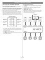
FreeSpace® 4400 Business Music System
OWNER’S GUIDE
Safety Information
Please read this owner’s guide
Please take the time to follow the instructions in this owner’s guide carefully. It will help you set up and operate
your system properly and enjoy all of its advanced features. Please save this owner’s guide for future reference.
WARNING: To reduce the risk of fire or electrical shock, do not expose the product to rain or moisture.
WARNING: The apparatus shall not be exposed to dripping or splashing, and objects filled with liquids, such as vases,
shall not be placed on the apparatus. As with any electronic products, use care not to spill liquids into any part of the
system. Liquids can cause a failure and/or a fire hazard.
The lightning flash with arrowhead symbol within an equilateral triangle alerts the user to the presence of
uninsulated, dangerous voltage within the system enclosure that may be of sufficient magnitude to
constitute a risk of electrical shock.
The exclamation point within an equilateral triangle, as marked on the system, is intended to alert the
user to the presence of important operating and maintenance instructions in this owner’s guide.
CAUTION: Make no modification to the system or accessories. Unauthorized alterations may compromise safety,
regulatory compliance, and system performance.
CAUTION: This product shall be connected to a mains socket outlet with a protective earthing connection.
This product conforms to the EMC Directive 89/336/EEC and to the Low Voltage
Directive 73/23/EEC. The complete Declaration of Conformity can be found on
www.Bose.com/static/compliance/index.html.
Note: Where the mains plug or appliance coupler is used as the disconnect device, such disconnect device shall
remain readily operable.
Note: The product must be used indoors. It is neither designed nor tested for use outdoors, in recreation vehicles, or
on boats.
Note: Provide an earth connection before the main plug is connected to the mains.
ii
Important Safety Information
Caution marks on the product
15. To prevent risk of fire or electric shock, avoid overloading wall
outlets, extension cords, or integral convenience receptacles.
16. Do not let objects or liquids enter the product – as they may
touch dangerous voltage points or short-out parts that could result
in a fire or electric shock.
17. See product enclosure for safety related markings.
18. No naked flame sources, such as lighted candles, should be
placed on the apparatus.
These CAUTION marks are located on the back of the product.
The lightning flash with arrowhead symbol, within an equilateral
triangle, is intended to alert the user to the presence of uninsulated dangerous voltage within the system enclosure that may
be of sufficient magnitude to constitute a risk of electric shock.
The exclamation point within an equilateral triangle, as marked
on the system, is intended to alert the user to the presence of
important operating and maintenance instructions in this
owner’s guide.
WARNING: To reduce the risk of fire or electric shock, do not
expose the amplifier to rain or moisture.
Important safety instructions
1.
2.
3.
4.
5.
6.
7.
8.
9.
10.
11.
12.
13.
14.
Information about products that
generate electrical noise
Read these instructions.
Keep these instructions
Heed all warnings.
Follow all instructions.
Do not use this apparatus near water.
Clean only with a dry cloth.
Do not block any ventilation openings. Install in accordance
with the manufacturer’s instructions – To ensure reliable operation of the product and to protect it from overheating, put the product in a position and location that will not interfere with its proper
ventilation.
Do not install near any heat sources, such as radiators, heat
registers, stoves, or other apparatus (including amplifiers) that
produce heat.
Do not defeat the safety purpose of the polarized or groundingtype plug. A polarized plug has two blades with one wider than
the other. A grounding-type plug has two blades and a third
grounding prong. The wider blade or third prong are provided
for your safety. If the provided plug does not fit into your outlet,
consult an electrician for replacement of the obsolete outlet.
Protect the power cord from being walked on or pinched, particularly at plugs, convenience receptacles, and the point where
they exit from the apparatus.
Only use attachments/accessories specified by the
manufacturer.
Use only with the cart, stand, tripod, bracket, or
table specified by the manufacturer or sold with the
apparatus. When a cart is used, use caution when
moving the cart/apparatus combination to avoid
injury from tip-over.
Unplug this apparatus during lightning storms or when unused
for long periods of time.
Refer all servicing to qualified service personnel. Servicing is
required when the apparatus has been damaged in any way
such as power-supply cord or plug is damaged; liquid has been
spilled or objects have fallen into the apparatus; the apparatus
has been exposed to rain or moisture, does not operate normally, or has been dropped.
If applicable, this equipment has been tested and found to comply with the limits for a Class A digital device, pursuant to Part 15
of the FCC rules. These limits are designed to provide reasonable
protection against harmful interference in a residential installation. This equipment generates, uses, and can radiate radio frequency energy and, if not installed and used in accordance with
the instructions, may cause harmful interference to radio communications. However, this is no guarantee that interference will not
occur in a particular installation. If this equipment does cause
harmful interference to radio or television reception, which can be
determined by turning the equipment off and on, you are encouraged to try to correct the interference by one or more of the following measures:
• Reorient or relocate the receiving antenna.
• Increase the separation between the equipment and receiver.
• Connect the equipment to an outlet on a different circuit than
the one to which the receiver is connected.
• Consult the dealer or an experienced radio/TV technician for
help.
Note: Unauthorized modification of the receiver or radio remote
control could void the user’s authority to operate this equipment.
This product complies with the Canadian ICES-003 Class B
specifications.
The information furnished in this user’s guide does not include all
of the details of design, production, or variations of the equipment. Nor does it cover every possible situation which may arise
during installation, operation, or maintenance. If you need assistance beyond the scope of this user’s guide, please contact our
Customer Service department. See “Customer support” on
page 60.
iii
Contents
1.0 FreeSpace® 4400 Introduction . . . . . . . . . . . . . . . . . . .
1.1 The Bose® FreeSpace® 4400
Business Music System . . . . . . . . . . . . . . . . . .
1.2 FreeSpace 4400 system accessories . . . . . . . . . .
1.3 FreeSpace 4400 Installer™
software . . . . . . . . . . . . . . . . . . . . . . . . . . . . . . .
2.0 Designing with the FreeSpace® 4400 System . . . . . . .
2.1 Introduction . . . . . . . . . . . . . . . . . . . . . . . . . . . . . .
2.2 Basic design steps . . . . . . . . . . . . . . . . . . . . . . . . .
2.2.1 Step 1 – Determine source routing . . . . . . . .
2.2.2 Step 2 – Determine Auto Volume
requirements . . . . . . . . . . . . . . . . . . . . . .
2.2.3 Step 3 – Determine volume control
requirements . . . . . . . . . . . . . . . . . . . . . .
2.2.4 Step 4 – Determine the loudspeaker
requirements . . . . . . . . . . . . . . . . . . . . . .
2.2.5 Step 5 – Determine the FreeSpace® 4400
requirements . . . . . . . . . . . . . . . . . . . . . .
2.3 Auto Volume layout examples . . . . . . . . . . . . . . . .
3.0 FreeSpace® 4400 Hardware Description . . . . . . . . . . .
3.1 Front panel . . . . . . . . . . . . . . . . . . . . . . . . . . . . . . .
3.1.1 Controls . . . . . . . . . . . . . . . . . . . . . . . . . . . . .
3.1.2 Indicators . . . . . . . . . . . . . . . . . . . . . . . . . . .
3.2 Rear panel . . . . . . . . . . . . . . . . . . . . . . . . . . . . . . .
3.2.1 System controls . . . . . . . . . . . . . . . . . . . . . .
3.2.2 Audio source inputs . . . . . . . . . . . . . . . . . . .
3.2.3 Amplifier outputs . . . . . . . . . . . . . . . . . . . . . .
3.2.4 AC power . . . . . . . . . . . . . . . . . . . . . . . . . . .
4.0 Hardware Installation . . . . . . . . . . . . . . . . . . . . . . . . . .
4.1 Introduction . . . . . . . . . . . . . . . . . . . . . . . . . . . . . .
4.2 Included accessories . . . . . . . . . . . . . . . . . . . . . . .
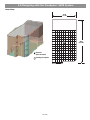
4.3 Placement guidelines . . . . . . . . . . . . . . . . . . . . . . .
4.4 Shelf mounting the FreeSpace 4400 system . . . . .
4.5 Rack mounting the FreeSpace 4400 system . . . . .
4.6 Installing accessories . . . . . . . . . . . . . . . . . . . . . . .
4.6.1 Sensing microphones . . . . . . . . . . . . . . . . . .
4.6.2 Auto volume microphone inputs . . . . . . . . . .
4.6.3 User interfaces . . . . . . . . . . . . . . . . . . . . . . .
4.6.4 User interface connections . . . . . . . . . . . . . .
4.7 System wiring . . . . . . . . . . . . . . . . . . . . . . . . . . . . .
4.7.1 Serial data communications . . . . . . . . . . . . .
4.7.2 Remote standby switch . . . . . . . . . . . . . . . .
4.7.3 LINE 1/LINE 2 source input . . . . . . . . . . . . . .
4.7.4 AUX MIC/LINE 3 source input . . . . . . . . . . . .
4.7.5 PAGE/MIC/LINE 4 source input . . . . . . . . . .
4.7.6 DIRECT IN/CONTROL source input . . . . . . .
4.7.7 Amplifier ZONE OUTPUT outputs . . . . . . . . .
4.7.8 Output voltage setting (70/100V) . . . . . . . . .
4.7.9 ZONE 4 LINE OUT output . . . . . . . . . . . . . . .
4.8 AC power connections . . . . . . . . . . . . . . . . . . . . . .
4.8.1 Fuse type . . . . . . . . . . . . . . . . . . . . . . . . . . . .
4.8.2 AC POWER connection . . . . . . . . . . . . . . . .
5.0 Using FreeSpace® 4400 Installer™ Software . . . . . . . .
5.1 Installing the software . . . . . . . . . . . . . . . . . . . . . .
5.2 Connecting to the FreeSpace 4400 system . . . . . .
5.2.1 No hardware detected . . . . . . . . . . . . . . . . .
5.2.2 Incompatible microcontroller code . . . . . . . .
5.2.3 Sample design files . . . . . . . . . . . . . . . . . . . .
5.3 The FreeSpace 4400 Installer™ software
user interface . . . . . . . . . . . . . . . . . . . . . . . . . . .
5.4 Set Up Hardware mode . . . . . . . . . . . . . . . . . . . . .
5.5 Set Up Schedule mode . . . . . . . . . . . . . . . . . . . . .
5.5.1 Setting the clock . . . . . . . . . . . . . . . . . . . . . .
5.5.2 Adding events . . . . . . . . . . . . . . . . . . . . . . . .
5.5.3 Viewing and changing event settings . . . . . .
5.5.4 Removing events from the list . . . . . . . . . . . .
5.6 Service Hardware mode . . . . . . . . . . . . . . . . . . . . .
2
2
2
3
4
4
4
4
4
7
7
8
9
12
12
12
12
13
13
13
13
13
14
14
14
14
14
15
16
16
16
16
18
19
19
19
20
20
21
21
22
22
23
23
23
23
24
24
24
26
26
26
27
29
30
31
31
32
32
33
III
6.0 FreeSpace® 4400 System Setup . . . . . . . . . . . . . . . . . .
6.1 Introduction . . . . . . . . . . . . . . . . . . . . . . . . . . . . . .
6.2 Connecting your PC to a FreeSpace 4400 system
6.3 System setup procedure . . . . . . . . . . . . . . . . . . . .
6.3.1 Output gain . . . . . . . . . . . . . . . . . . . . . . . . . .
6.3.2 Zone setup . . . . . . . . . . . . . . . . . . . . . . . . . .
6.3.3 Input gain . . . . . . . . . . . . . . . . . . . . . . . . . . . .
6.3.4 Source assign . . . . . . . . . . . . . . . . . . . . . . . .
6.3.5 Source EQ . . . . . . . . . . . . . . . . . . . . . . . . . . .
6.3.6 Page setup . . . . . . . . . . . . . . . . . . . . . . . . . .
6.3.7 Zone EQ . . . . . . . . . . . . . . . . . . . . . . . . . . . .
6.3.8 Dynamic EQ . . . . . . . . . . . . . . . . . . . . . . . . . .
6.3.9 Auto Volume . . . . . . . . . . . . . . . . . . . . . . . . .
7.0 User Interface Operation . . . . . . . . . . . . . . . . . . . . . . . .
7.1 Enabling keypad operation . . . . . . . . . . . . . . . . . . .
7.2 Turning the system on . . . . . . . . . . . . . . . . . . . . . .
7.3 AVM user interface operation . . . . . . . . . . . . . . . . .
7.4 Page user interface operation . . . . . . . . . . . . . . . .
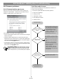
8.0 FreeSpace® 4400 System Troubleshooting . . . . . . . . .
8.1 Introduction . . . . . . . . . . . . . . . . . . . . . . . . . . . . . .
8.2 FreeSpace 4400 hardware
indicators . . . . . . . . . . . . . . . . . . . . . . . . . . . . . .
8.2.1 Normal operation . . . . . . . . . . . . . . . . . . . . . .
8.2.2 System fault . . . . . . . . . . . . . . . . . . . . . . . . . .
8.2.3 Amplifier fault . . . . . . . . . . . . . . . . . . . . . . . . .
8.2.4 Input clipping . . . . . . . . . . . . . . . . . . . . . . . . .
8.2.5 Direct input is active . . . . . . . . . . . . . . . . . . .
8.2.6 No STANDBY and SYSTEM indicators . . . . .
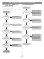
8.3 FreeSpace® 4400 system Error Log . . . . . . . . . . . .
8.3.1 Contents of the Error Log . . . . . . . . . . . . . . .
8.3.2 Hardware configuration . . . . . . . . . . . . . . . . .
8.3.3 Power-on self-test results . . . . . . . . . . . . . . .
8.3.4 Amplifier alarms . . . . . . . . . . . . . . . . . . . . . . .
8.3.5 Solving faults reported in the Error Log . . . .
8.4 Common problems . . . . . . . . . . . . . . . . . . . . . . . . .
8.4.1 Communications port error . . . . . . . . . . . . . .
8.4.2 No audio in zone . . . . . . . . . . . . . . . . . . . . . .
8.4.3 User interface keypads do not
operate correctly . . . . . . . . . . . . . . . . . . .
8.4.4 Bad sound in a zone . . . . . . . . . . . . . . . . . . .
8.4.5 Auto Volume does not calibrate . . . . . . . . . .
8.5 Customer support . . . . . . . . . . . . . . . . . . . . . . . . .
8.5.1 Technical assistance . . . . . . . . . . . . . . . . . . .
8.5.2 Reporting software bugs and issues . . . . . . .
9.0 Restoring FreeSpace® 4400 Microcontroller Code . . . .
34
34
34
35
35
36
37
39
40
40
42
43
43
49
49
49
49
51
52
52
10.0 Technical Specifications . . . . . . . . . . . . . . . . . . . . . . .
10.1 Power amplifier . . . . . . . . . . . . . . . . . . . . . . . . . . .
10.2 Digital signal processing . . . . . . . . . . . . . . . . . . .
10.3 Front panel indicators and control connections . .
10.4 Rear panel inputs, outputs, and controls . . . . . . .
10.5 FreeSpace 4400 system serial data commands .
64
64
64
64
64
64
52
52
52
53
54
54
54
55
55
55
55
56
57
58
58
58
59
59
60
60
60
60
62
1.0 FreeSpace® 4400 Introduction
1.1 The Bose® FreeSpace® 4400
Business Music System
• Serial Data Interface: RS-232 serial port for easy interfacing
to your PC
• Remote On/Off Input: Accepts a remote STANDBY switch
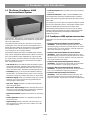
The integrated 400-watt power amplifier features a patented
power-sharing technology which dynamically allocates power to
each output.
For example, if you have a two-zone system that requires 5 watts
in Zone 1 and 395 watts in Zone 2, the FreeSpace 4400 system
electronics distributes the power based on those needs.
The FreeSpace 4400 system also includes an easy-to-replace
memory module, which holds the system configuration settings
and design file uploaded by the FreeSpace 4400 Installer™
software (see page 3).
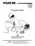
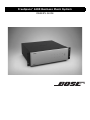
The FreeSpace® 4400 system is an integrated four-channel digital
signal processor and 400-watt power amplifier for 70/100V business music applications.
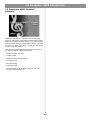
1.2 FreeSpace 4400 system accessories
Optional Bose accessories for the FreeSpace 4400 system are
available.
The FreeSpace 4400 system has a total of four source inputs,
including two Line In, one Mic/Line and one Page/Mic/Line, to
provide the inputs needed for most business music installations.
The system also has a direct input which can override the
sources playing on all four output channels.
• FreeSpace 4400 System AVM 1-Zone User Interface
(PC042351) A wall-mountable keypad that fits into a standard double-gang junction box. It provides buttons for volume
up/down control, 1-3 source selection, and mute or Auto Volume on/off controls for a single zone.
The FreeSpace 4400 system has four amplifier output channels
which can be configured for different zones. A Music on Hold output is also provided for simple integration into a phone system.
• FreeSpace 4400 System AVM 2-Zone User Interface
(PC042352) A wall-mountable keypad that fits into a standard double-gang junction box. It provides buttons for volume
up/down control, 1-3 source selection, and mute or Auto Volume on/off controls for two zones.
In a single chassis, it provides all of the processing and control
features required for one-to-four zone business music applications. These features include:
• Auto Volume: When used with the optional FreeSpace system
Auto Volume Sense Mic, FreeSpace 4400 system electronics
dynamically control the program level in each zone so your customers can always hear it, regardless of the background noise.
• Scheduling: Allows you to program the FreeSpace 4400 system electronics for automated on/off control, source changes,
and volume changes according to time of day or day of week.
• Multi-Zone Paging: Allows you to initiate a page from a single
keypad to one or more of the zones being powered by the
same FreeSpace 4400 system.
• FreeSpace 4400 System Auto Volume Mic Kit (U.S.)
(PC042354) One sensing microphone that can be mounted
as is or in a standard U.S. single-gang junction box.
• FreeSpace 4400 System Auto Volume Mic Kit (Euro)
(PC042355) One sensing microphone that can be mounted
as is or in a standard Euro single-gang junction box.
• FreeSpace 4400 System Page User Interface
(PC042353) A wall-mountable keypad that fits into a standard double-gang junction box. It provides buttons for 1-4
page zone selection, all page zones selection and initiate page.
• Opti-voice® Paging: Provides a smooth transition between
music and page signals.
• Opti-source® Input Leveling: Monitors the input level of up to
four sources and continually makes adjustments to maintain a
consistent volume level between different sources.
• Dynamic Equalization: Maintains tonal balance at all listening
levels.
• Room Equalization: Provides easy adjustment of tonal balance in each zone.
• Signal Routing: Meets the demands of most four-zone systems, allowing for an input source to be routed to any of the
four amplifier outputs.
2 of 66
1.0 FreeSpace® 4400 Introduction
1.3 FreeSpace 4400 Installer™
software
FreeSpace® 4400 Installer™ software is included with every
FreeSpace 4400 system. The FreeSpace 4400 Installer software
allows you to configure hardware devices such as the FreeSpace
4400 system. The FreeSpace 4400 Installer software is designed
for use on a PC that is connected to the FreeSpace 4400 system
through a serial data interface.
The FreeSpace 4400 Installer software requires a computer system with the following minimum requirements:
• 400 MHz Pentium®-based PC
• 256 MB of RAM
• 60 MB of available hard-drive space
• RS-232 serial port
• 800 x 600 display
• 4x CD-ROM drive
• Microsoft Windows® 98, Windows® 98SE, Windows® NT,
Windows® 2000, Windows® XP
3 of 66
2.0 Designing with the FreeSpace® 4400 System
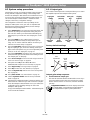
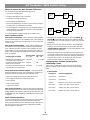
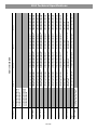
2.1 Introduction
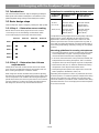
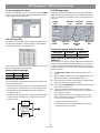
Guidelines for establishing Auto Volume zones
This section describes the basic steps for designing a FreeSpace
4400 system and includes an example. It is assumed that a complete loudspeaker design and layout has already been created.
Loudspeaker Background noise
height is…
is uniform
>25 ft (7.6 m)
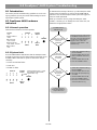
2.2 Basic design steps
There are five basic steps in designing a FreeSpace 4400 system.
2.2.1 Step 1 – Determine source routing
Area 1
●
Area 2
●
Area 3
●
Area 4
●
Area 5
●
Source 2
Source 3
One Auto Volume
zone for every
3600 ft2 (324 m2)
One Auto Volume
zone for every
1800 ft2 (162 m2)
<12 ft (3.7 m)
One Auto Volume
zone for every
1800 ft2 (162 m2)
One Auto Volume
zone for every
900 ft2 (81 m2)
Loudspeaker mounting height and the overall quality of the background noise is used to determine the Auto Volume zoning
requirements. Uniform background noise is found in an area
where no part of the area is louder or quieter than any other. A
room with non-uniform background noise would seem louder in
some areas (people talking, machinery running, etc.) and quieter
in others.
Source 4
●
●
Not recommended
12-25 ft
(3.7-7.6 m)
Decide which sources will be played in each area. Create a
“source map” such as the following one that shows which
sources will be played in each major area of the facility.
Source 1
Background noise
is non-uniform
●
●
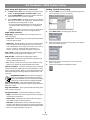
Mounting guidelines for sensing microphones
• The sensing microphone must be mounted at the same height
as the loudspeakers or higher. A sensing microphone must
never be mounted lower than the loudspeaker height.
• In all cases, there must be 6 ft (1.8 m), minimum, between the
loudspeaker and the sensing microphone. This is so that the
microphone does not receive signals only from a loudspeaker.
2.2.2 Step 2 – Determine Auto Volume
requirements
• There must be 35 ft (10.7 m), minimum, between the sensing
microphones of two adjacent Auto Volume zones.
Identify which areas will use Auto Volume. Each Auto Volume
zone must use one AVM (Auto Volume) user interface and one
Bose® sensing microphone to control the volume.
• Avoid placing the microphone near unique noise sources like
HVAC equipment, dishwashers, motors, etc.
When using Auto Volume, remember that you will be adjusting
the volume of an overall area. Imagine that you have a dining area
and a bar adjacent to one another. If the sensing microphone is
placed above the bar, the music may become too loud in the dining area. Likewise, if you place the sensing microphone above
the dining area, the music may never be heard in the bar.
Separating the microphones as much as possible for two zones
is the best practice. Consider the previous example of the dining
area and a bar adjacent to one another. If each of these areas
uses Auto Volume, it is possible to create a situation in the dining
area where the music is too loud simply because the microphone
is too close to the bar.
4 of 66
2.0 Designing with the FreeSpace® 4400 System
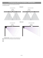
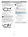
The following are examples of correct and incorrect sensing
microphone placements:
Ceiling Flush
Correct placement
Incorrect placement
Sensing
microphone
Sensing
microphone
Wall Surface
Correct placement
Incorrect placement
Sensing
microphone
Sensing
microphone
Mic
Installer’s Note: In applications where ceiling height is less
than 12 ft (3.6 m), the microphone should be wall mounted.
5 of 66
2.0 Designing with the FreeSpace® 4400 System
When mounting sensing microphones, always maintain a distance of 6 ft (1.8 m) minimum between the microphone and the
loudspeaker.
Wall Surface
Ceiling Flush
Sensing
microphone
≥6 6'
ft
(1.8 m)
≥6 ft
(1.8 m)
Mic
≥6 ft
(1.8 m)
Sensing
microphone
Ceiling Surface
≥6 ft
(1.8 m)
Mic
≥6 ft
6'
(1.8 m)
6'
Sensing
microphone
6 of 66
≥6 ft
(1.8 m)
6'
2.0 Designing with the FreeSpace® 4400 System
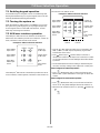
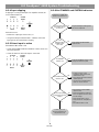
2.2.3 Step 3 – Determine volume
control requirements
2.2.4 Step 4 – Determine the loudspeaker requirements
Decide which areas will have volume controls. Create a control
map, such as the following, showing the types of controls that
will be used, and the areas in which they will be installed.
Determine the loudspeaker coverage required for the design.
Consider the following points as you do this:
AVM (Auto
Volume)
Interface
1
Area 1
AVM (Auto
Volume)
Interface
2
AVM
(Mute)
Interface
1
AVM
(Mute)
Interface
2
• Each type of specifically equalized Bose loudspeaker requires
the dedicated use of one FreeSpace 4400 output channel. If
you are designing a system that uses specific Bose loudspeaker equalization, such as the 102®F loudspeaker, Model
32, Model 32SE, or Model 8, you must dedicate one
FreeSpace 4400 output channel for each loudspeaker type.
●
●
Area 2
Area 3
• Each Auto Volume function requires a separate zone. Each
Auto Volume zone requires the dedicated use of one
FreeSpace 4400 output channel.
Create a loudspeaker map, such as the following, and match the
loudspeaker models to areas (Loudspeaker Qty x Tap = Zone
Power required):
●
Area 4
●
Area 5
●
Model
32SE
AVM (Auto Volume/Mute) user interfaces are available for use
with the FreeSpace® 4400 system. They offers control over
source selection and volume. The interface can be configured as
an AVM (Mute) interface or as an AVM (Auto Volume) interface. If
you have identified an area that uses auto volume, you must configure the interface as an AVM (Auto Volume) interface to control
this zone.
It is also possible to use a 70/100V in-line volume control
between the amplifier output and the loudspeaker. If you plan to
use a 70/100V in-line volume control, be aware that they cannot
be used in zones where either Auto Volume or Dynamic EQ is
used. Auto Volume and Dynamic EQ monitor the amplifier output
and make adjustments accordingly. Using an in-line volume control would cause these functions to operate improperly.
When determining the placement or physical location of the controls, first think about how the control is used. If the control is
very rarely used or it requires a secure location, it should be
placed with the equipment. If the control is for an area that
requires frequent adjustments, then it is best to place the control
in the area being controlled.
7 of 66
Area 1
Area 2
FreeSpace
3-I
Loudspeaker
Qty
Tap
Area
Power
●
2
50
100
5
8
40
1
50
50
●
●
Area 3
Area 4
●
3
4
12
Area 5
●
6
8
48
2.0 Designing with the FreeSpace® 4400 System
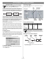
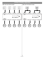
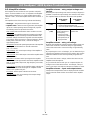
2.2.5 Step 5 – Determine the
FreeSpace® 4400 requirements
Once you have identified the areas that use Auto Volume and
specifically equalized Bose loudspeakers, you can combine different areas based on the types of sources and controls they are
using.
Now we can take a look at how the maps we created can help us
determine the quantity of FreeSpace 4400s we will need.
Sources
1
2
3
Controls
4
●
AV1
AV2
VC1
Loudspeakers
VC2
M32SE
Total W
4400
Ch.
●
100
1
40
2
50
3
Area 1
●
Area 2
●
Area 3
●
Area 4
●
●
●
12
4
Area 5
●
●
●
48
4
●
●
FS3
●
●
●
●
●
●
Total System Power = 250W
By combining the maps you can easily combine sources, loudspeaker types, and control types. The information
placed in this table suggests that Area 1 and Area 3 need to be grouped separately because they are Auto Volume
zones requiring separate FreeSpace 4400 system outputs. Area 2 uses one AVM (Mute) interface requiring one
FreeSpace 4400 output channel. Areas 4 and 5 share a common volume control and can be combined on a third
FreeSpace 4400 output channel. Since only four outputs are required and the total combined power requirement is
less than 400W, only one FreeSpace 4400 unit would be needed for this system.
8 of 66
2.0 Designing with the FreeSpace® 4400 System
2.3 Auto Volume layout examples
Large, open retail space with single music
source
FreeSpace® Acoustimass module
Model 16 (pendant mounted)
Sensing microphone
9 of 66
2.0 Designing with the FreeSpace® 4400 System
Hair salon (Small space with specific noise)
FreeSpace® 3 system
Sensing microphone
10 of 66
2.0 Designing with the FreeSpace® 4400 System
Hotel lobby
22 ft
(6.7 m)
40 ft
(12.2 m)
Model 16
(flush mounted)
Sensing microphone
11 of 66
3.0 FreeSpace® 4400 Hardware Description
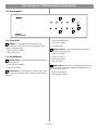
3.1 Front panel
3
2
1
4
3.1.1 Controls
5
Green = Normal operation
Red = Fault condition
1 STANDBY – The STANDBY button switches the unit
Unlit = No signal
between standby and active. The color of the LED above the
switch indicates the status:
4 AUDIO SOURCES – These LEDs indicate the operating
status of the four input sources:
Amber = Unit is in standby
Unlit = Unit is active
Green = Good signal
3.1.2 Indicators
Amber = Low signal
Red = Signal clipping
2 SYSTEM STATUS – The SYSTEM STATUS LED indicates the
Unlit = No signal
condition of the unit:
Green = Normal operation
5 DIRECT INPUT – The color of this LED indicates the condition of the source connected to the DIRECT IN/CONTROL connector on the rear panel.
Red = Fault condition
3 AMP OUTPUTS – These LEDs work in pairs (1 and 2, 3 and
4) and indicate the operating status of the four amplifier output
channels:
12 of 66
Amber = Active bypass
Unlit = Normal operation
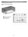
3.0 Freespace® 4400 Hardware Description
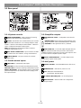
3.2 Rear panel
1
10
2
6
3
4
7
8
9
11
5
13
12
3.2.1 System controls
3.2.3 Amplifier outputs
1 SENSE MICROPHONES – Input connectors for sensing
microphones used with the Auto Volume feature.
6 ZONE OUTPUTS 1/2/3/4 – Loudspeaker connections for
four zones
Installer’s Note: Please notice the polarity markings when
wiring loudspeaker cables to the ZONE OUTPUT connectors.
2 RS-232 – Standard RS-232 communications port. Provides
®
a communications interface for a PC running FreeSpace 4400
Installer™ software. The FreeSpace 4400 Installer™ software is
used to configure the FreeSpace 4400 system.
CAUTION: DO NOT ground the minus (–) terminals.
Note: The RS-232 port should only be used to connect a
FreeSpace 4400 system to a PC.
3 WALL PLATE CONNECTIONS – Input connectors for AVM
1-Zone, AVM 2-Zone User Interface, or Page user interfaces.
4 REMOTE ON/OFF – An input connector for a remote
STANDBY switch.
7 ZONE 4 LINE OUT – A line-level output that duplicates the
program material from LINE 4. May be used to feed another
amplifier installed for a large zone. The 12V control output is used
to connect to Bose® amplifier sequence inputs.
8 MUSIC ON HOLD/PBX OUT – An audio output used to
provide music input to a PBX system
3.2.2 Audio source inputs
3.2.4 AC power
5 LINE 1/LINE 2 – Unbalanced audio inputs
9 OUTPUT VOLTAGE – Sets the ZONE OUTPUT lines to 70/
100V.
AUX MIC/LINE 3 – Balanced audio input with phantom power
PAGE/MIC/LINE 4 – Balanced audio input with phantom power
DIRECT IN/CONTROL – Balanced (DSP bypassed, full amplifier
gain) audio input which can override the sources playing on all
four output channels
10 POWER ON/OFF – Switches AC power on or off
11 Fuse –T6.3(6,3)A L 250V (100/120V) or
T3.15(3,15)A L 250V (220-240V).
12 AC MAINS LINE CORD JACK – AC line voltage input
13 INPUT VOLTAGE – switches need to be configured for
proper input voltage.
13 of 66
4.0 Hardware Installation
4.1 Introduction
4.3 Placement guidelines
This section provides instructions for installing the FreeSpace
4400 system hardware on a tabletop or in a rack.
• Place the FreeSpace 4400 system where it is protected from
heat and allowed adequate ventilation.
4.2 Included accessories
• Place the FreeSpace 4400 system away from direct heat
sources, such as heating vents and radiators.
®
The following accessories are shipped with the FreeSpace 4400
system.
• 2-terminal input connectors (7) – For wiring
Auto Volume mics to the
SENSE MICROPHONES jacks
• Make sure that air can circulate freely behind, beside, and
above the chassis for adequate ventilation. There are intake
vents on the sides and an exhaust vent on the back of the unit.
Do not cover or block the vents.
Installer’s Note: Do not allow the chassis to exceed the
maximum operating temperature of 50° C (122° F). Be aware
of conditions in an enclosed rack that may increase the temperature above room-ambient conditions.
• 3-terminal input connectors (2) – For wiring
equipment to the AUX MIC/LINE 3 jacks
• 4-terminal input connectors (4) – For wiring
equipment to the ZONE 4 LINE OUT,
PAGE/MIC/LINE 4, and
DIRECT IN/CONTROL jacks
• 2-terminal output connectors (5) – For wiring loudspeaker cables to the ZONE OUTPUT jacks
• Rubber feet (4) – For installing the
FreeSpace 4400 system on a level surface
4.4 Shelf mounting the FreeSpace
4400 system
The FreeSpace 4400 system is ideal for shelf mounting. The
included accessory kit contains four rubber feet for the bottom of
the FreeSpace 4400 chassis. The rubber feet will protect the surface on which the FreeSpace 4400 system is installed and help
prevent movement of the FreeSpace 4400 system. Be sure to follow the “Placement Guidelines” previously described when
choosing a location for the FreeSpace 4400 system.
• Rack ears (2) ) – for rack
mounting the the unit.
Includes (8) M4 x 12mm
screws.
• Replacement voltage label (2) – Used on
the OUTPUT VOLTAGE selection switch
• FreeSpace 4400 Installer™ software
CD – Contains application software for
programming the FreeSpace 4400
system
14 of 66
4.0 Hardware Installation
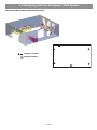
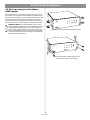
4.5 Rack mounting the FreeSpace
4400 system
The FreeSpace 4400 system requires three 1.75" (44 mm) rack
space units with a 16" (406 mm) inside depth (including the rear
supports). When mounting, use four screws with washers to prevent marring the front panel. Neoprene rubber washers are a
good choice because they grip the screw head and prevent the
screws from backing out from vibration or during transportation.
Installer’s Note: If the FreeSpace 4400 system is to be
transported while mounted in a rack, be advised that the rear
of the FreeSpace 4400 system must be mechanically supported. Install a shelf under the unit or use brackets in such a
way as to support the rear of the unit. Failure to use proper
mounting hardware may result in damage to the FreeSpace
4400 system during transport.
Attaching rack ears to the FreeSpace 4400 chassis
ic
Attaching the FreeSpace 4400 chassis to the
rack (mounting screws not provided)
15 of 66
4.0 Hardware Installation
4.6 Installing accessories
4.6.2 Auto volume microphone inputs
Connect each sensing microphone to the SENSE MICROPHONES jacks on the FreeSpace 4400 rear panel.
Installer’s Note: Disconnect the FreeSpace 4400 system
from the AC (mains) power before making any input/output
connections.
4.6.1 Sensing microphones
Required accessory:
FreeSpace® 4400 System Auto Volume Mic Kit [PC042354 (U.S.),
PC042355 (Euro)]
Paint plug
Wall plate-microphone
assembly
(2) Wire nuts
4.6.3 User interfaces
(2) #6-32 (3 mm) screws
Required accessory: FreeSpace® 4400 System AVM 1-Zone
User Interface [PC042351] or
FreeSpace® 4400 System AVM 2-Zone
User Interface [PC042352] or
FreeSpace® 4400 System Page User
Interface [PC042353]
Microphone installation:
The wall plate-microphone assembly can be installed using a
single-gang junction box, or the microphone can be removed
from the wall plate and mounted directly on a flat surface.
Junction box installation
Surface-mounted mic
A
Wall plate
B
Keypad
/
L
TE
MU VO
TO
AU
Recommended wire length:
Up to 2000 ft (610 m) max., 24 AWG (0.2 mm2) shielded twisted
pair (shield tied to minus at FreeSpace 4400, floated at sense
mic).
Required additional equipment (not supplied):
Painting:
Before painting the wall
plate, install the supplied temporary plug
over the microphone
opening. Remove the
plug when finished.
C
RJ45
connector*
E
Double-gang
junction box
D
Cat 5 cable*
(with 4 twisted pairs)
Mounting locations:
For mounting instructions, see “Mounting guidelines for sensing
microphones” on page 4.
*FreeSpace® 4400 System AVM 2-Zone User Interface requires
the use of two (2) RJ45 connectors and two (2) Cat 5 cables.
16 of 66
4.0 Hardware Installation
Assembly:
User interface schematic Page user interface:
E
12345678
+5VD
+5VD
.33µF
C7
D1
LED
A
D6
LED
D
B
R6
562
+5VD
R1
562
MU
AU TE /
TO
VO
L
S6
S1
Zone 1
+5VD
+5VD
User interface schematic AVM (Auto Volume/Mute)user interface*:
Zone 2
D5
LED
D2
LED
12345678
R5
562
+5VD
R2
562
+5VD
.33µF
C7
D6
LED
D1
LED
S5
S2
R6
562
+5VD
R1
562
+5VD
+5VD
S6
S1
Volume Up
Source 1
LED
D3
LED
R3
562
D2
LED
D5
LED
S4
All Zones
Page
R5
562
R2
562
S5
S2
S3
D4
R4
562
+5VD
+5VD
Zone 4
Zone 3
Volume Down
Source 2
Recommended cable lengths:
+5VD
+5VD
LED
D3
LED
R3
562
S3
Source 3
4400
D4
R4
562
S4
2000 ft (610 m) max.
One wall plate
using CAT 5
1300 ft (396 m) max.
Two wall plates
using CAT 5
Mute
or
Auto Volume
On/off
4400
Installer’s Note: Only two (2) user interfaces can be connected in series.
*FreeSpace® 4400 System AVM 2-Zone User Interface has two
separate 8-terminal connectors. Each connector uses the same
wiring schematic represented above.
17 of 66
4.0 Hardware Installation
4.6.4 User interface connections
User interface wiring:
Installer’s Note: Use only standard ethernet (Cat 5) cable to
connect the user interface to the FreeSpace 4400 system.
DO NOT use crossover (XOV) cables.
Connect the user interface from each zone to the appropriate
WALL PLATE CONNECTION jack.
Installer’s Note: Only use standard ethernet (Cat 5) cable
to connect the user interface to the FreeSpace 4400 system.
DO NOT use crossover (XOV) cables.
WALL PLATE
CONNECTOR BLOCK
4400 RJ45
PIN 1-8
POS 1
PIN 1
POS 2
PIN 2
POS 3
PIN 3
POS 4
PIN 4
POS 5
PIN 5
POS 6
PIN 6
POS 7
PIN 7
POS 8
PIN 8
PIN 8
PIN 1
For operating information, see “User Interface Operation” on
page 49.
18 of 66
4.0 Hardware Installation
4.7 System wiring
4.7.2 Remote standby switch
If you are installing a remote standby switch, connect it to the
REMOTE ON/OFF input.
Installer’s Note: Disconnect the FreeSpace 4400 system
from the AC (mains) power before making any input/output
connections.
Remote Standby
Switch
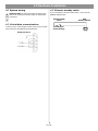
4.7.1 Serial data communications
Connect your PC to the FreeSpace 4400 system using a straightwired serial data cable (DB9 male to DB9 female).
RS232 port pinout
19 of 66
Normally Open
Switch (latching)
4400
REMOTE ON/OFF
4.0 Hardware Installation
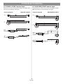
4.7.3 LINE 1/LINE 2 source input
4.7.4 AUX MIC/LINE 3 source input
Audio sources can be connected to the LINE 1 and LINE 2 inputs
using one of the following cable types.
A microphone or an audio source can be connected to the MIC/
LINE 3 input using one of the following cable types.
4400 LINE 1/LINE 2
Source Connector
S
RCA
4400 AUX MIC/LINE 3
Source Connector
S
S
T
T
RCA
S
S
T
T
T
1
S
3
1
XLR
T
2
2
1
3
3
1
XLR
R
2
2
3
S
T
Phone
Plug
(Balanced)
T
R
S
T
S
S
R
T
S
Phone
Plug
(Balanced)
S
R
S
T
T
T
Phone
Plug
(Unbalanced)
S
T
S
T
Phone
Plug
(Unbalanced)
20 of 66
S
T
4.0 Hardware Installation
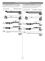
4.7.5 PAGE/MIC/LINE 4 source input
4.7.6 DIRECT IN/CONTROL source input
A microphone or an audio source can be connected to the PAGE/
MIC/LINE 4 input using one of the following cable types.
A microphone or an audio source can be connected to the
DIRECT IN input using one of the following cable types. The control (PTT) input requires a normally open switch.
4400 PAGE/MIC/LINE 4
Source Connector
4400 DIRECT IN/CONTROL
Source Connector
RCA
S
S
T
RCA
T
S
S
T
T
PTT
PTT
1
1
3
1
XLR
2
3
2
3
1
XLR
2
2
3
PTT
PTT
S
S
R
T
Phone
Plug
(Balanced)
R
S
T
R
T
PTT
Phone
Plug
(Balanced)
R
S
T
PTT
S
T
Phone
Plug
(Unbalanced)
S
S
T
T
Phone
Plug
(Unbalanced)
S
T
PTT
PTT
Normally
Open Switch
(latching)
Normally
Open Switch
(latching)
PTT
PTT
21 of 66
4.0 Hardware Installation
4.7.7 Amplifier ZONE OUTPUT outputs
4.7.8 Output voltage setting (70/100V)
Loudspeaker systems in up to four zones can be connected to
the ZONE OUTPUT amplifier outputs.
Check the OUTPUT VOLTAGE switch setting and change if
needed.
Installer’s Note: Please notice the polarity markings on
the ZONE OUTPUT 1-4 connectors. Wire each connection as shown, using the 2-terminal output connector from
the accessory kit.
OUTPUTS
Installer’s Note: DO NOT
ground the minus (–) side of
the line.
1.
ZONE 1
ZONE 2
ZONE 3
ZONE 4
To change the setting to 70V or 100V, remove the label,
change the switch setting and replace the label. Additional
labels are supplied in the accessory kit.
Install a two-terminal
output connector
(supplied) on the
loudspeaker cable
from each zone.
+
–
2.
Installer’s Note: Disconnect power from the FreeSpace
4400 system before changing the OUTPUT VOLTAGE setting.
Plug the loudspeaker cable connectors into the appropriate
ZONE OUTPUT jack.
Installer’s Note: Be sure to position the cable connector in
the correct orientation for the ZONE OUTPUT jacks: Screw
heads face upward for ZONE OUTPUT 1 and 2 jacks, screw
heads face downward for ZONE OUTPUT 3 and 4 jacks.
®
LIS
TE
D
AU 91
EQ DI 7D
UI O
Th PMENT
subis de
ha jec
rm
rece
fu
Co ive
mp
22 of 66
4.0 Hardware Installation
4.7.9 ZONE 4 LINE OUT output
4.8 AC power connections
The ZONE 4 LINE OUT jack provides a line-level output that
duplicates the program material on LINE 4. This may be used to
feed another Bose® amplifier installed for a large zone. The 12V
control output is used to connect to Bose amplifier sequence
inputs.
The rear connection panel of the chassis provides an input voltage switch for 100V, 120V, 220V, 230V, or 240V use. Check the
switch settings to be sure it is appropriate for the local power
standard.
INPUT VOLTAGE
4400 ZONE 4 LINE OUT
Source Connector
100V
S
RCA
S
T
T
XLR
2
220V
230V
240V
120V
230V
240V
100V
120V
100V
220V
220V
230V
240V
120V
230V
240V
120V
3
1
100V
220V
INPUT VOLTAGE
12V
1
100V
120V
2
3
INPUT VOLTAGE
12V
S
Phone
Plug
(Balanced)
R
S
T
S
T
S
220V
230V
240V
120V
230V
240V
INPUT VOLTAGE
12V
Phone
Plug
(Unbalanced)
100V
220V
220V
R
T
100V
120V
230V
T
12V
100V
120V
100V
220V
220V
230V
240V
120V
230V
240V
INPUT VOLTAGE
Control Signal
100V
120V
100V
220V
220V
230V
240V
120V
230V
240V
240V
12V
Bose Amplifier
WARNING: Be sure to disconnect the unit from AC power before
changing the input voltage settings on the rear connection panel.
4.8.1 Fuse type
Be sure the proper supplied fuse is inserted in the fuse holder.
Replace the fuse as needed with the proper type. 100V and 120V
units require a T6.3(6,3)A L 250V fuse. 220V, 230V, and 240V units
require a T3.15(3,15)A L 250V fuse.
4.8.2 AC POWER connection
Insert the proper power cord for the voltage used in your region.
23 of 66
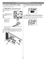
5.0 Using FreeSpace® 4400 Installer™ Software
5.1 Installing the software
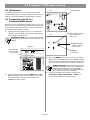
2.
Insert the FreeSpace® 4400 Installer™ software CD into the CD
tray of your laptop PC.
If the install program does not start automatically, open “My computer” from the desktop, double-click on the CD-ROM drive icon,
and double-click on the “Setup.exe” icon.
Set the FreeSpace 4400 rear panel POWER switch to
ON.
Verify that the STANDBY indicator is lit on the FreeSpace 4400
front panel. Then press the STANDBY push button to switch the
FreeSpace 4400 hardware to the operating mode.
POWER switch
Follow the instructions on the screen to complete the installation.
Programmer’s Note: For the FreeSpace 4400 Installer™
software to operate properly, your PC must be connected to
the FreeSpace 4400 system. See the following section,
“Connecting to the FreeSpace 4400 system”.
5.2 Connecting to the FreeSpace 4400
system
To create a design file in FreeSpace 4400 Installer™ software,
your PC must have an active connection with the FreeSpace
4400 system hardware. This means that your PC must first be
physically connected to the hardware device with a serial cable
and then that connection must be activated using the software.
STANDBY indicator
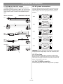
1. Connect your PC to the FreeSpace 4400 system.
Using a serial cable (not supplied), connect the RS-232 serial port
of your laptop PC to the RS-232 serial port on the rear panel of
the FreeSpace 4400 system.
Programmer’s Note: If your computer does not have
an RS-232 port you will need to use an RS-232 to USB
adapter.
RS-232 serial data cable
(not provided)
Laptop PC
RS232
4400 system
Programmer’s Note: The RS-232 port should only be
used to connect a FreeSpace 4400 system to a PC.
24 of 66
STANDBY push button
5.0 Using FreeSpace® 4400 Installer™ Software
3.
Launch the FreeSpace 4400 Installer™ software.
Programmer’s Note: If you encounter the “Choose
COM port” dialog box, immediately follow the displayed
recommendations for correcting the problem. DO NOT
click the Cancel button until after trying each of the
given recommendations.
The FreeSpace 4400 Installer software splash screen will appear
on your screen.
Programmer’s Note: Before dismissing the “Choose
COM port” dialog, select the COM 2 port and click Try
Again. Not doing this will cause the COM 1 port to be
locked.
After the splash screen, a status dialog will appear and report the
status of each installation stage.
After your PC successfully connects to the FreeSpace 4400 hardware, the Choose COM port dialog should automatically close. If
not, close the window manually.
5.
If you have connected to a new FreeSpace 4400 system, use the FreeSpace 4400 front panel window to
set up the hardware.
Refer to the “FreeSpace® 4400 System Setup” on page 34.
Programmer’s Note: Clicking the Close button on the
hardware connection status dialog will cause a communications failure, locking the serial port. If the port locks,
you must restart your computer.
At this point in the installation, the software looks for a
connected FreeSpace 4400 system, and if found, then
checks to see what version firmware is running in the
FreeSpace 4400 system.
If you get a “No hardware detected” dialog, see “No
hardware detected” on page 26.
If you get an Incompatible Microcontroller code dialog,
see “Incompatible microcontroller code” on page 26.
4.
If prompted, select the correct COM port for the
FreeSpace 4400 system.
By default, the FreeSpace 4400 Installer software tries to locate a
hardware device on the COM 1 serial port. If the FreeSpace 4400
system is not detected on COM 1, the software displays a
“Choose COM port” dialog box asking you to select the correct
serial port.
25 of 66
5.0 Using FreeSpace® 4400 Installer™ Software
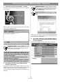
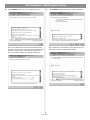
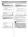
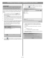
5.2.1 No hardware detected
If after launching the FreeSpace 4400 Installer™ software a hardware device is not found, the status window reports a failure to
detect connected hardware:
In this case, clicking the Close button results in a blank hardware
setup window.
• Click Upgrade to upload the latest version of microcontroller
code to the device. When the "Upload Complete" window
appears, click Close. Then, finish the installation and configure
your hardware device.
Programmer’s Note: Upgrading new software does
not change any of your current configuration settings.
When the upgrade is finished, your current configuration
will be restored.
• Click Cancel to exit the software and leave the device
untouched.
Programmer’s Note: The FreeSpace 4400 Business
Music System is only compatible with the FreeSpace 4400
Installer software. The FreeSpace 4400 system is incompatible with the FreeSpace E4 system's FreeSpace Installer
software. Additionally, the FreeSpace E4 system is incompatible with the FreeSpace 4400 Installer software.
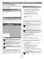
5.2.3 Sample design files
Two sample design files are included with your FreeSpace® 4400
Installer™ software:
• sample70V.fsi – for 70V FreeSpace 4400 systems
Programmer’s Note: If you are not connected to the
FreeSpace 4400 system, you can see an example of the
FreeSpace 4400 front panel by opening the sample
design file provided on the FreeSpace 4400 Installer CD.
See “Sample design files” on page 26.
Programmer’s Note: To configure a FreeSpace 4400
system, the FreeSpace 4400 system must be powered
up. DO NOT switch the FreeSpace 4400 system to
STANDBY mode while the FreeSpace 4400 Installer
software is running.
Programmer’s Note: The FreeSpace 4400 Installer
software does not notify you if there is a loss of communication between the FreeSpace 4400 system and your
PC.
• sample100V.fsi – for 100V FreeSpace 4400 systems
They can be used to display a FreeSpace 4400 front panel when
your PC is not connected to a system hardware device.
To open the sample design file:
1.
Click the Open file tool in the FreeSpace 4400 Installer
software window.
2.
Select the name of the sample design file in your
FreeSpace 4400 Installer software directory:
C:\Program Files\FreeSpace 4400 Installer 1.0.0.
3.
Click the Open button in the dialog box.
4.
Click on the “Bose FreeSpace 4400” system name in the
System Overview pane. The FreeSpace 4400 front panel will
appear in the application window.
5.2.2 Incompatible microcontroller code
If the FreeSpace® 4400 Installer™ software finds that your system
is running an older version of firmware (microcontroller code), the
following window appears, giving you the opportunity to upgrade
the code.
26 of 66
Programmer’s Note: If you are not connected to the
FreeSpace 4400 system when you open a design file, all
controls within the software are grayed out and not
accessible.
5.0 Using FreeSpace® 4400 Installer™ Software
5.3 The FreeSpace 4400
Installer™ software user
interface
The following describes the software user interface.
Tool box
Mode buttons
Window sizing tools
Work
area
Control
pane
System overview pane
27 of 66
5.0 Using FreeSpace® 4400 Installer™ Software
Tool box
Open File – Displays the file open dialog.
System overview pane – After connecting your PC to a system,
this pane will list the hardware device. After you select the device
to establish a connection, the name of the hardware device is
highlighted.
Save File – Saves the design file and the current settings of the connected hardware device to your PC’s
hard drive.
Name of system to which
your PC is connected
Currently-connected device
Flash Hardware Configuration – Sends the design
file and current settings from your PC to the memory of
the connected hardware device. This determines the
default startup state of the device.
Detect Hardware – Uploads the design file and configuration settings from the system hardware to your
PC.
Help – Launches the online help system.
Mode buttons
Work area – The functions available for each mode are displayed
in the work area.
Set Up System – Selects the
Set Up System mode enabling
you to set up the system hardware or create a schedule to
automate system operation.
Hardware – Selects the Set Up
Hardware mode.
Schedule – Selects the Set Up
Schedule mode.
Control pane – The control pane is used to display the controls
for the function selected in the work area.
Service Hardware – Selects
the Service Hardware mode.
Window sizing tools
Minimize Window – Collapses the application window
into the Windows Task bar.
Maximize Window – Function not available.
Close Application – Closes the application program.
28 of 66
5.0 Using FreeSpace® 4400 Installer™ Software
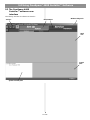
5.4 Set Up Hardware mode
Using the Set Up Hardware mode, you can create new system
configurations. The following example displays the software front
panel for the FreeSpace® 4400 system.
The hardware setup window consists of three panes:
System overview pane – This pane displays the selected hardware device that you are currently configuring. For more information on the system overview pane, see “The FreeSpace 4400
Installer™ software user interface” on page 27.
Hardware pane – The hardware pane displays a software front
panel of the hardware device that you selected in the system
overview pane. Reading from left to right, this diagram shows you
the functions and signal paths from input sources to output
zones. All functions internal to the connected hardware device
appear on a gray background.
Functions are selected by clicking on a button. When you select a
function, all controls for that function appear in the control pane.
Control pane – When you select a function in the hardware pane,
the controls that affect operation, configuration, or setup of the
selected function or device appear in the control pane. On some
control panes, you can view additional functions by clicking on
More.
Selected function
Hardware
pane
Connected
hardware
System overview pane
29 of 66
Control pane for
selected function
5.0 Using FreeSpace® 4400 Installer™ Software
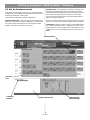
5.5 Set Up Schedule mode
The Set Up Schedule mode allows you to automate a system by
creating up to 64 events. To select the Set Up Schedule mode,
click the Schedule button under Set Up System. The features
and controls of the Set Up Schedule window are as follows:
Event list selection tabs – These tabs determine which list of
events is displayed. Click the top tab to display the system event
list. Click any one of the ZONE tabs to display the event list for a
selected zone.
Event list – This list contains all scheduled events for the
selected system or zone. Each event entry includes the time of
the event, a description of the event, and the days of the week on
which the event will occur.
Control pane – When you select an event in the event list, this
pane displays the settings for that event. Any changes made to
these settings are reflected in the event listing.
Remove Event button – This button will remove a selected event
from the event list.
Hardware clock display – The clock display shows the current
date and time of the hardware clock. The Set Clock button is
used to set or change the clock.
System overview pane – This pane displays the selected hardware device that you are automating. For more information on the
system overview pane, see “The FreeSpace 4400 Installer™ software user interface” on page 27.
Add event buttons – The Add Event buttons include On/Off,
Mute, Volume, Source, and Auto Volume. The On/Off button is
a system event only. Mute, Volume, Source, and Auto Volume
are zone events. When you click one of these buttons, the event
is added to the list and the controls for the selected event are displayed in the Event control panel. As events occur, the number of
remaining events are displayed in parentheses above the On/Off
button.
Event list
Event list
selection
tabs
Add event buttons
Hardware
clock
display
System overview pane
Control pane
Event counter
30 of 66
Remove
event
button
5.0 Using FreeSpace® 4400 Installer™ Software
5.5.1 Setting the clock
The date and time of the hardware clock is initially set in Eastern
Standard Time. After your PC is connected to the hardware,
check the clock and set it as necessary for the time zone and
region of your installation.
Adds a system Auto On/Off event
This event applies only to the whole system. You can select individual on or off times for the day(s) you choose. Or, you can
select on and off times in a single statement.
Programmer’s Note: One Auto On/Off event specifies
both an “On” time and an “Off” time and is counted as two
events.
To adjust the clock settings manually, click the Set Clock button
in the clock panel. The Clock Settings window opens, allowing
you to make adjustments to the date and time. Click Apply or OK
to set the clock in the hardware, or click Cancel to close the window and leave the clock settings unchanged.
Adds a zone Mute event
This event allows you to mute/unmute the zone output at a
specified time on selected days of the week.
5.5.2 Adding events
When you click the On/Off, Volume, Source, or Auto Volume
event button, an event of that type is added to the event list. At
this point you can change the event settings. When the event list
exceeds the length of the pane, the software will add a scroll bar
on the right side.
A maximum of 64 events may be added to a system. This means
that the total number of events from all event lists must not
exceed 64. An On-Off event consumes two events, while source
change, volume change, and Auto Volume events consume one
apiece. A counter is provided in the Schedule mode window to
keep track of the number of remaining events.
Adds a zone Volume Change event
This event allows you to change the volume level at a specified
time on selected days of the week.
Remaining events
counter
Programmer’s Note: The maximum/minimum volume
stops cannot be adjusted in this pane. To adjust these limit
stops, select the Output Gain function in the Set Up Hardware mode.
Zone events programmed to occur at the same time as a “System ON” event will not occur. To ensure that zone events will happen, they must be programmed to occur 15 minutes after the
“System ON” event. For example, if a “System ON” event is programmed to occur at 8:00 AM, the first zone event should be programmed to occur at 8:15 AM.
Installer’s Note: Flashing the FreeSpace 4400 Installer software configuration file to the FreeSpace 4400 system sets the
default state of the system when it is turned on. Whenever
possible the default state of the system should be set to meet
the requirements most likely to occur after a scheduled “System ON” event.
31 of 66
5.0 Using FreeSpace® 4400 Installer™ Software
5.5.3 Viewing and changing event
settings
Adds a zone Source Change event
This event allows you to change the source at a specified time on
selected days of the week.
To view any event and change the settings, first click the system
or one of the zone tabs. Then select an event in the list to display
the event settings in the control pane. Now, you can edit the settings just as when an event is added.
5.5.4 Removing events from the list
To remove an event from the list, select the event by clicking on it
and then click the
(Remove Event) button.
Programmer’s Note: After changing any event settings
or removing an event from the list, you must flash the
hardware in order for the change to take effect.
Adds a zone Auto Volume event
This event allows you to turn Auto Volume on or off at a specified
time on selected days of the week.
Programmer’s Note: Do not schedule an Auto Volume
event on a zone that is not set up for Auto Volume.
Programmer’s Note: Events are only saved to the
FreeSpace 4400 system when you click the
Hardware Configuration) button.
(Flash
32 of 66
5.0 Using FreeSpace® 4400 Installer™ Software
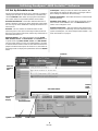
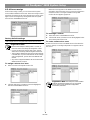
5.6 Service Hardware mode
Service Hardware button
The Service Hardware mode provides a list of any system errors
that have occurred.
To view the Error Log, click the Service Hardware button. If you
are already connected to hardware, the Error Log is retrieved
from the hardware and displayed in the window. If not yet connected, select the hardware in the System Overview pane and
after establishing the connection, click
and then click
(Detect Hardware)
.
When the FreeSpace 4400 system is powered on, it performs a
self-test. Any errors detected during a power-on cycle are
appended to the Error Log. Likewise, any errors detected during
normal operation are appended to the Error Log. The Error Log
provides diagnostic information for repair technicians to help
them repair the system.
For more information on reported errors, see “FreeSpace® 4400
system Error Log” on page 55.
The buttons below the Error Log display allow you to manage the
Error Log information:
Uploads the current Error Log listing
from the hardware. If you recently
cleared the log, the Error Log will contain information reported only since the
time you cleared it.
Error Log
Hardware version
numbers
Exports the Error Log to your hard
drive as a text file.
Clears the Error Log from the window
and the FreeSpace 4400 system.
Type of alarm
Name of test
Test results
33 of 66
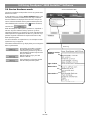
6.0 FreeSpace® 4400 System Setup
6.1 Introduction
Rear
POWER switch
Front
SYSTEM STATUS indicator
Green = Operating
Red = Fault
This section provides instructions on setting up an installed
FreeSpace 4400 system. To set up a FreeSpace 4400 system you
need a PC running the FreeSpace® 4400 Installer™ software.
6.2 Connecting your PC to a
FreeSpace 4400 system
Before you can set up the FreeSpace 4400 system, your PC must
first be physically connected to the FreeSpace 4400 system with
a serial cable and then that connection must be activated using
the FreeSpace 4400 Installer™ software.
1.
Connect the RS-232 serial port of your PC to the RS-232
serial port on the rear panel of the FreeSpace 4400 system
using a straight serial data cable.
Programmer’s Note: If your computer does not have
an RS-232 port you will need to use an RS-232 to USB
adapter.
STANDBY indicator
Amber = Standby
Unlit = Active
Laptop PC
RS-232 straight
serial data cable
(not provided)
RS232
STANDBY
push button
4400 system
3.
Press the STANDBY push button to switch the FreeSpace
4400 system to the operating mode. The STANDBY indicator
will turn off and the SYSTEM STATUS indicator will be green.
(If a system fault condition exists, the indicator will be red.)
Programmer’s Note: If the FreeSpace 4400 system
experiences a brownout or power loss, the FreeSpace
4400 system will return to power in the STANDBY
mode. To return to operation, press the STANDBY button, or press any key on any user Interface.
2.
Set the FreeSpace 4400 rear panel POWER switch to ON.
When the FreeSpace 4400 system is powered up and ready,
the SYSTEM STATUS indicator is dark (unlit) and the
STANDBY indicator is amber.
4.
34 of 66
Launch the FreeSpace 4400 Installer™ software. See
“Launch the FreeSpace 4400 Installer™ software.” on
page 25 for the software launching sequence.
6.0 FreeSpace® 4400 System Setup
6.3 System setup procedure
6.3.1 Output gain
The first time you turn on a FreeSpace 4400 system it loads its
factory (default) configuration settings. These settings were
stored in the FreeSpace 4400 when it was manufactured. Once
your PC is fully connected to the FreeSpace 4400 system, you
can use the FreeSpace 4400 Installer™ software to make
changes to the factory configuration settings.
The controls in the Output Gain control panel allow you to control
the amplifier output of the FreeSpace 4400 system.
Page gain
setting
Max. gain
stop
Gain Slider
(Volume)
Clipping
indicator
The configuration contains the “start-up” settings for the
FreeSpace 4400 system. Once your work is completed and
flashed to the FreeSpace 4400 hardware, the new settings
become the startup configuration.
1.
Select Output Gain for each zone and mute the output. This
prevents any damage to loudspeakers during this procedure. This also allows you to work without disturbing any
other people in your work area. See “Output gain” on this
page.
2.
Set up the ZONE for each output channel. Choose a
Speaker EQ (default is No EQ) for the speakers you are
using. You can use the Subzones table to document your
subzones. See “Zone setup” on page 36.
3.
Page gain
button
Set up the Input Gain controls for each source. Choose settings for input type, gain, and source leveling. If the input
type is set for microphone use, you can turn phantom power
(+12V) on or off. See “Input gain” on page 37.
4.
Set up the Output Gain controls for each zone. Set the minimum/maximum gain (volume) limits and the initial gain level.
See “Output gain” on this page.
5.
Select Source Assign for each zone and assign sources for
each. See “Source assign” on page 39.
6.
Set up the source EQ for AUX MIC/LINE 3 and
PAGE/MIC/LINE 4 inputs. See “Source EQ” on page 40.
7.
Select Page Set Up. See “Page setup” on page 40.
8.
Select EQ for each zone. See “Zone EQ” on page 42.
9.
Select the Dynamic EQ state for each zone. See “Dynamic
EQ” on page 43.
Mute
selection
Min. gain
stop
Signal level
meter
Factory default settings
Gain
Max. Gain
Min. Gain
–20 dB
0 dB
–60 dB
Page Gain
–20 dB
Mute
Off
Output gain circuit block diagram
Gain
adjustment
Signal
level
meter
10. Set up Auto Volume. See “Auto Volume” on page 43.
Output gain setup sequence
11. Create a System Schedule. See the “Set Up Schedule
mode” on page 30.
1.
12. Click the flash configuration button in the upper toolbox. You
will be asked to confirm that you want to save the configuration to the FreeSpace 4400 hardware. Once you confirm, the
configuration and scheduling settings are sent to the
FreeSpace 4400 system.
A copy of the FreeSpace 4400 Installer™ software design file
is also sent to the hardware.
35 of 66
Clipping
detector
Set the maximum output gain.
This sets the maximum allowed volume within a zone. Play a
source that will be used in that zone and raise the volume
slider to the zero level. If it is too loud, lower the maximum
gain stop.
Programmer’s Note: If the source still plays too loud at
the –30 dB setting, you should lower the tap setting on
your loudspeakers for optimal system performance.
6.0 FreeSpace® 4400 System Setup
2.
Set the minimum output gain.
This sets the desired minimum volume within a zone. Play a
source that will be used in the zone and adjust the volume
slider to the desired minimum level. Raise the minimum gain
stop up to the volume slider level.
3.
Set the initial output gain.
When the FreeSpace 4400 system is switched from standby
to operating mode, it loads its configuration (initial settings).
Wherever the volume slider is set when you save the configuration becomes the initial gain setting.
Page Gain Setup
Programmer’s Note: In an Auto Volume zone, the
maximum and minimum level stops are disabled once an
Auto Volume calibration is run.
Mute selection – When checked, the Mute selection quiets the
output audio.
Signal level meter – The signal level meter displays the output
level of the FreeSpace 4400 system.
Clipping indicator – The clipping indicator tells you when clipping is occurring in the amplifier. When indicated, clipping is
caused by a low/reduced AC line voltage.
6.3.2 Zone setup
The Page Gain function allows you to independently define a
page level for each of the four output zones of the FreeSpace®
4400 system.
The Zone Setup control panel allows you to select the EQ for the
loudspeakers used in a zone and to document (optional) the
number of loudspeakers in a subzone and their tap settings.
1.
Select the Out Gain function for the zone with paging.
2.
Using the output gain slider, set the gain to the paging level
you want for the output zone.
3.
Click the Set button. The new Page Gain level is displayed
above the Set button.
Loudspeaker
model drop list
Add
subzone
Delete
subzone
Programmer’s Note: When working with the Page Gain
function, please note the following behaviors:
• Moving the maximum gain stop to a point below the
current Page Gain setting will set the Page Gain to the
level of the new maximum output gain.
• Moving the minimum gain stop to a point above the current Page Gain setting will set the Page Gain to the level
of the new minimum output gain.
Subzone table
• If Auto Volume was calibrated for a zone with paging,
you will be able to adjust the Output Gain and set the
Page Gain when Auto Volume is off.
Output gain controls
Page Gain – Displays the Page Gain setting for the output zone.
Speaker EQ – The Speaker EQ drop-down list contains a list of
loudspeakers by model name. The selected loudspeaker equalization settings are sent to the FreeSpace 4400 system.
Page Gain Set Button – Sets the Page Gain to the level defined
by the gain slider position.
Gain slider – This slide control adjusts the output gain. As you
click and drag the slider, you will hear the level change. Release
the mouse when you hear the level you want. The output gain is
adjusted in an installed system by the Volume up/down buttons
on the AVM (Mute) or AVM (Auto Volume) user interface.
Programmer’s Note: In zones using Auto Volume, the
volume may only be adjusted using the Auto Volume
interface.
Maximum and minimum gain stops – The maximum and minimum gain stops determine the maximum and minimum volume
levels. Click and drag each stop to the values you want. If the
stop meets the volume slider, the volume slider will move with the
stop until the new setting is reached.
When a AVM user interface is used in a zone, the volume control
cannot set the gain outside these limits.
Mount code
Each item in the list indicates a type of mounting: (F) for flush, (S)
for surface, and (P) for pendant. Some items are listed more than
once because they may be mounted in more than one way. For
example, the Model 16 has two entries: one with an (F) for flush,
and one with a (P) for pendant.
The list also includes commonly used groupings, such as combinations of FreeSpace® 3 bass and mid/high devices. Use these
settings when you are using the FreeSpace 3 bass on the same
loudspeaker line with other loudspeakers.
36 of 66
6.0 FreeSpace® 4400 System Setup
6.3.3 Input gain
Programmer’s Note: If you are using the FreeSpace
4400 system to drive loudspeakers that are not Bose®
products, choose the No EQ setting or one of the four
high-pass filter settings at the end of the list.
The Input Gain controls allow you to adjust functions related to
the input source signal.
The No EQ setting helps protect the FreeSpace 4400 against loudspeaker transformer saturation when non-Bose loudspeakers are
connected to the FreeSpace 4400 hardware. This setting acts as a
band pass filter and allows energy between 80 Hz and 16 kHz to be
sent to the amplifier section of the FreeSpace 4400 electronics.
Gain
slider
Source type
Input signal
level meter
®
If you change the loudspeaker EQ type, any subzones will be automatically changed to the new Speaker EQ setting, and be given the
default loudspeaker tap. Depending on the quantity and tap of loudspeakers, you could receive an error message notifying you that the
system exceeds the 400 W limitation of the FreeSpace 4400 system. If this problem occurs, delete the subzones from the subzone
list. This will allow you to change the loudspeaker EQ type.
Subzones table – The Subzones table allows you to document
the loudspeakers used in a zone.
A zone is a group of loudspeakers that are driven by the same
amplifier output channel. A subzone is a group of loudspeakers
within a zone that use a common tap or are of a common type.
For example, you may have installed ten Model 16 loudspeakers
in a dining room and set it up as a zone to be driven by channel 1.
In this zone you may have established two subzones, one with
five Model 16 loudspeakers tapped at 8W and the other with five
tapped at 16W.
Mic phantom
power On/Off
Opti-source
input leveling
On/Off
Factory default settings
Input Type
Initial Gain
Gain Range
Opti-source
Mic
40 dB
80 dB
Off
Line
0 dB
70 dB
Off
Mic Page
40 dB
80 dB
On
Line Page
0 dB
60 dB
On
Programmer’s Note: Input gain controls are disabled if
the input channel is routed to a zone in which Auto Volume is enabled (on). You will only be able to change/
adjust the input gain by resetting the Auto Volume for the
affected zone.
To add a subzone
Click the Add button. When the Add Subzone window appears,
enter a name for the new subzone, select the loudspeaker model
installed, enter the quantity, and select a tap setting. The Model
Name list will include only loudspeakers that are compatible with
the Speaker EQ you selected.
Signal
present
indicator
Input gain circuit block diagram
Click OK to add the selections to the subzone table.
Gain
adjustment
Signal
level
meter
3-band
equalizer*
EQ
Opti-source
leveling
SRC
LEVEL
Signal detector
* Only available for AUX MIC/LINE 3 and PAGE/MIC/LINE 4 inputs. See
“Source EQ” on page 40.
To delete a subzone
In the subzones table, select the subzone to be removed and
click the Delete button.
37 of 66
6.0 FreeSpace® 4400 System Setup
Input gain setup sequence
Input gain meter – The input gain meter indicates the average
input signal level of the hardware. The meter is divided into three
color segments:
1.
Set Opti-source® Control to Off. This allows you make the
initial gain setting.
2.
Select the source Type and determine if Mic Power +12V is
needed. Set Mic Power to On if required. Leave it in the Off
setting if you are using line inputs.
Amber = Low signal level
Start your input source and monitor its signal on the gain
signal level meter. If the level is green, go to step 4. If the
level is yellow, increase the input gain until the level is green.
Likewise, if the level is red, reduce the input gain until the
level is green.
Red = High signal level
3.
Green = Good signal level
Signal present indicator – The signal present indicator tells you
if a signal is being received by the hardware:
Inactive = No signal
Green = Good signal
Programmer’s Note: You may have to repeat step 3 a
few times if the input source is a CD player. The output
level of a CD player varies based on the program material.
4.
Set Opti-source to On. If you are using a source that
produces a varying output level due to program material,
such as a CD player, Opti-source leveling will compensate
for these variances. If your system will be switching among
multiple sources, Opti-source leveling will compensate for
variances among the different sources.
5.
Repeat steps 1 to 4 for the remaining system inputs.
Red = Signal clipping
Opti-source® – This is the on/off control for this function. When
on, Opti-source leveling automatically manages the input gain
level so that the full output of the amplifier can be achieved. It
does this by adjusting the input signal level to obtain the desired
amplifier input signal level (+11 dBV). When setting the initial
input gain level, check to make sure that Opti-source control is
Off. If you do not see this setting in the control pane, click on
More to display the Opti-source On/Off boxes.
Programmer’s Note: The Opti-source® control state
cannot be changed when the Opti-voice® paging system
is on.
When you turn Opti-source on, you should only hear a small
change in volume. If you hear a large increase, raise the input
gain. Likewise, if you hear a large decrease, lower the input gain.
Input gain controls
Type – This setting determines the initial gain and amount of gain
available for the input signal. The following table lists the choices
for each input line.
Input Line
Input Type(s) Selection
Initial Gain
LINE 1
Line
0
LINE 2
Line
0
AUX MIC/
LINE 3
Line (default)
Mic
0
40
PAGE/MIC/
LINE 4
Line
Mic
Line Page
Mic Page (default)
0
40
0
40
The following chart shows how Opti-source® system leveling
operates. For sources whose average input signal level is less
than –20 dBV, Opti-source leveling will add 20 dB of gain. For
sources whose average signal level is between –20 and 0 dBV,
Opti-source leveling will add the necessary gain so that the average output of the Opti-source function is +11 dBV. Sources
whose average level is greater than 0 dBV will have gain reduction applied so that they maintain an average of +11 dBV at the
Opti-source leveling output.
25
17
9
Gain (dB)
Mic power +12V – This setting enables/disables +12V phantom
power only for inputs 3 and 4, which are capable of accepting
microphone signals. This power source is used for condenser
type microphones.
-1
Compression (dB)
-7
-15
Gain slider – Click and drag the gain slider up/down to set the
input gain. Changes in the slider's position are continuously sent
to the FreeSpace 4400 system so you will hear the change in gain
as it is applied and see the change in the signal level on the meter.
The gain range is dependent on the Type setting: 80 dB for Mic; 70
dB for Line.
Programmer’s Note: When setting up the system,
adjust the input gain slider until the meter is green.
Occasional flashes of red are acceptable.
-30 -25 -20 -18 -15 -13 -10 -8 -5 -3 0
3
5
8 10 13 15 18
Input Signal Level (dBV)
Input signals from –20 to 0 dBV fall within the ideal operating
range for the Opti-source leveling function. This is reflected in the
color scale used for the input gain signal level meter. If your input
signal level is within the green area of –20 to 0 dBV, Opti-source
leveling will effectively manage the input source level.
38 of 66
6.0 FreeSpace® 4400 System Setup
6.3.4 Source assign
When the source appears in the ZONE Sources list, it is
assigned to the current zone. Once a source is assigned to a
zone, that source is no longer available in the System
Sources list and appears grayed out.
In the Source Assign control, you can choose which system
sources will be available in each zone. The Source Assign control
panel lists all system sources on the left and zone sources on the
right. Sources are assigned by moving them from the System
Sources list to the ZONE Sources list.
To unassign a source
Factory default settings
1.
Select the source in the ZONE Sources list.
2.
Click the left arrow (") button to move the highlighted selection to the System Sources list.
To route a source to a zone
LINE 1 input source is assigned and routed to all four zones.
Double-click on the source in the ZONE Sources list. When the
source is routed, a sounding-loudspeaker icon appears next to
the source.
Programmer’s Notes:
• Because the FreeSpace 4400 system is a router, at
least one source must always be assigned to a zone.
• If you try to remove all sources from a zone, the last
active source will always remain assigned to the zone.
• This function is disabled for zones in which Auto Volume
is enabled (On). If you turn Auto Volume off and change
source assignments, you will need to recalibrate Auto
Volume.
• Any source assigned to ZONE 4 will also be sent to the
ZONE 4/LINE OUT output.
To assign a source to a zone
1.
2.
Select a source in the System Sources list.
Programmer’s Note: The FreeSpace® 4400 Installer™
software automatically disables keys of unassigned
sources when a Flash Hardware Configuration
command is performed.
Click the right arrow (!) button to move the highlighted
selection to the ZONE Sources list.
39 of 66
6.0 FreeSpace® 4400 System Setup
To set up paging in a zone
6.3.6 Page setup
In order to use paging in a zone, first you must assign the PAGE
source to the zone. Then select the appropriate settings in the
Page Setup (page 40) control pane.
The Page Setup control panel is used to set up the PAGE/MIC/
LINE 4 input for paging. The page setup is available when “Mic/
Page” or “Line/Page” is selected for “Type” in the Input Gain control panel.
Paging
type
Detection
type
Active page
indicator
Ducking
parameters
6.3.5 Source EQ
An input source EQ control panel is available for inputs 3 and 4.
This three-band equalizer is used primarily to compensate for
microphone response or for handling noise.
Page
Control
Opti-voice®
On/Off
Page
threshold
slider
Page hold
time
Fixed-zone paging default settings
Paging Type
Detection
Opti-voice®
Fixed-zone
PTT
On
Page setup with Opti-voice system on
(default)
Click and drag each slider to the level you want. The scale on the
left side of the panel is expressed in dB.
Factory default settings
Since the Opti-voice paging system implements predetermined
settings for ducking depth and release time and source EQ, this
is the most efficient setup method. After the Opti-voice paging
system is turned on, the rest of the setup depends on the chosen
detection method.
1.
Set Opti-voice control to On in the Page Setup control
panel.
2.
Select a detection method. If you select PTT, there is no further setup required. If you select Auto, continue.
3.
Ask another person to talk into the paging microphone at the
lowest volume that will normally be used.
4.
Lower the Page Threshold slider to the level where the page
active light is constantly on.
5.
• The mid-frequency EQ (MF-EQ) has a center frequency of
1.6 kHz and a Q of 1.
Check your page threshold setting to make sure that no
environmental noise, such as a music source or background
noise, triggers the page.
• The high-frequency EQ (HF-EQ) is a high-pass shelf EQ with a
corner frequency of 8 kHz and a roll-off of 6 dB per octave
below this point.
If you hear the music source continually ramping up and
down, the environmental noise is triggering a page. If this
occurs, try one of the following:
Low
Mid
Hi
0 dB
0 dB
0 dB
Source EQ operation
The center frequency and shape of each EQ band is fixed and
can be adjusted by ±6 dB.
• The low-frequency EQ (LF-EQ) is a low-pass shelf EQ with a
corner frequency of 125 Hz and a roll-off of 6 dB per octave.
• Increase the page threshold level.
LF-EQ
• Lower the taps on the loudspeakers near the page mic.
• Change the page mic location.
MF-EQ
∑
HF-EQ
40 of 66
6.0 FreeSpace® 4400 System Setup
Page setup with Opti-voice® control off
Setting up Multi-zone paging
1.
Set Opti-voice to Off in the Page Setup control panel. This
enables the Ducking Depth and Release Time controls.
1.
Assign the PAGE source to all zones that will be paged. See
“To set up paging in a zone” on page 40.
2.
Set the Ducking Depth to the amount in dB that the music
will be reduced to once a page is triggered.
3.
Set the Release Time to the length of time (secs.) it will take
for the music to return to its original level. The Release Time
can determine the overall quality of a page.
2.
Select Multi-zone in the Paging Type drop list.
3.
Select the wall plate connection for the page control keypad
in the Page Control drop list.
4.
Set the Page Gain for each page zone. See “Page Gain
Setup” on page 36.
5.
Click the Flash Hardware Configuration button.
• If you pause frequently while paging or release the pushto-talk (PTT) button during a page, use a long Release
Time.
• If the Release Time is too short, the music will quickly return
and the level will be reduced once the page continues.
Page setup controls
Paging Type – Identifies whether you are using fixed-zone or
multi-zone paging.
• Fixed-zone – Enables paging in all zones that have the PAGE
source assigned to them.
• Multi-zone – Enables paging in all zones that have the PAGE
source assigned to them and allows the user to select each
zone independently using a Page user interface. See “Source
assign” on page 39, “Setting up Multi-zone paging” on
page 41, and “Page user interface operation” on page 51.
Page control – Selects which page keypad is used for paging.
Active only when Paging Type is set to Multi-zone.
Detection type – Determines the page trigger method:
• Auto – Automatically senses input signal level. Requires that
the Page Threshold level be set.
• PTT – Detects contact closure from push-to-talk (PTT) microphones. This disables the Page Threshold slider control.
Opti-voice selection – The Bose® proprietary Opti-voice paging
system provides the appropriate sound level regardless of variations in speech projection. When on, this feature implements predetermined settings for Ducking Depth and Release Time, and
source EQ.
Programmer’s Note: When the Opti-voice paging system is on, the Ducking, Source Leveling, and Input EQ
controls are unavailable. Only when the Opti-voice paging
system is off can these values be changed individually.
Page Threshold slider – The Page Threshold slider setting
determines the signal level required to trigger a page when Auto
Detection is used.
Page Active indicator – The Page Active indicator will be green
when a page is being sent.
Ducking parameters – There are three settings for ducking:
• Depth – Determines how much to reduce the level of program
material when a page starts.
• Release Time – Determines the amount of time to keep program material reduced after a page ends.
• Hold Time – Determines the amount of time that the page
remains active after the page signal has stopped. Page length
and Hold Time determine the point at which the Release Time
starts. See “Paging operation” on page 42.
41 of 66
6.0 FreeSpace® 4400 System Setup
Paging operation
6.3.7 Zone EQ
When a page signal is triggered, the music signal is ramped
down according to the ducking time. The ducking time is preset
at 20 ms for Auto detection and 0 ms for PTT triggering. The
music level is reduced by the ducking depth which can be
adjusted using the ducking depth control. Ducking depth is
adjustable from 0 to –40 dB. Once a page is completed and the
Hold Time has elapsed, the music volume is ramped up according to the ducking release time, which is adjustable from 0 to 5
seconds in 0.5-second increments.
The Zone EQ control panel provides a three-band equalizer for
adjusting the sound quality of the zone.
Hold Time
0 to 5 secs
Click and drag each slider to the level you want. The scale on the
left side of the panel is expressed in dB.
Music
signal
Factory default settings
Ducking depth
0 to –40dB
Low
Mid
Hi
0 dB
0 dB
0 dB
ZONE EQ operation
The center frequency and shape of each EQ band is fixed and
can be adjusted by ±6 dB.
Page
signal
Ducking Time:
Fixed at 20 ms for Auto Detection,
0 ms for PTT Detection.
LF-EQ
Release Time
0 to 5 secs
MF-EQ
Programmer’s Note: The attack time for a page is
approximately 1 millisecond for a PTT input and 20 milliseconds for a voice-activated input.
∑
HF-EQ
• The low-frequency EQ (LF-EQ) is a low-pass shelf EQ with a
corner frequency of 125 Hz and a roll-off of 6 dB per octave.
• The mid-frequency EQ (MF-EQ) has a center frequency of
1.6 kHz and a Q of 1.
• The high-frequency EQ (HF-EQ) is a high-pass shelf EQ with a
corner frequency of 8 kHz and a roll-off of 6 dB per octave
below this point.
42 of 66
6.0 FreeSpace® 4400 System Setup
6.3.8 Dynamic EQ
• DO NOT USE AUTOTRANSFORMERS: DO NOT use an
autotransformer on the loudspeaker line to adjust the loudspeaker volume. Dynamic EQ will not operate properly with this
added component.
The Dynamic EQ control panel provides an on/off control to
enable/disable Dynamic Equalization in the current zone.
Volume
Adjustment
4400 System
ZONE OUTPUT 1
Loudspeaker
WALL PLATE
CONNECTION 1
Dynamic EQ should only be used in either of the following
conditions:
ZONE 1
AVM
user interface
• The system contains extended bass or a FreeSpace® 3 loudspeaker system.
• A user interface is being used to control the volume and no
autotransformers are being used on the loudspeaker line.
When autotransformers are used, the system cannot accurately monitor the output level of the system, and as a result,
cannot provide the appropriate response for the current listening level.
6.3.9 Auto Volume
Factory default settings
Auto Volume
On/Off states
The Auto Volume function controls the volume level in a zone in
relation to its environmental noise. Using the Auto Volume control
pane, you can configure and calibrate this function for each zone.
Auto Volume
Tracking settings
Dynamic EQ is set to Off.
Dynamic EQ compensates for a perceived loss of bass response
at low listening levels. Based on the current output level of the
FreeSpace 4400 system, additional bass and high frequency will
be added.
For Dynamic EQ to operate correctly, make sure the hardware
is connected properly:
• An AVM user interface must be connected to the WALL PLATE
input connector.
Auto Volume calibration
reset button
• The loudspeaker(s) must be directly wired to the ZONE
OUTPUT connector.
Auto Volume
calibration button
ZONE 1
4400 System
ZONE OUTPUT 1
WALL PLATE
CONNECTION 1
Loudspeaker
Factory default settings
AVM
user interface
43 of 66
Auto Volume
Auto Volume Tracking
Off
Equal to background noise
6.0 FreeSpace® 4400 System Setup
IMPORTANT: Before you calibrate
Auto Volume
Auto Volume setup procedure
Programmer’s Note: While the Auto Volume calibration is running,
• Make sure that the system hardware installation is complete
and that all components (sense microphones, loudspeakers,
and AVM (Auto Volume) user interfaces) are properly connected. Remember that loudspeakers must be directly wired to
the ZONE OUTPUT connectors on the FreeSpace 4400 rear
panel.
ZONE 1
Sense
4400 System
Mic
ZONE OUTPUT 1
Loudspeaker
WALL PLATE
CONNECTION 1
• DO NOT use the paging microphone.
• Wait for the Auto Volume calibration to finish before
adjusting other system functions.
• DO NOT disconnect the RS-232 cable from the
FreeSpace 4400 system.
1.
Click
2.
Click More to display the Auto Volume Tracking settings.
3.
Select Auto Volume Tracking settings for the type of system
used in this zone. See “Auto Volume Tracking settings” on
page 48.
4.
Click Set Up to start the Auto Volume Setup process. The
initial Auto Volume Setup dialog appears in the window.
AVM (Auto
Volume)
• Make sure that you have selected the correct loudspeaker
model in the ZONE setup pane.
• Make sure that the output gain is set so that the source can be
heard without dropping out.
• Check that sources have been assigned to zones.
Programmer’s Note: If a source is routed to multiple
zones, you need to perform Auto Volume calibration on
that source only once. After calibration, the source is
“locked” (no adjustments to the source will be allowed)
until all zones using that source have been reset.
• Check the EQ pane and make any final adjustments.
• DO NOT USE AUTOTRANSFORMERS: Loudspeakers must
be directly wired to the ZONE OUTPUT connector of the
FreeSpace 4400 hardware. DO NOT use an autotransformer on
the loudspeaker line to adjust the loudspeaker volume. If you
lower the volume using an autotransformer, the FreeSpace
4400 system will raise the volume. Likewise, if you raise the
volume using an autotransformer, the FreeSpace 4400 system
will lower the volume.
Sense
Mic
4400 System
ZONE OUTPUT 1
WALL PLATE
CONNECTION 1
Volume
Adjustment
ZONE 1
Loudspeaker
AVM
(Auto Volume)
44 of 66
button for the zone you want to calibrate.
6.0 FreeSpace® 4400 System Setup
5.
6.
Click Continue. Your Auto Volume Tracking settings are confirmed. If the tracking settings are not correct, click the Cancel button, change the settings, and start the setup process
again.
7.
Click Continue. All sources assigned to the zone are listed in
the window. You are asked to confirm that a source is connected and operating. If the source list is wrong, click the
Cancel button, use the Source Assign control panel to correct the problem and start the process again.
45 of 66
Click Continue to begin the source calibration setup steps.
Wait for the setup steps to be completed.
Programmer’s Note: If you attempt to calibrate a
source that is already calibrated, the dialog box will tell
you that source calibration is being skipped.
When the setup steps are done, you are asked to make volume adjustments. The maximum output gain should always
be greater than -20 dB for proper Auto Volume operation. If
the maximum output is less than -20, the source calibration
procedure might fail. If your system is too loud in this range,
change the loudspeaker taps to a lower setting.
6.0 FreeSpace® 4400 System Setup
8.
Click Continue to begin the source calibration process.
9.
The source calibration process takes about three minutes
per source. For each source, the input gain is measured and
optimized, and the source level is activated. When this is
done, the software displays the following confirmation.
46 of 66
Click Continue to begin the Zone Microphone Calibration.
This calibration is performed using a test signal at the maximum zone volume and takes about 5 minutes.
6.0 FreeSpace® 4400 System Setup
Programmer’s Note: If this process fails, a dialog
similar to the following will appear. Check the sensing
microphone installation and make sure all sources are
operating.
Following a successful microphone calibration, the software
automatically flashes the hardware to save the configuration.
10. At the end of a successful Auto Volume calibration, the software displays a list of controls that are disabled when Auto
Volume is on. Click Finish to exit Auto Volume Setup. The
Auto Volume function is now On.
Resetting a calibrated Auto Volume zone
To cancel the calibration in an Auto Volume zone, click the Reset
button. The Reset button is available only after a zone is successfully calibrated.
When you reset a calibrated Auto Volume zone, the keypad control programming is restored to that of an AVM (Mute) user interface the next time you perform a hardware flash.
Programmer’s Note: Be sure you want to reset the
zone before you click the Reset button. If you reset the
zone, you will need to run the Auto Volume setup process
again before you can use Auto Volume.
Click to reset Auto Volume calibration
47 of 66
6.0 FreeSpace® 4400 System Setup
When to repeat the Auto Volume calibration
You will need to repeat the Auto Volume process if:
Band
pass
filter
ZONE
source
input
• You reset a calibrated zone.
• You physically replaced source hardware.
• You moved a sensing microphone.
• You changed a loudspeaker tap.
Auto
Volume
Algorithm
• The source hardware has an output control and you changed
its setting after you calibrated Auto Volume.
• You have flashed an existing file into a new hardware device in
a new installation. The calibration specific to the new installation needs to be performed.
ZONE
sense
mic
Gain
ZONE
output
gain
Band
pass
filter
• You upgraded the FreeSpace 4400 microcontroller code.
Auto Volume controls
Auto Volume On/Off states – These selections appear grayed if
the Auto Volume function is not calibrated. After a successful calibration, these controls are accessible and you can turn Auto Volume on and off.
• When the Auto Volume function is on, pressing Volume
or
Volume
on the AVM (Auto Volume) user interface will turn
Auto Volume off. To turn Auto Volume on again, press the Auto
Volume key.
Auto Volume Tracking settings – These settings determine the
ratio between the background noise and the program material.
Once calibrated, the Auto Volume function maintains this ratio.
These settings can be changed with some restrictions after calibration. See “Changing Auto Volume Tracking after calibrating a
zone” on page 48.
Set “Program Set “noise
For this type of system
is …” to
by …” to
• When you turn the Auto Volume off with a user interface, the
volume is reset to the lowest level set by the Min. gain stop.
“Set the minimum output gain.” on page 36 for details on setting the minimum output gain.
Background system (music level
is less than room noise level)
Foreground system (music level
equals room noise level)
Performance system (music level
is greater than room noise level)
less than
1, 3, or 6 dB
equal to
NA
more than
1 or 3 dB
• When Auto Volume is on in two adjacent rooms and they are
acoustically coupled, the same source must be played in each
room. If this is not the case, each zone with Auto Volume will
sense the other source as noise and try to overcome that
noise. The result would be a very loud system.
Changing Auto Volume Tracking after
calibrating a zone
After a zone is calibrated for Auto Volume, the Auto Volume
Tracking settings can be changed according to the following
table.
Set Up (Auto Volume calibration) button – Clicking this button
starts the calibration process. Once calibration is complete, the
following functions are disabled for the applicable zone:
If Auto Volume
Tracking is
It can be changed to
• Input Gain controls for all sources routed to the zone
more than 3
more than 1
• Source Type for all sources routed to the zone
more than 1
more than 3
equal to
less than 1, less than 3, or less than 6
less than 1
equal to, less than 3 or less than 6
less than 3
equal to, less than 1 or less than 6
less than 6
equal to, less than 1 or less than 3
• Source Assign
• Auto Volume Tracking
• Output Gain controls
Auto Volume reset button – Clears the Auto Volume calibration
within the selected zone and enables the functions that were previously disabled. This button is enabled only when the zone is in
a calibrated state. See “Resetting a calibrated Auto Volume zone”
on page 47.
Auto Volume operation
The Auto Volume function monitors the zone source input relative
to the zone sensing microphone input. Based on these two
inputs, the Auto Volume function determines if the output gain for
the zone must be raised or lowered to maintain the predetermined program-to-noise ratio.
48 of 66
7.0 User Interface Operation
7.1 Enabling keypad operation
off controls for use with two zones.
FreeSpace® AVM 2-Zone User Interface
User interface keys for assigned sources are enabled only after
flashing the hardware. Keys for any unassigned sources are automatically disabled after flashing the hardware.
7.2 Turning the system on
Select LINE 1
input source
When the FreeSpace 4400 system is in STANDBY, you can turn
the system on by pressing any key on any keypad except keys
for unassigned sources on the AVM user interfaces, and the
PAGE key on the Page user interface.
Select LINE 2
input source
7.3 AVM user interface operation
Select MIC/
LINE 3 input
source
The FreeSpace® AVM 1-Zone User Interface and FreeSpace®
AVM 2-Zone User Interface provide source selection, volume up/
down, and Mute or Auto Volume on/off controls.
Volume up
(2 dB steps)
Select LINE 2
input source
Volume down
(2 dB steps)
Select MIC/
LINE 3 input
source
MUTE /
AUTO VOL
SOURCE VOLUME
Volume up
(2 dB steps)
Volume down
(2 dB steps)
MUTE /
AUTO VOL
Zone A
controls
FreeSpace® AVM 1-Zone User Interface
Select LINE 1
input source
SOURCE VOLUME
MUTE /
AUTO VOL
Mute
or
Auto volume
on/off
Zone B
controls
• Press 1, 2, or 3 to select the audio source connected to the
LINE 1, LINE 2, or LINE 3 input, respectively. A green LED
indicates the active source.
• Press
(Volume up) or
(Volume down) to increase or
decrease the volume in 2 dB steps. Press and hold for continuous increase/decrease. The red LED lights when either button
is pressed.
Mute
or
Auto volume
on/off
• The maximum/minimum volume setting is determined by the
min./max. level stop settings in the Output Gain control pane.
When configured for Standard operation:
The FreeSpace® AVM 2-Zone User Interface provides two sets of
source selection, volume up/down, and Mute or Auto Volume on/
• Press
(MUTE/AUTO VOL) to silence the listening area.
When muted, a yellow LED flashes. Press again to restore the
volume.
When configured for Auto Volume operation:
• Press
(MUTE/AUTO VOL) to turn the Auto Volume function on or off. The yellow LED lights when Auto Volume is on.
• When the Auto Volume function is on, pressing
49 of 66
(Volume up)
7.0 User Interface Operation
AVM 1-Zone User Interface Example
AVM 2-Zone User Interface Example
SOURCE VOLUME
MUTE /
AUTO VOL
MUTE /
AUTO VOL
MUTE /
AUTO VOL
MUTE /
AUTO VOL
MUTE /
AUTO VOL
WALL PLATE
WALL PLATE
WALL PLATE
WALL PLATE
ZONE OUTPUT
ZONE OUTPUT 2
ZONE OUTPUT 3
ZONE OUTPUT 4
ZONE 1
Loudspeakers
ZONE 2
Loudspeakers
ZONE 3
Loudspeakers
ZONE 4
Loudspeakers
WALL PLATE
ZONE OUT-
ZONE 1
Loudspeakers
50 of 66
SOURCE VOLUME
SOURCE VOLUME
MUTE /
AUTO VOL
MUTE /
AUTO VOL
SOURCE VOLUME
MUTE /
AUTO VOL
WALL PLATE
WALL PLATE
WALL PLATE
ZONE OUTPUT 2
ZONE OUTPUT 3
ZONE OUTPUT 4
ZONE 2
Loudspeakers
ZONE 3
Loudspeakers
ZONE 4
Loudspeakers
7.0 User Interface Operation
7.4 Page user interface operation
Page User Interface Example:
• The PAGE source is assigned to ZONE OUTPUT 1 and ZONE
OUTPUT 4.
The Page user interface provides keys to select single paging
zones, all paging zones and initiate a page.
Paging zones are not the same as output zones. After assigning
the PAGE source to the output zones and choosing the appropriate settings in the Page Setup control pane, flashing the hardware maps the paging zone buttons accordingly.
When mapped, the paging zone 1 button will select the lowest
numbered output ZONE to which the PAGE source is assigned.
The paging zone 2 button will select the next lowest numbered
output ZONE to which the PAGE source is assigned, and so forth.
• In the Page Setup control pane for ZONE 1 and ZONE 4:
Paging Type = Multi-zone
PAGE Control = Wall plate 3
• After flashing the hardware, the paging zone 1 button selects
ZONE OUTPUT 1 for paging, and the paging zone 2 button
selects ZONE OUTPUT 4 for paging.
Mapped to select
ZONE 1
Mapped to select
ZONE 4
Page User Interface
AVM
User Inter-
Select paging
zone #1
Select paging
zone #2
Select paging
zone #3
Select paging
zone #4
Select all
paging zones
Initiate a page
MUTE /
AUTO VOL
AVM
User Inter-
Page
User Inter-
MUTE /
AUTO VOL
AVM
User Interface
MUTE /
AUTO VOL
WALL PLATE
WALL PLATE
WALL PLATE
WALL PLATE
ZONE OUTPUT
ZONE OUTPUT 2
ZONE OUTPUT
ZONE OUTPUT 4
ZONE 2
Loudspeakers
ZONE 3
Loudspeakers
ZONE 4
Loudspeakers
• Press 1, 2, 3 or 4 to select a paging zone. A green LED flashes
to indicate that the zone is selected for paging. After ending a
page the LED turns off.
• Press ALL to select all paging zones.
• Press PAGE to initiate a page in systems that do not use a PTT
(push-to-talk) microphone.
ZONE 1
Loudspeakers
Paging zone 1
51 of 66
Paging zone 2
8.0 FreeSpace® 4400 System Troubleshooting
8.1 Introduction
This section provides troubleshooting guidelines to use for solving any problems you may encounter while installing and servicing FreeSpace 4400 systems.
To determine the severity of the error, cycle the FreeSpace 4400
system power off and back on again. If the SYSTEM STATUS
indicator is now off, the FreeSpace 4400 system has logged an
error, but is still operational.
When you check the error log using the FreeSpace® 4400
Installer™ software you can identify the cause of the error, and
determine an appropriate solution.
8.2 FreeSpace 4400 hardware
indicators
8.2.1 Normal operation
SYSTEM STATUS
Indicator is red
These are the indications of normal operation.
OUTPUTS
STANDBY
Unlit
1
2
3
4
SYSTEM
STATUS
SYSTEM STATUS
Green
STANDBY
AMP OUTPUTS
Unlit or Green
AUDIO SOURCES
Unlit, Amber, or Green
1
2
3
INPUTS
4
DIRECT
INPUT
Have you cycled
the FreeSpace 4400 in
and out of
STANDBY?
No
Switch the FreeSpace 4400 system
to STANDBY and then back to active again. If the SYSTEM STATUS
is green, the system may have
logged an error. Check the
FreeSpace 4400 Installer™ software Error Log.
Yes
DIRECT INPUT
Unlit
8.2.2 System fault
A red SYSTEM STATUS LED indicates that the FreeSpace 4400
received an error from one of its many internal components. A red
SYSTEM STATUS LED after AC power is switched on may be
caused by:
Have you
cycled the FreeSpace
4400 power
on and off?
No
Yes
• A Power-On Self-Test failure
1. Switch the FreeSpace 4400 system to STANDBY.
2. Set the POWER switch to OFF.
3. Wait for STANDBY indicator to
turn off.
4. Set the POWER switch to ON.
5. Press the STANDBY switch.
• A DSP error
• The DSP is offline
OUTPUTS
1
2
3
4
SYSTEM
STATUS
Have you
disconnected all
input/output
cables?
System logged an error – Check
the FreeSpace 4400 Installer™
software Error Log.
STANDBY
Yes
1
2
3
INPUTS
4
DIRECT
INPUT
Contact your local
Bose representative or
visit pro.Bose.com
52 of 66
No
1. Switch the FreeSpace 4400 system to STANDBY.
2. Set the POWER switch to OFF.
3. Disconnect all input/output signal cables.
4. Set the POWER switch to ON.
5. Press the STANDBY switch.
6. Reconnect one cable at a time
and check the Error Log.
8.0 FreeSpace® 4400 System Troubleshooting
8.2.3 Amplifier fault
The AMP OUTPUT LEDs work in pairs (1 and 2, 3 and 4) and indicate the operating status of the four amplifier output channels.
OUTPUTS
1
2
3
4
SYSTEM
STATUS
Check for
• Shorted wiring
• Overdriven amplifier
(reduce output gain)
STANDBY
• Transformer saturation
1
2
3
INPUTS
4
DIRECT
INPUT
AMP OUTPUT
indicators are red
• Entry in FreeSpace
4400 Installer™ software error log
Has the FreeSpace
4400 system shut
down during
operation?
Yes
No
When an amplifier fault occurs, the amplifier mutes its outputs
and indicates an error. After a short period of time the amplifier
will try to operate again. If the fault condition persists, the amplifier will attempt to restart six times, after which it will remain
muted.
Amplifier faults are typically caused by a shorted loudspeaker
line, an overdriven amplifier, or a saturated output transformer.
• To check for a shorted loudspeaker line, remove the loudspeaker connection from the amplifier channel. If this resolves
the problem, locate and correct the shorted loudspeaker line.
• To make sure that you are not overdriving the FreeSpace 4400
output, change to a different source. If the problem no longer
exists, use the FreeSpace 4400 Installer™ software to reduce
the input level of the original source that was overdriving the
output.
• To make sure an output transformer is not being saturated,
check to see if the correct loudspeaker EQ setting is selected.
Is SYSTEM
STATUS indicator
green?
• Switch POWER to OFF.
• Disconnect the load and switch
POWER to ON.
• Verify that there are no shorts on
the loudspeaker output lines.
Yes
Does the
FreeSpace 4400
Installer™ software
Error Log list
any amplifier
faults?
No
If none of these actions solve the problem, read the instructions
in the following flow chart or check the error log using the
FreeSpace 4400 Installer™ software.
Contact your local
Bose representative or
visit pro.Bose.com
53 of 66
No
• Check the number of loudspeakers connected to the FreeSpace
4400 system. Verify that the total
sum of loudspeaker taps connected to the FreeSpace 4400
system does not exceed 400W.
• Verify that there are no shorts on
the loudspeaker output lines.
Yes
See amplifier fault troubleshooting
section for course of action.
8.0 FreeSpace® 4400 System Troubleshooting
8.2.4 Input clipping
8.2.6 No STANDBY and SYSTEM indicators
If clipping is occurring at the input of an amplifier channel, the
source LED will blink red.
OUTPUTS
1
2
3
4
STANDY & SYSTEM LEDs
are off - AC power is on
SYSTEM
STATUS
STANDBY
1
2
3
4
INPUTS
Is FreeSpace 4400
unit plugged into an
AC source?
DIRECT
INPUT
If this fault occurs:
No
Plug the FreeSpace 4400 system
into an AC receptacle.
Yes
• Reduce the output gain of the source, or
• Using the FreeSpace 4400 Installer™ software, reduce the
input gain for the channel that is clipping.
Is the
FreeSpace 4400
POWER switch
set to ON?
8.2.5 Direct input is active
If the DIRECT INPUT LED is red:
• Check that the DIRECT INPUT/CONTROL contact closure is in
the closed position.
No
Set FreeSpace 4400 POWER
switch to ON.
Yes
• Check the device to which this input is connected.
OUTPUTS
1
2
3
4
SYSTEM
STATUS
Is STANDBY
indicator on?
STANDBY
1
2
3
INPUTS
4
DIRECT
INPUT
Yes
Press the STANDBY switch on the
FreeSpace 4400 front panel.
No
Yes
Is SYSTEM STATUS
indicator red?
• Connect your PC to the
FreeSpace 4400 system and
read the Error Log.
• Check the results of the Power On
self test (POST).
• Use the POST troubleshooting
chart for course of action.
No
Is the unit properly
configured for the line
voltage?
Yes
Contact your local
Bose representative or
visit pro.Bose.com
54 of 66
No
• Set FreeSpace 4400 POWER
switch to OFF.
• Verify that FreeSpace 4400 system is configured for the correct
AC line voltage.
• Verify that the fuse is good.
• Verify that the AC receptacle is
live.
• Set POWER switch to ON.
8.0 FreeSpace® 4400 System Troubleshooting
8.3 FreeSpace® 4400 system Error Log
The FreeSpace 4400 system Error Log is displayed when the
FreeSpace 4400 Installer™ software is in the Service Hardware
mode.
8.3.1 Contents of the Error Log
The Error Log displays FreeSpace 4400 system hardware version
numbers and records all alarms and their causes as shown in the
following example.
Hardware
version
numbers
Type of alarm
Name of test
Test results
Bose® FreeSpace 4400 Error Log
• Host controller – The host controller monitors and controls the
operation of the FreeSpace 4400 hardware. A host controller
failure will cause the message, “Power-on self-test incomplete”
to appear in the host controller test section. The failure type for
a host controller is an SRAM address failure. If this occurs,
contact your local Bose representative or visit pro.Bose.com.
• Flash memory test – The flash memory contains the configuration, design file, and system event schedule. A flash failure
will cause the message, “Power-on sel-test incomplete” to
appear in the host controller flash test section. If this occurs,
contact your local Bose representative or visit pro.Bose.com.
• Peripheral controller – The peripheral controller monitors contact closures, front panel connections and user interface connections for incoming event messages. Any failures in these
areas will cause the message, “Power-on self-test incomplete”
to appear in the peripheral controller flash test section. If a 12C,
or code failure occurs, contact your local Bose representative or
visit pro.Bose.com. If a user interface failure occurs, check the
user interface wiring for shorts.
------------------------------------------------Microcontroller: v3.0.0.18
DSP: v2.0.1.0
Peripheral: v1.0.0.10
Lower Amplifier: v1.1.8.5
Upper Amplifier: v1.1.8.5
------------------------------------------------power-on self-test alarm (ok)
2002/12/31 23:59
host controller test:
[OK]
host controller flash test:
[OK]
peripheral controller test:
DSP test: 1
upper amplifier test:
[OK]
• DSP test – The DSP performs all signal processing and routing
functions. If a DSP error occurs, contact your local Bose representative or visit pro.Bose.com.
8.3.2 Hardware configuration
The FreeSpace 4400 system hardware version numbers appear
at the top of the Error Log listing. These are the version numbers
of the software installed in the FreeSpace 4400 hardware at the
time of manufacture. These version numbers do not pertain to the
FreeSpace 4400 Installer™ software installed on your PC.
• Upper and lower amplifier test – The upper and lower amplifier test determines if the amplifiers are operating properly. An
amplifier failure will cause the message, “Power-on self-test
incomplete” to appear in the upper or lower amplifier section of
the POST test results. If a 12C, or code failure occurs, contact
your local Bose representative or visit pro.Bose.com. Additional
details on the exact cause of an amplifier failure can be found
in the amplifier section of the Error Log.
8.3.3 Power-on self-test results
The power-on-self test (POST) results are only displayed when an
error has occurred. The POST test checks the basic operation of
the FreeSpace 4400 hardware to determine if it is capable of
properly performing audio processing and amplification. During
the POST test, five major components of the hardware are
tested.
55 of 66
8.0 FreeSpace® 4400 System Troubleshooting
8.3.4 Amplifier alarms
Amplifier alarms – using output voltage and
current
Each amplifier section monitors its own operation and performance. If a fault condition occurs, it is reported in the Amplifier
Alarm section of the Error Log. Upper amplifier alarms affect
channels 1 and 2, and Lower amplifier alarms affect channels 3
and 4.
Reviewing the output voltage and current can help to diagnose a
problem. Compare the output voltage and current for each of the
two amplifier outputs to determine the nature of the problem.
High Voltage
(>20V)
The amplifier section of the alarm log indicates the following:
• Alarm type – The generated alarm type is the first item.
• Amplifier status – When an alarm is generated, the amplifier
reports its current operating status for diagnostic purposes.
The following items are reported in the status:
Date & Time: Date and time when alarm condition occurred.
Rail Voltage: The amplifier positive and negative rail voltages.
Normally, the amplifier rail voltage should be between 100V
and 190V. Voltages outside this range will cause the amplifier
to shut down. In the 70V mode, a normal rail voltage is approximately 125V. In the 100V mode, a normal rail voltage is
approximately 165V.
Temperature: The internal operating temperature of the amplifier.
Normally, this will be between 0° and 160° Fahrenheit
(-18° - 71° Celsius).
Output Voltage: The actual output voltage of the amplifier at
the time of the alarm.
Output Current: The actual output current of the amplifier at the
time of the alarm.
Input Status: The status of the input signal to the amplifier.
Possible status messages are DC sense fault, amplifier module
fault, AC power fault, sleep mode, high-frequency sense fault,
and retry fault.
Output Status: The status of the amplifier output at the time of
the alarm. Possible status messages are “amplifier module
muted,” and “speaker relay off.”
Fan Speed: The fan speed at the time of the alarm.
Operating Mode: The current setting of the output voltage
select switch, 70V or 100V.
Low Voltage
(<20V)
High Current
(>2A)
Driving an impedance <12Ω
• Reduce total loudspeaker load
• Check for partial short of loudspeaker line
High Current
(<1A)
Loudspeaker transformer saturation at
low frequency
• Check for proper
Speaker EQ setting
• Set Speaker EQ to
high-pass filter
Short on loudspeaker line
Amplifier alarms – using rail voltage
Normally, the amplifier rail voltage should be between 100V and
190V. In the 70V mode a normal rail voltage is approximately
125V. In the 100V mode a normal rail voltage is approximately
165V.
By comparing the + and – rail voltages, you can determine if you
are driving an impedance which is too low (<12Ω). In this case the
difference between the two rails will probably be greater than
20%.
If one of the rails shows a voltage, and the other does not, the
amplifier should be replaced.
As you review all alarm records you can compare the plus rail
voltage in each of the status sections. For example, a drop of
50% in one status could indicate a brownout condition occurred.
Amplifier alarms – input and output status
The Input and Output Status sections display the fault condition
which caused the alarm and the current status of the amplifier
output.
56 of 66
8.0 FreeSpace® 4400 System Troubleshooting
A number of fault conditions can be displayed in the Input Status
section:
DC Sense Fault: A power supply fuse, output FET, amplifier module, or some combination of the above has blown. The unit
should be replaced.
Generally, this fault results in a one-time 3-second dropout. If,
when the amplifier tries to restart after 3 seconds, the excess HF
is still present, the amp (and loudspeaker relay) will remain off for
another 3 seconds and the loop repeats. Six of these in a row will
cause the amp to shut down, and will trigger a Retry Fault.
When this fault occurs you can check your program material for
excessive high-frequency content, or for a potential ground loop
which has created an oscillation internal to the FreeSpace 4400
system. You can also reduce the output gain for this amplifier
zone in an attempt to reduce the high-frequency energy going to
the amplifier.
Amplifier Module Fault: When the Amplifier Module fault occurs
by itself it can be caused by any of the following:
• Shorted loudspeaker line – Check the loudspeaker line for
shorts.
• System power exceeds 400W – Check that system power
does not exceed 400W.
• Loudspeaker transformer saturation – Check that proper loudspeaker EQ is being used or use a high-pass filter for loudspeaker EQ.
• Line voltage too high (surge) – Check Error Log for a rail voltage that exceeds 150V, in 70V mode, or 190V, in 100V mode.
Retry Fault: The amplifier has tried to start up or recover from a
fault condition at least six times. When this occurs, you will need
to place the FreeSpace 4400 system in standby and then press
the STANDBY button again to clear the fault, at which time the
FreeSpace 4400 system will again try to start up.
When this occurs you should check the alarm history section of
the Amplifier Alarm to determine the exact fault type that triggered the Retry Fault.
• Line voltage too low (brownout) – Check Error Log for a rail
voltage which is lower than normal by at least 20%.
• 70/100V mode switched with unit operating – Check that output voltage and AC input voltage selector are correct.
• Blown power supply fuse (as opposed to AC line fuse) –
Replace the FreeSpace 4400 system.
AC Power Fault: Might be an AC line dropout or severe brownout,
or simply AC power turned off without first placing the FreeSpace
4400 in standby mode. You can check that the power has been
removed from the FreeSpace 4400, or that you experienced a
power dropout.
Sleep Mode: The host microcontroller has told the amplifier and
power supply to turn off. This only occurs in conjunction with
another alarm (usually AC power fault), because it in itself is not
an alarm condition. When an AC power dropout occurs, the
amplifier immediately shuts the amplifier and loudspeaker relay
off, then the other processing is shut down. This all happens fast
enough to prevent data loss or corruption, and to prevent loud
pops in the loudspeakers. When this occurs you should check
the alarm history to determine what other faults occurred at this
time.
Input and output alarm history
This part of the Error Log displays the sequence of fault conditions where “0” is the initial fault reported followed by “1-6”.
These occur over a very short period of time.
8.3.5 Solving faults reported in the
Error Log
When errors are reported in the Error Log, you can try to solve the
problem by performing one of the following actions:
• On the FreeSpace 4400 rear panel, turn the POWER switch to
OFF. Wait a few seconds and turn the POWER switch to ON.
Then press STANDBY on the front panel.
• On the FreeSpace 4400 rear panel, turn the POWER switch to
OFF. Disconnect all input/output signal cables. Wait a few seconds and turn the POWER switch to ON. Then press STANDBY
on the front panel. Reconnect one cable at a time and check
the Error Log.
High-Frequency Sense Fault: This protection mode is designed
to prevent damage to the amplifier or loudspeakers from excessive high-frequency audio or ultrasonic energy. The amplifier is
not capable of sustained operation at full power in the 10kHZ to
20kHz (+) range.
57 of 66
8.0 FreeSpace® 4400 System Troubleshooting
8.4 Common problems
8.4.2 No audio in zone
8.4.1 Communications port error
If the system is powered on and operational, but there is no
sound, check the following:
When you receive the communications port error dialog, the
FreeSpace® 4400 Installer™ software was not able to locate a
FreeSpace 4400 system on the COM 1 port.
• Do the front panel LEDs indicate normal operation?
• Is the source operating?
• Is routing correct?
• Is output gain correct?
• Is the output gain muted?
• Is cabling correct?
No audio in zone.
Are the AUDIO
SOURCES indicators
green?
This normally occurs due to one of three reasons:
No
Yes
• The PC and FreeSpace 4400 are not connected via a “straightwired” serial cable.
• Another software application has control of the serial port.
Applications such as the Palm OS, or other audio applications
control the serial port while they are open. Close these applications and click the Try Again button.
• The FreeSpace 4400 is connected to another communications
port. If this is the case you should select the appropriate COM
port and click the Try Again button.
Is AMP OUTPUT
indicator red?
Yes
No
Programmer’s Note: Before dismissing the “Choose
COM port” dialog, select the COM 2 port and click Try
Again. Not doing this will cause the COM 1 port to be
locked. If the port locks, you must restart your computer.
Are the
AMP OUTPUTS
indicators green?
Yes
Contact your local
Bose representative or
visit pro.Bose.com
58 of 66
No
• Make sure that the audio sources
are connected to the FreeSpace
4400 LINE inputs and that there is
an input signal from the source.
• Using the FreeSpace 4400
Installer™ software, check that
the input gain is raised.
• Make sure the source is on.
The amplifier is in “protect” mode.
Disconnect the load and see if the
output indicator changes to green.
If so:
• Check for a short in the output
line,
• Make sure no small strands of
wire are touching other wires,
• Make sure loudspeakers are functioning correctly, or
• Using a voltmeter, check for a
voltage drop in the power line
when amplifier is being driven excessively hard.
See amplifier fault troubleshooting
section for course of action.
8.0 FreeSpace® 4400 System Troubleshooting
8.4.3 User interface keypads do not
operate correctly
8.4.4 Bad sound in a zone
• Check wiring of RJ-45 connectors.
Bad sound
• Check for breaks/shorts in cable.
• Using the FreeSpace 4400 Installer™ software, check the Error
Log for a peripheral controller error.
User interface keypads
exhibit strange behavior
Is the sound
unnatural?
Yes
Verify that the correct Speaker EQ
is selected in the FreeSpace 4400
Installer™ software for that zone.
Verify that the loudspeakers are
wired in phase. Check the rear panel markings.
No
Is keypad
connected to the
correct ZONE on the
FreeSpace 4400
unit?
No
Connect the keypad to the
correct zone on the FreeSpace
4400 system.
Is the AMP OUTPUT
indicator flashing?
Yes
Yes
Reduce the input gain using
FreeSpace 4400 Installer™ software until the indicator is solid
green.
No
Is the keypad
connector wiring
correct?
No
Correct the keypad connector
wiring.
Are input and
Yes
output indicators green
and sound is
distorted?
Yes
Are all
sources to be
controlled assigned to
the ZONE? (Std. and
AV keypad)
No
No
Check source assignments using FreeSpace 4400 Installer™
software.
Yes
Is the
page source
No
assigned to the ZONE?
(Page user interface
only)
Is the input signal
clean at the FreeSpace
4400 input?
Check source assignments using FreeSpace 4400 Installer™
software.
No
Yes
Does the
FreeSpace 4400
Installer™ Error Log list
any peripheral
controller
faults?
Verify that the input source signal
is clean. If source is from a mixer,
decrease the mixer gain.
Verify source
hardware settings
Yes
See troubleshooting for the
peripheral controller.
No
Contact your local
Bose representative or
visit pro.Bose.com
59 of 66
Yes
Verify that the loudspeakers are
not being overdriven or are damaged.
Verify that the total load impedance presented to the FreeSpace
4400 output is within specified
limits for the selected mode of
operation.
8.0 FreeSpace® 4400 System Troubleshooting
8.4.5 Auto Volume does not calibrate
8.5.2 Reporting software bugs and issues
Auto Volume calibration may fail if the process cannot obtain an
adequate source level. This may be due to:
Please email any problems, issues, or software bugs to your local
Bose representative. Please include the following information:
• Loudspeakers are tapped too high
• Software version
• Maximum output gain is less than -20 dB
• FreeSpace 4400 Error Log file
• Source is not operating
• Computer make, model, and configuration (hard drive storage
capacity, processor speed, and amount of installed RAM)
• Source level is too low
Calibration could also fail if the calculated loop gain is not within
required limits. This may be due to:
• Broken microphone cable
• Loudspeakers are not connected
• Sensing microphone is not connected, or is connected to the
wrong zone
8.5 Customer support
8.5.1 Technical assistance
If you need further technical assistance, contact your local Bose
representative, or visit pro.Bose.com.
• Description of the problem – Can it be reproduced? If so, what
steps can be taken within the application to make the problem
manifest itself?
If possible, attach the FreeSpace 4400 Installer™ software diagnostic files. The FreeSpace 4400 Installer software creates three
important diagnostic files (output, error, and log) each time the
software runs. These files are distinct from the FreeSpace 4400
Error Log file which refers to the hardware errors and can be
accessed using the Service tab within the FreeSpace 4400
Installer™ software.
The name of each FreeSpace 4400 Installer diagnostic file
includes the date and time that FreeSpace 4400 Installer software
was run. For example:
FreeSpaceInstallerOutput-Oct 8, 2002 12_53_05 PM.txt
FreeSpaceInstallerErrors-Oct 8, 2002 12_53_05 PM.txt
FreeSpaceInstallerLog-Oct 8, 2002 12_53_05 PM.txt
These files are automatically written in the “temporary file” directory of your computer’s operating system. Use the standard Windows “Search” of “Find” feature to look for files named
FreeSpaceInstallerOutput,
FreeSpaceInstallerErrors, and
FreeSpaceInstallerLog
on all local hard drives. This feature can be found in the Start
menu of Windows 98, NT, 2000, or XP. Once the search is complete, sort the listing by date to show the diagnostic files most
recently created by the FreeSpace 4400 Installer™ software.
60 of 66
8.0 FreeSpace® 4400 System Troubleshooting
To find the temporary file directory…
For Windows 2000, or Windows XP:
1.
Right-click My Computer on the Windows desktop.
2.
Select the Properties menu item.
3.
Click the Advanced tab.
4.
Click the Environment Variables... button.
5.
Scroll down to the value of variable TEMP under “User variables”. If, and only if, it is not found there, look under System
variables instead.
For Windows NT:
1.
Right-click My Computer on the Windows desktop.
2.
Select the Properties menu item.
3.
Click the Environment Variables tab.
4.
Scroll down to the value of variable TEMP under User variables. If, and only if, it is not found there, look under System
variables instead.
For Windows 98
1.
Click on the Start menu.
2.
Select Run...
3.
Type command and hit Enter.
4.
Type echo %TEMP% and hit Enter.
5.
Write down the displayed value of variable TEMP.
6.
Type exit and hit Enter.
Typical values for TEMP are C:\WINNT\TEMP,
C:\windows\TEMP, C:\TMP, etc.
Programmer’s Note: You may not see these files if the
contents of the “tmp” file are not visible. Use the Show
all files option in the Windows Tools/Folder Options
menu.
61 of 66
9.0 Restoring FreeSpace® 4400 Microcontroller Code
6.
Press and hold the Ctrl and Alt keys on your PC keyboard
IMPORTANT!
and click the
(Flash Configuration) button. The Upload
Microcontroller Code dialog appears:
DO NOT use this procedure to upgrade the firmware in your
FreeSpace® 4400 system to any version other than the version running at the time that the design file was created.
The microcontroller code residing in the FreeSpace 4400 system
hardware can be restored using the FreeSpace 4400 Installer™
software.
1.
Using the FreeSpace 4400 front panel STANDBY button,
place the unit in standby mode (the STANDBY indicator
should be amber).
2.
Press the STANDBY button again to place the unit in operating mode (the SYSTEM STATUS indicator should be green).
3.
If not already done, connect your PC to the FreeSpace 4400
system using a serial data cable.
4.
Launch the version of FreeSpace 4400 Installer software that
was last used to configure the system. As the software activates the connection with the FreeSpace 4400 system, a
status dialog window appears. Once the connection is
made, the FreeSpace 4400 front panel (block diagram)
appears on your screen.
7.
Locate the appropriate microcontroller code file in the
installation directory on your computer. Typically, this file
is located in,
C:\Program Files\FreeSpace 4400 Installer 1.0\Firmware
select,
BoseE4Uctlr-#.#.#.#
(#.#.#.# represents the code version number.)
8.
5.
Click the
(Save File) button and save the design file to
your PC. This ensures that all of your settings and events will
be available later.
62 of 66
When you are asked to confirm that you are about to upload
new firmware, click Yes.
9.0 Restoring FreeSpace® 4400 Microcontroller Code
The firmware upgrade runs automatically and will notify you
when it is complete.
Once the upgrade is completed, select the Service Hardware
mode and verify that the microcontroller version number is
correct. For example:
------------------------------------------------Microcontroller: v3.0.0.18
DSP: v2.0.1.0
Peripheral: v1.0.0.10
Lower Amplifier: v1.1.8.5
Upper Amplifier: v1.1.8.5
------------------------------------------------If you do not see the correct microcontroller version
number, or if any of the other firmware version numbers
are less than the values shown in this example, please
contact your local Bose represenetative or visit
pro.Bose.com.
9.
Open the design file you saved in Step 6. Click the
(Flash Hardware Configuration) button to restore your
hardware configuration.
10. Perform an Auto Volume calibration for those zones in which
Auto Volume is used. Click the
(Flash Configuration)
button to send your final settings to the FreeSpace 4400
hardware.
11. Click the
your PC.
(Save File) button and save the design file to
63 of 66
10.0 Technical Specifications
10.1 Power amplifier
Direct input
Total shared power available for all channels: 400W
Maximum power per channel: 400W
Type: Balanced Euroblock connectors
Sensitivity: 0 dBV
Impedance: 10K ohms
Input Clip Level: +6 dBV
Output configurations
Sensing microphone inputs
Power output
70.7V or 100V nominal
Sensing Mic 1 - 4: Euroblock connector
Frequency response (@ 1 Watt)
Control connectors
20Hz to 20 kHz ±3 dB
Wall Plate Zone 1 - 4: RJ45 connector
Remote On/Off Input: 2-terminal Euroblock connector
PC Input: RS-232 connector
Crosstalk
>70 dB @ 1 kHz
(Tested with AES 17 low-pass filter.)
Creston® compatibility
THD
RS-232 control
<1.0% (@ full rated power)
(Tested with AES 17 low-pass filter.)
Power amplifier outputs (70V or 100V only)
Signal-to-noise ratio1
Audio outputs
Amp Out Zone 1 - 4: Inverted 2-pin Euroblock connector
>97 dB (below rated power, A-weighted)
Music on Hold/PBX Output: Euroblock connector
Aux Out/Control: Euroblock connector
10.2 Digital signal processing
Output configuration
Sample rate
70V or 100V: Switch
44.1 kHz
AC power consumption
A to D conversion
60W or less at idle
200W with musical program
600W at maximum continuous rated power (1 kHz, sine
wave input) 70V or 100V mode
24-bit, 128x oversampling
D to A conversion
24-bit, 128x oversampling
AC power requirements (±10%)
10.3 Front panel indicators and
control connections
120 VAC/50-60 Hz; 220 VAC/50-60 Hz;
240 VAC/50-60 Hz; 100 VAC/50-60 Hz
Amp output signal indicators
Peak Inrush current
Green = Normal operation; Red = Fault condition;
Unlit = No signal
80A @ 120V/60Hz; 60A @ 230V/50Hz
Source input signal indicators
100/120V: T6.30A, L250V; 220-240V: T3.15A, L250V
Green = Good signal; Amber = Low signal;
Red = Signal clipping; Unlit = No signal
Size (H x W x D)
Fusing/protection
Product: 5.1” x 16.5” x 16” (130mm x 420mm x 406mm)
Shipping: 11.8” x 23.2” x 22.8”
(300 mm x 590mm x 580mm
Other indicators
System Status: Green = Normal operation; Red = Fault
condition
Direct Input: Amber = Active bypass; Unlit = Normal
operation
Standby: Amber = Unit is in standby; Unlit = Unit is
active
10.4 Rear panel inputs, outputs, and
controls
Line level inputs
Type: Unbalanced dual RCA connectors internally
summed to mono
Sensitivity: –30 dBV to +17 dBV
Impedance: 25K ohms
Input Clip Level: +17 dBV
Weight
Product: 31 lb (14.1 kg)
Shipping: 41 lb (18.6 kg)
Enclosure construction
Steel chassis designed for rack or shelf mounting
10.5 FreeSpace 4400 system serial
data commands
The table on the following page provides serial data commands
for controlling the FreeSpace 4400 system throught the serial
data port.
The serial port of your computer must be configured as follows:
Mic level inputs
Port speed . . . 57600
Parity. . . . . . . . None
Data bits . . . . . 8
Stop bits . . . . . 1
Flow . . . . . . . . None
Type: Balanced Euroblock connectors
Sensitivity: –60 dBV to +17 dBV
Impedance: 1.36K ohms
Input Clip Level: +17 dBV
Note: All specifications subject to change without notice.
64 of 66
65 of 66
0x840x000x030x010x000
x510x000x010x000xda
0x840x000x030x010x000
x510x010x010x000xdb
0x840x000x030x010x000
x510x020x010x000xdc
0x840x000x030x010x000
x510x030x010x000xdd
0x840x000x030x010x040
x910x010x050x010x24
0x840x000x030x010x040
x910x010x010x010x20
0x840x000x030x010x040
x910x000x010x010x1f
0x800x000x010x010x000
x340x010xb7
0x800x000x010x010x000
x340x000xb6
0x840x000x030x010x010
x1D0x010x010x000xA8
0x840x000x030x000x000
x510x000x010x000xd9
0x840x000x030x000x000
x510x010x010x000xda
0x840x000x030x000x000
x510x020x010x000xdb
0x840x000x030x000x000
x510x030x010x000xdc
0x840x000x030x000x040
x910x010x050x010x23
0x840x000x030x000x040
x910x010x010x010x1f
0x840x000x030x000x040
x910x000x010x010x1e
0x800x000x010x000x000
x340x010xb6
0x800x000x010x000x000
x340x000xb5
0x840x000x030x000x010
x1D0x010x010x000xA7
Select source 1
Select source 2
Select source 3
Select source 4
Mute Alternating
Mute on
Mute off
Auto Volume on
Auto Volume off
Select Zone
Page
0x840x000x030x000x000
x0D0x010x050x010x9B
0x840x000x030x010x020
x910x020x040x010x22
0x840x000x030x000x020
x910x020x040x010x21
Volume down
Page Trigger
0x840x000x030x010x020
x910x020x030x010x21
0x840x000x030x000x000
x020x010x010x000x8b0x
840x000x030x010x000x0
20x010x010x000x8c
On
Zone 2
0x840x000x030x000x020
x910x020x030x010x20
0x84x000x030x000x000x
020x000x010x000x8a0x8
40x000x030x010x000x02
0x000x010x000x8b
Off
Zone 1
Volume up
System
Command
Serial command table
0x840x000x030x020x010
x1D0x010x010x000xA9
0x800x000x010x020x000
x340x000xb7
0x800x000x010x020x000
x340x010xb8
0x840x000x030x020x040
x910x000x010x010x20
0x840x000x030x020x040
x910x010x010x010x21
0x840x000x030x020x040
x910x010x050x010x25
0x840x000x030x020x000
x510x030x010x000xde
0x840x000x030x020x000
x510x020x010x000xdd
0x840x000x030x020x000
x510x010x010x000xdc
0x840x000x030x020x000
x510x000x010x000xdb
0x840x000x030x020x020
x910x020x040x010x23
0x840x000x030x020x020
x910x020x030x010x22
Zone 3
0x840x000x030x030x010
x1D0x010x010x000xAA
0x800x000x010x030x000
x340x000xb8
0x800x000x010x030x000
x340x010xb9
0x840x000x030x030x040
x910x000x010x010x21
0x840x000x030x030x040
x910x010x010x010x22
0x840x000x030x030x040
x910x010x050x010x26
0x840x000x030x030x000
x510x030x010x000xdf
0x840x000x030x030x000
x510x020x010x000xde
0x840x000x030x030x000
x510x010x010x000xdd
0x840x000x030x030x000
x510x000x010x000xdc
0x840x000x030x030x020
x910x020x040x010x24
0x840x000x030x030x020
x910x020x030x010x23
Zone 4
10.0 Technical Specifications
How you can obtain Limited Warranty service:
Bose® Product Sales Conditions
You can ship the system to either a Bose Service Agency or to
Bose directly with a proof of purchase from an authorized dealer.
Limited Warranty Policy
and
Conditions of Sale
Please:
A. Properly and carefully pack the product for shipping. If you
need a carton for shipping, contact Bose for a new carton.
Bose Corporation
The Mountain
Framingham, MA 01701
B. Label and ship the product to the appropriate Bose location.
C. Contact Bose to get a return reference number. Place this
number prominently on the outside of the carton.
What is covered:
All parts defective in material and workmanship. The Limited
Warranty for the Bose® FreeSpace® 4400 Business Music System
covers the functionality of the product for its normal, intended
use as specified in the Owner’s Guide and does not cover a malfunction that has resulted from improper or unreasonable use or
maintenance, accident, excess moisture, vermin or other animal
damage, improper packing, lightning, power surges or unauthorized tampering, alteration or modification while not under the
control of Bose or products purchased for an unauthorized
reseller. Bose® systems are not designed to be used in every
environment, so please review your Owner’s Guide.
WHERE PERMITTED, THE PROVISIONS OF THIS LIMITED WARRANTY ARE IN LIEU OF ANY OTHER WRITTEN WARRANTY,
WHETHER EXPRESS OR IMPLIED, WRITTEN OR ORAL,
INCLUDING ANY WARRANTY OF MERCHANTABILITY OR FITNESS FOR A PARTICULAR PURPOSE.
For how long:
In countries where the duration of a warranty is not determined
by statute, the Bose Limited Warranty lasts two years from the
purchase date. For countries where minimum Warranty terms are
determined by statute, the Limited Warranty term is the longer of
the statutory period or two years. In the United States, if you qualify as a “consumer” under the Magnuson-Moss Warranty Act,
then you may be entitled to any implied warranties allowed by
law as set forth below for the period of the express Limited Warranty. Some places do not allow time limitations on an implied
Limited Warranty, so the above limitation may not apply to you.
What we will do:
We will repair or replace in our sole discretion defective parts
within a reasonable period of time and free of charge (excludes
shipping, costs, duties and taxes).
Proof of purchase is not required where it is excluded by statute.
THIS LIMITED WARRATNY IS FULLY TRANSFERABLE PROVIDED THAT THE CURRENT OWNER FURNISHES THE ORIGINAL PROOF OF PURCHASE FROM AN AUTHORIZED BOSE
DEALER. WHERE PERMITTED, THE MAXIMUM LIABILITY OF
BOSE SHALL NOT EXCEED THE ACTUAL PURCHASE PRICE
PAID BY YOU FOR THE PRODUCT.
FOR YOUR BENEFIT, WE RECOMMEND THAT YOU RECORD
YOUR SERIAL NUMBERS(S), FOUND ON THE PRODUCT(S),
AND OTHER PURCHASE INFORMATION, AND KEEP IT WITH
YOUR PERSONAL RECORDS ALONG WITH PROOF OF PURCHASE. THIS INFORMATION WILL ALLOW US TO BETTER
SERVE YOUR NEEDS.
THIS LIMITED WARANTY GIVES YOU SPECIFIC RIGHTS SUBJECT TO SPECIFIC CONDITIONS. YOU MAY ALSO HAVE
OTHER LEGAL RIGHTS WHICH APPLY TO THE PRODUCT YOU
HAVE ACQUIRED WHICH VARY FROM PLACE TO PLACE. THIS
LIMITED WARRANTY WILL ONLY APPLY TO THE EXTENT THAT
THE APPLICABLE LAW ALLOWS.
The laws of your state or country may provide you with legal
claims against the seller or manufacturer of this product. The
Limited Warranty does not affect those rights.
Remedies:
The provisions of this Limited Warranty are in lieu of any other
warranties or conditions, except those provided by law.
This Limited Warranty does not affect any legal rights provided to
you by law and does not preclude any legal remedy you may
have under law.
This Limited Warranty is void if the label bearing the serial number has been removed or defaced or if the purchase is made from
an unauthorized reseller.
66 of 66
66
©2007 Bose Corporation, The Mountain,
Framingham, MA 01701-9168 USA
AM301433 Rev.00