1
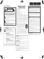
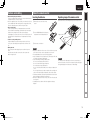
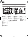
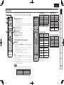
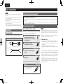
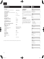
ESPAÑOL
FRANÇAIS
ENGLISH
Integrated Amplifier
PM8004
1.PM8004U_ENG_0701.indd
1
2010/07/01
17:46:08
ESPAÑOL
nSAFETY PRECAUTIONS
CAUTION
RISK OF ELECTRIC SHOCK
DO NOT OPEN
CAUTION:
TO REDUCE THE RISK OF ELECTRIC SHOCK, DO NOT REMOVE
COVER (OR BACK). NO USER-SERVICEABLE PARTS INSIDE.
REFER SERVICING TO QUALIFIED SERVICE PERSONNEL.
The lightning flash with arrowhead symbol, within an equilateral
triangle, is intended to alert the user to the presence of
uninsulated “dangerous voltage” within the product’s enclosure
that may be of sufficient magnitude to constitute a risk of
electric shock to persons.
The exclamation point within an equilateral triangle is intended
to alert the user to the presence of important operating
and maintenance (servicing) instructions in the literature
accompanying the appliance.
WARNING:
TO REDUCE THE RISK OF FIRE OR ELECTRIC SHOCK, DO NOT
EXPOSE THIS APPLIANCE TO RAIN OR MOISTURE.
1.
2.
3.
4.
5.
6.
7.
8.
9.
10.
11.
12.
13.
CAUTION:
HOT SURFACE. DO NOT TOUCH.
Hot
surface
mark
The top surface over the internal heat sink may become hot
when operating this product continuously.
Do not touch hot areas, especially around the “Hot surface
mark” and the top panel.
PRECAUTION:
IMPOTANT SAFETY
INSTRUCTIONS
Read these instructions.
Keep these instructions.
Heed all warnings.
Follow all instructions.
Do not use this apparatus near water.
Clean only with dry cloth.
Do not block any ventilation openings.
Install in accordance with the manufacturer’s instructions.
Do not install near any heat sources such as radiators, heat registers,
stoves, or other apparatus (including amplifiers) that produce heat.
Do not defeat the safety purpose of the polarized or grounding-type plug. A
polarized plug has two blades with one wider than the other. A grounding
type plug has two blades and a third grounding prong. The wide blade or the
third prong are provided for your safety. If the provided plug does not fit into
your outlet, consult an electrician for replacement of the obsolete outlet.
Protect the power cord from being walked on or pinched particularly at
plugs, convenience receptacles, and the point where they exit from the
apparatus.
Only use attachments/accessories specified by the manufacturer.
Use only with the cart, stand, tripod, bracket, or table
specified by the manufacturer, or sold with the apparatus.
When a cart is used, use caution when moving the cart/
apparatus combination to avoid injury from tip-over.
Unplug this apparatus during lightning storms or when
unused for long periods of time.
14. Refer all servicing to qualified service personnel.
Servicing is required when the apparatus has been damaged in any way,
such as power-supply cord or plug is damaged, liquid has been spilled or
objects have fallen into the apparatus, the apparatus has been exposed to
rain or moisture, does not operate normally, or has been dropped.
15. Batteries shall not be exposed to excessive heat such as sunshine, fire or
the like.
SURFACE CHAUDE. NE PAS TOUCHER.
La surface supérieure du dissipateur de chaleur peut devenir
chaude si vous utilisez ce produit en continu.
Ne touchez pas les zones chaudes, tout particulièrement vers
l’inscription “Hot surface mark” et le panneau supérieur.
PRECAUCIÓN:
SUPERFICIE CALIENTE. NO TOCAR.
La superficie superior sobre el disipador de calor interno
podría llegar a calentarse al operar este producto de forma
continua.
No toque las áreas calientes, especialmente las situadas
alrededor de la “Hot surface mark” y del panel superior.
CAUTION:
FRANÇAIS
ENGLISH
FCC INFORMATION (For US customers)
1.PRODUCT
This product complies with Part 15 of the FCC Rules. Operation is subject
to the following two conditions: (1) this product may not cause harmful
interference, and (2) this product must accept any interference received,
including interference that may cause undesired operation.
2.IMPORTANT NOTICE: DO NOT MODIFY THIS PRODUCT
This product, when installed as indicated in the instructions contained
in this manual, meets FCC requirements. Modification not expressly
approved by Marantz may void your authority, granted by the FCC, to use
the product.
3.NOTE
This product has been tested and found to comply with the limits for
a Class B digital device, pursuant to Part 15 of the FCC Rules. These
limits are designed to provide reasonable protection against harmful
interference in a residential installation.
This product generates, uses and can radiate radio frequency energy and,
if not installed and used in accordance with the instructions, may cause
harmful interference to radio communications. However, there is no
guarantee that interference will not occur in a particular installation. If this
product does cause harmful interference to radio or television reception,
which can be determined by turning the product OFF and ON, the user
is encouraged to try to correct the interference by one or more of the
following measures:
•Reorient or relocate the receiving antenna.
•Increase the separation between the equipment and receiver.
•Connect the product into an outlet on a circuit different from that to
which the receiver is connected.
•Consult the local retailer authorized to distribute this type of product or
an experienced radio/TV technician for help.
For Canadian customers:
This Class B digital apparatus complies with Canadian ICES-003.
Cet appareil numérique de la classe B est conforme à la norme NMB-003 du
Canada.
To completely disconnect this product from the mains, disconnect the plug
from the wall socket outlet.
The mains plug is used to completely interrupt the power supply to the unit
and must be within easy access by the user.
PRECAUTION:
Pour déconnecter complètement ce produit du courant secteur, débranchez
la prise de la prise murale.
La prise secteur est utilisée pour couper complètement l’alimentation de
l’appareil et l’utilisateur doit pouvoir y accéder facilement.
PRECAUCIÓN:
Para desconectar completamente este producto de la alimentación eléctrica,
desconecte el enchufe del enchufe de la pared.
El enchufe de la alimentación eléctrica se utiliza para interrumpir por completo
el suministro de alimentación eléctrica a la unidad y debe de encontrarse en
un lugar al que el usuario tenga fácil acceso.
I
1.PM8004U_ENG_0701.indd
3
2010/07/01
17:46:09
ENGLISH
FRANÇAIS
ESPAÑOL
nNOTES ON USE / OBSERVATIONS RELATIVES A L’UTILISATION / NOTAS SOBRE EL USO
WARNINGS
AVERTISSEMENTS
ADVERTENCIAS
•Avoid high temperatures.
Allow for sufficient heat dispersion when
installed in a rack.
•Handle the power cord carefully.
Hold the plug when unplugging the cord.
•Keep the unit free from moisture, water, and
dust.
•Unplug the power cord when not using the unit
for long periods of time.
•Do not obstruct the ventilation holes.
•Do not let foreign objects into the unit.
•Do not let insecticides, benzene, and thinner
come in contact with the unit.
•Never disassemble or modify the unit in any way.
•Ventilation should not be impeded by covering
the ventilation openings with items, such as
newspapers, tablecloths or curtains.
•Naked flame sources such as lighted candles
should not be placed on the unit.
•Observe and follow local regulations regarding
battery disposal.
•Do not expose the unit to dripping or splashing
fluids.
•Do not place objects filled with liquids, such as
vases, on the unit.
•Do not handle the mains cord with wet hands.
•When the switch is in the OFF position, the
equipment is not completely switched off from
MAINS.
•The equipment shall be installed near the
power supply so that the power supply is easily
accessible.
•Eviter des températures élevées.
Tenir compte d’une dispersion de chaleur
suffisante lors de l’installation sur une étagère.
•Manipuler le cordon d’alimentation avec
précaution.
Tenir la prise lors du débranchement du cordon.
•Protéger l’appareil contre l’humidité, l’eau et la
poussière.
•Débrancher le cordon d’alimentation lorsque
l’appareil n’est pas utilisé pendant de longues
périodes.
•Ne pas obstruer les trous d’aération.
•Ne pas laisser des objets étrangers dans
l’appareil.
•Ne pas mettre en contact des insecticides, du
benzène et un diluant avec l’appareil.
•Ne jamais démonter ou modifier l’appareil d’une
manière ou d’une autre.
•Ne pas recouvrir les orifices de ventilation avec
des objets tels que des journaux, nappes ou
rideaux. Cela entraverait la ventilation.
•Ne jamais placer de flamme nue sur l’appareil,
notamment des bougies allumées.
•Veillez à respecter les lois en vigueur lorsque
vous jetez les piles usagées.
•L’appareil ne doit pas être exposé à l’eau ou à
l’humidité.
•Ne pas poser d’objet contenant du liquide, par
exemple un vase, sur l’appareil.
•Ne pas manipuler le cordon d’alimentation avec
les mains mouillées.
•Lorsque l’interrupteur est sur la position OFF,
l’appareil n’est pas complètement déconnecté du
SECTEUR (MAINS).
•L’appareil sera installé près de la source
d’alimentation, de sorte que cette dernière soit
facilement accessible.
•Evite altas temperaturas.
Permite la suficiente dispersión del calor cuando
está instalado en la consola.
•Maneje el cordón de energía con cuidado.
Sostenga el enchufe cuando desconecte el
cordón de energía.
•Mantenga el equipo libre de humedad, agua y
polvo.
•Desconecte el cordón de energía cuando no
utilice el equipo por mucho tiempo.
•No obstruya los orificios de ventilación.
•No deje objetos extraños dentro del equipo.
•No permita el contacto de insecticidas, gasolina
y diluyentes con el equipo.
•Nunca desarme o modifique el equipo de
ninguna manera.
•La ventilación no debe quedar obstruida por
haberse cubierto las aperturas con objetos como
periódicos, manteles o cortinas.
•No deberán colocarse sobre el aparato fuentes
inflamables sin protección, como velas
encendidas.
•A la hora de deshacerse de las pilas, respete la
normativa para el cuidado del medio ambiente.
•No exponer el aparato al goteo o salpicaduras
cuando se utilice.
•No colocar sobre el aparato objetos llenos de
líquido, como jarros.
•No maneje el cable de alimentación con las
manos mojadas.
•Cuando el interruptor está en la posición OFF, el
equipo no está completamente desconectado de
la alimentación MAINS.
•El equipo se instalará cerca de la fuente de
alimentación de manera que resulte fácil acceder
a ella.
nCAUTIONS ON INSTALLATION
PRÉCAUTIONS D’INSTALLATION
EMPLAZAMIENTO DE LA INSTALACIÓN
z
z
z
z
Wall
Paroi
Pared
zFor
z
proper heat dispersal, do not install this unit in a confined
space, such as a bookcase or similar enclosure.
•More than 0.3 m (12 in.) is recommended.
•Do not place any other equipment on this unit.
zPour
z
permettre la dissipation de chaleur requise, n’installez
pas cette unité dans un espace confiné tel qu’une bibliothèque
ou un endroit similaire.
•Une distance de plus de 0,3 m (12 po) est recommandée.
•Ne placez aucun matériel sur cet appareil.
zPara
z
la dispersión del calor adecuadamente, no instale este
equipo en un lugar confinado tal como una librería o unidad
similar.
•Se recomienda dejar más de 0,3 m (12 pulg.) alrededor.
•No coloque ningún otro equipo sobre la unidad.
II
1.PM8004U_ENG_0701.indd
4
2010/07/01
17:46:09
ENGLISH
Contents
Accessories·····················································································1
About this manual·········································································1
Main features··················································································2
Cautions on handling·····································································3
About the remote control·····························································3
Inserting the batteries···································································3
Operating range of the remote control ·········································3
Part names and functions·····························································4
Front panel·····················································································4
Rear panel······················································································4
Remote control··············································································5
Before use·······················································································8
Turning the power on····································································8
Turning the power standby····························································8
Turning the power off····································································8
Starting playback···········································································9
Direct playback using a source audio component·························9
Muting sound················································································9
Using headphone set·····································································9
Starting Recording·········································································9
Basic connections··································································6
Connecting P.DIRECT connectors·················································9
Connecting pre out connectors··················································10
Connecting the remote control connectors······························10
w
e
About this manual
nnOperation buttons
The operations described in this manual are based mainly on
remote control operation.
nnSymbols
Advanced operations·························································10
v
Setting Auto standby mode························································10
This symbol indicates a reference page on which
related information is described.
This symbol indicates a supplementary information
and tips for operations.
NOTE
Specifications·········································································12
nnIllustrations
Index···························································································12
Explanation terms Index
Explanation terms· ······························································12
Note that the illustrations in these instructions are for explanation
purposes and may differ from the actual unit.
Specifications
This symbol indicates points to remember operations
or function limitations.
Troubleshooting···································································11
Troubleshooting
Preparations···················································································6
Connecting cables·········································································6
Connecting the audio equipment·················································6
Connecting the speakers·······························································6
Connecting the speakers cables····················································6
Speaker connections·····································································7
Connecting players········································································7
Connecting recorders····································································7
Connecting the power cord··························································8
Advanced connections························································9
qOwner’s manual....................................................................... 1
wPower cord (Cord length: Approx. 1.8 m).................................. 1
eRemote control (RC003PM)..................................................... 1
rR03/AAA batteries.................................................................... 2
Advanced connections Advanced operation
Basic operation· ······································································8
Check that the following parts are supplied with the product.
Basic operation
Getting started········································································1
Accessories
Basic connections
Thank you for purchasing this MARANTZ product. To ensure properoperation, please read this owner’s manual carefully before using the
product.
After reading the manual, be sure to keep it for future reference.
Getting started
Getting started
1
1.PM8004U_ENG_0701.indd
1
2010/07/01
17:46:09
ENGLISH
Main features
Tri-tonecontrol
This unit has a 3-tone control function for adjusting the midrange
sound in addition to the bass and treble sounds so that you can
make a more variable sound adjustment according to source and
system.
All-discretecurrent-feedbackamplifier
Marantz’ proprietary current-feedback circuit, using discrete
components, is adopted in the pre amplifier and power amplifier.
It is a high-speed amplifier using the latest technology developed
for the higher-grade amplifiers.
HDAM-SA3Technology
The V/I converter circuit, which is the key block of the currentfeedback pre-amplifier and power amplifier, is equivalent to the
HDAM-SA3 ampmodule developed for such higher-grade models
as the PM-11S2.
All-Discretecurrent-feedbackphonoequalizer
As a phono equalizer amplifier for MM cartridges, a constant
current-feedback PHONO equalizer of quality equal to that of the
higher-grade model PM-11S2 is used.
Double-shieldedtriodaltransformer
The unit is equipped with a toroidal power transformer to minimize
vibration and leakage flux specific to the transformer.
Especially to reduce leakage flux, which affects sound quality, the
periphery is double-shielded, using a core ring and a short ring.
Blockcondenseroflargecapacity
A large-capacity condenser of 18,000μF is used in the power circuit
of the power amplifier. In the preamplifier, a 4700μF condenser is
used.
High-performancevolume
CDdirectbufferamplifier
An input buffer amplifier exclusive for CD is mounted near the
CD input jacks. This is a high-speed buffer amplifier made with
discrete components, which avoids interference between right
and left channels and can send the signals to the pre-amplifier with
very high fidelity.
Improvedmomentarycurrentsupplyability
Capacitorforhighqualitysound
Double-layeredchassis
High-gradespeakerterminals
It is generally known that the sound quality is not necessarily the
same even if amplifiers have the same specifiations.
Marantz considers the cause to be the power to drive speakers.
The power amplifier of this unit has the ability to momentarily
supply current of 25 A or more to drive speakers strongly.
Short-power-linelayout
For strong momentary current supply, a short power-line layout
unifies the power circuit and output stage of the power amplifier
section.
This layout allows connecting the large-current lines via the shortest
route while to arranging the left and right channels symmetrically.
2
1.PM8004U_ENG_0701.indd
2
2010/07/01
17:46:10
ENGLISH
Inserting the batteries
qRemove the rear cover of the remote
Operating range of the remote control
operate the remote control while pointing it at the remote sensor.
Basic connections
control.
wSet two R03/AAA batteries in the battery
compartment in the indicated direction.
Basic operation
Approx. 16.4ft / 5 m
30°
30°
ePut the rear cover back on.
NOTE
NOTE
The unit may function improperly or the remote control may not
operate if the remote control sensor is exposed to direct sunlight, or
strong artificial light from a fluorescent or infrared light.
Troubleshooting
Specifications
Explanation terms Index
•Replace the batteries with new ones if the unit does not operate
even when the remote control is operated close to the unit.
•The supplied batteries are only for verifying operation.
•Insert the batteries in the proper direction, following the “q” and
“w” marks in the battery compartment.
•To prevent damage or leakage of battery fluid:
•Do not use a new battery with an old one.
•Do not use two different types of batteries.
•Do not attempt to charge dry batteries.
•Do not short-circuit, disassemble, heat or dispose of batteries in
a fire.
•Do not keep the battery in a place exposed to direct sunlight or in
places with extremely high temperatures, such as near a heater.
•If the battery fluid leaks, carefully wipe the fluid off the inside of the
battery compartment and insert new batteries.
•Remove the batteries from the remote control if it will not be used
for a long time.
•Used batteries in accordance with local regulations on battery
disposal.
Advanced connections Advanced operation
•Before turning the power switch on
Check once again that all connections are correct and that there are
no problems with the connection cables.
•Power is supplied to some of the circuitry even when the unit is set
to the standby mode. When leaving home for long periods of time,
be sure to unplug the power cord from the power outlet.
•About condensation
If there is a major difference in temperature between the inside
of the unit and the surroundings, condensation may form on parts
inside the unit, causing the unit to fail to operate properly.
If this happens, let the unit sit for an hour or two with the power off
and wait until there is little difference in temperature before using
the unit.
•Cautions on using mobile phones
Using a mobile phone near this unit may result in noise. If that
occurs, move the mobile phone away from the unit when it is in
use.
•Moving the unit
Turn off the power and unplug the power cord from the power
outlet.
Next, disconnect the cables connected to other system units
before moving the unit.
About the remote control
Getting started
Cautions on handling
3
1.PM8004U_ENG_0701.indd
3
2010/07/01
17:46:11
ENGLISH
Part names and functions
For buttons not explained here, see the page indicated in parentheses ( ).
Rear panel
Front panel
q
w
e
r
Q5
Q4
Q3 Q2
qPower switch (ON/OFF)································ (8)
wSTANDBY indicator······································· (8)
Indicates the status of the unit’s as follows:
•Power “ON” : Off
•When the protection circuit is activated :
Red (blinking)............................................... (6)
•Standby : Red
•Power “OFF” : Off
eINPUT SELECTOR knob································ (9)
rInput indicators············································· (8)
tMUTE indicator (MUTE)································ (9)
yVOLUME control knob······························ (8, 9)
uRemote control sensor··························· (3, 10)
iBALANCE control knob····························· (8, 9)
oSOURCE DIRECT switch/indicator·············· (9)
Q0TREBLE control knob································ (8, 9)
Q1POWER AMP DIRECT switch/indicator······· (9)
Q1 Q0
o
q we
y
t
i
u
Q2 Q1 Q0 o
Q2MID control knob······································· (8, 9)
Q3SPEAKERS A/B switch/indicators··············· (9)
Q4BASS control knob···································· (8, 9)
Q5Headphone jack (PHONES)··························· (9)
NOTE
You can adjust the i BALANCE, Q0 TREBLE,
MID and Q4 BASS control knobs only when
SOURCE DIRECT switch is turned off.
r
y
u
i
qPHONO input connectors····························· (7)
wPHONO GND terminal··································· (7)
ePRE OUT connectors··································· (10)
rPOWER AMP DIRECT IN connectors··········· (9)
tSpeaker system terminals
(SPEAKERES SYSTEM A/B)····················· (6, 7)
Q2
o
t
yREMOTE CONTROL
input/output connectors···························· (10)
uAC inlet (AC IN)·············································· (8)
iRECORDER 2
input/output connectors······························ (7)
oRECORDER 1
input/output connectors······························ (7)
Q0AUX/DVD input connectors························· (7)
Q1TUNER input connectors······························ (7)
Q2CD input connectors····································· (7)
4
1.PM8004U_ENG_0701.indd
4
2010/07/01
17:46:11
ENGLISH
Remote control
w
qPOWER ON/STANDBY buttons················································ (8)
t
r
•MUTE Button
•VOLUME + / – Button
nnOperating Marantz audio components
t
Operation
8 9
2
1
3
0–9
T.MODE
Skip
Stop
Playback
Pause
Track selection
Sound mode selection
Operation
buttons
8 9
2
1
3
MENU
d f 0 1
ENTER
0–9
DISPLAY
Function
Skip
Stop
Playback
Pause
Menu
Cursor operation
Enter setting
Enter number
Display disc
information
nnTuner operation
Operation
buttons
P.SCAN/A.TUNE
d/TUNE+
f/TUNE–
Function
Operation
buttons
Function
8
9
2
1
3
CLEAR
Fast-rewind
Fast-forward
Stop
Playback
Pause
Counter reset
Explanation terms Index
preset scan
Tuning up
Tuning down
Preset channel
0/PRESET–
selection
Preset channel
1/PRESET+
selection
BAND
FM/AM switching
0–9
Enter number
Clear memory
CLEAR
or input data
Save preset
MEMO
station number
Direct frequency
F.DIRECT
tuning
Auto stereo/
T.MODE
monaural switching
•The remote control buttons may
not function properly for some
Marantz tuners.
nnCassette deck operation
Specifications
•The remote control e Input selector buttons are used to select the
input source for this unit and switch the remote control operation
mode at the same time.
•You can operate the remote control of this unit regardless of the
remote control mode setting.
•To use the remote control correctly, also refer to the operating
instructions of other components.
Function
Troubleshooting
1Press the corresponding e Input selector button of the audio
component for selecting the input source to be used in playback
and recording.
•The remote control operation is switched to operation mode of the
selected input source.
•This unit’s function will be switched accordingly.
2Operate the audio component.
•See the table on the right for the buttons you can use.
Operation
buttons
Advanced connections Advanced operation
wSOURCE DIRECT button···························································· (9)
eInput selector buttons······························································· (5)
y rINPUT d/f buttons···································································· (9)
tComponent operating buttons
yVOLUME adjustment buttons··············································· (8, 9)
nnDVD operation
Basic operation
e
•POWER ON button
•POWER OFF button
•SOURCE POWER button
You can press this button to switch the mode of Marantz audio
components (provided with a power standby function) between
power-on and standby.
nnCD operation
Basic connections
You can use the supplied remote control to operate this unit and
Marantz audio components such as CD players, tuners, DVD players,
and tape decks. See “Operating Marantz audio components”(vpage
5).
q
Getting started
Part names and functions
NOTE
Some input terminals of this unit and corresponding input selector
buttons on the remote control have different names, as shown below.
Remote control buttons The unit input terminals
AUX, DVD
AUX/DVD
CD-R
RECORDER1
TAPE, MD
RECORDER2
5
1.PM8004U_ENG_0701.indd
5
2010/07/01
17:46:11
ENGLISH
Basic connections
NOTE
•Do not plug in the power cord until all connections have been
completed.
•When making connections, also refer to the operating instructions
of the other components.
•Be sure to connect the left and right channels properly (left with
left, right with right).
•Do not bundle power cords with connection cables. Doing so can
result in humming or noise.
•Do not turn up the volume without a turntable connected to the
PHONO input terminals. Doing so will cause humming or noise.
Cautions on playing SA(Super Audio) sources:
When regular speakers not compatible with SA sources (DVD Audio discs, Super Audio CDs and other sources, including treble components
above the audible range), set the properties of the player (DVD Audio player, Super Audio CD player, etc.) for use with regular speakers (or
amplifiers).
The speakers may be damaged if the volume is set too high when playing SA sources. For instructions on player settings, refer to the
operating instructions included with the player.
Connecting the speakers
Connecting the speakers cables
Preparations
Carefully check the left (L) and right (R) channels and + (red) and –
(white) polarities on the speakers being connected to the unit, and be
sure to connect the channels and polarities correctly.
Connecting cables
Select the cables according to the equipment being connected.
Audio cables
off about 10 mm of sheathing
1 Peel
from the tip of the speaker cable,
then either twist the core wire tightly
or apply solder to it.
Analog connections (stereo)
(L)
(R)
Connecting the audio equipment
L
L
R
R
the speaker terminal
2 Turn
counterclockwise to loosen it.
Stereo pin-plug cable
Speaker connections
the speaker cable’s core
3 Insert
wire to all the way into the speaker
Speaker cables
terminal.
the speaker terminal clockwise
4 Turn
to tighten it.
NOTE
•Connect the speaker cables so they do not stick out of the speaker
terminals. The protection circuit may be activated if the wires touch
the rear panel or if the + and – sides touch each other (“Protection
circuit”).
•Never touch the speaker terminals while the power supply is
connected. Doing so could result in electric shock.
nnProtection circuit
The protection circuit is be activated in the following situations:
•If the speaker cable wire touches the rear panel or screws or if
the speaker cable wire touches the speaker cable’s + and – sides
are touching
•If the surrounding temperature is extremely high
•If the inside of the amplifier gets hot to extended use at a high
output
If the protection circuit is activated, the speaker output is blocked
and the power indicator flashes in red. If this happens, unplug the
power cord, then check the connections of the speaker cables and
input cables. If the unit becomes very hot, wait for it to cool off and
improve the ventilation around it. After doing this, plug the power
cord back in.
If the protection circuit is activated even though there are no
problems with the ventilation around the unit or in connections,
the unit may be damaged. Turn off the power and then contact a
Marantz service center.
When using a banana plug
Tighten the speaker terminal
firmly before inserting the banana
plug.
6
1.PM8004U_ENG_0701.indd
6
2010/07/01
17:46:12
ENGLISH
Speaker connections
Speakers A
(R)
q
w
Turntable
Speakers B
(L)
q
w
Connect the ground wire from your turntable here.
(R)
q
w
Basic operation
(L)
w
A turntable with an MM type cartridge can be connected to this unit. To use an MC cartridge, please
install a step-up transformer.
•If humming or other noise is generated when the ground wire is connected, disconnect it.
Basic connections
•The same signal is output from the SPEAKERS A and B terminals.
•When only one set of speakers is to be connected, use either the SYSTEM A or B terminals.
Connecting players
Getting started
Connecting the speakers
q
AUDIO
OUT
GND
Tuner
AUDIO
L
R
L
L
R
R
Advanced connections Advanced operation
AUDIO OUT
L
R
DVD player
CD player
AUDIO
AUDIO
AUDIO OUT
AUDIO OUT
nnSpeaker impedance
Use speakers with impedances within the ranges shown below to suit how they are used.
Impedance
4 - 16 Ω
4 - 16 Ω
8 - 16 Ω
L
L
L
L
L
R
R
R
R
R
Connecting recorders
Recorder-2
Recorder-1
AUDIO
AUDIO
L
R
R
L
R
L
L
L
R
R
R
L
L
L
R
R
R
AUDIO OUT
AUDIO OUT
R
L
R
L
R
Explanation terms Index
L
Specifications
AUDIO IN
AUDIO IN
L
Troubleshooting
Speakers used
A
B
A and B
L
R
7
1.PM8004U_ENG_0701.indd
7
2010/07/01
17:46:13
ENGLISH
Connecting the power cord
Wait until all connections have been completed before connecting the
power cord.
To household power
outlet
(AC 120 V, 60 Hz)
Power cord
(supplied)
Basic operation
Symbolsusedtoindicatebuttonsinthismanual
Button located on both the main unit and
the remote control
Button only on the main unit
Button only on the remote control
BUTTON
<BUTTON>
[BUTTON]
Before use
1 Turn the VOLUME all the way down.
Set <BASS>, <MID>, <TREBLE> and <BALANCE> to
2 the
center positions.
<INPUT SELECTOR>
<POWER AMP DIRECT>
VOLUME
Input indicators
<SPEAKERS A/B>
SOURCE DIRECT
Turning the power on
Press <ON/OFF>.
NOTE
• Power is turned on.
• Input indicator for the selected source lights.
• The unit will be ready to start playback after several seconds.
• Insert the plugs securely. Loose connections will result in the
generation of noise.
• Do not use any cord other than the provided power cord.
STANDBY
indicator <ON/OFF> <BASS>
<TREBLE> <BALANCE>
PHONES jack <MID>
Turning the power standby
Press [POWER OFF].
• The power is set to the standby mode.
• The STANDBY indicator lights in red.
[POWER OFF]
SOURCE DIRECT
[POWER ON]
• Press [POWER ON] to turn on power from standby mode.
• You can also turn on power by using either <INPUT SELECTOR>
from standby mode.
NOTE
[INPUTd,f]
VOLUME
Power continues to be supplied to some of the circuitry even when the
power is in the standby mode. When leaving home for long periods of
time or when going on vacation, either press <ON/OFF> to turn off the
power, or unplug the power cord from the power outlet.
[MUTE]
Turning the power off
Press <ON/OFF>.
• Power is turned off.
• All indicators will turn off.
8
1.PM8004U_ENG_0701.indd
8
2010/07/01
17:46:13
ENGLISH
1
Use either <INPUT SELECTOR> or [INPUT d,f] to
select an input source you want for playback.
PHONO
TUNER
CD
AUX/DVD
RECORDER-1
RECORDER-2
The indicator for the selected speaker system lights.
3
4 Adjust the VOLUME to the desired level.
Start playing back the source.
nnAdjusting the tone
Adjusts the bass sound.
Adjusts the midrange sound.
Adjusts the treble sound.
Adjusts the left and right output balance.
Adjust the VOLUME to the desired level.
•Switching <POWER AMP DIRECT> “ON”, allows the device
connected to the Power Amp Direct connector on the rear panel to
be played. When ON, the input indicator turns off.
•Switching <POWER AMP DIRECT> “OFF”, allows the program
source selected using the INPUT SELECTOR knob to be played.
When OFF, the input indicator lights up.
For details on operations of the preamplifier, refer to the instruction
manual supplied with the preamplifier to be used.
NOTE
Pre-amplifier
To prevent hearing loss, do not raise the volume level excessively
when using headphones.
Speaker
(L)
Speaker
(R)
(L)
(R)
Starting Recording
1 select the input source you want to record.
2 Set the recorder to recording mode.
3 Start playback of the source you want to record.
R
Use either <INPUT SELECTOR> or [INPUT d,f] to
R
L
To PRE OUT
connectors
w
q w
q
L
•Recording will start in sync with the playback operation of the
source.
Press SOURCE DIRECT.
The SOURCE DIRECT indicator lights.
To adjust the tone, turn off SOURCE DIRECT.
NOTE
•When the POWER AMP DIRECT is “ON”, adjustment of the
volume, balance and tone on the main unit has no effect. Adjust the
volume on the input device.
•When the POWER AMP DIRECT is “ON”, the main unit outputs
at maximum volume. Check the output level on the input device
before playing it and adjust the volume accordingly.
Explanation terms Index
Since the audio signals bypass the tone control circuits (BASS/MID/
TREBLE/BALANCE), the music reproduction is more faithful to the
original sound.
nnAdjusting the volume
To switch the POWER AMP DIRECT mode, press and
hold <POWER AMP DIRECT> for at least 3 seconds.
Specifications
Direct playback using a source audio
component
Plug headphones into PHONES jack.
•To listen with headphones, turn speaker output OFF.
If you use a preamplifier, connect it as shown below, and then you
can use this unit as a power amplifier.
Troubleshooting
• <BASS>
• <MID>
• <TREBLE>
• <BALANCE>
Using headphone set
Connecting P.DIRECT connectors
Advanced connections Advanced operation
<SPEAKERS A/B> to select the speaker system
2 toPress
be used for playback.
The MUTE indicator lights.
•To cancel the mute operation, press the button again.
You can also cancel the mute operation by operating VOLUME of
the remote control.
Basic operation
•You can also select an input source by pressing the Input selector
buttons of the remote control.
•The input source you select is stored in memory even after you turn
off power, and the same source is selected when power is turned
on again.
Press [MUTE].
Advanced connections
Basic connections
The input indicator for the selected source lights.
GSelectable sourcesH
This function mutes the sound by stopping audio output.
Getting started
Muting sound
Starting playback
9
1.PM8004U_ENG_0701.indd
9
2010/07/01
17:46:14
ENGLISH
Connecting pre out connectors
If you use a power amplifier, connect it as shown below, and then
you can use this unit as a preamplifier.
For connecting speaker systems, refer to the instruction manual
supplied with the power amplifier to be used.
Power-amplifier
Connecting the remote control connectors
When you use this unit connected to Marantz audio components, it
sends control signals to operate each component.
nnConnection
Use the remote connection cable (supplied with a Marantz
audio component you want to connect) to connect the REMOTE
CONTROL OUT terminal of this unit to the REMOTE CONTROL IN
terminal of the component to be connected.
Advanced operations
Setting Auto standby mode
With the Auto standby mode ON, this unit will automatically enter
the Auto standby mode after about 30 continuous minutes of no
output from the speakers or headphones.
SOURCE DIRECT
nnSetting
L
R
To input
connectors
L
R
Set the remote control switch located on the rear panel of the
connected audio component to “EXTERNAL” or “EXT.” to use
this feature.
•This setting will disable remote sensor reception of the connected
audio component.
•To operate the connected audio component, point the remote
control at the remote sensor of this unit.
Press and hold <SOURCE DIRECT> for at least 5 seconds.
•Auto standby mode is switched between On and Off.
Auto standby mode “Off”
Power indicator
Flashes once
Auto standby mode “On”
Power indicator
Flashes three times
NOTE
Perform the operation using the buttons on the unit. You cannot
perform the operation using [SOURCE DIRECT] on the remote control.
NOTE
•NEVER insert the short-circuiting pin plug into the PRE OUT
terminals. Doing so could result in damage.
•Signals are output from the PRE OUT terminals even when using
headphones.
INPUT
IN
•The default setting for the Auto standby mode is OFF.
•This unit will automatically enter Auto standby mode after about
continuous 30 minutes in the following conditions.
•No output from the selected input source.
•No operation performed on the remote control.
•No operation of <SPEAKERS A/B>, <POWER AMP DIRECT>,
<SOURCE DIRECT> or <INPUT SELECTOR>.
OUTPUT
OUT
REMOTE CONTROL
CD player
RC OUT
Option unit
(such as remote control receiver unit)
10
1.PM8004U_ENG_0701.indd
10
2010/07/01
17:46:14
ENGLISH
Getting started
Troubleshooting
Symptom
Countermeasure
Page
•Make sure that the power cord is plugged in properly.
•Either turn the INPUT SELECTOR knob of this unit or press POWER ON of the remote
control.
•If the STANDBY indicator is blinking, turn off power, wait 1 minute or longer, and turn on
power again.
8
8
7
7
9
9
9
•The mute function activated.
•Make sure the speakers are connected properly.
•Make sure the input cables are connected properly.
•Set the INPUT SELECTOR knob at the correct setting position.
•Use the VOLUME control knob to turn volume up to an appropriate level.
•Turn on the SPEAKERS A/B switch corresponding to the speaker system terminals (SYSTEM
A or SYSTEM B) to which the speakers are connected.
•Turn on the SPEAKERS A/B switch corresponding to the speaker system terminals (SYSTEM
A or SYSTEM B) to which the speakers are connected.
•If the MUTE indicator is lit, press MUTE on the remote control to cancel muting.
•The protection circuit is activated.
•Turn off power, wait 1 minute or longer, and turn on power again.
6
•The power cord’s plug is not plugged in firmly.
•The unit is in standby mode.
•The protection circuit is activated.
•The incorrect SPEAKERS A/B switch is turned on.
The volume drops automatically.
6
9
9
•Make sure that the speakers are connected correctly.
7
Noise is produced during a record •The ground wire from the turntable is disconnected.
•The PHONO input terminals are not properly connected.
playback.
•A TV set near the turntable is causing the noise.
•Make sure that the PHONO GND terminal is connected properly.
•Make sure that the PHONO input terminal is connected properly.
•Relocate the TV set or turntable in another place.
7
7
–
An audio feedback occurs when you •The turntable and speakers are too close to each other.
turn up the volume during a record •The turntable is placed on a rack or floor that vibrates easily.
playback.
•Install the speakers as far away from the turntable as possible.
•If the turntable is not supplied with an insulating pad, use insulating pad available in the
market.
–
–
The unit does not function when a •Batteries are low.
•You are operating the remote control outside of the specified
remote control button is pressed.
range.
•There is an obstacle between the main unit and remote
control.
•You have pressed the wrong button.
•Batteries are not inserted in the proper direction as indicated
by polarity markers (q and w) in the battery compartment.
•Replace with new batteries.
•Operate within the specified range.
3
3
•Remote the obstacle.
3
•Press the correct button.
•Insert the batteries in the proper direction in accordance with the polarity markers in the
battery compartment.
5
3
Explanation terms Index
The left and right channels are
reversed.
Specifications
7
9
Troubleshooting
Sound is produced from either one •The speaker cables are not properly connected.
•Make sure that the speakers are connected properly.
•The BALANCE control knob setting position is inappropriate. •Set the BALANCE control knob at the appropriate position.
speaker only.
•Either the left/right speaker or left/right input cable
connections are reversed.
Advanced connections Advanced operation
When power is turned on but there is •The speaker cables are not properly connected.
no sound.
•The input cable is not properly connected.
•The INPUT SELECTOR knob setting position is incorrect.
•The VOLUME control knob is set to minimum.
•The SPEAKERS A/B switches are turned off.
Basic operation
Power is not turned on.
Cause
Basic connections
If a problem occurs, first check the following:
1.Are the connections correct?
2.Is the unit being operated as described in the owner’s manual?
3.Are the other components operating properly?
If this unit does not operate properly, check the items listed in the table below. If the problem persist there may be a malfunction.
In that case, disconnect the power immediately and contact your retail outlet.
11
1.PM8004U_ENG_0701.indd
11
2010/07/01
17:46:15
ENGLISH
Specifications
•Power output (20 Hz – 20 kHz simultaneous drive of both channels):
•Total harmonic distortion (20Hz – 20kHz simultaneous drive of both channels, 8Ω load):
•Output band width (8Ω load, 0.05%):
•Frequency response (CD, 1W, 8Ω load):
•Dumping factor (8Ω load, 20Hz – 20kHz):
•Input sensitivity/Input impedance
PHONO (MM):
CD, TUNER, AUX/DVD, RECORDER:
POWER AMP DIRECT IN
•Output voltage/Output impedance
PRE OUT
•Maximum allowable PHONO input level (1kHz)
MM •RIAA deviation (20Hz ~ 20kHz)
•S/N (IHF-A, 8Ω load)
PHONO (MM)
CD, TUNER, AUX/DVD, RECORDER
POWER AMP DIRECT IN .
•Tone control
Bass (50Hz)
Mid (900Hz)
Treble (15kHz)
•Power requirement
•Power consumption
(UL60065) Standby power consumption
•Weight
Explanation terms
70 W x 2 (8 Ω load)
100 W x 2 (4 Ω load)
0.02%
5Hz – 60kHz
5Hz – 100kHz ±3dB
100
2mV/47kΩ
200mV/20kΩ
1.6V/15kΩ
1.6V/600Ω
100mV
±0.5dB
87dB (5mV input, 1W output)
106dB (2V input, Rated output)
125dB (Rated output)
±10dB
±6dB
±10dB
AC 120V 60Hz
200W
0.3W
26.9 lbs (12.2kg)
P
Protection Circuit
This is a function to prevent damage to components
within the power supply when an abnormality such
as an overload or excess voltage occurs for any
reason.
In this unit, the STANDBY indicator blinks and the
unit enters standby mode when an abnormality
occurs.
S
Speaker impedance
This is certain-rated resistance of the speaker set
to an alternating current and expressed in ohms.
The smaller the impedance, the greater the output.
However, load on the amplifier is increased. Use
speakers whose impedance is supported by this
unit.
Index
vvA
Adjusting the tone················································· 9
Adjusting the volume············································ 9
Auto standby mode············································· 10
vvB
BALANCE·························································· 4, 8
BASS································································· 4, 8
Batteries································································ 3
Before use····························································· 8
vvC
Connection
Connecting cables·············································· 6
Connecting players············································· 7
Connecting recorders········································· 7
Connecting the speakers································ 6, 7
vvI
INPUT SELECTOR············································· 4, 8
vvM
MID··································································· 4, 8
Mute·································································· 4, 8
vvP
POWER AMP DIRECT······································ 4, 9
Power cord···························································· 8
PRE OUT························································· 4, 10
Protection circuit············································· 6, 12
vvR
Remote control··········································· 3, 5, 10
For the purpose of improvement, the specifi cations and design are subject to change without notice.
vvS
SOURCE DIRECT·············································· 4, 8
Speaker cables·················································· 6, 7
Stereo pin-plug cable············································· 6
vvT
TREBLE····························································· 4, 8
vvV
VOLUME··························································· 4, 8
12
1.PM8004U_ENG_0701.indd
12
2010/07/01
17:46:15
11/16
(16.5)
4.PM8004U_Backpage.indd
23
3/4
(17.5)
17 3/8 (440)
5 1/8 (130)
4 1/2 (113.5)
14 15/16 (379)
12 15/16 (328.5)
1 5/16
(33)
•PM8004 (unit: inchs (mm))
2010/07/01
17:49:13
D&M Holdings Inc.
Printed in China 5411 10491 028M
4.PM8004U_Backpage.indd
24
2010/07/01
17:49:13