1
Agilent 75000 Series B
Agilent E1346A
48-Channel Relay Multiplexer
Service Manual
Enclosed is the Service Manual for the Agilent E1346A
48-Channel Relay Multiplexer. Insert this manual, along
with any other VXIbus manuals that you have, into the binder
that came with your Agilent Technologies mainframe.
*E1346-90011*
Manual Part Number: E1346-90011
Printed in Malaysia E0706
Certification
Agilent Technologies certifies that this product met its published specifications at the time of shipment from the factory. Agilent
Technologies further certifies that its calibration measurements are traceable to the United States National Institute of Standards and
Technology (formerly National Bureau of Standards), to the extent allowed by that organization’s calibration facility, and to the calibration
facilities of other International Standards Organization members.
Warranty
This Agilent Technologies product is warranted against defects in materials and workmanship for a period of one (1) year from date of
shipment. Duration and conditions of warranty for this product may be superseded when the product is integrated into (becomes a part
of) other Agilent products. During the warranty period, Agilent Technologies will, at its option, either repair or replace products which
prove to be defective.
For warranty service or repair, this product must be returned to a service facility designated by Agilent Technologies. Buyer shall prepay
shipping charges to Agilent and Agilent shall pay shipping charges to return the product to Buyer. However, Buyer shall pay all shipping
charges, duties, and taxes for products returned to Agilent from another country.
Agilent warrants that its software and firmware designated by Agilent for use with a product will execute its programming instructions
when properly installed on that product. Agilent does not warrant that the operation of the product, or software, or firmware will be
uninterrupted or error free.
Limitation Of Warranty
The foregoing warranty shall not apply to defects resulting from improper or inadequate maintenance by Buyer, Buyer-supplied products
or interfacing, unauthorized modification or misuse, operation outside of the environmental specifications for the product, or improper site
preparation or maintenance.
The design and implementation of any circuit on this product is the sole responsibility of the Buyer. Agilent does not warrant the Buyer’s
circuitry or malfunctions of Agilent products that result from the Buyer’s circuitry. In addition, Agilent does not warrant any damage that
occurs as a result of the Buyer’s circuit or any defects that result from Buyer-supplied products.
NO OTHER WARRANTY IS EXPRESSED OR IMPLIED. Agilent SPECIFICALLY DISCLAIMS THE IMPLIED WARRANTIES
OF MERCHANTABILITY AND FITNESS FOR A PARTICULAR PURPOSE.
Exclusive Remedies
THE REMEDIES PROVIDED HEREIN ARE BUYER’S SOLE AND EXCLUSIVE REMEDIES. Agilent SHALL NOT BE LIABLE
FOR ANY DIRECT, INDIRECT, SPECIAL, INCIDENTAL, OR CONSEQUENTIAL DAMAGES, WHETHER BASED ON CONTRACT, TORT, OR ANY OTHER LEGAL THEORY.
Notice
The information contained in this document is subject to change without notice. Agilent Technologies MAKES NO WARRANTY OF
ANY KIND WITH REGARD TO THIS MATERIAL, INCLUDING, BUT NOT LIMITED TO, THE IMPLIED WARRANTIES OF
MERCHANTABILITY AND FITNESS FOR A PARTICULAR PURPOSE. Agilent shall not be liable for errors contained herein or for
incidental or consequential damages in connection with the furnishing, performance or use of this material. This document contains
proprietary information which is protected by copyright. All rights are reserved. No part of this document may be photocopied, reproduced,
or translated to another language without the prior written consent of Agilent Technologies, Inc. Agilent assumes no responsibility for the
use or reliability of its software on equipment that is not furnished by Agilent.
U.S. Government Restricted Rights
The Software and Documentation have been developed entirely at private expense. They are delivered and licensed as "commercial
computer software" as defined in DFARS 252.227- 7013 (Oct 1988), DFARS 252.211-7015 (May 1991) or DFARS 252.227-7014 (Jun
1995), as a "commercial item" as defined in FAR 2.101(a), or as "Restricted computer software" as defined in FAR 52.227-19 (Jun 1987)(or
any equivalent agency regulation or contract clause), whichever is applicable. You have only those rights provided for such Software and
Documentation by the applicable FAR or DFARS clause or the Agilent standard software agreement for the product involved.
Agilent E1346A 48-Channel Relay Multiplexer Module Service Manual
Edition 2 Rev 2
Copyright © 1996-2006 Agilent Technologies, Inc. All Rights Reserved.
i
Printing History
The Printing History shown below lists all Editions and Updates of this manual and the printing date(s). The first printing of the manual
is Edition 1. The Edition number increments by 1 whenever the manual is revised. Updates, which are issued between Editions, contain
replacement pages to correct the current Edition of the manual. Updates are numbered sequentially starting with Update 1. When a new
Edition is created, it contains all the Update information for the previous Edition. Each new Edition or Update also includes a revised copy
of this printing history page. Many product updates or revisions do not require manual changes and, conversely, manual corrections may
be done without accompanying product changes. Therefore, do not expect a one-to-one correspondence between product updates and
manual updates.
Edition 1 (Part Number E1346-90010). . . . . . . . . . . . . . . . . . . . . . . . . May 1992
Edition 2 (Part Number E1346-90011). . . . . . . . . . . . . . . . . . . . . . . . . May 1996
Edition 2 Rev 2 (Part Number E1346-90011) . . . . . . . . . . . . . . . . . . . July 2006
Safety Symbols
Instruction manual symbol affixed to product.
Indicates that the user must refer to the manual for specific WARNING or CAUTION
information to avoid personal injury or damage to the product.
Alternating current (AC).
Direct current (DC).
Indicates hazardous voltages.
Indicates the field wiring terminal that must
be connected to earth ground before operating
the equipment—protects against electrical
shock in case of fault.
or
WARNING
Frame or chassis ground terminal—typically
connects to the equipment’s metal frame.
CAUTION
Calls attention to a procedure, practice, or condition that could cause bodily injury or death.
Calls attention to a procedure, practice, or condition that could possibly cause damage to
equipment or permanent loss of data.
WARNINGS
The following general safety precautions must be observed during all phases of operation, service, and repair of this product.
Failure to comply with these precautions or with specific warnings elsewhere in this manual violates safety standards of design,
manufacture, and intended use of the product. Agilent Technologies assumes no liability for the customer’s failure to comply with
these requirements.
Ground the equipment: For Safety Class 1 equipment (equipment having a protective earth terminal), an uninterruptible safety earth
ground must be provided from the mains power source to the product input wiring terminals or supplied power cable.
DO NOT operate the product in an explosive atmosphere or in the presence of flammable gases or fumes.
For continued protection against fire, replace the line fuse(s) only with fuse(s) of the same voltage and current rating and type.
DO NOT use repaired fuses or short-circuited fuse holders.
Keep away from live circuits: Operating personnel must not remove equipment covers or shields. Procedures involving the removal of
covers or shields are for use by service-trained personnel only. Under certain conditions, dangerous voltages may exist even with the
equipment switched off. To avoid dangerous electrical shock, DO NOT perform procedures involving cover or shield removal unless you
are qualified to do so.
DO NOT operate damaged equipment: Whenever it is possible that the safety protection features built into this product have been
impaired, either through physical damage, excessive moisture, or any other reason, REMOVE POWER and do not use the product until
safe operation can be verified by service-trained personnel. If necessary, return the product to an Agilent Technologies Sales and Service
Office for service and repair to ensure that safety features are maintained.
DO NOT service or adjust alone: Do not attempt internal service or adjustment unless another person, capable of rendering first aid and
resuscitation, is present.
DO NOT substitute parts or modify equipment: Because of the danger of introducing additional hazards, do not install substitute parts
or perform any unauthorized modification to the product. Return the product to an Agilent Technologies Sales and Service Office for
service and repair to ensure that safety features are maintained.
ii
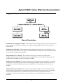
Agilent 75000 Series B Service Documentation
Suggested Sequence to Use Manuals
Manual Descriptions
Installation and Getting Started Guide. This manual contains step-by-step instructions for all aspects of
plug-in module and mainframe installation. Introductory programming information and examples are
also included.
Mainframe User’s Manual. This manual contains programming information for the mainframe, front
panel operation information (for the Agilent E1301B mainframe), and general programming information
for instruments installed in the mainframe.
Plug-In Module User’s Manuals. These manuals contain plug-in module programming and
configuration information. Each manual contains examples for the most-used module functions, and a
complete SCPI command reference for the plug-in module.
Mainframe Service Manual. This manual contains service information for the mainframe. It contains
information for ordering replaceable parts and exchanging assemblies. Information and procedures for
performance verification, adjustment, preventive maintenance, troubleshooting, and repair are also
included.
Plug-In Module Service Manuals. These manuals contain plug-in module service information. Each
manual contains information for exchanging the module and/or ordering replaceable parts. Depending
on the module, information and procedures for functional verification, operation verification,
performance verification, adjustment, preventive maintenance, troubleshooting, and repair are also
provided.
iii
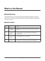
What’s in this Manual
Manual Overview
This manual shows how to service the Agilent E1346A Single Ended Relay Multiplexer. Consult the
Agilent E1346A User’s Manual for additional information on installing, configuring, and operating the
Agilent E1346A. Consult the appropriate mainframe user’s manual for information on configuring and
operating the mainframe.
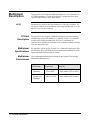
Manual Content
Chap
Title
Content
1
General
Information
Provides a basic description and lists the test equipment required for
service.
2
Verification
Tests
Functional verification, operation verification, and performance
verification tests.
3
Replaceable
Parts
Lists replaceable parts for the multiplexers.
4
Service
Procedures to aid in fault isolation and repair of the multiplexers.
iv
Contents
Chapter 1 - General Information
Introduction . . . . . . . . . . . . . . . . . . . . . . . . . . . . . . . . . . . . . . . . . . . . . . . . . . . . 1-1
SafetyConsiderations . . . . . . . . . . . . . . . . . . . . . . . . . . . . . . . . . . . . . . . . . . . . . . . 1-2
Warnings . . . . . . . . . . . . . . . . . . . . . . . . . . . . . . . . . . . . . . . . . . . . . . . . . . . 1-2
Cautions . . . . . . . . . . . . . . . . . . . . . . . . . . . . . . . . . . . . . . . . . . . . . . . . . . . . 1-3
RelayLife . . . . . . . . . . . . . . . . . . . . .
Loading and Switching FrequencyEffects .
End of Life Detection . . . . . . . . . . . .
Replacement Strategy . . . . . . . . . . . .
.
.
.
.
.
.
.
.
.
.
.
.
.
.
.
.
.
.
.
.
.
.
.
.
.
.
.
.
.
.
.
.
.
.
.
.
.
.
.
.
.
.
.
.
.
.
.
.
.
.
.
.
.
.
.
.
.
.
.
.
.
.
.
.
.
.
.
.
.
.
.
.
.
.
.
.
.
.
.
.
.
.
.
.
.
.
.
.
.
.
.
.
.
.
.
.
.
.
.
.
.
.
.
.
.
.
.
.
.
.
.
.
.
.
.
.
.
.
.
.
.
.
.
.
. 1-4
. 1-4
. 1-4
. 1-5
Multiplexer Description . . . . . . . . . . . . . . . . . . . . . . . .
Agilent E1346A Description . . . . . . . . . . . . . . . . . . .
Multiplexer Specifications . . . . . . . . . . . . . . . . . . . . .
Multiplexer Environment . . . . . . . . . . . . . . . . . . . . .
Multiplexer Serial Numbers . . . . . . . . . . . . . . . . . . . .
Multiplexer Options . . . . . . . . . . . . . . . . . . . . . . . .
Schematics/Component Locators . . . . . . . . . . . . . . . . .
.
.
.
.
.
.
.
.
.
.
.
.
.
.
.
.
.
.
.
.
.
.
.
.
.
.
.
.
.
.
.
.
.
.
.
.
.
.
.
.
.
.
.
.
.
.
.
.
.
.
.
.
.
.
.
.
.
.
.
.
.
.
.
.
.
.
.
.
.
.
.
.
.
.
.
.
.
.
.
.
.
.
.
.
.
.
.
.
.
.
.
.
.
.
.
.
.
.
.
.
.
.
.
.
.
.
.
.
.
.
.
.
.
.
.
.
.
.
.
.
.
.
.
.
.
.
.
.
.
.
.
.
.
.
.
.
.
.
.
.
. 1-6
. 1-6
. 1-6
. 1-6
. 1-7
. 1-7
. 1-7
Recommended Test Equipment . . . . . . . . . . . . . . . . . . . . . . . . . . . . . . . . . . . . . . . . . 1-8
Inspection/Shipping . . . . . . . . . . . . . . . . . . . . . . . . . . . . . . . . . . . . . . . . . . . . . . . . 1-8
Initial Inspection . . . . . . . . . . . . . . . . . . . . . . . . . . . . . . . . . . . . . . . . . . . . . . . 1-8
Shipping Guidelines . . . . . . . . . . . . . . . . . . . . . . . . . . . . . . . . . . . . . . . . . . . . . 1-10
Chapter 2 - Verification Tests
Introduction . . . . . . . . . . . .
Test Conditions/Procedures .
Performance Test Record . .
Verification Test Examples .
.
.
.
.
.
.
.
.
.
.
.
.
.
.
.
.
.
.
.
.
.
.
.
.
.
.
.
.
.
.
.
.
.
.
.
.
.
.
.
.
.
.
.
.
.
.
.
.
.
.
.
.
.
.
.
.
.
.
.
.
.
.
.
.
.
.
.
.
.
.
.
.
.
.
.
.
.
.
.
.
.
.
.
.
.
.
.
.
.
.
.
.
.
.
.
.
.
.
.
.
.
.
.
.
.
.
.
.
.
.
.
.
.
.
.
.
.
.
.
.
.
.
.
.
.
.
.
.
.
.
.
.
.
.
.
.
.
.
.
.
.
.
.
.
.
.
.
.
.
.
.
.
.
.
.
.
. 2-1
. 2-1
. 2-1
. 2-1
Functional Verification Test . . . . . . . . . . . . . . . . . . . . . . . . . . . . . . . . . . . . . . . . . . . 2-2
Procedure . . . . . . . . . . . . . . . . . . . . . . . . . . . . . . . . . . . . . . . . . . . . . . . . . . . 2-2
Example . . . . . . . . . . . . . . . . . . . . . . . . . . . . . . . . . . . . . . . . . . . . . . . . . . . . 2-2
Operation Verification Test . . . . . . . . . . . . . . . . . . . . . . . . . . . . . . . . . . . . . . . . . . . 2-2
Performance Verification Tests . . . . . . . .
Wiring the Test Fixture . . . . . . . . . .
Test 2-1: Closed Channel Resistance Test
Test 2-2: DC Isolation Test . . . . . . . .
.
.
.
.
.
.
.
.
.
.
.
.
.
.
.
.
.
.
.
.
.
.
.
.
.
.
.
.
.
.
.
.
.
.
.
.
.
.
.
.
.
.
.
.
.
.
.
.
.
.
.
.
.
.
.
.
.
.
.
.
.
.
.
.
.
.
.
.
.
.
.
.
.
.
.
.
.
.
.
.
.
.
.
.
.
.
.
.
.
.
.
.
.
.
.
.
.
.
.
.
.
.
.
.
.
.
.
.
.
.
.
.
.
.
.
.
.
.
.
.
.
.
.
.
.
.
.
.
. 2-3
. 2-3
. 2-4
. 2-16
Performance Test Record . . . . . . . . . . . . . . . . . . . . . . . . . . . . . . . . . . . . . . . . . . . . 2-20
Test Limits . . . . . . . . . . . . . . . . . . . . . . . . . . . . . . . . . . . . . . . . . . . . . . . . . . 2-20
Measurement Uncertainty . . . . . . . . . . . . . . . . . . . . . . . . . . . . . . . . . . . . . . . . . . 2-20
v
Chapter 3 - Replaceable Parts
Introduction . . . . . . . . . . . . . . . . . . . . . . . . . . . . . . . . . . . . . . . . . . . . . . . . . . . . 3-1
Replaceable Parts List . . . . . . . . . . . . . . . . . . . . . . . . . . . . . . . . . . . . . . . . . . . . . . 3-1
Mechanical Parts Locators . . . . . . . . . . . . . . . . . . . . . . . . . . . . . . . . . . . . . . . . . . . . 3-7
Chapter 4 - Service
Introduction . . . . . . . . . . . . . . . . . . .
Equipment Required . . . . . . . . . . . .
Service Aids . . . . . . . . . . . . . . . . .
Agilent E1346A Multiplexer Description
.
.
.
.
.
.
.
.
.
.
.
.
.
.
.
.
.
.
.
.
.
.
.
.
.
.
.
.
.
.
.
.
.
.
.
.
.
.
.
.
.
.
.
.
.
.
.
.
.
.
.
.
.
.
.
.
.
.
.
.
.
.
.
.
.
.
.
.
.
.
.
.
.
.
.
.
.
.
.
.
.
.
.
.
.
.
.
.
.
.
.
.
.
.
.
.
.
.
.
.
.
.
.
.
.
.
.
.
.
.
.
.
.
.
.
.
.
.
.
.
.
.
.
.
. 4-1
. 4-1
. 4-1
. 4-2
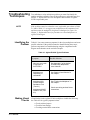
Troubleshooting Techniques
Identifying the Problem .
Making Visual Checks . .
Testing the Multiplexer .
.
.
.
.
.
.
.
.
.
.
.
.
.
.
.
.
.
.
.
.
.
.
.
.
.
.
.
.
.
.
.
.
.
.
.
.
.
.
.
.
.
.
.
.
.
.
.
.
.
.
.
.
.
.
.
.
.
.
.
.
.
.
.
.
.
.
.
.
.
.
.
.
.
.
.
.
.
.
.
.
.
.
.
.
.
.
.
.
.
.
.
.
.
.
.
.
.
.
.
.
.
.
.
.
.
.
.
.
.
.
.
.
.
.
.
.
.
.
.
.
.
.
.
.
.
.
.
.
.
.
.
.
...
...
...
...
.
.
.
.
.
.
.
.
.
.
.
.
.
.
.
.
.
.
.
.
.
.
.
.
. 4-4
. 4-4
. 4-4
. 4-5
Repair and Maintenance Guidelines . . .
ESD Precautions . . . . . . . . . . . .
Soldering Printed Circuit Boards . . .
Post-Repair SafetyChecks . . . . . . .
.
.
.
.
.
.
.
.
.
.
.
.
.
.
.
.
.
.
.
.
.
.
.
.
.
.
.
.
.
.
.
.
.
.
.
.
.
.
.
.
.
.
.
.
.
.
.
.
.
.
.
.
.
.
.
.
.
.
.
.
.
.
.
.
.
.
.
.
.
.
.
.
.
.
.
.
.
.
.
.
.
.
.
.
.
.
.
.
.
.
.
.
.
.
.
.
.
.
.
.
.
.
.
.
.
.
.
.
.
.
.
.
.
.
.
.
.
.
.
.
.
.
.
.
.
.
.
.
. 4-7
. 4-7
. 4-7
. 4-7
.
.
.
.
.
.
.
.
Component Locators and Schematic Diagrams . . . . . . . . . . . . . . . . . . . . . . . . . . . . . . . . 4-8
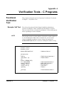
AppendixA - Verification Tests - C Programs
Functional Verificaiton Test . . . . . . . . . . . . . . . . . . . . . . . . . . . . . . . . . . . . . . . . . . . A-1
Example: Self Test . . . . . . . . . . . . . . . . . . . . . . . . . . . . . . . . . . . . . . . . . . . . . . A-1
Performance Verification Tests . . . . . . . . . . . . . . . . . . . . . . . . . . . . . . . . . . . . . . . . . A-2
Example: Closed Channel Resistance Test . . . . . . . . . . . . . . . . . . . . . . . . . . . . . . . . A-2
Example: DC Isolation Test . . . . . . . . . . . . . . . . . . . . . . . . . . . . . . . . . . . . . . . . A-6
vi
1
General Information
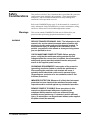
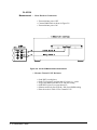
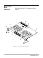
Introduction
This manual contains information required to test, troubleshoot, and repair
the Agilent E1346A Single Ended Relay Multiplexer. See the Agilent
E1346A User’s Manual for additional information on the Agilent E1346A.
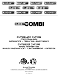
Figure 1-1 shows the Agilent E1346A Single Ended Relay Multiplexer.
Each multiplexer consists of a component assembly and a terminal block.
Figure 1-1. Agilent E1346A Single Ended Relay Multiplexer
1-1 General Information
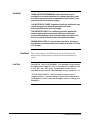
Safety
Considerations
This product is a Safety Class I instrument that is provided with a protective
earth terminal when installed in the mainframe. Check the mainframe,
multiplexer, and all related documentation for safety markings and
instructions before operation or service.
Refer to the WARNINGS page (page iii) in this manual for a summary of
safety information. Safety information for preventive maintenance, testing,
and service follows and is also found throughout this manual.
Warnings
WARNING
This section contains WARNINGS which must be followed for your
protection when performing equipment maintenance or repair.
SERVICE-TRAINED PERSONNEL ONLY. The information in this
manual is for service-trained personnel who are familiar with
electronic circuitry and are aware of the hazards involved. To
avoid personal injury or damage to the instrument, do not
perform procedures in this manual or do any servicing unless
you are qualified to do so.
CHECK MAINFRAME POWER SETTINGS. Before applying
power, verify that the mainframe setting matches the line
voltage and that the correct fuse is installed. An uninterruptible
safety earth ground must be provided from the main power
source to the supplied power cord set.
GROUNDING REQUIREMENTS. Interruption of the protective
(grounding) conductor (inside or outside the mainframe) or
disconnecting the protective earth terminal will cause a
potential shock hazard that could result in personal injury.
(Grounding one conductor of a two-conductor outlet is not
sufficient protection.)
IMPAIRED PROTECTION. Whenever it is likely that instrument
protection has been impaired, the mainframe must be made
inoperative and be secured against any unintended operation.
REMOVE POWER IF POSSIBLE. Some procedures in this
manual may be performed with power supplied to the
mainframe while protective covers are removed. Energy
available at many points may, if contacted, result in personal
injury. (If maintenance can be performed without power applied,
the power should be removed.)
1-2 General Information
WARNING
USING AUTOTRANSFORMERS. If the mainframe is to be
energized via an autotransformer (for voltage reduction) make
sure the common terminal is connected to neutral (that is, the
grounded side of the main’s supply).
CAPACITOR VOLTAGES. Capacitors inside the mainframe may
remain charged even when the mainframe has been
disconnected from its source of supply.
USE PROPER FUSES. For continued protection against fire
hazard, replace the line fuses only with fuses of the same
current rating and type (such as normal blow, time delay, etc.).
Do not use repaired fuses or short-circuited fuseholders.
WIRING INSULATION. To prevent electrical shock, all wires to
the channel connections must be insulated to at least 120 V rms
(170 V peak).
Cautions
CAUTION
This section contains CAUTIONS which must be followed to avoid
damage to the equipment when performing instrument maintenance or
repair.
MAXIMUM VOLTAGE/CURRENT. The maximum voltage that may
be applied between High (H), Low (L), and Guard (G) terminals is 120
V dc or 120 V rms (170 V peak). The maximum current is 50 mA
(non-inductive) per channel. The maximum power per channel is 1 VA.
STATIC ELECTRICITY. Static electricity is a major cause of
component failure. To prevent damage to the electrical components in
the multiplexers, observe anti-static techniques whenever working on a
multiplexer.
1-3 General Information
Relay Life
Loading and
Switching
Frequency Effects
Electromagnetic relays are subject to normal wear-out. Relay life depends
on several factors. Two factors are loading and switching frequency.
Relay Load. In general, higher power switching reduces relay life. In
addition, capacitive/inductive loads and high inrush currents (e.g., when
turning on a lamp or motor) reduce relay life. Exceeding the specified
maximum inputs can cause catastrophic failure.
Switching Frequency. Relay contacts heat up when switched. As the
switching frequency increases, the contacts have less time to dissipate heat.
The resulting increase in contact temperature reduces relay life.
End of Life
Detection
A preventive maintenance routine can prevent problems caused by
unexpected relay failure. The end of the life of a relay can be determined
using one or more of the following methods. The best method (or
combination of methods), as well as the failure criteria, depends on the
application in which the relay is used.
Check Contact Resistance. As a relay begins to wear out, its contact
resistance will increase. When the resistance exceeds a pre-determined
value, the relay should be replaced. Typically, a relay for the Agilent
E1346A Multiplexer should be replaced when the contact resistance exceeds
2.0 Ω.
Check Stability of Contact Resistance. The stability of relay contact
resistance decreases with age. Using this method, the contact resistance is
measured several times (5-10), and the variance of the measurements is
determined. An increase in the variance indicates deteriorating performance.
Replace Relays after Defined Number of Operations. Relays can be
replaced after a predetermined number of contact closures. However, this
method requires knowledge of the applied load and life specifications for
the applied load. For the Agilent E1346A Single Ended Relay Multiplexer,
maximum relay life is specified to be 108 operations at no load or 107
operations at rated load.
1-4 General Information
Replacement
Strategy
The replacement strategy also depends on the application. If some relays are
used more often, or at higher load, than the others, the relays can be
individually replaced as needed. If all of the relays see similar loads and
switching frequencies, the entire circuit board can be replaced when the end
of life approaches. The sensitivity of the application should be weighed
against the cost of replacing relays with some useful life remaining.
NOTE
Relays that wear out normally or fail due to misuse should not be
considered defective and are not covered by the product’s warranty.
1-5 General Information
Multiplexer
Description
NOTE
The Agilent E1346A Single Ended Relay Multiplexer is an "instrument" in
a VXIbus mainframe. As such, the multiplexer is assigned an error queue,
input and output buffers, and a status register.
Instruments are based on the logical addresses of the plug-in modules. See
the Agilent 75000 Series B Installation and Getting Started Guide to set the
addresses to create an instrument.
E1346A
Description
The Agilent E1346A Single Ended Relay Multiplexer provides switching
(multiplexing) of up to 48 channels (i.e., channels 00 to 47). Each channel
switches only a High (H) connection. The Low (L) and Guard (G)
connections are common for all channels. The multiplexer module can only
close one channel at a time.
Multiplexer
Specifications
See Appendix A of the Agilent E1346A User’s Manual for Agilent E1346A
specifications. These specifications are the performance standards or limits
against which the instrument may be tested.
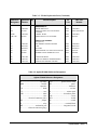
Multiplexer
Environment
The recommended operating environment for the Agilent E1346A Single
Ended Relay Multiplexer is:
Environment
1-6 General Information
Temperature
Humidity
Operating
0oC to +55oC
<65% relative (0oC to +40oC)
Storage and
Shipment
-40oC to +75oC
<65% relative (0oC to +40oC)
Multiplexer
Serial Numbers
Multiplexers covered by this manual are identified by a serial number prefix
listed on the title page. Agilent Technologies uses a two-part serial number
in the form XXXXAYYYYY, where XXXX is the serial prefix, A is the
country of origin (A=USA), and YYYYY is the serial suffix. The serial
number prefix identifies a series of identical instruments. The serial number
suffix is assigned sequentially to each instrument.
The serial number plate is located on the backplane connector. If the serial
number prefix of your instrument is greater than the one listed on the title
page, a Manual Update (as required) will explain how to adapt this manual
to your instrument.
Multiplexer
Options
Schematics/
Component
Locators
There are no electrical or mechanical options available for the Agilent
E1346A Single-Ended Relay Multiplexer.
Component locators and schematics for the multiplexers are packaged with
this manual. Clear plastic sleeves are included for storage.
1-7 General Information
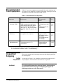
Recommended
Test Equipment
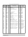
Table 1-1 lists the test equipment recommended for testing, adjusting, and
servicing the relay multiplexer. Essential requirements for each piece of test
equipment are described in the Requirements column.
Table 1-1. Recommended Test Equipment
Instrument
Requirements
Recommended
Model
Use*
Controller, GPIB
GPIB compatibility as defined by
IEEE Standard 488-1987 and the
identical ANSI Standard MC1.1:
SH1, AH1, T2, TE0, L2, LE0, SR0,
RL0, PP0, DC0, DT0, and C1, 2, 3,
4, 5.
HP 9000 Series 300
or
IBM Compatible PC
with BASIC
F,O,
P,T
Mainframe
Compatible with multiplexer
Agilent E1300B,
E1301B, E1302A or
E1401B/T,
E1421A/B (requires
E1405A/B)
F,O,
P,T
Digital Multimeter
2-wire ohms (up to 1 GΩ)
4-wire ohms
Agilent 3458A or
Agilent 34401A
O,P,T
* F = Functional Verification, O = Operation Verification Tests,
P = Performance Verification Tests, T = Troubleshooting
Inspection/
Shipping
Initial
Inspection
WARNING
1-8 General Information
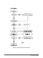
This section contains initial (incoming) inspection and shipping guidelines
for the multiplexer.
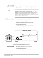
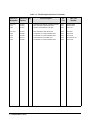
Use the steps in Figure 1-2 as guidelines to perform initial inspection of a
relay multiplexer. Performance Verification tests are optional.
To avoid possible hazardous electrical shock, do not perform
electrical tests if there are signs of shipping damage to the
shipping container or to the instrument.
Notify Agilent and carrier.
Notify Agilent
Return Multiplexer to Agilent
Figure 1-2. Initial (Incoming) Inspection Guidelines
1-9 General Information
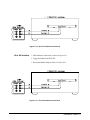
Shipping
Guidelines
Follow the steps in Figure 1-3 to return a relay multiplexer to a Agilent
Technologies Sales and Support Office or Service Center.
1 Prepare the Multiplexer
• Remove user wiring from terminal block
• Attach tag to module/pod that identifies
- Owner
- Model Number/Serial Number
- Service Required
• Place tagged device in approved anti-static bag
2 Package the Multiplexer
• Place packaged multiplexer in shipping carton*
• Place 75 to 100 mm (3 to 4 inches) of shockabsorbing material around the multiplexer.
• Seal the shipping carton securely.
• Mark the shipping carton FRAGILE.
3 Ship the Multiplexer to Agilent Technologies
• Place address label on shipping carton
• Send carton to Agilent Technologies
*We recommend that you use the same shipping materials as those used in factory packaging (available from
Agilent Technologies).
For other (commercially-available) shipping materials, use a double-wall carton with a minimum 2.4 MPa (350 psi) test.
Figure 1-3. Packaging/Shipping Guidelines
1-10 General Information
2
Verification Tests
Introduction
This chapter describes the verification tests for the Agilent E1346A Single
Ended Relay Multiplexer. The three levels of test procedures described in
this chapter are used to verify that the Agilent E1346A:
• is functional (Functional Verification Test)
• meets selected testable specifications (Operation Verification)
• meets all testable specifications (Performance Verification)
Test Conditions/
Procedures
See Table 1-1 for test equipment requirements. You should complete the
Performance Verification tests at least once a year. For heavy use or severe
operating environments, perform the tests more often. The verification tests
assume that the person performing the tests understands how to operate the
mainframe, the multiplexers, and the specified test equipment. The test
procedures do not specify equipment settings for test equipment except in
general terms. It is assumed that a qualified, service-trained technician will
select and connect the cables, adapters, and probes required for the test.
Performance
Test Record
The results of each Performance Verification test may be recorded in Table
2-2, Performance Test Record, at the end of this chapter. You can make a
copy of this form, if desired.
Verification Test
Examples
Each verification test procedure includes an example program that performs
the test. All example programs assume the following configuration:
•
•
•
•
•
HP 9000 Series 200/300 computer
BASIC programming language
Multiplexer address 70914
Multiplexer card number 1
Agilent 3458A Digital Multimeter (DMM)
Verification Tests 2-1
Functional
Verification
Test
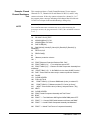
Procedure
The Functional Verification Test for the Agilent E1346A Single Ended
Relay Multiplexer consists of sending the *IDN? command and checking
the response. This test can be used to verify that the multiplexer is
connected properly and is responding to a basic command.
1. Verify that the multiplexer is properly installed in mainframe
2. Verify that the mainframe has passed its power-on test.
3. Send *IDN? to the multiplexer (see example following)
4. The return should be as follows (revision number may vary):
HEWLETT-PACKARD,SWITCHBOX,0,A.06.00
NOTE
Example
If the primary address setting, secondary address setting, or the interface
select code is set incorrectly, the multiplexer will not respond. Verify proper
address selection before troubleshooting.
An example follows which uses an HP 9000 Series 300 computer with
BASIC and a multiplexer address of 70914.
10 DIM A$[100]
20 OUTPUT 70914;"*IDN?"
30 ENTER 70914;A$
40
!Send the ID command
!Get response
PRINT A$
50 END
Operation
Verification
Test
The procedures in this section are used to provide a high level of confidence
that the multiplexer is meeting published specifications.
The Operation Verification test is a subset of the Performance Verification
tests and is suitable for checkout after performing repairs.
The Operation Verification Test is performed by completing the Closed
Channel Resistance Test (Test 2-1) as described in the Performance
Verification test procedures. This test is usually sufficient to verify that the
multiplexer is meeting its specifications.
2-2 Verification Tests
Performance
Verification
Tests
The procedures in this section are used to test the multiplexer’s electrical
performance using the specifications in Appendix A - Specifications of the
Agilent E1346A Single Ended Relay Multiplexer User’s Manual as the
performance standard.
There are two performance verification tests for the relay multiplexers: Test
2-1: Closed-Channel Resistance Test and Test 2-2: DC Isolation Test.
These tests are suitable for incoming inspection, troubleshooting, and
preventive maintenance.
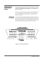
Wiring the
Test Fixture
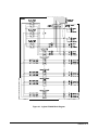
A test fixture is required for the performance verification tests. Figure 2-1
shows typical connections using an Agilent E1346A terminal block for the
test fixture. You may want to order an extra terminal block to use as a test
fixture, so that you don’t have to re-wire each time the tests are performed.
The Agilent E1346A terminal block part number is E1346-80001.
Figure 2-1. Test Fixture Connections
Verification Tests 2-3
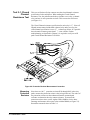
Test 2-1: Closed
Channel
Resistance Test
This test verifies that all relay contacts meet the closed-channel resistance
specification for the multiplexer. When making the Closed Channel
Resistance Test, the path measured always includes: a tree relay, a channel
relay, and one or more protection resistors. This test uses the test fixture
(see Figure 2-1).
The Closed Channel resistance specification for each relay is 2 Ω. Since all
HI path measurements include both a channel relay and a tree relay, the
closed channel specification is set to 2 Ω to detect any failure. It is possible
that a channel resistance greater than 2 Ω is not a failure. Further
troubleshooting, as described in Chapter 4, is required to verify a true HI
path Closed Channel Resistance Test failure.
Figure 2-2. Protection Resistor Measurement Connection
Measuring
Protection
Resistors
2-4 Verification Tests
Since there are 100 Ω protection resistors (R38 through R43) in the relay
paths, measure the protection resistor values to begin this test. The values of
the protection resistors are then subtracted from the measured path
resistance to determine the relay contact resistance. To measure the
protection resistor values, set the Agilent 3458A DMM to 4-wire ohms,
autorange and measure each resistor value with the DMM (see Figure 2-2).
Record the measured values in Table 2-1.
Table 2-1. Measured Protection Resistor Values
Resistor
Measured Value (Ω)
R38
R39
R40
________________
________________
________________
Chs 00-47 and 90-92
HI Measurements
Resistor
R41
R42
R43
Measured Value (Ω)
________________
________________
________________
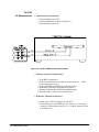
1 . Make Hardware Connections
• Turn mainframe power OFF
• Connect DMM leads as shown in Figure 2-3
• Turn mainframe power ON
Figure 2-3. Ch 00-47 HI Measurement Connections
2. Measure Channel 00 HI Resistance
•
•
•
•
•
•
Send *RST to multiplexer
Send CLOS (@nn00) to close chan 00, where nn = card #
Trigger the DMM with TRIG SGL and note reading
Send OPEN (@nn00) to open channel 00
Subtract measured value of R43 from DMM reading
Enter the result in Table 2-2 for Channel 00 HI
3. Repeat for Channels 01 - 47 HI
• Repeat step 2 for channels 01 - 47 HI
• Use CLOS (@nncc) and OPEN (@nncc), where nn =
card # and cc = channel # (omit leading zeroes in nn)
Verification Tests 2-5
Ch 90-92
LO Measurements
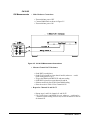
1 . Make Hardware Connections
• Turn mainframe power OFF
• Connect DMM leads as shown in Figure 2-4
• Turn mainframe power ON
Figure 2-4. Ch 90 LO Measurement Connections
1. Measure Channel 90 LO Resistance
• Send *RST to multiplexer
• Send CLOS (@nn00) to close chan 90 and 00, where nn = card #
•
•
•
•
(omit leading zeroes in nn ).
Trigger the DMM with TRIG SGL and note reading
Send OPEN (@nn00) to open channel 90 and 00
Subtract measured value of R42 from DMM reading
Enter the result in Table 2-2 for Channel 90 LO
2. Repeat for Channels 91 and 92 LO
• Repeat steps 1 and 2 for channels 91 and 92 LO
• Use CLOS (@nncc) and OPEN (@nncc), where nn = card # and cc
= channel # (omit leading zeroes in nn ). Use 08 for channel 91 and
16 for channel 92.
2-6 Verification Tests
Ch 90-92
GU Measurements
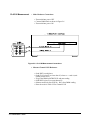
1. Make Hardware Connections
• Turn mainframe power OFF
• Connect DMM leads as shown in Figure 2-5
• Turn mainframe power ON
Figure 2-5. Ch 90 GU Measurement Connections
2. Measure Channel 90 GU Resistance
• Send *RST to multiplexer
• Send CLOS (@nn00) to close chan 90 and 00, where nn = card #
•
•
•
•
(omit leading zeroes in nn ).
Trigger the DMM with TRIG SGL and note reading
Send OPEN (@nn00) to open channel 90 and 00
Subtract measured value of R41 from DMM reading
Enter the result in Table 2-2 for Channel 90 GU
3. Repeat for Channels 91 and 92 GU
• Repeat steps 1 and 2 for channels 91 and 92 GU
• Use CLOS (@nncc) and OPEN (@nncc), where nn = card # and cc
= channel # (omit leading zeroes in nn) Use 08 for channel 91 and 16
for channel 92.
Verification Tests 2-7
Ch 93 HI Measurement
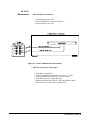
1. Make Hardware Connections
• Turn mainframe power OFF
• Connect DMM leads as shown in Figure 2-6
• Turn mainframe power ON
Figure 2-6. Ch 93 HI Measurement Connections
2. Measure Channel 93 HI Resistance
• Send *RST to multiplexer
• Send CLOS (@nn93) to close chan 93, where nn = card # (omit
•
•
•
•
2-8 Verification Tests
leading zeroes in nn )
Trigger the DMM with TRIG SGL and note reading
Send OPEN (@nn93) to open channel 93
Subtract measured value of (R38 + R43) from DMM reading
Enter the result in Table 2-2 for Channel 93 HI
Ch 93 LO
Measurement
1. Make Hardware Connections
• Turn mainframe power OFF
• Connect DMM leads as shown in Figure 2-7
• Turn mainframe power ON
Figure 2-7. Ch 93 LO Measurement Connections
2. Measure Channel 93 LO Resistance
•
•
•
•
•
•
Send *RST to multiplexer
Send CLOS (@nn93) to close chan 93, where nn = card #
Trigger the DMM with TRIG SGL and note reading
Send OPEN (@nn93) to open channel 93
Subtract measured value of (R39 + R42) from DMM reading
Enter the result in Table 2-2 for Channel 93 LO
Verification Tests 2-9
Ch 93 GU
Measurement 1. Make Hardware Connections
• Turn mainframe power OFF
• Connect DMM leads as shown in Figure 2-8
• Turn mainframe power ON
Figure 2-8. Ch 93 GU Measurement Connections
2. Measure Channel 93 GU Resistance
•
•
•
•
•
•
2-10 Verification Tests
Send *RST to multiplexer
Send CLOS (@nn93) to close chan 93, where nn = card #
Trigger the DMM with TRIG SGL and note reading
Send OPEN (@nn93) to open channel 93
Subtract measured value of (R40 + R41) from DMM reading
Enter the result in Table 2-2 for Channel 93 GU
Example: Closed
Channel Resistance
Test
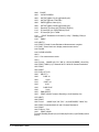
NOTE
This example performs a Closed Channel Resistance Test to measure
Channels 00 - 47, Channels 90-92 and Channel 93 HI, LO, and GU relay
contact resistances. If the relay contact resistance for a channel is >2.0 Ω
the program prints a message indicating which channel has failed the test.
Use this list in chapter 4 when troubleshooting a failing relay.
Since small measurement variations may occur when measuring the
protection resistors, the program returns "0.00" if the calculated resistance
is <0 Ω .
10! RE-SAVE "CLOS_TEST"
20
ASSIGN @Dmm TO 722
30
ASSIGN @Mux TO 70914
40
DISP CHR$(129)
50
DIM R(38:43),Value0(47),Value1(3,3),Result0(47),Result1(3,3),
Path$(2)[2]
60
DATA HI,LO,G
70
READ Path$(*)
80
!
90
!Measure protection resistors
100 !
110 PRINT "Measure Protection Resistors R38 - R43 "
120 PRINT TABXY(1,3)," 1. Turn mainframe power OFF"
130 PRINT TABXY(1,4)," 2. Remove E1346A Component Assembly from
mainframe"
140 PRINT TABXY(1,5)," 3. Set DMM for 4-wire ohms (OHMF) function "
150 DISP " Press Continue when ready to measure protection resistors "
160 PAUSE
170 CLEAR SCREEN
180 FOR I=38 TO 43
190
PRINT TABXY(1,4),"Connect DMM leads (4-wire) to resistor R";I
200
PRINT TABXY(1,5),"Measure resistor R";I;"value (in Ohms)"
210
INPUT " Enter resistor value (in Ohms), and press Return ",R(I)
220 NEXT I
230 CLEAR SCREEN
240 PRINT "Install Component Assembly and Test Fixture "
250 PRINT
260 PRINT " 1. Turn Mainframe AND Agilent 3458a DMM power OFF"
270 PRINT " 2. Connect GPIB Cable between mainframe and DMM"
280 PRINT " 3. Install E1346A Component Assembly into Mainframe"
290
PRINT " 4. Attach Test Fixture to Component Assembly"
Verification Tests 2-11
300
310
320
330
340
350
360
PRINT " 5. Turn Mainframe power ON "
PRINT " 5. Press Continue when ready to begin testing "
PAUSE
CLEAR SCREEN
!
! Measure Channels 00-47 and 90-92 (HI, LO, and G)
!
370 OUTPUT @Dmm;"PRESET NORM;FUNC OHMF"
380 OUTPUT @Mux;"*RST"
390 J=100 ! Address offset
400 K=0
410 PRINT TABXY(1,1),"Channel 00-47 and 90-92";Path$(K);"
Measurements"
420 PRINT TABXY(1,3),"Connect DMM Sense and Input HI leads to
COMMON ";Path$(K)
430 PRINT TABXY(1,4),"Connect DMM Sense and Input LO leads to
VOLTAGE SENSE ";Path$(K)
440 DISP " Press Continue when connections are complete "
450 PAUSE
460 CLEAR SCREEN
470 FOR I=0 TO 47
480
OUTPUT @Mux;"CLOS (@"&VAL$(J+I)&")"
490
OUTPUT @Dmm;"TRIG SGL"
500
ENTER @Dmm;Value0(I)
510
OUTPUT @Mux;"OPEN (@"&VAL$(J+I)&")"
520
Result0(I)=Value0(I)-R(43)
530
IF Result0(I)<0. THEN Result0(I)=0
540
IF Result0(I)>2.0 THEN
550
PRINT "Resistance for Channel";I;" ";Path$(K);"Path is >2.0
Ohms"
560
END IF
570 NEXT I
580 PRINT "Measurements complete for Channels 00 - 47 and 90-92
";Path$(K)
590 DISP " Press Continue for Channels 90 - 92 ";Path$(K+1);"
measurements "
600 PAUSE
610 !
620 ! Measure channels 90-92 LO and G
630 !
640 OUTPUT @Mux;"*RST"
650 FOR K=1 TO 2
660
CLEAR SCREEN
2-12 Verification Tests
670
PRINT TABXY(1,1),"Channels 90-92 ";Path$(K);"
Measurements"
680
PRINT TABXY(1,3),"Connect DMM Sense and Input HI leads to
COMMON ";Path$(K)
690
PRINT TABXY(1,4),"Connect DMM Sense and Input LO leads to
VOLTAGE SENSE ";Path$(K)
700
DISP " Press Continue when connections are complete "
710
PAUSE
720
CLEAR SCREEN
730
J=100 ! Address Offset
740
FOR I=0 TO 2
750
OUTPUT @Mux;"CLOS (@"&VAL$(J)&")"
760
OUTPUT @Dmm;"TRIG SGL"
770
ENTER @Dmm;Value1(I,K)
780
OUTPUT @Mux;"OPEN (@"&VAL$(J)&")"
790
Result1(I,K)=Value1(I,K)-R(43-K)
800
IF Result1(I,K)<0. THEN Result1(I,K)=0.
810
IF Result1(I,K)>2.0 THEN
820
PRINT "Resistance for Channel ";(I+90);" ";Path$(K);"Relay is
>2.0 Ohms"
830
END IF
840
J=J+8
850
NEXT I
860
PRINT "Measurements complete for Channels 90-92";Path$(K)
870 IF K=1 THEN
880
DISP " Press Continue for Channels 90 - 92 ";Path$(K+1);"
measurements "
890
PAUSE
900
END IF
910 NEXT K
920 !
930 ! Measure channel 93 HI, LO, and G
940 !
950 DISP " Press Continue for Channel 93 HI, LO, and G measurements "
960 PAUSE
970 CLEAR SCREEN
980 J=193 ! Address offset
990 FOR K=0 TO 2
1000 PRINT TABXY(1,1),"Channel 93 HI, LO, and G Contact Resistance
Test"
1010 PRINT TABXY(1,3),"1. Connect DMM Sense and Input HI leads to
VOLTAGE SENSE ";Path$(K)
1020 PRINT TABXY(1,4),"2. Connect DMM Sense and Input LO leads to
CURRENT SOURCE ";Path$(K)
1030 DISP " Press Continue when connections are complete "
Verification Tests 2-13
1040
1050
1060
1070
1080
1090
1100
PAUSE
CLEAR SCREEN
OUTPUT @Mux;"CLOS (@"&VAL$(J)&")"
OUTPUT @Dmm;"TRIG SGL"
ENTER @Dmm;Value1(K,3)
OUTPUT @Mux;"OPEN (@"&VAL$(J)&")"
Result1(K,3)=Value1(K,3)-(R(38+K)+R(43-K))
1110
IF Result1(K,3)<0 THEN Result1(K,3)=0.
1120
IF Result1(K,3)>2.0 THEN
1130
PRINT "Resistance for Channel";(J-100);" ";Path$(K);"Relay is
>2.0 Ohms"
1140
END IF
1150 NEXT K
1160 PRINT "Closed Contact Resistance Measurements complete
1170 DISP " Press Continue to display measurement results "
1180 PAUSE
1190 CLEAR SCREEN
1200 !
1210 ! Print measurement results
1220 !
1230 Format: IMAGE 2(5X,"CH ",DD," & ",DD,3X,DD.DDDD," Ohms",5X)
1240 PRINT TABXY(1,3),"Channels 00-47 & 90-92 HI Contact Resistance"
1250 PRINT
1260 PRINT
1270 FOR I=0 TO 23
1280
SELECT I
1290
CASE <8
1300
K=90
1310
CASE <16
1320
K=91
1330
CASE ELSE
1340
K=92
1350
END SELECT
1360
PRINT USING Format;I,K,Result0(I),I+24,K,Result0(I+24)
1370 NEXT I
1380 PRINT
1390 Form2:
IMAGE 3(2X,"CH ",DD," ",2A,2X,DD.DDDD," Ohms",2X)
1400 PRINT "Channels 90-92 LO and G Contact Resistance"
1410 PRINT
1420 FOR K=1 TO 2
1430
PRINT USING
Form2;90,Path$(K),Result1(0,K),91,Path$(K),Result1(1,K),92,Path$(K),Resu
lt1(2,K)
2-14 Verification Tests
1440
1450
1460
1470
1480
1490
1500
NEXT K
PRINT
PRINT "Channel 93 Contact Resistance"
PRINT
FOR K=0 TO 2
PRINT "Channel 93 ";Path$(K);" ";Result1(K,3);" Ohms"
NEXT K
1510 END
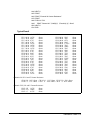
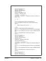
Typical Result
Channel 00-47 and Channels 90-92 HI Contact Resistance
CH 0 & 90
CH 1 & 90
CH 2 & 90
CH 3 & 90
CH 4 & 90
CH 5 & 90
CH 6 & 90
CH 7 & 90
CH 8 & 91
CH 9 & 91
CH 10 & 91
CH 11 & 91
CH 12 & 91
CH 13 & 91
CH 14 & 91
CH 15 & 91
CH 16 & 92
CH 17 & 92
CH 18 & 92
CH 19 & 92
CH 20 & 92
CH 21 & 92
CH 22 & 92
CH 23 & 92
1.6785
.6885
.6725
.6785
1.6785
1.4785
1.5785
1.6785
.6785
.6785
.8685
1.256
.8555
.6785
.7865
.6785
.6785
1.6785
1.6785
.6785
.6780
.4485
.6785
1.6785
Ohms
Ohms
Ohms
Ohms
Ohms
Ohms
Ohms
Ohms
Ohms
Ohms
Ohms
Ohms
Ohms
Ohms
Ohms
Ohms
Ohms
Ohms
Ohms
Ohms
Ohms
Ohms
Ohms
Ohms
CH 24 & 90
CH 25 & 90
CH 26 & 90
CH 27 & 90
CH 28 & 90
CH 29 & 90
CH 30 & 90
CH 31 & 90
CH 32 & 91
CH 33 & 91
CH 34 & 91
CH 35 & 91
CH 36 & 91
CH 37 & 91
CH 38 & 91
CH 39 & 91
CH 40 & 92
CH 41 & 92
CH 42 & 92
CH 43 & 92
CH 44 & 92
CH 45 & 92
CH 46 & 92
CH 47 & 92
.5995
.7865
.6578
1.865
1.72225
.7865
.59005
.7865
.4566
.7865
.7222
.9885
.7865
1.2265
.9995
.7555
.5996
.7865
.9595
.5566
.9865
.7865
.6785
.7865
Ohms
Ohms
Ohms
Ohms
Ohms
Ohms
Ohms
Ohms
Ohms
Ohms
Ohms
Ohms
Ohms
Ohms
Ohms
Ohms
Ohms
Ohms
Ohms
Ohms
Ohms
Ohms
Ohms
Ohms
Channels 90-92 LO and G Contact Resistance
.
.
CH 90 LO .1023 Ohms CH 91 LO .1125 Ohms CH 92 LO .2011 Ohms
CH 90 G .1113 Ohms CH 91 G .1985 Ohms CH 92 G .0955 Ohms
Channel 93 HI, LO and G Contact Resistance
CH 93 HI 1.6785
CH 93 LO 1.0005
CH 93 G 0.1785
Ohms
Ohms
Ohms
Verification Tests 2-15
Test 2-2: DC
Isolation Test
NOTE
This test verifies that sufficient DC isolation exists at various points on the
multiplexer. DC Isolation is checked from HI to Chassis, HI to LO, and HI
to GU (GUARD). This test uses the test fixture (see Figure 2-1).
The DMM used should be capable of measuring at least 1 G. Ω. If the
DMM indicates an overload, record the reading as >Rmax, where Rmax is
the highest resistance that the DMM can measure. For example, if the
DMM is an Agilent 3458A, a typical return for an overload is 1.E+38 and
the entry in Table 2-2 should be >1.2 G Ω.
HI to Chassis Isolation
1. Make hardware connections as shown in Figure 2-9
2. Set DMM to 2-wire ohms, 1 G Ω range
3. Send CLOS (@100,108,116,193) to close all Tree relays
4. Trigger the DMM with TRIG SGL
5. Record the DMM reading on Table 2-2 (HI to CHASSIS)
Figure 2-9. HI to Chassis Isolation Connections
HI to LO Isolation
1. Make hardware connections as shown in Figure 2-10
2. Trigger the DMM with TRIG SGL
3. Record the DMM reading on Table 2-2 (HI to LO)
2-16 Verification Tests
Figure 2-10. HI to LO Isolation Connections
HI to GU Isolation
1. Make hardware connections as shown in Figure 2-11
2. Trigger the DMM with TRIG SGL
3. Record the DMM reading on Table 2-2 (HI to GU)
Figure 2-11. HI to GU Isolation Connections
Verification Tests 2-17
Example:
DC Isolation Test
This example performs DC Isolation Tests for HI to Chassis, HI to LO, and
HI to GU (GUARD).
10! RE-SAVE "DC_ISOL"
20 ASSIGN @Dmm TO 722
30 ASSIGN @Mux TO 70914
40 DISP CHR$(129)
50 DIM Conn$(5)[10]
60 DATA CHASSIS, LO, G , CHASSIS, COMMON LO, COMMON G
70 READ Conn$(*)
80 OUTPUT @Dmm;"OHM 1E9"
90 PRINT "Equipment Connections "
100 PRINT
110 PRINT " 1. Turn Mainframe and Agilent 3458A DMM power OFF"
120 PRINT " 2. Connect GPIB Cable between mainfrmae and DMM"
130 PRINT " 3. Install Agilent E1346A Component Assembly into
Mainframe "
140 PRINT " 4. Attach Test Fixture to Component Assembly"
150 PRINT " 5. Turn Mainframe power ON"
160 DISP "Press Continue when ready to begin testing "
170 PAUSE
180 CLEAR SCREEN
190 !
200 ! Measure DC Isolation (HI to Chassis, HI to LO, HI to G)
210 !
220 OUTPUT @Mux;"*RST"
230 OUTPUT @Mux;"CLOS (@193,100,108,116)
240 FOR I=0 TO 2
250 PRINT TABXY(1,1),"DC Isolation HI to ";Conn$(I);" Measurements "
260 PRINT TABXY(1,3),"1. Connect DMM INPUT HI lead to COMMON
HI"
270 PRINT TABXY(1,4),"2. Connect DMM INPUT LO to ";Conn$(I+3)
280 DISP " Press Continue when connections are complete "
290 PAUSE
300 CLEAR SCREEN
310 OUTPUT @Dmm;"TRIG SGL"
320 ENTER @Dmm;Value(I)
330 NEXT I
340 OUTPUT @Mux;"OPEN (@193,100,108,116)
350 DISP " Press Continue to print measurement results "
2-18 Verification Tests
360
370
380
390
400
410
420
Typical Result
PAUSE
CLEAR SCREEN
PRINT TABXY(1,1),"DC Isolation Tests "
PRINT TABXY(1,3),"HI to CHASSIS (Ohms)";Value(0)
PRINT TABXY(1,4),"HI to LO (Ohms)
";Value(1)
PRINT TABXY(1,5),"HI to GUARD (Ohms) ";Value(2)
END
A typical result for an overload on all three measurements is :
DC Isolation Tests
HI to CHASSIS (Ohms) 1.E+38
HI to LO (Ohms)
1.E+38
HI to GUARD (Ohms) 1.E+38
Verification Tests 2-19
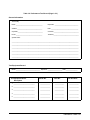
Performance
Test Record
Table 2-2, Performance Test Record, is a form you can copy and use to
record performance verification test results for the multiplexers. Table 2-2
shows multiplexer test limits, DMM measurement uncertainty, and test
accuracy ratio (TAR) values.
Test Limits
Test limits are defined for relay closed channel resistance and DC isolation
using the specifications in Appendix A - Specifications of the Agilent
E1346A Single Ended Relay Multiplexers User’s Manual . The relay contact
resistance and DC isolation specifications are single-ended, meaning that
there is an upper limit OR a lower limit, but not both. In Table 2-2, the
Minimum or Maximum column is blank for a single-sided test.
Measurement
Uncertainty
For the performance verification tests in this manual, measurement
uncertainties are calculated based on the Agilent 3458A Digital Multimeter.
The measurement uncertainty shown in Table 2-2 is the accuracy of the
Agilent 3458A using 90-day specifications. The calculations follow.
Closed Channel
Resistance Test
Conditions:
• 4-wire ohms function, 10 Ω range
• 90-day specifications
• Worst-case reading = 2.0 Ω
M.U. = (15 ppm of Reading + 5 ppm of Range)
= (15x10-6 * 2.0 + 5x10-6 * 10) Ω
= 8.0x10⁻⁵ Ω
DC Isolation Test
Conditions:
• 2-wire ohms function, 1 GΩ range
• 90-day specifications
• Worst-case reading = 1.2 GΩ (highest resistance that can be
measured with the Agilent 3458A)
M.U. = (0.5% of Reading + 10ppm of Range)
= (0.005 * 1.2x109 + 10x10-6 * 1x109) Ω
= 6.0x10⁶ Ω
Test Accuracy
Ratio (TAR)
2-20 Verification Tests
Test Accuracy Ratios (TAR) are not defined for single-sided measurements,
so all closed-channel resistance and DC isolation measurements show NA
(Not Applicable) in the TAR column.
Table 2-2. Performance Test Record (Page 1 of 3)
General Information
Test Facility:
Name ____________________________________
Report No. ________________________________
Address __________________________________
Date _____________________________________
City/State __________________________________
Customer __________________________________
Phone ____________________________________
Tested by __________________________________
Special Notes:
___________________________________________________________________________________________
___________________________________________________________________________________________
___________________________________________________________________________________________
___________________________________________________________________________________________
___________________________________________________________________________________________
___________________________________________________________________________________________
Test Equipment Record
Model _________________________________ Report No. ____________________ Date ________________
Test Equipment Used:
Description
Model No.
Trace No.
Cal Due Date
1. _____________________________
_____________
_____________
_____________
2. _____________________________
_____________
_____________
_____________
3. _____________________________
_____________
_____________
_____________
4. _____________________________
_____________
_____________
_____________
5. _____________________________
_____________
_____________
_____________
Verification Tests 2-21
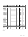
Table 2-2. Performance Test Record (Page 2 of 3)
Test No/Description
Minimum*
Value
Measured Value (V)
Maximum
Value **
Meas
Uncert
Test Acc
Ratio (TAR)
2-1. Closed Channel Resistance (Values in Ohms)
HI Path Resistance
Channel 00 & 90
Channel 01 & 90
Channel 02 & 90
Channel 03 & 90
Channel 04 & 90
Channel 05 & 90
Channel 06 & 90
Channel 07 & 90
___________________
___________________
___________________
___________________
___________________
___________________
___________________
___________________
2.0
2.0
2.0
2.0
2.0
2.0
2.0
2.0
8.00E-5
8.00E-5
8.00E-5
8.00E-5
8.00E-5
8.00E-5
8.00E-5
8.00E-5
NA
NA
NA
NA
NA
NA
NA
NA
Channel 08 & 91
Channel 09 & 91
Channel 10 & 91
Channel 11 & 91
Channel 12 & 91
Channel 13 & 91
Channel 14 & 91
Channel 15 & 91
___________________
___________________
___________________
___________________
___________________
___________________
___________________
___________________
2.0
2.0
2.0
2.0
2.0
2.0
2.0
2.0
8.00E-5
8.00E-5
8.00E-5
8.00E-5
8.00E-5
8.00E-5
8.00E-5
8.00E-5
NA
NA
NA
NA
NA
NA
NA
NA
Channel 16 & 92
Channel 17 & 92
Channel 18 & 92
Channel 19 & 92
Channel 20 & 92
Channel 21 & 92
Channel 22 & 92
Channel 23 & 92
___________________
___________________
___________________
___________________
___________________
___________________
___________________
___________________
2.0
2.0
2.0
2.0
2.0
2.0
2.0
2.0
8.00E-5
8.00E-5
8.00E-5
8.00E-5
8.00E-5
8.00E-5
8.00E-5
8.00E-5
NA
NA
NA
NA
NA
NA
NA
NA
Channel 24 & 90
Channel 25 & 90
Channel 26 & 90
Channel 27 & 90
Channel 28 & 90
Channel 29 & 90
Channel 30 & 90
Channel 31 & 90
___________________
___________________
___________________
___________________
___________________
___________________
___________________
___________________
2.0
2.0
2.0
2.0
2.0
2.0
2.0
2.0
8.00E-5
8.00E-5
8.00E-5
8.00E-5
8.00E-5
8.00E-5
8.00E-5
8.00E-5
NA
NA
NA
NA
NA
NA
NA
NA
Channel 32 & 91
Channel 33 & 91
Channel 34 & 91
Channel 35 & 91
___________________
___________________
___________________
___________________
2.0
2.0
2.0
2.0
8.00E-5
8.00E-5
8.00E-5
8.00E-5
NA
NA
NA
NA
*Single-sided specification - Minimum value does not apply
**Value listed is for a single relay contact. All channels measured include two relay contacts. Refer to Chapter 4 for troubleshooting
information.
2-22 Verification Tests
Table 2-2. Performance Test Record (Page 3 of 3)
Test No/Description
Minimum*
Value
Measured Value (V)
Maximum
Value **
Meas
Uncert
Test Acc
Ratio (TAR)
2-1. Closed Channel Resistance (Values in Ohms) (cont’d)
HI Path
Resistance
Channel 36 & 91
Channel 37 & 91
Channel 38 & 91
Channel 39 & 91
___________________
___________________
___________________
___________________
___________________
2.0
2.0
2.0
2.0
8.00E-5
8.00E-5
8.00E-5
8.00E-5
NA
NA
NA
NA
Channel 40 & 92
Channel 41 & 92
Channel 42 & 92
Channel 43 & 92
Channel 44 & 92
Channel 45 & 92
Channel 46 & 92
Channel 47 & 92
___________________
___________________
___________________
___________________
___________________
___________________
___________________
___________________
2.0
2.0
2.0
2.0
2.0
2.0
2.0
2.0
8.00E-5
8.00E-5
8.00E-5
8.00E-5
8.00E-5
8.00E-5
8.00E-5
8.00E-5
NA
NA
NA
NA
NA
NA
NA
NA
____________________
____________________
____________________
2.0
2.0
2.0
8.00E-5
8.00E-5
8.00E-5
NA
NA
NA
____________________
____________________
____________________
2.0
2.0
2.0
8.00E-5
8.00E-5
8.00E-5
NA
NA
NA
____________________
____________________
____________________
2.0
2.0
2.0
8.00E-5
8.00E-5
8.00E-5
NA
NA
NA
6.0E6
6.0E6
6.0E6
NA
NA
NA
LO Path
Resistance
Channel 90
Channel 91
Channel 92
G Path Resistance
Channel 90
Channel 91
Channel 92
Channel 93 Path
Resistance
Channel 93 HI
Channel 93 LO
Channel 93 G
2-2. DC Isolation (Values in Ohms) ***
HI to CHASSIS
HI to LO
HI to G
1E9
1E9
1E9
___________________
___________________
___________________
*Single-sided specification - Minimum value does not apply.
**Value listed is for a single relay contact. All channels measured include two relay contacts. Refer to Chapter 4 for troubleshooting
information.
***Single-sided specification - Maximum value does not apply.
Verification Tests 2-23
2-24 Verification Tests
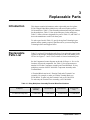
3
Replaceable Parts
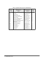
Introduction
This chapter contains information to order replaceable parts for Agilent
E1346A Single Ended Relay Multiplexers with serial number prefixes
2934A and below. Table 3-1 lists assembly and terminal block part numbers
for the multiplexer, Table 3-2 lists replaceable parts for the multiplexer,
Table 3-3 shows reference designators for parts in Table 3-2, and Table 3-4
shows the manufacturer code list for these parts.
To order a part listed in Table 3-2, specify the Agilent Technologies part
number and the quantity required. Send the order to your nearest Agilent
Technologies Sales and Support Office.
Replaceable
Parts List
Table 3-2, Agilent E1346A Replaceable Parts, lists replaceable parts for the
Agilent E1346A Single Ended Relay Multiplexer with serial number prefix
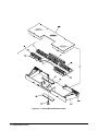
2934A. See Figures 3-1 and 3-2 for locations of selected mechanical parts.
See the Component Locator diagrams at the end of Chapter 4 - Service for
locations of electrical components. See Table 3-1 for replacement part
number for E1346A Component Assembly and Terminal Block. A relay
multiplexer consists of the E1346-66201 Component Assembly and a
Terminal Block.
A Terminal Block consists of a Terminal Card and a Terminal Case
Assembly. For example, to order an E1346A Terminal Block, use
E1346-80001. To order only the Terminal Card, use E1346-66510.
To order only the Terminal Case Assembly, use E1300-84401.
Table 3-1. Relay Multiplexer Assembly/Terminal Block Part Numbers
Multiplexer
E1346A SE Relay Mux
Component
Assembly
E1346-66201
Terminal Block
E1346-80001
Terminal Card
E1346-66510
Terminal Case
Assy
E1300-84401
Replaceable Parts 3-1
Table 3-2. Agilent E1346A Replaceable Parts
Reference Agilent Part Qty
Designator
Number
Part Description
Mfr.
Code
Mfr. Part
Number
ASSEMBLIES/CABLES/MANUALS
(See Figure 3-1)
A1
E1346-66201
1
MOD RLY MUXR 48CH SE
28480
E1346-66201
E1400-61605
1
CABLE RIBBON ASSEMBLY FOR E1400A
28480
E1400-61605
0050-2183
2
CASTING-ZINC P.C. BOARD HOLDER
28480
0050-2183
9220-4727
1
PAD
28480
9220-4727
9220-4728
1
PAD
28480
9220-4728
LBL1
E1300-84308
1
LBL LOGO AGILENT B SIZE
28480
E1300-84308
LBL2
E1300-84309
1
LBL LOGO VXI B SIZE
28480
E1300-84309
MNL1
E1346-90004
1
USER’S MANUAL
28480
E1346-90004
MP1-MP2
1400-1546
2
BRACKET PC BOARD HOLDER; BLACK;
EXTRUDED
28480
1400-1546
PNL1
E1346-00202
1
PNL-RR RLY MUXR
28480
E1346-00202
SCR1-SCR2
0515-0444
2
SCREW-MACHINE M2.5 X 0.45 8MM-LG PAN-HD
28480
0515-0444
0515-1968
BRK1-BRK2
SCR3-SCR4
0515-1968
2
SCREW PHM 2.5 X 11
28480
SHD1
E1300-80601
1
SHIELD SAFETY
28480
E1300-80601
W1
E1300-61605
1
CABLE ASSEMBLY, B-Size
28480
E1300-61605
A1
E1346-66501
1
PRINTED CIRCUIT ASSEMBLY 48 CHANNEL
RELAY
28480
E1346-66501
A1C1
0180-1746
2
CAPACITOR-FXD 15uF +-10% 20 V TA
56289
150D156X9020B2-DYS
A1C2-C3
0160-4822
3
CAPACITOR-FXD 1000pF +-5% 100 V CER C0G
04222
SA201A102JAAH
A1C5
0160-4801
4
CAPACITOR-FXD 100pF +-5% 100 V CER C0G
04222
SA102A101JAAH
COMPONENT ASSEMBLY
A1C6
0160-4822
CAPACITOR-FXD 1000pF +-5% 100 V CER C0G
04222
SA201A102JAAH
A1C7-C9
0160-4801
CAPACITOR-FXD 100pF +-5% 100 V CER C0G
04222
SA102A101JAAH
A1C11
0160-3334
1
CAPACITOR-FXD 0.01uF +-10% 50 V CER X7R
04222
SA105C103KAAH
A1C17
0160-4835
9
CAPACITOR-FXD 0.1uF +-10% 50 V CER X7R
04222
SA105C104KAAH
A1C38-C42
0160-4835
CAPACITOR-FXD 0.1uF +-10% 50 V CER X7R
04222
SA105C104KAAH
A1C44
0180-1746
CAPACITOR-FXD 15uF +-10% 20 V TA
56289
150D156X9020B2-DYS
A1C45-C46
0160-4835
CAPACITOR-FXD 0.1uF +-10% 50 V CER X7R
04222
SA105C104KAAH
A1C48
0160-4835
CAPACITOR-FXD 0.1uF +-10% 50 V CER X7R
04222
SA105C104KAAH
A1CR1
1902-0554
DIODE-ZENER 10V 5% PD=1W IR=10UA
04713
1N4740ARL
3-2 Replaceable Parts
1
Table 3-2. E1346A Replaceable Parts (Continued)
Reference Agilent Part Qty
Designator
Number
Part Description
Mfr.
Code
Mfr. Part
Number
A1CR2
8150-4086
1
WIRE 22AWG-WHITE TEFLON 1X22 105C
28480
8150-4086
A1F1
2110-0712
1
FUSE-SUBMINIATURE 4A 125V NTD AX
75915
R251004T1
A1F2
2110-0665
1
FUSE-SUBMINIATURE 1A 125V NTD AX UL CSA
75915
R251001T1
A1J1
1252-1596
2
CONNECTOR-POST TYPE 2.54-PIN-SPCG
96-CONTACT
06776
DIN-96CPC-SRI-TR
A1J2
1252-3712
1
CONNECTOR-POST TYPE .100-PIN-SPCG
12-CONTACT
18873
68668-004
A1JM1-JM7
7175-0057
9
RESISTOR 0 MFS
28480
7175-0057
A1JM15-JM16
7175-0057
RESISTOR 0 MFS
28480
7175-0057
A1K0-K15
0490-1707
RELAY-REED 3A 500MA 110VAC 5VDC-COIL 5VA
71707
3600-0022
A1K90-K93
0490-1707
RELAY-REED 3A 500MA 110VAC 5VDC-COIL 5VA
71707
3600-0022
A1P1
1252-1596
CONNECTOR-POST TYPE 2.54-PIN-SPCG
96-CONTACT
06776
DIN-96CPC-SRI-TR
A1PCB1
E1346-26501
1
PC BOARD - BLANK
28480
E1346-26501
A1Q1
8150-4083
1
WIRE 22AWG-WHITE TEFLON 1X22 105C
28480
8150-4083
A1R2
0757-0453
1
RESISTOR 30.1K +-1% .125W TF TC=0+-100
24546
CT4-1/8-T0-3012-F
A1R9
0757-0417
1
RESISTOR 562 +-1% .125W TF TC=0+-100
24546
CT4-1/8-T0-562R-F
A1R10
0757-0442
1
RESISTOR 10K +-1% .125W TF TC=0+-100
24546
CT4-1/8-T0-1002-F
A1R38-R43
0698-8768
6
RESISTOR 100 +-5% .25W CC TC=-400/+500
28480
0698-8768
20
A1RP1-RP3
1810-0265
3
NETWORK-RES 16-DIP 680.0 OHM X 8
32997
4116R-1B0-681
A1RP25-RP26
1810-0279
3
NETWORK-RES 10-SIP 4.7K OHM X 9
56289
256CK472X2PD
A1RP32
1810-0279
A1SW1
3101-3066
1
NETWORK-RES 10-SIP 4.7K OHM X 9
56289
256CK472X2PD
SWITCH-DIP ROCKER 8-1A 0.15A 30VDC
81073
76YY22968S
A1U1-U3
1858-0069
3
TRANSISTOR ARRAY 18-LEAD PLASTIC DIP
56289
ULN-2803-A
A1U5
1820-4057
1
IC BUFFER TTL/F NAND QUAD 2-INP
18324
74F38N
A1U6
1820-6731
1
IC-ASIC GATE-ARRAY CMOS
27014
SCX6B04ACE/N9
A1U7-U8
1820-3079
2
IC DECODER CMOS/HC BIN 3-TO-8-LINE
04713
MC74HC138N
A1U9
1820-3081
1
IC FF CMOS/HC D-TYPE POS-EDGE-TRIG
04713
MC74HC74N
A1U10-U11
1820-3975
2
IC DRIVER CMOS/HC LINE OCTL
01295
SN74HC541N
A1U12
1820-4590
1
IC MV CMOS/HC MONOSTBL RETRIG DUAL
27014
MM74HC423AN
A1U15
1820-4147
1
IC LATCH CMOS/HCT TRANSPARENT OCTL
27014
MM74HCT573N
A1U16
1820-3714
2
IC TRANSCEIVER TTL/ALS BUS OCTL
01295
SN74ALS245A-1N
Replaceable Parts 3-3
Table 3-2. E1346A Replaceable Parts (Continued)
Reference Agilent Part Qty
Designator
Number
Part Description
Mfr.
Code
Mfr. Part
Number
A1U17-U18
1820-3631
2
IC COMPARATOR CMOS/HCT MAGNITUDE 8-BIT
27014
MM74HCT688N
A1U19
1820-3664
1
IC GATE CMOS/HCT NAND QUAD 2-INP
27014
MM74HCT00N
A1U20
1820-4242
1
IC SCHMITT-TRIG CMOS/HCT INV HEX
18324
74HCT14N
A1U21-U22
1820-4643
2
IC GATE CMOS/HCT NOR QUAD 2-INP
18324
74HCT02N
A1U25
1820-4086
3
IC FF CMOS/HCT D-TYPE POS-EDGE-TRIG
18324
74HCT273N
74HCT273N
A1U30
1820-4086
IC FF CMOS/HCT D-TYPE POS-EDGE-TRIG
18324
A1U35
1820-3714
IC TRANSCEIVER TTL/ALS BUS OCTL
01295
SN74ALS245A-1N
A1U38
1820-4086
IC FF CMOS/HCT D-TYPE POS-EDGE-TRIG
18324
74HCT273N
3-4 Replaceable Parts
Table 3-2. E1346A Replaceable Parts (Continued)
Reference Agilent Part Qty
Designator
Number
Part Description
Mfr.
Code
Mfr. Part
Number
TERMINAL MODULE
(See Figure 3-2)
A3
E1346-66510
1
THERMNL MODULE PC
28480
E1346-66510
A3P1
1252-1593
1
CONNECTOR-POST TYPE 2.54-PIN-SPCG
96-CONTACT
91662
20-8577-096-002-025
A3PCB1
E1346-26510
1
PC BOARD - BLANK
28480
E1346-26510
A3TB1-TB5
0360-2391
5
TERMINAL BLOCK 12 P. POLYAMIDE
28480
0360-2391
TERMINAL CASE ASSEMBLY
(See Figure 3-2)
CS
E1300-84401
1
CASE ASSEMBLY FOR MULTIPLEXER
28480
E1300-84401
CS1
03852-01201
1
CLAMP
28480
03852-01201
CS2
03852-86701
1
PAD-CLAMP
28480
03852-86701
CS3
0515-2109
1
SCREW-MACHINE 10-24 .625-IN-LG PAN-HD-SLT
28480
0515-2109
CS4
1390-0846
2
FASTENER-CAPTIVE SCREW M2.5 X 0.45
28480
1390-0846
CS5
E1300-01202
1
CLAMP STRAIN RELIEF
28480
E1300-01202
CS6
E1300-44101
1
COVER-TOP TERMINAL HOUSING MOLDED
28480
E1300-44101
CS7
E1300-44102
1
COVER-BOTTOM TERMINAL HOUSING
28480
E1300-44102
Table 3-3. Agilent E1346A Reference Designators
Agilent E1346A Reference Designators
A ......................................... assembly
BRK ....................................... bracket
C ......................................... capacitor
CR .............................................. diode
CS .................................................case
LBL ........................................... label
F .................................................. fuse
J ............... electrical connector (jack)
JM .......................................... jumper
K ................................................ relay
MP ............................mechanical part
P .............. electrical connector (plug)
PCB ................... printed circuit board
PNL .......................................... panel
Q ........................................... transistor
R .............................................. resistor
RP ................................... resistor pack
RT ............................ thermistor probe
SCR.............................................screw
SHD .......................................... shield
SW ........................................... switch
TB ............................... terminal block
U .............................. integrated circuit
Replaceable Parts 3-5
Table 3-4. Agilent E1346A Code List of Manufacturers
Mfr.
Code
Manufacturer’s
Name
Manufacturer’s
Address
Zip
Code
01295
TEXAS INSTRUMENTS INC
DALLAS TX US
75265
04222
AVX CORP
GREAT NECK NY US
11021
04713
MOTOROLA INC
ROSELLE IL US
60195
06776
ROBINSON NUGENT INC
NEW ALBANY IN US
47150
12014
CHICAGO RIVET & MACHINE CO
NAPERVILLE IL US
60540
18324
SIGNETICS CORP
SUNNYVALE CA US
94086
18873
DUPONT E I DE NEMOURS & CO
WILMINGTON DE US
19801
24546
CORNING GLASS WORKS
CORNING NY US
14830
27014
NATIONAL SEMICONDUCTOR CORP
SANTA CLARA CA US
95052
28480
AGILENT TECHNOLOGIES CORPORATE
PALO ALTO CA US
94304
32997
BOURNS NETWORKS INC
RIVERSIDE CA US
92507
56289
SPRAGUE ELECTRIC CO
LEXINGTON MA US
02173
71707
COTO WABASH
PROVIDENCE RI US
02907
71983
DOW CHEMICAL CO
MIDLAND MI US
48674
75915
LITTELFUSE INC
DES PLAINES IL US
60016
81073
GRAYHILL INC
LA GRANGE IL US
60525
91662
ELCO CORP
NEWPORT BEACH CA
92660
3-6 Replaceable Parts
Mechanical
Parts
Locators
Figures 3-1 and 3-2 show locations of selected mechanical parts for the
Agilent E1346A Single Ended Relay Multiplexer. See the Component
Locators at the end of Chapter 4 - Service for locations of electrical
components.
Figure 3-1. Component Assy Mechanical Parts
Replaceable Parts 3-7
Figure 3-2. Terminal Block Mechanical Parts
3-8 Replaceable Parts
4
Service
Introduction
This chapter contains service information for the Agilent E1346A
multiplexer. Also included are troubleshooting, repair, and maintenance
guidelines. Component locators and schematic diagrams for the multiplexer
are located at the end of this chapter.
WARNING
Do not perform any of the service procedures shown unless
you are a qualified, service-trained technician and have read the
WARNINGS and CAUTIONS in Chapter 1.
Equipment
Required
Equipment required for multiplexer troubleshooting and repair is listed in
Table 1-1, Recommended Test Equipment. Any equipment that satisfies the
requirements given in the table may be substituted. To avoid damage to the
screw head slots, use a T8 Torx driver to remove the front panel handles.
Service Aids
See Chapter 3 - Replaceable Parts for descriptions and locations of Agilent
E1346A replaceable parts. Service notes, manual updates, and service
literature for the multiplexers may be available through Agilent
Technologies. For information, contact your nearest Agilent Technologies
Sales and Service Office.
Service 4-1
Agilent E1346A
Multiplexer
Description
Component
Assembly
Description
The Agilent E1346A 48-Channel Single Ended Relay Multiplexer consists
of an E1346A component assembly (E1346-66201) and a terminal block.
The multiplexer provides switching (multiplexing) for 48 channels
(channels 00 to 47). Each channel switches only a high (HI) connection. The
Low (LO) and Guard (G) connections are common for all channels. The
Low and Guard are switched, however, by the tree switches. See Figure 4-1
for a block diagram of these modules.
The E1346A Component Assembly consists of 16 channel relays and four
tree switch relays. Each channel relay switches three HI channels to the tree
switch relays.
The AT, BT, and CT Tree Switch relays control which of the three channels
connected by a channel relay are connected to the Voltage Sense common
terminals and the Analog Bus Connector. Additionally, the Tree Switches
connect LO and G to common. HI, LO, and G are all provided 100 Ω
protection resistors on the component assembly.
The DT Tree Switch relay connects the Current Source terminals to the
Voltage Sense Terminals and Analog Bus connector. HI, LO, and G are
switched and provided with 100 Ω protection resistors on the component
assembly.
Terminal Block
Description
The terminal block provides connections from user devices to the
multiplexer. The terminal block also provides connections for multimeters,
voltmeters, counters, and other measuring devices.
The Terminal Block has:
•
•
•
•
•
4-2 Service
48 terminals for channel HI
three terminals for channel LO
three terminals for channel G
three terminals for Current Source HI, LO ,and G
three terminals for Voltage Sense HI, LO, and G.
Figure 4-1. Agilent E1346A Block Diagram
Service 4-3
Troubleshooting
Techniques
NOTE
Identifying the
Problem
To troubleshoot a relay multiplexer problem you must first identify the
problem and then isolate the cause of the problem to a replaceable part. See
Chapter 3 - Replaceable Parts for descriptions and locations of Agilent
E1346A replaceable parts.
If the problem cannot be isolated to a user-replaceable part shown in Table
3-1 and/or Table 3-2 we suggest you troubleshoot to the component level
and then return the multiplexer to Agilent Technologies for repair. See
Chapter 3 - Replaceable Parts for procedures to return multiplexers to
Agilent Technologies.
Table 4-1 lists some common symptoms for the relay multiplexers and some
possible solutions. If the problem cannot be identified using these steps,
perform component-level troubleshooting using the component locator
diagram and schematics at the end of this chapter.
Table 4-1. Agilent E1346A Typical Problems
Symptom
Non-zero error code
in response to
SYST:ERR?
See Appendix C of the Agilent
E1346A Relay Multiplexers
User’s Manual.
Multiplexer not
responding to
commands.
See "Making Visual Checks" in
this chapter
Multiplexer fails
Closed Channel
Resistance Test
(Test 2-1)
See "Testing the Multiplexer" in
this chapter
Multiplexer fails DC
Isolation Test (Test
2-2)
Making Visual
Checks
Possible Solutions
Check user wiring and test fixture
connections.
Visual checks for the Agilent E1346A multiplexer include the following.
See Table 4-2 for typical symptoms/actions.
• Check switches/jumpers
• Check for heat damage
• Checking terminal block connections
4-4 Service
NOTE
See the Agilent E1346A Single Ended Relay Multiplexer User’s Manual for
information on logical address and IRQ settings. If there are no apparent
problems following the visual checks, run the Performance Verification
Tests in Chapter 2 to see if a relay or other component is defective.
Table 4-2. Agilent E1346A Visual Tests/Checks
Test/Check
Reference
Designator
Check
Action/Notes
Heat Damage
-------------
Discolored PC boards
Damaged insulation
Evidence of arcing
If there is damage, do not
operate the multiplexer
until you have corrected
the problem.
Switch/Jumper
Settings
----SW1
IRQ Level setting
Logical address setting
Factory set at 1
Factory set at 112
Component
Assembly
F1, F2
J1, J2
P1
Fuse continuity
Dirty or bent connector
pins
Dirty or bent connector
pins
Check fuses with
ohmmeter
Straighten/clean pins
Straighten/clean pins
Terminal Block
P1
TB1 - TB5
Dirty or bent connector
pins
Loose screw
connections
Straighten/clean pins
Check/tighten connections
Testing the
Multiplexer
You can use the tests and checks in Chapter 2 - Verification Tests and the
information in Table 4-3 to isolate the problem to a relay, to a component,
or to both. See Chapter 3 - Replaceable Parts for locations of mechanical
parts. See the component locator diagram at the end of this chapter for
locations of electrical components.
Table 4-3 shows the relationship between the failing channel number and
the associated channel relay, tree relay, and driver/decoder. Because the
closed channel resistance test always includes two relay contacts, use Table
4-3 to determine if failures of the closed contact resistance test are in logical
groupings. For example, if Test 2-1. Closed Channel Resistance Test failed
for channel 00 alone, replace relay K0, if the test failed for channels 24
through 31, replace relay K90.
Service 4-5
Table 4-3. Troubleshooting
Channel Number
00
01
02
03
04
05
06
07
24
25
26
27
28
29
30
31
90
91
92
93
08
09
10
11
12
13
14
15
32
33
34
35
36
37
38
39
Channel Relay
K0
K1
K2
K3
K4
K5
K6
K7
16
17
18
19
20
21
22
23
40
41
42
43
44
45
46
47
4-6 Service
Tree Relay
Channel Relay
Driver/Decoder
K90
K0
K1
K2
K3
K4
K5
K6
K7
K91
K0
K1
K2
K3
K4
K5
K6
K7
K8
K9
K10
K11
K12
K13
K14
K15
K8
K9
K10
K11
K12
K13
K14
K15
K8
K9
K10
K11
K12
K13
K14
K15
U1, U38
K92
K90
K91
U2, U30
K92
K90
K91
K92
K93
U3, U25
Repair and
Maintenance
Guidelines
ESD Precautions
This section provides guidelines for repairing and maintaining the Agilent
E1346A Single Ended Relay Multiplexer including:
• ESD precautions
• Soldering printed circuit boards
• Post-repair safety checks
Electrostatic discharge (ESD) may damage static sensitive devices in the
multiplexers. This damage can range from slight parameter degradation to
catastrophic failure. When handling multiplexer assemblies, observe the
following guidelines to avoid damaging multiplexer components:
• Always use a static-free work station with a pad of conductive rubber
or similar material when handling multiplexer components.
• If a device requires soldering, be sure the assembly is placed on a
pad of conductive material. Also, be sure that you, the pad, and the
soldering iron tip are grounded to the assembly.
Soldering Printed
Circuit Boards
The etched circuit boards of the multiplexer modules have plated-through
holes that provide a solder path to both sides of the insulating material.
Soldering can be done from either side of the board with equally good
results. When soldering to any circuit board, keep in mind the following
guidelines:
• Avoid unnecessary component unsoldering and soldering. Excessive
replacement can result in damage to the circuit board, adjacent
components, or both.
• Do not use a high power soldering iron on etched circuit boards, as
excessive heat may lift a conductor or damage the board.
• Use a suction device or wooden toothpick to remove solder from
component mounting holes. When using a suction device, be sure
that the equipment is properly grounded.
Post-Repair Safety
Checks
After making repairs to the multiplexer, inspect the multiplexer for any
signs of abnormal internally generated heat, such as discolored printed
circuit boards or components, damaged insulation, or evidence of arcing.
Determine and correct the cause of the condition. Then perform the
functional tests as described in Chapter 2 - Verification Tests to verify that
the multiplexer is functional.
Service 4-7
Component
Locators and
Schematic
Diagrams
Table 4-4 lists Component Locator Diagrams and Schematic Diagrams for
the Agilent E1346A relay multiplexer.
Table 4-4. Relay Multiplexer Component Locator and Schematic Diagram Drawings
Part
Number
Drawing Number
Drawing Title
Component
Locator
Diagrams
E1346-66501
L-E1346-66501
Relay Multiplexer Component Assembly
E1346-66510
L-E1346-66510
48-Channel Relay Multiplexer Terminal Card
Schematic
Diagrams
E1346-66501
S-E1346-66501
(pg 1)
Relay Multiplexer Component Assembly VXI Interface #1
E1346-66501
S-E1346-66501
(pg 2)
Relay Multiplexer Component Assembly VXI Interface #2
E1346-66501
S-E1346-66501
(pg 3)
Relay Multiplexer Component Assembly Relay Drivers
E1346-66501
S-E1346-66501
(pg 4)
Relay Multiplexer Component Assembly Relays
E1346-66510
S-E1346-66510
48-Channel Relay Multiplexer Terminal Card
4-8 Service
Appendix A
Verification Tests - C Programs
Functional
Verification
Test
This program is designed to do the Functional Verification Test found
in Chapter 2 - Verification Tests.
Example: Self Test
NOTE
The self test for Agilent E1346A Single Ended Relay Multiplexer
consists of sending the *IDN? command and checking the response.
This test can be used to verify that the multiplexer is connected properly
and is responding to a baxic command.
This program assumes a primary address of 09 and a secondary address of
14. If your Multiplexer address does not match this, you must either
change the Multiplexers address setting or change the program line
# define ADDR "hpib7,9,14" to match your Multiplexers address setting.
# include < stdio.h>
# include < sicl.h>
# define ADDR "hpib7,9,14"
void main (void)
{
INST id;
char a[256] = { 0} ;
int i;
ionerror (I_ERROR_EXIT);
id = iopen (ADDR);
iprint(id, "* IDN?\ n");
iscanf(id, "%t", a);
printf("\ n %s", a);
getchar();
iclose (id);
/* Address of device * /
/* Define id as an instrument * /
/* Result variable * /
/* Open instrument session * /
/* Send * IDN? command * /
/* Get response * /
/* Print result * /
/* Pause * /
/* Close instrument session * /
}
Appendix A
Example C Programs
A-1
Performance
Verification
Test
This program is designed to do the Performance Verification Test found
in Chapter 2 - Verification Tests.
NOTE
These programs assume a primary address of 09 and a secondary address
of 14. If your Multiplexer address does not match this, you must either
change the Multiplexers address setting or change the program lines
# define ADDR "hpib7,9,14" to match your Multiplexers address setting.
Example: Closed
Channel
Resistance Test
This example performs a Closed Channel Resistance Test to measure
Channels 00 - 47, Channels 90 - 92, cna Channel 93 HI, LO, and GU
relay contact resistances. If the relay contact resistance for a channel is
> 2.0W, the program prints a message indicating which channel has
failed the test. on all channels in the RF Multiplexer. If a channel is out
of specification, the program prints a message and pauses.
/* Closed-channel Resistance Test
E1346A * /
# include < stdio.h>
# include < sicl.h>
# define ADDR "hpib7,9,14"
# define DMM "hpib7,22"
/* Address of device * /
/* Address of multimeter * /
void main (void)
{
INST id, dm;
/* Define id and dm as an instrument * /
int channel, i, j;
double ohm, R[6], result[48], result1[3][3], value1[3][3];
char cr[256] = { 0} ;
# if defined(__BORLANDC__) && !defined(__WIN32__)
_InitEasyWin();
# endif
ionerror(I_ERROR_EXIT);
id = iopen (ADDR);
itimeout (dm, 10000);
/* Open instrument session * /
printf (dm, "PRESET NORM\ n");
printf (dm, "END ALWAYS\ n");
printf (dm, "TRIG HOLD\ n");
printf (dm, "FUNC OHMF\ n");
A-2 Example C Programs
Appendix A
/* ---------------Measure Protection Resistors ---------------* /
printf ("\ n\ nMeasure Protection Resistors R38 - R43");
printf ("\ n\ n 1. Turn mainframe power OFF.");
printf ("\ n 2. Remove E1346A component assembly from mainframe.");
printf ("\ n 3. Press ENTER when ready to measure protection resistors.");
getchar ();
printf ("\ n\ n");
for (i = 0; i < = 5; i+ + )
{
printf ("\ nConnect DMM leads (4-wire) to resistor R%u", i+ 38);
printf ("\ nPress ENTER when ready to measure resistance");
getchar ();
iprintf (dm, "TRIG SGL\ n");
iscanf (dm, "%If’, &R[i]);
iscanf (dm, "%t", cr);
printf ("\ nResistance of R%u = %If’, i+ 38, R[i]);
}
printf ("\ n\ n\ nlnstall Component Assembly and Test Fixture");
printf ("\ n\ n 1. Turn Mainframe AND Agilent 3458a DMM power OFF.");
printf ("\ n 2. Connect GPIB Cable between mainframe and DMM.");
printf ("\ n 3. Install E1364A Component Assembly into Mainframe.");
printf ("\ n 4. Attach Test Fixture to Component Assembly.");
printf ("\ n 5. Turn Mainframe and DMM power ON");
printf ("\ n 6. Press ENTER when ready to begin testing.");
getchar ();
/* ..............Measure Channels 00-47 and 90-92 (HI, Lo, and G)............* /
id = iopen(ADDR);
iprintf (id, "* RST\ n");
iprintf (dm, "PRESET NORM;TRIG HOLD\ n");
iprintf (dm, "END ALWAYS\ n");
iprintf (dm, "FUNC OHMF\ n");
j = 100;
printf ("\ n\ nChannel 00-47 and 90-92 HI measurements");
printf ("\ n\ n 1. Connect DMM Sense and Input HI leads to COMMON HI.");
printf ("\ n 2. Connect DMM Sense and Input LO leads to VOLTAGE SENSE HI.");
printf ("\ n 3. Press ENTER when connections are complete.");
getchar 0;
for (i = 0;i < = 47; i+ + )
{
iprintf (id, "CLOS (@%u)\ n", j+ i);
iprintf (dm, "TRIG SGL\ n");
iscanf (dm, "%If", &value[i]);
iscanf (dm, "%t", cr);
iprintf (id, "OPEN (@%u)\ n", j+ i);
result[i] = value[i] - R[5];
Appendix A
Example C Programs
A-3
if (result[i] < 0) result[i] = 0;
if (result[i] > 2.0) printf ("\ n* * * Resistance for Channel %u HI path is 2.0 Ohms
* * * %If", i, result[i]);
}
printf ("\ n\ nMeasurements complete for Channels 00-47 and 90-92 HI");
printf ("\ nPress ENTER for Channels 90-92 LO measurements");
getchar ();
/* ..........Measure Channels 90-92 LO..........* /
iprintf (id, "* RST\ n");
printf ("\ n\ n\ nChannels 90-92 LO measurements");
printf ("\ n\ n 1. Connect DMM Sense and Input HI leads to COMMON LO.");
printf ("\ n 2. Connect DMM Sense and Input LO leads to VOLTAGE SENSE
LO.");
printf ("\ n 3. Press ENTER when connections are complete.");
getchar ();
j = 100;
for (i = 0;i < = 2; i+ + )
{
iprintf (id, "CLOS (@%u)\ n", j);
iprintf (dm, "TRIG SGL\ n");
iscanf (dm, "%If", &value1[i][1]);
iscanf (dm, "%t", cr);
iprintf (id, "OPEN (@%u)\ n", i* 8);
result1[i][1] = value1[i][1] - R[42];
if (resultl[i][1] < 0) resultl[i][1] = 0;
if (resultl[i][1] > 2.0) printf ("\ n* * * Resistance for Channel %u LO Relay is 2.0
Ohms", i+ 90);
j = j + 8;
}
printf ("\ n\ nMeasurements complete for Channels 90-92 LO.");
printf ("\ nPress ENTER for Channel 90-92 G measurements.");
getchar ();
/* ..........Measure Channels 90-92 G..........* /
printf ("\ n\ n\ nChannels 90-92 G measurements");
printf ("\ n\ n 1. Connect DMM Sense and Input HI leads to COMMON G.");
printf ("\ n 2. Connect DMM Sense and Input LO leads to VOLTAGE SENSE G.");
printf ("\ n 3. Press ENTER when connections are complete.");
getchar ();
j = 100;
A-4 Example C Programs
Appendix A
for (i = 0; i < = 2; i+ + )
{
iprintf (id, "CLOS (@°/0u)\ n", j);
iprintf (dm, "TRIG SGL\ n");
iscanf (dm, "%lf", &value1[i][2]);
iscanf (dm, "%t", cr);
iprintf (id, "OPEN (@%u)\ n", i* 8);
resultl[i][2] = value1[i][2] - R[42];
if (resultl[i][2] < 0) resultl[i][2] = 0;
if (resultl[i][2] > 2.0) printf ("\ n* * * Resistance for Channel %u G Relay is 2.0
Ohms", i+ 90);
j = j + 8;
}
printf ("\ n\ nMeasurements complete for Channels 90-92 G.");
printf ("\ nPress ENTER for Channel 93 HI, LO, and G measurements.");
getchar ();
/* ..........Measure Channel 93 HI, LO, and G..........* /
j = 193;
printf ("\ n\ n\ nChannel 93 HI, LO, and G measurements");
printf ("\ n\ n 1. Connect DMM Sense and Input HI leads to VOLTAGE SENSE
HI.");
printf ("\ n 2. Connect DMM Sense and Input LO leads to CURRENT SOURCE
HI.");
printf ("\ n 3. Press ENTER when connections are complete.");
getchar ();
iprintf (id, "CLOS (@%u)\ n", j);
iprintf (dm, "TRIG SGL\ n");
iscanf (dm, "%If", &value1[0][3]);
iscanf (dm, "%t", cr);
resultl[0][3] = value1[0][3] - R[38] - R[43];
iprintf (id, "open (@%u)\ n", j);
if (result1[0][3] < 0) result1[0][3] = 0;
if (result1[0][3] > 2.0) printf ("\ n* * * Resistance for Channel 93 HI Relay is 2.0
Ohms");
printf ("\ n\ n 1. Connect DMM Sense and Input HI leads to VOLTAGE SENSE
LO.");
printf ("\ n 2. Connect DMM Sense and Input LO leads to CURRENT SOURCE
LO.");
printf ("\ n 3. Press ENTER when connections are complete.");
getchar();
iprintf (id, "CLOS (©%u)\ n", j);
iprintf (dm, "TRIG SGL\ n");
iscanf (dm, "%If", &valuel[1][3]);
Appendix A
Example C Programs
A-5
iscanf (dm, "%t", cr);
resultl[1][3] = valuel[1][3] - R[39] - R[42];
iprintf (id, "open (@%u)\ n", j);
if (result1[1][3] < 0) result1[1][3] = 0;
if (result1[1][3] > 2.0) printf ("\ n* * * Resistance for Channel 93 LO Relay is 2.0
Ohms");
printf ("\ n\ n 1. Connect DMM Sense and Input HI leads to VOLTAGE SENSE
G.");
printf ("\ n 2. Connect DMM Sense and Input LO leads to CURRENT SOURCE
G.");
printf ("\ n 3. Press ENTER when connections are complete.");
getchar ();
iprintf (id, "CLOS (@%u)\ n", j);
iprintf (dm, "TRIG SGL\ n");
iscanf (dm, "%lf", &value1[2][3]);
iscanf (dm, "%t", cr);
result1[2][3] = value1[2][3] - R[40] - R[41];
iprintf (id, "open (@%u)\ n", j);
if (result1[2][3] < 0) result1[2][3] = 0;
if (result1[2][3] > 2.0) printf (An* * * Resistance for Channel 93 G Relay is 2.0
Ohms");
printf ("\ n\ nMeasurements complete for Channel 93 HI, LO, and G.");
printf ("\ nPress ENTER to display measurement results.");
getchar ();
/* ...........Display Measurement Results..........* /
printf ("\ n\ n\ nChannels 00-47 & 90-92 HI Contact Resistance\ n");
for (i = 0;i < = 23; i+ + )
{
printf ("\ n CH %u & %u %6.4If Ohms CH %u & %u %6.4If
Ohms",i,90+ (i/8),result[i],i+ 24,90+ (i/8),result[i+ 24]);
}
printf ("\ n\ nChannels 90-92 LO and G Contact Resistance\ n");
printf ("\ n CH 90 LO %6.41f Ohms CH 91 LO %6.4If Ohms CH 92 LO %6.4If
Ohms", result1[0][1],result1[1][1],result1[2][1]);
printf ("\ n CH 90 G %6.4If Ohms CH 91 G (706.41f Ohms CH 92 G %6.41f
Ohms", result1[0][2],result1[1][2],result1[2][2]);
printf ("\ n\ nChannel 93 HI, LO, and G Contact Resistance\ n");
printf ("\ n CH 93 HI %6.4If Ohms\ n CH 93 LO %6.4lf Ohms\ n CH 93 G %6.41f
Ohms\ n",result1[0][3],result1[1][3],result1[2][3]);
iclose (id);
A-6 Example C Programs
Appendix A
Example: DC
Isolation Test
This example performs DC Isolation Tests for HI to Chassis, HI to LO,
and HI to GU (Guard).
/* DC Isolation Test
E1346A * /
# include < stdio.h>
# include < sicl.h>
# define ADDR "hpib7,9,14"
# define DMM "hpib7,22"
/* Address of device * /
/* Address of multimeter* /
void main (void)
{
INST id, dm;
char reading[256]= { 0} ;
char cr[256]= { 0} ;
/* Define id and dm as instruments * /
/* Result variable * /
# if defined(__BORLANDC__) && Idefined(__WIN32__)
_InitEasyWin();
# endif
ionerror(I_ERROR_EXIT);
id = iopen (ADDR);
dm = iopen (DMM);
/* Open instrument session * /
iprintf (dm, "PRESET NORM;TRIG HOLD\ n");
iprintf (dm, "FUNC OHM;RANGE 1E9\ n");
iprintf (dm, "END ALWAYS\ n");
iprintf (id, "* RST\ n");
iprintf (id, "CLOS (@193,100,108,116)\ n");
/* ..........HI to CHASSIS..........* /
printf ("\ n\ nConnect DMM HI and LO to E1346A COMMON HI and CHASSIS");
getchar ();
iprintf (dm, "TRIG SGL\ n");
iscanf (dm, "%t", reading);
printf ("\ nDC Isolation - HI to CHASSIS ");
printf (" R = %s Ohms", reading);
/* ..........HI to LO..........* /
printf ("\ n\ nConnect DMM HI and LO to E1346A COMMON HI and COMMON LO");
getchar 0;
iprintf (dm, "TRIG SGL\ n");
iscanf (dm, "%t", reading);
printf ("\ nDC Isolation - HI to LO ");
printf (" R = %s Ohms", reading);
/*..........HI to GUARD..........*/
Appendix A
Example C Programs
A-7
/* ..........HI to GUARD..........* /
printf ("\ n\ nConnect DMM HI and LO to E1346A COMMON HI and COMMON G");
getchar ();
iprintf (dm, "TRIG SGL\ n");
iscanf (dm, "%t", reading);
printf ("\ nDC Isolation - HI to GUARD ");
printf (" R = %s Ohms", reading);
/* .........................................* /
iprintf (id, "OPEN (@193,100,108,116)\ n");
iclose (id);
/* Close instrument session * /
iclose (dm);
}
A-8 Example C Programs
Appendix A