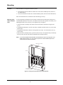
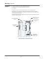
Download Simplex 4100ES-S1 Installation guide
Transcript
4100/4120-Series Digital Alarm Communications Transmitters Installation Instructions Introduction This publication describes the installation procedure for the following: • 4100/4120-0155 Serial Digital Alarm Communications Transmitter (DACT) (non-4100U/4100ES) • 4100-6052 DACT (4100U/4100ES) _________________________________________________________________________________ Related Documentation • • • • • Field Wiring Diagram for 4100 Power Limited (841-731) or, Field Wiring Diagram for 4100 Non Power Limited (841-995) 4100ES Fire Alarm System Installation Guide (574-848) T-Link TL250/TL300 Network Internet Alarm Communicator #29034631 C900V2 Installation Guide Dialer Capture Ethernet Module # F01U003472-02 _________________________________________________________________________________ Content This publication covers the following topics: Topic Page Cautions and Warnings 2 Introduction 3 Power-Limited Wiring Guidelines 6 Connecting to the Phone Lines (not required when TL300 is used) 7 Configuring the DACT 8 Data and Power Wiring 10 Mounting 13 Programming 15 Testing 16 Compatibility 17 © 2005-2011 SimplexGrinnell LP. All rights reserved. Specifications and other information shown were current as of publication and are subject to change without notice. Simplex and the Simplex logo are trademarks of Tyco International Ltd. and its affiliates and are used under license. 574-836 Rev. N Cautions and Warnings Cautions and Warnings READ AND SAVE THESE INSTRUCTIONS. Follow the instructions in this installation manual. These instructions must be followed to avoid damage to this product and associated equipment. Product operation and reliability depend upon proper installation. DO NOT INSTALL ANY SIMPLEX® PRODUCT THAT APPEARS DAMAGED- Upon unpacking your Simplex product, inspect the contents of the carton for shipping damage. If damage is apparent, immediately file a claim with the carrier and notify an authorized Simplex product supplier. ELECTRICAL HAZARD - Disconnect electrical field power when making any internal adjust- ments or repairs. All repairs should be performed by a representative or authorized agent of your local Simplex product supplier. STATIC HAZARD - Static electricity can damage components. Handle as follows: • Ground yourself before opening or installing components. • Prior to installation, keep components wrapped in anti-static material at all times. FCC RULES AND REGULATIONS -PART 15 - This equipment has been tested and found to comply with the limits for a Class A digital device pursuant to Part 15 of the FCC Rules. These limits are designed to provide reasonable protection against harmful interference when the equipment is operated in a commercial environment. This equipment generates, uses, and can radiate radio frequency energy and, if not installed and used in accordance with the instruction manual, may cause harmful interference to radio communications. Operation of this equipment in a residential area is likely to cause harmful interference in which case the user will be required to correct the interference at his own expense. 2 Introduction Overview Digital Alarm Communications Transmitter’s (DACT) are option cards that mount within 4100 Fire Alarm Control Panels (FACP). The 4100/4120-0155 Serial DACT, available for the 4100 (non-4100U/4100ES) only, can be programmed to notify the central station when specified events occur, or to report changes to a specific point’s status. The 4100-6052 DACT, available for the 4100U and 4100ES, has four main functions: • Notifying the central station when specified events occur • Reporting changes to a specific point’s status to the central station • Connecting to a DSC TL300 transmitter for connection to a central station via Ethernet line (UL and ULC) • Connecting to a Bosch C900V2 transmitter for connection to a Central Station through the Ethernet line (UL only) Phone Line Transmission The DACT receive system status messages from the host FACP, and communicate the information over the public telephone network to a Digital Alarm Communications Receiver (DACR) at the central station. The DACT is connected to two telephone lines, which are not required to be "dedicated" to the fire alarm. They may be connected to other telecom equipment, but the DACT must be wired electrically "first" in the chain as shown in Figure 5. The telephone lines must be wired to DACT terminals TB1-2/TB1-3 and TB2-2/TB3-3 to ensure that the DACT can disconnect other telecom equipment in case the phone line is in use during an emergency. The other telecom equipment is wired to TB1-1/TB1-4 and TB2-1/TB2-4. The DACT is programmable for pulse or tone dialing , see the ES PanelProgrammer’s Manual (574-849) for the programming instructions. The DACT detects whether or not a telephone line is connected to both inputs. A 4100 system trouble is signaled, both audibly and visibly, if either line is disconnected. TL300 Ethernet Transmission (UL and ULC) The DACT receives system status messages from the FACP using CID codes only. Then, it communicates the information over an Ethernet connection to a DACR at the central station. The telephone connections on the DACT are connected together, (R1 (TB1-2) to R2 (TB2-2) and T1 (TB1-3) to T2 (TB2-3). Then, a single pair is connected to the TL300 (T1 (TB1-2 of DACT) to T1 and R1 (TB2-3 of DACT) to R1). Since an actual telephone line is not used, TB1-1/TB1-4 and TB2-1/TB2-4 are not used. The correct IP address and other modes are programmed into the TL300, see programming section later in this manual. When the DACT goes off-hook, the TL300 sends a dial tone to the DACT. The panel dials the number of the central station and the TL300 send all the correct tones so that the DACT believes it is connected to the central station via a telephone line. Upon receipt of the information the TL300 sends the information to the central station via the Ethernet connection. The TL300 must be mounted within 20 feet, in the same room, in conduit. Power for the TL300 comes from the FACP. Refer to T-Link TL300 Installation Manual 29034531 for further details. 3 Introduction (continued) C900V2 Ethernet Transmission (UL only) The DACT receives system status messages from the 4100U/4100ES using the codes listed on page 17. It then communicates the information over an Ethernet connection to a DACR at the central station. The telephone connections on the DACT are connected together; R1 (TB1-2) to R2 (TB2-2) and T1 (TB1-3) to T2 (TB2-3). Then a single pair is connected to the C900V2. Note: Since an actual telephone line is not used, TB1-1/TB1-4 and TB2-1/TB2-4 are not used. The correct IP address and other modes are programmed into the C900V2, refer to the Installation and Programming manual supplied with the C900V2. When the DACT goes off-hook, the C900V2 sends a dial tone to the DACT. The panel dials the number of the central station and the C900V2 sends all the correct tones so that the DACT believes it is connected to the central station through the telephone line. Upon receipt of the information, the C900V2 sends the information to the central station through the Ethernet connection. The C900V2 must be mounted within 20 feet of the FACP and in the same room as it. It must also be enclosed in a conduit or be equivalently protected against mechanical changes. _________________________________________________________________________________ Illustration Figure 1 is an illustration of Serial DACT card 566-787. The circuit boards for all DACTs described in this publication are identical. 6&5(: 7(50,1$/6 3+21(/,1( &211(&7,216 86&$102'( -803(5 '(9,&($''5(66 6:,7&+6: 3$11(/7528%/( /('/(' &2007528%/( /('/(' 32:(5&200 7528%/(/(' /(' 352*5$00(5 6:,&+6: 6(/)7(67 6:,7&+6: 352*5$00(5 &211(&7,21 723&3 228&200 &211(&7253 58,&211(&725 3 58,&211(&725 3 58,&200 6:,7&+6: Figure 1. Serial DACT card 566-787 Continued on next page 4 Introduction (continued) LEDs Refer to Table 1 for DACT LED indicators. Table 1. LED Indications LED Possible State Not Illuminated. The system is not receiving DC power, or the power-up self-test failed. Power (LED 1) Green LED On Steady. The DACT is receiving DC power and is operational. Flashing. DACT is dialing up (or attempting to dial up) the central station. Not Illuminated. No communication errors are being detected. On Steady. DACT cannot communicate with the Central Station. All Communication dialing attempts have failed. Trouble (LED 2) Single Flashes. DACT detects a line fault on phone line 1. Yellow LED Double Flashes. DACT detects a line fault on phone line 2. Alternating Flashes. DACT detects line faults on both phone lines when LED alternates between single and double flashes. Not Illuminated. DACT is communicating with the host panel. Panel Communication On Steady. DACT cannot communicate with the host panel. Trouble (LED 3) Fast Flashes. There is a version mismatch between the host Yellow LED panel and the DACT. Specifications Refer to Table 2 for DACT electrical requirements and environmental limitations. Table 2. Specifications Electrical Specifications Voltage 19 - 33V dc, 2V p-p max. ripple at 120 Hz Current Standby mode: 60 mA maximum Report mode: 126 mA maximum Programming mode: 45 mA maximum Ground Isolation DC resistance between 0 V and earth ground must exceed 1 Megohm Environmental Specifications Temperature 32o to 120o F (0o to 49o C) Humidity Up to 93% relative humidity at 90o F (32o C) 5 Power-Limited Wiring Guidelines Power-limited Wiring Guidelines 
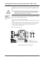
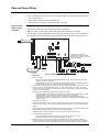
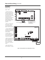
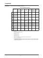
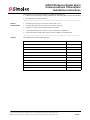
• Non-power limited field wiring (AC power, batteries, City connection) must be installed and routed in the shaded areas shown in Figure 2. • Power-limited field wiring must be installed and routed in the non-shaded areas shown in Figure 2, with the exception of City wiring. • Excess slack should be kept to a minimum inside the back box enclosure. The wiring should be neatly dressed and bundled together using the wire ties provided with the equipment. Anchor power-limited wiring to tie points, as shown in Figure 2. &21'8,7(175$1&( )2532:(5/,0,7(' :,5,1* &21'8,7(175$1&( )2512132:(5 /,0,7(':,5,1* 12132:(5 /,0,7(':,5,1* 32:(5/,0,7(' :,5,1* 7,(32,17 /2&$7,210$<9$5< Figure 2. Power-limited wiring • Tie the wiring located between bays to the internal wiring troughs, if applicable. • When powering remote units or switching power through relay contacts, power for these circuits must be provided by a power-limited power supply that is listed for fire-protective signaling use. 6 Connecting to the Phone Lines (not required when TL300 is used) Before Installation Have the telephone company install two telephone lines, each terminated with an RJ-31X jack immediately above or as close as possible to the fire alarm control panel. Be prepared to supply the telephone company with the FCC information printed on the FCC and/or Industry Canada label. Caution: Do not direct-connect the DACT to a coin telephone or party line. Be sure that the telephone lines that you are connecting the DACT to are standard analog lines and not digital (PBX), party, or coin telephone lines. The line must not have any Telephone Company (TELCO) features such as “CALL WAITING”, etc. Connecting the 2080-9047 Harness to the DACT and RJ-31X Jacks The connection to the RJ-31X jacks must be made via the modular jack in installations where the DACT will share the telephone line with premises phones or other equipment. Use two Simplex harnesses for this connection - 2080-9047 (14 feet). Refer to Figure 3 as you read the following instructions. 1. Connect the 2080-9047 Harness to the TB3 and TB4 screw terminals on the DACT as shown in Figure 3. 2. The two telephone line harnesses must take separate paths from the host FACP to the RJ-31X blocks. Use cable tie-wraps to provide strain relief for these cables. Secure the cables to any standoff or metal fixture along the cable run between the DACT and the panel exit. 3. Connect one harness to each RJ-31X jack. TELCO wiring is supervised. 4 )0( 'REY 4 )0 'REEN $IRECT # ONNECT # ORD 2 ED 2 ).' "LUE 2 ).'( )NCOMING 4 ELEPHONE ,INE 0ROTECTOR Note: 2 * 8 4 2 ", / "+ 2 ' 9 ". 3 2 ! 2 4 ! 4 * ACK # ONFIGURATION 4 W O S HORTING BARS COMPLETE THE CONNECTION OF PREMIS ES PHONES TO THE INCOMING LINE UPON REMOVAL OF THEDIRECTCONNECT PLUG 3 HORTING BARS OPEN UPON INS ERTION OF THE 0REMIS ES 0HONES PLUG 4 ES TING DIRECT CONNECT CORD PLUGGED IN # OMMUNICATOR ! CTIVE 4 ERMINALS 4 )0 AND 2 ).' S HOULD READ 6 # OMMUNICATOR )NACTIVE - EAS UREMENT ACROS S 4 ERMINALS AND S HOULD READ APPROXIMATELY 6 Figure 3. Telephone system connection (each line) 7 Configuring the DACT Overview Configuring the DACT consists of: • • • • Setting the correct communication mode Specifying whether the DACT is in Test mode Specifying whether the DACT should be ready to download new programming data Setting the device address This section covers all of these settings. Setting the COMM switch Make sure switch SW1 is in the DOWN position. This specifies the 4100 communications mode. Setting the Test Switch Make sure switch SW2 is in the DOWN (off) position. This should be used for testing the DACT, and then returned to the DOWN position. See “Testing.” Setting the Programmer Switch To download data, switch SW3 must be in the UP position. During normal DACT operation, SW3 must be in the DOWN position. See the section on Testing and Compatibility. Setting the Address The device address is set via DIP switch SW4, which is a bank of eight switches. From left to right (see Figure 4) these switches are designated as SW4-1 through SW4-8. The function of these switches is as follows: • SW4-1. This switch sets the baud rate for the internal 4100 communications line running between the card and the 4100 CPU. Set this switch to ON. • SW4-2 through SW4-8. These switches set the card’s address within the 4100 FACP. Refer to Table 3 for a complete list of the switch settings for all of the possible card. addresses. Note: You must set these switches to the value assigned to the card by the Programmer. &200%$8'5$7( 6:,7&+6: 0867%(6(77221 )25',36:,7&+(66: 7+528*+6:6(77+( &$5'$''5(66),*85( 6+2:6$1$''5(662) 2)) 21 Figure 4. DIP switch SW4 Continued on next page 8 Configuring the DACT (Continued) Setting the address Table 3. DACT card switch settings $GGUHVV 6: 6: 6: 6: 6: 6: 6: $GGUHVV 6: 6: 6: 6: 6: 6: 6: 21 21 21 21 21 21 2)) 21 2)) 2)) 2)) 2)) 21 2)) 21 21 21 21 21 2)) 21 21 2)) 2)) 2)) 2)) 2)) 21 21 21 21 21 21 2)) 2)) 21 2)) 2)) 2)) 2)) 2)) 2)) 21 21 21 21 2)) 21 21 2)) 21 21 21 21 21 21 21 21 21 21 2)) 21 2)) 2)) 21 21 21 21 21 2)) 21 21 21 21 2)) 2)) 21 2)) 21 21 21 21 2)) 21 21 21 21 21 2)) 2)) 2)) 2)) 21 21 21 21 2)) 2)) 21 21 2)) 21 21 21 2)) 21 21 2)) 21 21 21 2)) 21 2)) 2)) 21 21 21 2)) 2)) 21 2)) 21 21 21 2)) 2)) 2)) 2)) 21 21 2)) 21 21 21 2)) 21 21 2)) 21 21 2)) 2)) 21 21 2)) 21 2)) 21 2)) 21 21 2)) 21 2)) 2)) 2)) 21 21 2)) 2)) 21 21 2)) 21 21 2)) 2)) 21 2)) 2)) 21 21 2)) 2)) 2)) 21 2)) 21 21 2)) 2)) 2)) 2)) 2)) 21 2)) 21 21 21 21 2)) 21 2)) 21 21 21 2)) 2)) 21 2)) 21 21 2)) 21 2)) 21 2)) 21 21 2)) 2)) 2)) 21 2)) 21 2)) 21 21 2)) 21 2)) 21 2)) 21 2)) 2)) 21 2)) 21 2)) 2)) 21 2)) 21 2)) 21 2)) 2)) 2)) 2)) 21 2)) 2)) 21 21 21 2)) 21 2)) 2)) 21 21 2)) 2)) 21 2)) 2)) 21 2)) 21 2)) 21 2)) 2)) 21 2)) 2)) 2)) 21 2)) 2)) 2)) 21 21 2)) 21 2)) 2)) 2)) 21 2)) 2)) 21 2)) 2)) 2)) 2)) 21 2)) 21 2)) 2)) 2)) 2)) 2)) 2)) 2)) 21 21 21 21 21 2)) 2)) 21 21 21 21 2)) 2)) 2)) 21 21 21 2)) 21 2)) 2)) 21 21 21 2)) 2)) 2)) 2)) 21 21 2)) 21 21 2)) 2)) 21 21 2)) 21 2)) 2)) 2)) 21 21 2)) 2)) 21 2)) 2)) 21 21 2)) 2)) 2)) 2)) 2)) 21 2)) 21 21 21 2)) 2)) 21 2)) 21 21 2)) 2)) 2)) 21 2)) 21 2)) 21 2)) 2)) 21 2)) 21 2)) 2)) 2)) 2)) 21 2)) 2)) 21 21 2)) 2)) 21 2)) 2)) 21 2)) 2)) 2)) 21 2)) 2)) 2)) 21 2)) 2)) 21 2)) 2)) 2)) 2)) 2)) 2)) 2)) 21 21 21 21 2)) 2)) 2)) 21 21 21 2)) 2)) 2)) 2)) 21 21 2)) 21 2)) 2)) 2)) 21 21 2)) 2)) 2)) 2)) 2)) 21 2)) 21 21 2)) 2)) 2)) 21 2)) 21 2)) 2)) 2)) 2)) 21 2)) 2)) 21 2)) 2)) 2)) 21 2)) 2)) 2)) 21 2)) 21 21 21 21 21 21 2)) 21 21 2)) 21 21 21 2)) 21 2)) 21 21 21 21 2)) 21 2)) 2)) 21 21 21 2)) 2)) 21 21 21 21 21 2)) 2)) 21 2)) 21 21 21 2)) 2)) 2)) 21 21 21 21 2)) 2)) 2)) 2)) 21 21 2)) 21 21 21 21 21 21 2)) 21 21 21 2)) 21 21 2)) 21 21 2)) 21 21 21 2)) 21 21 2)) 2)) 21 21 2)) 21 2)) 21 21 21 21 2)) 21 2)) 21 2)) 21 21 2)) 21 2)) 2)) 21 21 21 2)) 21 2)) 2)) 2)) 21 21 2)) 2)) 21 21 21 21 21 2)) 2)) 21 21 2)) 21 21 2)) 2)) 21 2)) 21 21 21 2)) 2)) 21 2)) 2)) 21 21 2)) 2)) 2)) 21 21 21 21 2)) 2)) 2)) 21 2)) 21 21 2)) 2)) 2)) 2)) 21 21 21 2)) 2)) 2)) 2)) 2)) 21 2)) 21 21 21 21 21 21 2)) 21 21 21 21 2)) 21 2)) 21 21 21 2)) 21 21 2)) 21 21 21 2)) 2)) 21 2)) 21 21 2)) 21 21 21 2)) 21 21 2)) 21 2)) 21 2)) 21 21 2)) 2)) 21 21 2)) 21 21 2)) 2)) 2)) 21 2)) 21 2)) 21 21 21 21 2)) 21 2)) 21 21 2)) 21 2)) 21 2)) 21 2)) 21 21 2)) 21 2)) 21 2)) 2)) 21 2)) 21 2)) 2)) 21 21 21 2)) 21 2)) 2)) 21 2)) 21 2)) 21 2)) 2)) 2)) 21 21 2)) 21 2)) 2)) 2)) 2)) 21 2)) 2)) 21 21 21 21 21 2)) 2)) 21 21 21 2)) 21 2)) 2)) 21 21 2)) 21 21 2)) 2)) 21 21 2)) 2)) 21 2)) 2)) 21 2)) 21 21 21 2)) 2)) 21 2)) 21 2)) 21 2)) 2)) 21 2)) 2)) 21 21 2)) 2)) 21 2)) 2)) 2)) 21 2)) 2)) 2)) 21 21 21 21 2)) 2)) 2)) 21 21 2)) 21 2)) 2)) 2)) 21 2)) 21 21 2)) 2)) 2)) 21 2)) 2)) 21 2)) 2)) 2)) 2)) 21 21 9 Data and Power Wiring Wiring Guidelines Review the following guidelines before wiring P1 and P4 of the DACT. • If U.T. motherboard 565-274 or 565-213 is wired to the DACT, jumper P4 on the motherboard must be at position 13. • Unless otherwise noted, wiring is not supervised. • Cut and strip wire harnesses to the proper length, if required. Wiring an Serial DACT Card Into the System Note: Unless otherwise noted, wiring is not supervised. 1. Wire the Serial DACT into the system in accordance with Figure 5. 2. Route the TELCO cables using separate paths from panel exit to RJ-31X modules 3. Use the cable tie-wraps (supplied) to provide strain relief for these cables. Secure the cables to any standoff or metal fixture along the cable run between the Serial DACT and the panel exit. 3 6HULDO'$&7 3 3 6: &$1 3 6: 86 6: 3 6: 6: /(' /(' /(' /LQH /LQH 7% 7% Configuration not used when connected to a TL300 or a C900V2. See the following pages for TL300 and C900V2 connections 56 7['2XW &RPPRQ 5[',Q Figure 5. Serial DACT card 0566-787 Figure 5 Notes: 1. Factory connections: • 4100: Connect to the nearest 4100/4120 Motherboard P2/P3 plugs: white wire socket to P3, blue wire socket to P2. Observe orientations. • 4100U/4100ES: Connect to the nearest 4100/4120 Motherboard P2/P3 plugs or /4100ES Motherboard P7/ P8 plugs: white wire socket to P7, blue wire socket to P8. Observe orientations. 2. Power-limited wiring. Route the TELCO cables from the terminal blocks to the left side of panel, and exit at the top-left of enclosure. Using the 2080-9046 Harness (7 ft. cable), -9047 Harness (14 ft. cable), or equivalent, connect to the TELCO jacks. Splice as required (using a minimum of 22 AWG wire) to complete the desired span. The TELCO wiring is supervised. 3. Cable connection to Serial DACT Programmer (only present during set-up). • 4100: Switch SW3 must be placed in the ON position for the download. When the download is completed, place switch SW3 in the OFF position for normal operation. Cable is not supervised. • 4100U/4100ES: Connection to the Programmer is not required for 4100U/4100ES installations. Programmer switch SW3 must remain in the OFF position. SDACT program is updated automatically after system download. 4. Card Address Switch (SW4). 5. Programmer Switch (SW3). Slide switch SW3 to the ON (up) position to program and download. Return to OFF position for normal operation. Note: “Up” and “down” switch references become “in” and “out” after the board is installed. 6. SDACT Manual Test Switch (SW2). Slide switch SW2 to the ON (up) position for a manual test that will dial and attempt DACR communication. Return to the OFF position for normal operation. 7. COMM Switch (SW1). Switch SW1 must be in the down position for 4100/4120 communication. 8. U.S./Canada Operating Mode Jumper: • U.S. mode is selected when there is no jumper or jumpers are connected to pin 1 and 2. • Canada mode is selected when jumpers are connected to pin 2 and 3 9. Bootloader Switch (SW5). The bootloader switch should be left in the off position for SDACT operation. If necessary, It can be used to allow a field upgrade to the SDACT firmware. Instructions for using the bootloader will be included with any required firmware upgrades. (See Technical Support web site for future availability.) 10 Data and Power Wiring (Continued) Wiring the DACT to the TL300 Wire the DACT to the TL300 in accordance with Figure 6 and Figure 7. DSC FC5003 Cabinet T-Link TL300 12V GND TX Network GND BLK GRN PGM2 GND IN4 IN3 T1 GND Earth RX RED YEL IN2 R1 PGM1 IN1 #18 - #26 awg EOLR for IDC See note 3 #18 - #22 awg 3 #18 - #22 awg See note 2 #18-22 awg 150mA max See note 4 4 Notes: 1. Panel containing the TL300 to be mounted within 20 feet of the FACP and mounted in the same room. The wiring to the FACP to be in conduit. Connect to the FACP, IDC to monitor Ethernet connection failure. Connect to FACP, Relay N.O. contact. Relay programmed to energize when there is a telephone Line 1 or 2 trouble in the Serial DACT. To Auxiliary Power terminals 24V and 0V of the FACP SPS. 2. 3. 4. See note 4 IAM Serial DACT 0566-787 P1 P6 P2 SW5 CAN P3 SW1 US SW4 P4 SW2 SW3 LED1 LED2 LED3 1 #18 - #26 awg Figure 6. Wiring the DACT to the TL300 11 TB1 TB2 1 Data and Power Wiring (Continued) Wiring the DACT to the C900V2 DACT (UL only) %RVFK $( HQFORVXUH 6HH QRWH Figure 7 Notes: 3DQHO &9 3 1. A Bosch C900V2 in a Bosch AE2 enclosure must be mounted within 20 feet of the FACP and be in the same room as it. The wiring to the FACP must be enclosed in the conduit or be equivalently protected against mechanical damage. The cabinet must be grounded. 6 5- 6HH QRWH 3 7HOFR 29 287 287 287 287 ,1 6HHQRWH (7+(51(7 ,1 29 ,1 9 VHH QRWH (2/5 DZJ DZJ P$ PD[LPXP 2. Wire the C900V2 to the FACP’s IDC to monitor LAN and board failure. Make connections as shown. 6HULDO'$&7 3 3. Consult installation guide F01U003472 for programming and setup instruction for the C900V2 3 3 4. T1AUX , R1AUX, T2Aux and R2AUX are not used. Auxiliary equipment cannot be used either. 6: &$1 3 6: 86 6: 3 6: 6: /(' /(' /(' 5. Wire the C900V2 to the 4100U/4100ES SPS Aux Power terminal, TB3-1 0V, TB3-2 +24. Maximum current draw of C900V2 is 280ma. 7% 7% 5HG 6HHQRWH 6. Wire jumper TB1-2 to TB2-2 and TB2-3 to TB3-3. Figure 7. Wiring the DACT to the C900V2 DACT (UL only) 12 *UHHQ Mounting Overview Both assemblies are designed for different systems. • The 4100/4120-0155 Serial DACT mounts into a non-4100U/4100ES systems (with 297591xx Back Boxes). • The 4100-6052 DACT mounts into a 4100U/4100ES systems (with 2975-94xx Back Boxes). This section describes how to mount the cards into both types of bays. Mounting Serial DACT 4100/41200155 Use the instructions and figure below to mount a 4100/4120-0155 Serial DACT bracket into a 4100 Back Box (PID series 2975-91xx). The directions are the same regardless of whether you’re installing the DACT into a CPU bay or an expansion bay. See Figure 8. 1. Secure the DACT assembly to the chassis. Secure the bracket to the chassis using four #6 screws. 2. (If applicable) Disconnect one of the two battery terminals, and then remove AC power at the power source. 3. (If applicable) Disconnect and remove the optional city card(s). Tie off and remove the city circuit wiring. 4. Place the DACT assembly into any open slot in the CPU bay or an expansion bay, but if the bay has relay cards, the relay cards must be installed in the far right of the bay. Note: It is recommended that the Serial DACT be installed in the far left or far right slot. This module does not have a J1 or P1 connector (which are used to distribute power and communications to adjacent modules.) 2 %')3 4 2 ! 4 )/. ,! "%, # # $! # 4 # # $! # 4 "2 ! # + %4 # /5,$ ! ,3 / '/ (%2 % Figure 8. Installing the motherboard into a 4100 back box 13 Mounting (Continued) Mounting DACT 4100-6052 • The 4100-6052 DACT can only be installed in the CPU bay. • The DACT must be the leftmost assembly in the CPU bay. • See Figure 9. 1. Disconnect AC power at the source. Disconnect the + (red) wire from the battery. 2. Install harness 733-929 as shown. Connect from P1 on the DACT to the two 4-position connectors on the CPU motherboard. The blue wire to the top connector (P8) and the white wire to the bottom connector (P7). 3. Secure the DACT bracket to the leftmost slot on the chassis using four #6 standoffs (screwed to the chassis) and four #6 screws. 0$67(5&21752//(5 %2$5' 3:5&200+$51(66 &38027+(5%2$5' '$&7 02'8/( %$<72%$< +$51(66 3:5 &2006 Figure 9. Mounting the 4100-6052 DACT module 14 Programming 4100/4120 Programming The DACT must be selected in the Programmer. Refer to Serial DACT Installation and Programming Instructions (574-090) for specific programming requirements. 4100U/4100ES Programming The correct DACT card must be selected in the 4100U/ES Panel Programmer. Refer to the ES Panel Programmer’s Manual (574-849). Additional Programming When a DACT connects to a TL300, additional programming is required. 1. To monitor the relay contact of a relay located in the cabinet with the TL300. This relay will energize and open the IDC circuit when the Ethernet connection to the Central station has been broken. 2. Program a Relay so that it will energize on the telephone Line 1 or Line 2 fault. The N.O. contacts will connect to GND and AN4 of the TL300. An example equation is below. The Serial DACT is at address 9 and the Aux relay on the SPS (Aux 3) is used. INPUTS] STATUS TBL 9-0-3 | CARDSTAT | CSP | PHONE LINE 1 OR STATUS TBL 9-0-4 | CARDSTAT | CSP | PHONE LINE 2 [END INPUTS] [OUTPUTS] TRACK ON PRI=9,9 AUX3 | RELAY | RELAY | AUX RELAY CARD 1 RELAY CKT AUX3 [END OUTPUTS] TL300 Programming Refer to T-Link TL250/TL300 Network Internet Alarm Communicator #29034631 for information concerning the programming of the TL300. In addition to the required programming in the manual for the ULC compliance: • Section 035 PGM1 needs to be Enabled. • Section 039 needs to be code 98 24 hr. Panel Absent. 15 Testing Testing When the DACT is connected to the system, its operations should be tested with the manual TEST switch (SW1). The manual test ensures that: • The phone line is working. • The DACT has been programmed with a correct phone number. • Communications with the central station work. When the manual switch is activated, the DACT dials the central station and transmits a "manual test" event code to the DACR located at the central station. During the dialing process, the green power/comm LED (LED1) should change from steady on to flashing, indicating that the DACT is attempting communications with the central station. The green LED should change back from flashing to the steady on state when communication is established. When the green LED returns to steady on, return the TEST switch to the OFF position. 16 Compatibility Compatibility Refer to Table 4 for compatibility information. Table 4. Compatibility information Comm. Format Osborne/ ADEMCO Silent Hoffman 685 Knight 9000 Quickalert (Notes 2, 6) Model II YES YES YES (Note 3) SUR-GARD FBI BOSCH CP220FB RADIONICS MLR2-DG (Note 7) (Notes 5, 6) 6500/6600 (Notes 6, 8) YES YES YES 1 3/1 Standard 1800/2300 Hz (Note 1) 2 3/1 Standard 1900/1400 Hz (Note 1) YES YES YES (Note 3) YES YES YES 3 4/2 Standard 1800/2300 Hz (Note 1) YES YES YES (Note 3) YES YES YES 4 4/2 Standard 1900/1400 Hz (Note 1) YES YES YES (Note 3) YES YES YES 5 ADEMCO CONTACT ID SIA YES YES NO YES YES NO YES (Note 4) NO 7 RADIONICS BFSK 1800/2300 Hz YES YES YES (Note 3) YES YES NO/YES (Notes 6, 8) YES NO/YES (Note 6) YES YES 8 RADIONICS BFSK 1900/1400 Hz YES YES YES (Note 3) YES YES 6 YES Table notes: 1. 10 and 20 PPS (Pulses Per Second) 2. With 685-8 Line Card 3. With 9032 Line Card 4. With 9004 Line Card 5. With Rec-11 Line Card 6. With or without D6680 Network Ethernet Adapter in D6600 (4100U/4100ES) 7. DDC TL300 (4100U/4100ES) 8. The 4100-6052 DACT is suitable for Proprietary Protected Premises Service when communicating with the 6600 receiver via Ademco Contact ID format and the 6600 is also monitored by the 4190-8403 Truesite Workstation serving as the operator interface. 17 574-836 Rev. N