1
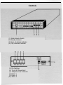
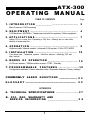
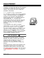
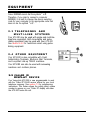
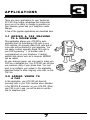
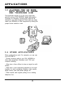
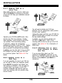
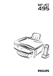
TM
Versa-Link
ATX-300
Online Operating
Instructions
www.faxswitch.com
Controls
(1.) Mode Selector Switch
(2.) Standby Indicator
(3.) Semi - Automatic Indicator
(4.) Fully Automatic Indicator
10
9
8
7
(5.) Dip Switches
(6.) 12 volt AC Power Input
(7.) Telephone Line Connector
(8.) Device 1
(9.) Device 2
(10.) Device 3
OPERATING
ATX-300
MANUAL
TABLE OF CONTENTS
Page
1. I N T R O D U C T I O N ...................... ....................................
2
Basic Features / Call Processing
2 . E Q U I P M E N T ..................................................................
4
FAX Machines / MODEMS / Telephones and multi-line systems / Other equipment
3 . A P P L I C A T I O N S .......................... .................................
7
4 . O P E R A T I O N ............................ ......................................
9
Adding FAX to a voice line / Expanding a FAX line / Allowing two or more data
devices to share one line
Outbound calls / Manual transfer / Automatic FAX transfer / CALL OPTI-MIZER
5 . I N S T A L L A T I O N . . . . . . . . . . . . . . . . . . . . . . . . . . . . . . . . . . . . . . . . . . . . . . . . . . . . . . . . . . . 13
Your phone line / Telephone systems / Multi-line phones / Attaching FAX and
data devices
6 . MODES
OF
OPERATION ......................................... 1 6
AUTOmatic answer / SEMIautomatic answer / STBY / Standby
7. PROGRAMMABLE
F E A T U R E S . . . . . . . . . . . . . . . . . . . . . . . . . .1 9
COMMONLY
Q U E S T I O N S ......................... 2 4
Configuration switches / Device selection codes / Expanded features / Factory settings
ASKED
G L O S S A R Y .......................................................................
2 5
APPENDICES
A. TECHNICAL SPECIFICATIONS .. . . . . . . . . . . . . . . . . . . . . . . . . 2 7
B. FCC, DOC, WARRANTY AND
SERVICE INFORMATION . . . . . . . . . . . . . . .. . . . . . . . . . . . . . . . . . . . . . . . . . 2 8
VERSA-LINK
ATX-300
1
3rd Edition,©1992 Muti-Link, Inc.
INTRODUCTION TO THE WORLD
CALL
PROCESSING
Your Versa-Link ATX-300 is a powerful Computerized Call Processor that allows several telephone
devices to share a single phone line. Versa-Link is
compatible with standard telecommunication and
office equipment including: Facsimile (FAX)
machines, computer MODEMS, PC FAX Boards,
single and multi-line telephone systems, answering
machines, WATS lines, phone mail systems, credit
approval systems, and loop start TELEX equipment.
Versa-Link allows you to expand your present
communications network without installing an
expensive dedicated phone line for each device.
Versa-Link provides for greater utilization of phone
lines and office equipment.
1 .1 B A S I C
FEATURES
Versa-Link is a 24-hour communications control
center that automatically analyzes and routes
incoming calls to the proper equipment. Your VersaLink ATX-300 permits a caller to remotely access
your telephone, FAX machine, computer MODEM, or
other equipment you may have attached. Standard
features include: - Auto FAX Detection - CALL
OPTI-MIZER - Automatic Ring-through to your mostused equipment - Manual Transfer - Calling Party
Hang-up Detect.
CALL OPTI-MIZER is a unique feature that makes
your phone line look more like a dedicated voice line
to voice callers, and more like a dedicated data line
to FAX or computer MODEM callers.
Calls can be manually transferred at any time by
either the caller or the called party.
Versa-Link’s data protection feature allows you to
transmit FAX or computer MODEM data without the
fear of someone disturbing the transmission by
picking up an extension phone. It also gives you
peace of mind knowing that your voice call will never
be interrupted by a FAX or MODEM.
VERSA-LINK
ATX-300
2
Another unique feature is Versa-Links surge
suppressor, which provides added protection from
lightning strikes and voltage surges that could
damage your sensitive communications equipment.
1.2 C A L L P R O C E S S I N G
Call processing is the task of routing telephone voice
and data calls to one of several destinations. Your
phone company can be considered a very large call
processor.
To better understand the principles behind call
processing, consider the following example:
l A receptionist who answers all incoming calls
(in this case, the Versa-Link ATX-300)
l A Customer Service Agent.
l A sales agent.
l A bookkeeper.
When a phone call comes in, the Versa-Link acts as
a receptionist and answers the call. If the caller
requests the sales agent or the bookkeeper by
dialing an access code, the Versa-Link transfers the
call to the proper party without disturbing anyone
else. If no code is dialed, the call is automatically
directed to the customer service agent for
information and further routing. The customer
service agent may re-direct calls to the sales agent
or bookkeeper by entering the proper access code.
Your ATX-300 can be used to process calls to your
voice and data equipment, just as it did in the above
example. If you are adding FAX and a computer
MODEM to a voice line, you have:
l A Versa-Link ATX-300 that answers all calls
and transfers them to the proper device.
l A telephone system that handles most calls.
l A FAX machine.
l A computer MODEM.
This is just one application. As you will see, your
Versa-Link is not just a switch. It’s a very smart call
processor that does exactly what it’s told to do, and
does it very well.
VE R S A - L I N K
ATX-300
3
6
EQUIPMENT
Your Versa-Link ATX-300 is compatible with virtually
all modern telecommunications equipment, including
single and multi-line telephones. Because your
ATX-300 is installed between your telephone system
and the phone company, it can direct all your telephone traffic to the proper equipment. The most
popular types of equipment used with a Versa-Link
ATX-300 are described below.
2.1 FAX MACHINES
Your ATX-300 has special features that work
extremely well with FAX machines and PC FAX
Boards. The Auto FAX Detection feature allows most
FAX calls to transfer to your FAX machine
automatically.
The vast majority of FAX machines sold today have
the ability to dial the number of the receiving FAX
from memory, and then identify itself as a FAX
machine with a tone (called CNG tone or AUTO-FAX
tone). It will then continue to identify itself until the
called FAX answers the call. When an ATX-300 is
used at the receiving end, it can detect this FAX
identification tone, and automatically transfer the call
to the FAX machine on the receiving end, without
ringing the telephone.
Occasionally, calls will come from a FAX machine
without a FAX identification tone. This may happen if
the calling person is using an older FAX machine, or
dials the number manually using the FAX handset. In
most applications, calls without this auto-FAX tone
will be routed to your telephone system. The call can
be manually transferred to the FAX machine by
dialing * 2 (or another code, if re-programmed) on
your telephone keypad. Either the caller or the
person who answers can transfer the call. See
section 4.2.2 for details of operation.
VFRSA-LINK A T X - 3 0 0
4
EQUIPMENT
If possible, ask people who send you FAX messages
to program your number into their FAX machine’s
memory. This will allow FAX calls to always be
processed automatically.
2.2 COMPUTER MODEMS
Your ATX-300 is compatible with all dial-up MODEMS.
Usually, MODEMS are attached to the DEVICE 3
connector of your ATX-300. Your ATX-300 will
transfer incoming calls to your MODEM when the
calling MODEM dials * 3 (or another code, if
re-programmed) after the call has been answered
by your Versa-Link. The data protection feature
prevents interruptions from other telephone
equipment.
If your MODEM is only used for out-bound
communication, you do not need to be concerned
with the device selection code for the MODEM.
The device selection code for your MODEM is best
dialed by the calling MODEM. When calling your
MODEM attached to DEVICE 3, with the ATX-300’s
factory programming, the dialing command for a
Hayes-compatible MODEM would be:
I
ATDT 1 203 555 5678 , , ,
3
I
The commas will generate pauses in the dialing
MODEM. The number of pauses may need to be
changed to allow enough time for the call to be
switched through the telephone company,
particularly if the calling MODEM is dialing longdistance.
The device selection codes can be changed- up to
seven digits to add security to any system. Your
ATX-300 will restrict access to only those callers
who dial the right device selection code. See section
7, PROGRAMMABLE FEATURES, to change this
code.
VERSA-LINK
ATX-300
5
EQUIPMENT
Some MODEMS cannot dial the symbols * or #.
Therefore, if you plan to connect a computer
MODEM, it is best to change the device selection
code for your computer to an appropriate code that
does not use the symbols * or # .
2.3 TELEPHONES AND
MULTI-LINE SYSTEMS
Your ATX-300 may be used with single and multi-line
telephone equipment. Both tone-dialing and pulsedialing equipment may be used with your ATX-300
See section 4.2.2 for restrictions when using pulsedialing equipment.
2.4 OTHER EQUIPMENT
Your ATX-300 is also compatible with Credit
Authorization Terminals, Electronic Mail Terminals,
and Loop-Start dial-up TELEX machines.
Your ATX-300 can also be used with answering
machines and cordless phones.
2.5 CALLER ID
DISPLAY DEVICE
Your Versa-Link ATX-300 is now programmable to work
with the “Caller ID" CLASS service offered by your local
telephone company. See section 7.3 for programming
instructions. This feature allows the calling party’s phone
number to appear on your “Caller ID” display unit when
the ATX-300 routes the call.
VERSA-LINK
ATX-300
6
APPLICATIONS
There are many applications for your Versa-Link
ATX-300 One unique advantage that Versa-Link
gives you is the ability to change its operation as
your business grows and your telephone needs
change.
A few of the popular applications are described here.
3.1 ADDING A FAX MACHINE
TO A VOICE LINE
This application allows your ATX-300 to automatically direct all Auto-dialing FAX calls to your
FAX machine. All manually dialed FAX calls and all
voice calls will be directed to your telephone. You
can easily re-direct manually dialed FAX calls to
your FAX by pressing * 2 (or another code, if
re-programmed) on your telephone. If desired,
another data device such as a computer MODEM
can be added.
As your business grows, you may want to make your
FAX line a dedicated line. Your ATX-300 can still give
you maximum utility of your phone lines. You may
want to re-configure your system to the application
described below to allow outgoing voice calls on this
FAX line.
3.2 ADDING VOICE TO
A FAX LINE
In this application, your ATX-300 will direct all
incoming calls to your FAX machine when attached
to the DEVICE 1 connector on your ATX-300. When
your FAX is not in use, you will be able to use this
line for telephone calls.
VERSA-LINK
ATX-300
APPLICATIONS
3.3
ALLOWING TWO OR MORE
DATA DEVICES TO SHARE
ONE TELEPHONE LINE
This application allows you to use up to three data
devices, such as FAX, MODEM, Credit Authorization
Terminal, etc. Normally, incoming FAX calls will be
directed to your FAX equipment. Data calls can easily
reach your MODEM or other equipment by dialing the
proper device selection code.
3.4
OTHER
APPLICATIONS
Many configurations exist. For example, you can use
your ATX-300 to:
- Screen incoming calls to your FAX, MODEM or
other data equipment. Alleviates “junk” FAX and
computer hacking.
- Allow two or three offices to share a single line with
privacy.
- Allow two or more answering machines to be used
together for stock quotations, dictation, daily results,
sports scores, new real estate listings, etc.
- Allow remote cash register polling on an existing
telephone line.
VERSA-LINK
ATX-300
8
OPERATION
Your ATX-300 will route incoming calls to
the proper equipment and prevent other
devices from interfering with the ongoing
communication.
4.1
OUTBOUND
CALLS
When your ATX-300 is operating in either
SEMI or AUTO modes, it will only allow one
DEVICE port to access the telephone line
at one time. For example, if you are sending or receiving a FAX, your telephones and
extensions will be unable to interrupt the
communication.
If you wish to transfer the call to another
device, you can do so by dialing the proper
device selection code. Either the caller or
the called party can transfer the calls. (see
section 4.2.2)
4.2
INCOMING
CALLS
Incoming calls can be routed to your communications equipment in several ways.
- Calls may be automatically transferred to
your FAX machine if the caller is a FAX that
produces a FAX identification tone.
- Calls may be manually transferred by
entering touch tones from either end of the
line or with pulse dialing telephone equipment attached directly to your Versa-Link
ATX-300. In AUTO mode, tones may be
entered by the calling party any time after
the first ring. In SEMI mode, tones may only
be entered after the call is answered.
- Calls can be transferred to your MODEM
if the caller is an auto-dial MODEM that
dials the proper device selection code.
- All calls may be transferred to DEVICE 2
after hours if CALL OPTI-MIZER is activated.
VERSA-LINK
ATX-300
9
4.2.1
Automatic
FAX
Transfer
Most FAX machines have the capability to dial the
receiving FAX number from memory. When the
number is dialed, an identification tone is produced
every 3-1/2 seconds that allows call processing
equipment, like your ATX-300, to identify the call as
originating from a FAX. When auto FAX tone
detection is turned on, your ATX-300 will transfer
these calls to DEVICE 2, where your FAX machine is
normally connected.
NOTE: Many FAX machines allow both voice and
FAX calls to be dialed manually from their keyboard.
Also, some older FAX machines do not have autodialing capability. These machines may not always
produce the necessary identification tone for
automatic transfer. Manual dialed FAX calls will ring
through to your telephone system and are easily
transferred to your FAX by dialing * 2
It is possible for female voices to produce sounds of
the same pitch as the FAX identification (CNG) tone.
To avoid inadvertant transfers, your ATX-300 only
monitors the initial stage of incoming calls for CNG
tones. Also, in SEMI mode, your ATX-300 requires
two CNG tones at the proper interval before it
transfers the call automatically.
4.2.2 M a n u a l T r a n s f e r
To transfer calls to a selected device, enter the
proper device selection code on your telephone (or
other equipment). The factory settings for the device
selection codes are:
Device Selection Codes
DEVICE 1
DEVICE 2
DEVICE 3
*1
*2
*3
These device selection codes can be changed. See
section 7.2 for detailed information on changing
these codes.
VERSA-LINK
ATX-300
10
OPERATION
The caller can manually transfer a call by using
touch-tone telephones or other equipment. The
called party can manually transfer a call with either
touch-tone or pulse-dialing equipment connected
through the ATX-300. If you plan to manually transfer
calls with a pulse-dialing telephone, change your
device selection codes to avoid the use of the * and
# symbols.
WHEN CAN I ENTER A DEVICE SELECTION CODE?
Device selection codes can be entered any time a
call is in process. In AUTO mode, a caller can start
entering device selection codes two seconds after
hearing the first ring. This allows calls to be
processed while the system is unattended.
CORRECTING MISTAKES
If a mistake is made entering a device selection
code, stop entering tones for five seconds or longer,
and reenter the correct device selection code.
4.2.3 CALL O P T I - M I Z E R
Often it is desirable for all calls after hours and on
weekends to go directly to the FAX machine or
another automatic telephone device. This is
especially useful when expanding a voice line with
FAX and/or MODEM.
The primary application is for a company that has
several incoming lines with rollover. Only one
number is dialed by callers for voice traffic. If that line
is busy, the telephone company “rolls over” the call
to a second incoming line. If the second line is busy,
the call “rolls over”, and so on until the incoming call
finds a line that is not busy.
The last line is published as the FAX number. Any
incoming FAX call will ring in on-this line. During the
day, the last line is primarily used for voice, but may
also be used for both incoming and outgoing FAX.
However, at night, any call coming in on the last line
is assumed to be a FAX. This is because all other
lines would have to be busy for a voice call to come
in on this line.
VERSA-LINK
ATX-300
11
I
TRANSFER DEFEAT
Dialing “80” on an inbound
call will cause your ATX-300
to ignore all device selection
codes for the rest of that call.
This is useful if you are
calling into an answering
machine to get your
messages. This will prevent
tones that may be on your
incoming message tape from
accidentally transferring your
call.
1
OPERATION
The CALL OPTI-MIZER feature will count
the number of times the telephone (attached
to DEVICE 1) rings, after an incoming call
has been screened for Auto-dial FAX tones
and device codes. If the phone is not
answered in 5 rings (this number is programmable - see section 7.3), your ATX300 will assume that the office is unattended, and that this call and all future calls
should go to the FAX.
Your ATX-300 will immediately begin ringing
this call to the FAX. (If your FAX has
programmable ring selection, set it to
answer on the earliest possible ring)
At this time, your ATX-300 begins to operate
in NIGHT FUNCTION. Now, incoming calls
will ring your telephone system only 2 times
(programmable - see section 7.3), and then
immediately ring the FAX. This will allow
future incoming calls to go to the FAX
sooner, with less chance of the caller
hanging up before the FAX answers.
CALL OPTI-MIZER can be used in either
AUTO or SEMI modes. See section 7.1.3 to
activate CALL OPTI-MIZER.
4.2.4 CALLING PARTY
HANG-UP DETECT
Some local telephone companies have a
line disconnect function which is performed
at the central office switch. This disconnect
function detects the phone line voltage drop
that occurs when one party hangs up on a
call. The Versa-Link ATX-300 now has
“Calling Party Hang-up Detect” which
detects the line voltage drop, disconnects
the call routing and resets the Versa-Link for
new calls.
NIGHT FUNCTION is de-activated when
you answer an incoming telephone call on
this line within 2 rings or make an outgoing
call on this line. Your ATX-300 will now
operate in normal daytime function. This
method of determining day/night/weekend is
much simpler than using a clock or calendar
which must continually be updated.
In the above example, a telephone system
was connected to DEVICE 1, and a FAX to
DEVICE 2. Of course, the other devices
may be substituted to fit your application.
IN SUMMARY, CALL OPTI-MIZER can be
used when: (a) You want all calls after hours
to go to your FAX or MODEM on DEVICE 2
- and - (b) You DO NOT have an answering machine on the same incoming line as
your FAX or MODEM.
VERSA-LINK
ATX-300
12
INSTALLATION
WHERE DO / CONNECT MY A T X - 3 0 0
Locate a point on the line between the
telephone company and all existing telephone
equipment and extensions attached to this
line. Disconnect all telephone equipment and
extensions from the telephone line. They will
later be re-connected to the telephone line
THROUGH your ATX-300. You may need to
install RJ-11 jacks to facilitate installation of
your ATX-300.
The following section covers installation of
your Versa-Link ATX-300 in various
applications.
Your “ATX-300 INSTALLATION MANUAL”
contains more detailed information about most
telephone systems and applications.
NOTE: You may want to call a local telephone
service company (listed in the Yellow Pages
under “Telephone Equipment and Service”) to
install the necessary jacks between the telephone company’s line and your internal wiring.
IMPORTANT: One function of your ATX-300 is
to receive incoming calls and then distribute
them to the proper equipment. For this reason
it is VERY important that your ATX-300 be
installed ahead of all existing telephone
extensions and equipment.
5.1 INITIAL C H E C K - O U T
Your ATX-300 shipping carton should contain
the following equipment:
- Your Versa-Link ATX-300
- An AC wall transformer with cord
- One modular telephone cable
I=/
Plug the AC wall transformer into an electrical
outlet (110 Volt AC, 50-60 Hz) and plug its
power cord into the power connector on the
back of your ATX-300. The AUTO indicator on
the front of your ATX-300 should now be lit,
showing that power is supplied and the
ATX-300 is operating in AutoAnswer mode. If
either the STBY or SEMI indicators are lit,
then repeatedly press and release the mode
selector switch on the front panel until the
AUTO indicator is lit.
5.2
Lht
Attach the incoming telephone line to the
LINE connector on the back of your ATX-300.
The ATX-300 should now be the only device
connected to this telephone line.
CONNECTING TO
THE PHONE LINE
5.3 R E - C O N N E C T
YOUR TELEPHONE
SYSTEM
WHAT LINE DO I USE?
Locate and identify the telephone line to which
you plan to attach your ATX-300. If you are
using a multi-line telephone system with
rollover, use the last line in the rollover
sequence.
VERSA-LINK ATX-300
1231
Devices/
If you are using this line for voice communication, you will need to reconnect your
telephone system THROUGH THE ATX-300.
First, you will want to determine what type of
phone system you have.
13
5.3.1 Single line telephonea
I
2 3
es
Attach your telephone system to the DEVICE
1 connector on the back of your ATX-300. If
you have only one phone with no extensions,
you can connect the phone by plugging it into
the DEVICE 1 connector on your ATX-300. If
you have extensions, attach the DEVICE 1
connector to one of the extension jacks. This
will re-connect all the extensions.
telephones
If you are using a multi-line Key system,
attach your KSU telephone input for the
selected line to the DEVICE 1 connector on
the back of your ATX-300.
NOTE: Your ATX-300 is not designed to
operate at a station port of a KSU. It will only
operate on the trunk side of a key system.
VERSA-LINK
ATX-300
If you are using a two-line feature phone
system with no controller (called an RJ-14
system), connect the telephone cable
attached to the selected line of your dual line
phone system to the DEVICE 1 connector on
the back of your ATX-300.
5.3.3 PBX (Private Branch
Exchange)
Your ATX-300 can be used at a station
extension of any PBX. It can also be used on
the trunk side of most loop-start PBX's.
Whether you are installing your ATX-300 on a
station extension or on a PBX trunk, first verify
that the circuit is compatible by testing it with
a single-line telephone. If you are unable to
get a dial tone, the line is not compatible.
WARNING: Improper connections to PBX
extensions and trunks can cause damage to
telephone equipment If you are in doubt,
contact your local telephone service company
Products are available to allow use of loopstart equipment on a ground-start PBX trunk.
Contact your local telephone service company
or our technical experts here at Multi-Link.
5.4 A T T A C H I N G O T H E R
D E V I C E S (FAX,
MODEM, ETC.)
When you attach your FAX, computer
MODEM, credit terminal, or other equipment,
set the equipment to answer incoming calls on
the first or second ring, if possible.
How you attach your data equipment depends
entirely on what you want your system to do.
Some of the most popular applications are
listed on the next page:
14
INSTALLATION
5.4.1 Adding FAX to a
voice line
When adding FAX to a voice line, attach your
FAX to the DEVICE 2 connector on the back
of your ATX-300 See your installation manual
for details.
f
Operate your ATX-300 in AUTO mode. Also,
activate auto FAX tone detection. Configuration switches 1 and 6 should be set to the
“up” position. This is the factory setting.
If necessary, change the configuration
switches on the back of your ATX-300. Unplug
the ATX-300 power cord for about 2 seconds
and re-connect it to activate the new settings.
In addition, you may also want to turn on CALL
OPTI-MIZER if you are using your ATX-300
on a multi-line system. See section 4.2.3 for
details.
You will want to disable auto FAX tone
detection. Set the configuration switch position
6 to the “down” position.
Unplug the power cord from your ATX-300 for
about 2 seconds and re-connect it to activate
the new switch settings.
In addition, you may want to operate your
ATX-300 in SEMI mode if 100% of the
incoming traffic for this line will go to the FAX
machine. See section 6.2 for a description of
SEMI mode.
5.4.2 Adding voice to a
FAX line
If you are expanding the use of your FAX line
you will want to move your telephone system
to the DEVICE 2 connector and attach your
FAX machine to DEVICE 1. This will allow all
incoming calls to go directly to your FAX
machine. Outbound calls can be made as .
usual, and incoming calls are possible using
manual transfer.
VERSA-LINK
ATX-300
15
5.4.3 Allowing two o r m o r e
data devices to share
one line
If you are using FAX, attach your FAX
machine to the DEVICE 1 connector on the
back of your ATX-300. Attach your other data
devices to the DEVICE 2 and DEVICE 3
connectors.
INSTALLATION
FAX attached to DEVICE 2, remember to give
out your device selection code for access to
your FAX, so that callers with manually dialed
FAX machines can send you messages while
you are not there. A sample message might be:
If you are not using FAX, choose the data
device that most of your incoming calls should
go to. Attach this device to the DEVICE 1
connector on the back of your ATX-300.
Attach the other data devices to the DEVICE
2 and DEVICE 3 connectors.
“Hello, this is
. If you
would like to leave a FAX message, press
star-two to ring our FAX machine. If you
would like to leave a voice message,
please begin speaking after the tone.
Thank you for calling.”
If you are not using FAX, or if your FAX is
attached to DEVICE 1, you should disable
auto FAX detection. Set the configuration
switch position 6 to the “down” position.
Unplug the power cord from your ATX-300 for
about 2 seconds and re-connect it to activate
the new switch settings.
5.4.4 A d d i n g a n
machine
5.5 C O N F I G U R I N G
THE
ATX-300 TO YOUR
APPLICATION
answering
Depending on your application, you may want
to change the factory settings of the configuration switches or change the device selection
codes.
For a detailed description of all the operational
features, and step-by-step information on how
to program them, see section 7, PROGRAM-
MABLE FEATURES.
5.6 G E N E R A L
RULES
INSTALLATION
OF
When installing your ATX-300, there are three
general principles to keep in mind:
5.6.1
If you use an answering machine, attach it to
the same connector that your telephone
system is attached to. You may either connect
your telephone system through your answering machine, if a connector is provided on the
answering machine for that purpose, or you
may need to use a multi-outlet Y-adapter.
Your ATX-300 must be the only device
directly connected to the telephone
company’s incoming line. There cannot be
any extensions or data devices connected in
parallel with your ATX-300 on this line. All
extensions and data devices must be
connected to one of the DEVICE ports on
the back of your ATX-300.
You may also want to leave instructions on the
outgoing message to instruct callers on how
to access your data equipment. If you have a
VERSA-LINK
ATX-300
16
INSTALLATION
For example, if you connect your ATX-300 in
the following way, it will not function properly:
Ringing will be heard in the background if a
call is answered by one of the extension
phones. Also, your ATX-300 cannot prevent
an extension phone from being lifted and
interrupting a FAX call.
For the same reason, party lines and offpremise extensions (OPX), including
answering services located away from your
building, are not compatible with your
ATX-300. Do not install an ATX-300 if you are
on a party line or have an OPX.
5.6.2
Your ATX-300 is intended for use with
standard modular RJ-11 jacks. Many key
system station jacks look the same, but are
not wired for the RJ-11 standard. In addition,
some ground-start PBX trunks are
incompatible. Neither an ATX-300 nor a FAX
machine will operate if connected to this point.
VERSA-LINK
ATX-300
The general rule is: if a SINGLE-LINE
telephone will work on the connector, your
ATX-300 will work. You can usually use a
telephone line tester to verify that the jack is
wired for RJ-11.
5.6.3
Manual transfers are accomplished by
entering touch-tones or dial pulses. Some
multi-line key systems do not allow tone dial
pulse generation on incoming calls. To
determine if the key system is capable of
manually transferring an incoming call, call
the line on which you wish to install your
ATX-300 from another location, and listen to
determine if the person who answers can dial
touch-tones or pulses.
Pulse-dialing telephone equipment and some
key systems do not always generate the * or
# signals. You can overcome this limitation
by changing the ATX-300 device selection
codes to new codes that do not contain * or
#. See section 7.2 to change device
selection codes.
On a few key systems, dialing * # will
unlock the key pad to once again dial touchtones. Try dialing * # * 2, for example, to
manually transfer to your FAX machine.
On some key systems that do not allow tone
generation on inbound calls, you can fool the
telephone system into thinking it is making an
outbound call by pressing the “FLASH” key,
and then dialing * 2 To keep from hanging
up the caller, activate the “Protected Hook
Flash” feature. See section 7.1.5.
17
OPERATING
MODES
6.2
Your Versa-Link ATX-300 has three modes of
operation: AUTO-Automatic answer, SEMISemi-automatic answer,k STBY-Standby.
The operating mode is shown at all times by
the indicators on the front panel. You can
change the operating mode by pressing and
releasing the mode selector switch on the
front panel. This mode remains in effect until
you change it by pressing the switch again, or
until power is removed from your ATX-300.
You can set the start mode on power up by
changing the configuration switches on the
back of your ATX-300 See section 7.1.1.
SEMI-SEMIAUTOMATIC
A N S W E R
In SEMI mode, incoming calls ring straight
through to DEVICE 1. In SEMI mode, your
ATX-300 does not answer the call itself, so all
incoming calls will ring DEVICE 1 initially.
When the call is answered, your ATX-300.
begins to listen for device selection codes and
auto FAX tones. If a valid device selection
code or auto FAX tone is heard, your ATX-300
places the call on hold and rings the selected
device. The caller will hear a ringback tone
while your ATX-300 rings the selected device.
6.1AUTO-AUTOMATIC
A N S W E R
In AUTO mode your ATX-300 will answer
incoming calls and produce a simulated
ringback tone to the caller. Your ATX-300
waits about six seconds longer before it
begins to ring DEVICE 1. During this time the
caller may manually transfer the call by dialing
a device selection code. Your ATX-300 is also
screening the call for auto FAX tones.
A call can be manually transferred any time
after the call has been answered.
When the line is not in use, any device can
place an outgoing call. Just as in AUTO
mode, your ATX-300 disconnects all other
devices while a call is under way.
In SEMI mode, long distance charges begin
when a device answers an incoming call.
SEMI mode is especially useful with an
answering machine connected to DEVICE 1.
If no auto FAX tone is detected, and if no device
selection codes are entered, your ATX-300
will begin to ring the equipment attached to
DEVICE 1. Once connected, your ATX-300
will isolate equipment attached to the other
device ports for the duration of the call.
The call can be manually transferred at any
time by either party. There is no limit to the
number of times the same call can be
transferred. During transfers, the caller is put
on hold, and hears a ringback signal while the
selected device is being rung. All devices that
are not selected are disconnected from the
telephone line.
6 . 6 STBY-STANDBY M O D E
In standby mode, all device ports are connected to the incoming line. No call screening
is performed, and no transfers can be made.
Incoming calls ring all devices.
STBY mode is especially useful for troubleshooting your building wiring. When no power
is applied to your ATX-300, it will operate as if
it were in standby mode.
6.4 NOTES
ON
OPERATION
When your ATX-300 is ringing a device, it will
attempt six rings to that device. This number is
programmable-see section 7.3. If the selected
device does not answer within this period,
your ATX-300 will disconnect the call and
restore all devices to their original condition.
When the line is not in use, any device can
place an outgoing call. During this time, all
other devices are disconnected from the
incoming line.
In AUTO mode, long distance charges begin
when your ATX-300 answers incoming calls.
V E R S A - L INK ATX-300
18
PROGRAMMABLE
FEATURES
Your Versa-Link ATX-300 can be used in a
wide variety of applications by changing the
programmable features.
7.1 CONFIGURATION
SWITCH SETTINGS
The following programmable features are set
with the configuration switches located on the
back of your ATX-300:
AUTO
SEMI
STBY
7.1.2 FAX TONE
SELECTION
START-UP MODE --Wll
PROTECTED HOOK FLASH
~W$ONAL~J~ 1 DELAY1 1
FAX TONE DETECTION
Use a pen or other small instrument to make
changes to the configuration switches.
If you connect a FAX machine to your
network, you will need to tell your ATX-300
which DEVICE port it is on. This allows autodial FAX calls to be transferred to your FAX
machine automatically.
If you are adding FAX to a voice line, connect
the FAX to DEVICE 2.
If you are expanding a FAX line, connect the
FAX to DEVICE 1.
CHANGING THE
FAX TONE SELECTION
IMPORTANT: Configuration switch changes
are not activated until AC power is re-applied.
Therefore, unplug and re-connect the AC
power cord after making any configuration
switch changes to enter these settings into
memory.
- ON (FAX ON DEVICE 2)
L- OFF (NO
FAX OR FAX ON DEVICE 1)
7.1.1 START-UP MODE
After a power outage you will want your
ATX-300 to enter the proper mode of
operation. Normally the AUTO or SEMI mode
is selected as the desired start-up mode.
CHANGING THE
START-UP MODE
Configuration switches 1 and 2 are used to
select your start-up mode. Remember to
unplug and re-connect the AC power after
changing the configuration switch.
VERSA-LINK ATX-300
Configuration switch 6 is used to select FAX
tone detection. Remember to unplug and
re-connect the AC power after changing the
configuration switch.
7 . 1 . 3 C A L L OPTI-MIZER™
CALL OPTI-MIZER is useful if you want all
incoming calls to go to DEVICE 2 when your
off ice is unattended. See section 4.2.3 for a
detailed description.
19
PROGRAMMABLE
FEATURES
CHANGING THE SETTING FOR
CALL OPTI-MIZER
Configuration switch 5 is used to select
CALL OPTI-MIZER. Use a pen or other small
instrument to set the configuration switch.
Remember to unplug and re-connect the AC
power after changing the configuration switch.
7.1.4 A D D I T I O N A L R I N G
DELAY
There are situations where the first ring-delay
in AUTO MODE (about 6 seconds) is not long
enough to allow a FAX tone or device
selection code to be generated by the
transmitting device.
Specifically, there are a few models of autodialing FAX machines, including many made
by NEC, which do not immediately begin
generating the auto-dial FAX tone after dialing
the telephone number. Also, it is sometimes
difficult to program a MODEM to produce a
device selection code at the proper time:
(AFTER the call has been answered by your
ATX-300, but BEFORE the ATX-300 begins to
ring DEVICE 1).
You can program your ATX-300 to wait one
additional ring (for a total of about 12 seconds)
before ringing DEVICE 1. This will allow
MODEMS and slow dialing FAX machines
more time to transmit the proper signals.
CHANGING THE
ADDITIONAL RING DELAY
Configuration switch
4 is used to select
additional ring delay.
VERSA-LINK
ATX-300
7.1.5 P R O T E C T E D H O O K
FLASH
Your Versa-Link ATX-300 has an additional
feature, Protected Hook Flash, that allows it to
be compatible with key system telephones
that do not allow tone dialing on inbound calls.
In the past, this would sometimes prevent you
from manually transferring calls to your FAX,
MODEM, or other device.
On some key systems that do not allow tone
generation on inbound calls, you can fool the
telephone system into thinking it is making an
outbound call by pressing the “FLASH” key,
and then dialing the proper device code.
For example, if your FAX is connected to
DEVICE 2, and the device selection code for
DEVICE 2 is * 2, calls can be manually
transferred to the FAX by pressing “FLASH”
and then * 2
To prevent the caller from being hung up
when the FLASH key is pressed, you will want
to activate Protected Hook Flash. This will
place the call on hold while the flash button
momentarily disconnects the line. Protected
Hook Flash should not be used if your phone
is pulse-dial.
CHANGING THE
PROTECTED HOOK FLASH
Configuration switch 3 is used to select
Protected Hook Flash. Remember to unplug
and reconnect the AC power after changing
the configuration switch.
PROTECTED
HOOK FLASH
OFF
2 0
ON
PROGRAMMABLE
FEATURES
7.2
DEVICE
CODES
SELECTION
Your ATX-300 analyzes incoming calls for
(DTMF) touch-tones and analyzes your
equipment for both pulse-dial and touch-tone
device selection codes. Device codes are
programmable and may be from 2 to 7
characters long using any combination of the
digits 0 to 9 and the symbols and #. Do
*
not use numbers that are the same as the
beginning of actual local telephone numbers
or area codes. Using the symbols or # is
*
a good way to avoid unwanted transfers when
dialing.
If your equipment is pulse-dial only, you
cannot use the symbols or #
*
CHANGING YOUR
DEVICE SELECTION CODES
NOTE: If at any point in the programming
process you are unsure and would like to
start again, unplug the AC power cord and
re-connect it. Your ATX-300 will enter its
start-up mode and you can start over with
step 1.
2) Release the push button switch. The STBY
LED will remain blinking. If you would like to
change the selection code for DEVICE 1 then
enter the new code on a telephone keypad. If
no code is entered at this point the old code
will remain in effect (continue with step 3).
3) PRESS and immediately RELEASE the
push button switch. The SEMI LED will now
be blinking. If you would like to change the
selection code for DEVICE 2 then enter the
new code on a telephone keypad. If no code
is entered, the old code remains in effect
(continue with step 4).
4) PRESS and immediately RELEASE the
push button switch. The AUTO LED will now
be blinking. If you would like to change the
selection code for DEVICE 3 then enter the
new code on a telephone keypad. If no code
is entered, the old code remains in effect
(continue with step 5).
5) HOLD the front panel push button switch in
until the AUTO LED stops blinking. Release
the push button switch. One of the three
LED’s will light up, indicating the current
operating mode.
The device selection codes are programmed
by pressing keys on a tone or pulse-dialing
telephone attached to one of the DEVICE
connectors on the back of your ATX-300.
The incoming telephone line must also be
attached to the ATX-300 LINE connector.
7.3 CALLER I.D.
PROGRAMMING
The “Calling Number I.D.” service provided by
your local telephone company allows you to
see the number of the calling party before you
answer the phone. The phone number
appears on your Call Identifier display device
between the first and second ring.
While you are entering digits on your
telephone to program your ATX-300, you are
also dialing those numbers to the telephone
company. To avoid dialing through to another
number, we suggest that you either establish
a local call while programming (dial one of
your other lines if you have more than one
line), or hang up the phone between each
device code. This will not affect the
programming process.
Normally, your ATX-300 answers incoming
calls immediately after the first ring. This does
not give the “Caller Number I.D.” service
enough time to show you who is calling. A
new programmable feature has been added
that will give your ATX-300 “Calling Number
I.D.” compatibility be delaying its answer time
by 3 seconds.
1) HOLD the front panel switch in for about 3
seconds until the STBY LED indicator starts
blinking.
VERSA-LINK
ATX-300
21
PROGRAMMAELE
FEATURES
CHANGING THE
EXPANDED FEATURES
The expanded features are programmed by
pressing keys on a tone-dialing phone
attached to one of the DEVICE connectors on
the back of your ATX-300. The incoming
telephone line must also be attached to the
ATX-300 LINE connector.
1) HOLD the front panel push button switch in
for about 3 seconds until the STBY LED
starts blinking.
2) Release the push button switch. The STBY
LED will remain blinking.
3) HOLD the push button switch in until the
LED stops blinking. Release the push button
switch.
4) IMMEDIATELY press the # key on your
telephone. This must be done within the first
1.5 seconds after the LED stops blinking. The
LEDs should remain off until you complete the
expanded features programming.
5 Press one of the keys 5 through 9, *,
0, or # to set the desired maximum number
of rings that your ATX-300 will generate to
DEVICE 1 in AUTO mode or any device after
a call is re-routed:
To program your ATX300 for “Calling
Number I.D.” compatibility:
1. Attach a tone-dialing phone to a device
port of the ATX300. Attach the line connector to an incoming telephone company line.
2. Hold the front panel push button switch in
for at least 3 seconds until the STBY
indicator light begins to blink. Release the
push button switch.
3. Pick-up the handset of the telephone you
have attached to your ATX-300.
4. Hold the push button switch in until the
STBY light stops blinking.
5. Immediately press the * key on your
telephone. This must be done within the first
1’12 seconds after the STBY light stops
blinking.
6. Now press the 1 key to program “Calling
Number I.D.” compatibility function. To
defeat the Call I.D. function, simply repeat
steps 1 through 5 and then press 0 .
7.4 EXPANDED
Fii!zis-=
Normally, your ATX-300 will only ring DEVICE
1 up to 6 times on an incoming call in AUTO
MODE. Also, it will only ring the selected
device up to six times if a call is re-routed by
the auto-dial FAX tone or a device selection
code.
This maximum number of rings (factory set at
6) can be changed by re-programming your
ATX-300.
MAXIMUM NUMBER OF RINGS
I2 - 9 rings
l3l - 10 rings
0 - 15 rings
ITI - 20 rings
You can also change the ring settings
associated with CALL OPTI-MIZER: the
number of rings that activate NIGHT
FUNCTION (factory set at 5), and the number
of rings that an incoming call will ring DEVICE
1 when NIGHT FUNCTION is activated
(factory set at 2).
VERSA-LINK
ATX-300
2 2
6) Press one of the keys 4 through 9 to set
the desired number of rings to activate NIGHT
FUNCTION if CALL OPTI-MIZER is on. If
CALL OPTI-MIZER is off, press the 5 key.
PROGRAMMABLE
FEATURES
~1
NIGHT FUNCTION IN CALL OPTI-MIZER
7) Press one of the keys 1 through 9 to set
the maximum number of rings that an
incoming call will ring DEVICE 1 when NIGHT
FUNCTION has been activated if CALL
OPTI-MIZER is on. If CALL OPTI-MIZER is
off, press the 2 key.
11
8) At this time, one of the LEDs should light up
indicating the current operating mode.
(The arrows (+ ) in the preceding charts
indicate the factory settings)
7.5 FACTORY SETTINGS
When your ATX-300 was shipped to you, it
was programmed with the following settings:
DEVICE
1 DEVICE 1
DEVICE 2
SELECTION
CODES
I DEVICE 3
START MODE
ADDITIONAL RING DELAY
CALL OPTI-MIZER
FAX TONE SELECTION
PROTECTED HOOK FLASH
VERSA-LINK ATX-300
l3dEl
Em
Em
AUTO
OFF
OFF
EXPANDED FEATURES
1 MAXIMUM NUMBER OF RINGS
1 6 1
ACTIVATE NIGHT FUNCTION
5
IN CALL OPTI-MIZER
I
NUMBER OF RINGS TO DEVICE 2 2
IN NIGHT FUNCTION
I
I
I
7.6 RESTORING THE
FACTORY SETTINGS
To restore all the programmable features to
the original factory settings:
1) Attach a tone-dialing phone to a DEVICE
port of your ATX-300. Attach the LINE
connector to an incoming telephone company
line.
2) HOLD the front panel push button switch in
for 3 seconds until the STBY indicator LED
begins to blink. Release the push button
switch.
3) Pick up the handset from the phone you
attached to your ATX-300.
4) HOLD the push button switch in until the
STBY LED stops blinking. Release the push
button switch.
5) IMMEDIATELY press the 0 key on your
telephone. This must be done within the first
1.5 seconds after the LED stops blinking. One
of the LED’s on your ATX-300 should now
glow steady. Hang the phone up.
6) Set the configuration switches (located on
the back of your ATX-300) according to the
chart below. Set switches 1 and 6 UP, and
switches 2,3,4, and 5 DOWN.
09°F
23
* 7.6 continued on next page
PROGRAMMABLE
FEATURES
7) Unplug the AC power cord on your
ATX-300 for about 2 seconds and re-connect
the power to activate the new settings.
7.7 PROGRAMMING TIPS
COMMONLY
ASKED
QUESTIONS
Since the length of each device selection
code can be from two to seven digits, and
each of the three devices can have a
selection code of different length, you can
custom tailor your codes to allow easy access
with two or three-digit codes, or increase your
security with longer codes. If you use an
answering machine, you may also want to
announce to callers how they can manually
transfer calls to certain devices.
Before you contact your Versa-Link dealer or
distributor about a question, please read this
section. If you are experiencing a problem,
you may be able to quickly solve it yourself.
Care should be taken not to program a device
selection code that is the first part of another
code. For example, if DEVICE 2 has a
selection code of “99” and DEVICE 3 has a
selection code of "999", DEVICE 3 will never
be selected, because when the “99” code is
entered, DEVICE 2 will be immediately
selected.
Sometimes FAX calls originate from
equipment that does not identify itself as a
FAX machine. You can manually transfer the
call by dialing the device selection code for
your FAX (factory set to 2). See section
*
2.1. Activating CALL OPTI-MIZER may
eliminate this problem at night. See section
4.2.3 for details.
It is also recommended that the device
selection code never be the first part of any
normally dialed telephone number. For
example, the code “12” would not be a good
choice, because a long-distance call to Los
Angeles would require dialing "1-213- .. ."".
After the “12” is heard, your ATX-300 would
then transfer the call and not allow you to
finish dialing. This is why the symbols and
*
# are often good choices for the first or
second digit of a device code.
Also, you may need to change auto-FAX tone
detection. See section 7.1.2.
VERSA-LINK
ATX-300
WHY DO SOME FAX CALLS GO TO MY
TELEPHONE?
WHY DO I SOMETIMES GET A BUSY
SIGNAL WHEN I PICK UP THE
TELEPHONE RECEIVER?
The busy signal you receive is from the
“barge-in” protection feature on your ATX300. It means the phone line is being used
by either your FAX or MODEM. Wait for the
equipment to finish data transmission and
then try your telephone again.
2 4
COMMONLY
ASKED
QUESTIONS
get a dial tone on any of your telephones, your
installation is not correct.
AFTER I CHANGE THE CONFIGURATION
SWITCHES, WHY DOES THE ATX-300 NOT
CHANGE ITS OPERATION?
GLOSSARY
Any time you change the configuration
switches on the back of your ATX-300, you
must unplug its power cord for about two
seconds to activate the new settings.
EQUIPMENT:
CALL PROCESSOR - A device that manages
telephone traffic and routes incoming calls to
the proper equipment. The ATX-300 call
processor analyzes and routes incoming calls
to your telephones or data equipment.
WHY DOES MY ATX-300 REPEATEDLY
CLICK-CLICK WHEN I PICK UP THE LINE?
If you cannot get a dial tone, and only hear a
click-click every two seconds or so, the
ATX-300 does not have a good connection to
the phone company. Check your installation
and wiring for loose or open connections.
Connect a single-line telephone directly to the
incoming line. Check for dial tone and proper
operation. A dead line should be reported to
your telephone company.
FAX (FACSIMILE) MACHINE - A device that
attaches to your telephone line and is capable
of scanning a document, electronically
transmitting and receiving the image, and
printing the image. (sometimes called
“TELEFAX” or “TELECOPIER”)
PC FAX BOARD - A circuit board that is
installed in a personal computer. Like a FAX, it
attaches to your telephone line and is capable
of transmitting and receiving images with
other FAX Boards and FAX machines. A
FAX board, when used with a printer and
document scanner, operates like a modern
FAX machine.
WHY DOES MY FAX ANSWER ALL
INCOMING CALLS?
Your ATX-300 may be operating in STBY
(standby) mode, or it may not be getting any
power. Check the LED indicators on the front
panel. If no indicators are lit, check the power
connector, the AC adaptor, and the AC power
source.
MODEM - A device that allows computers and
other electronic equipment to communicate
through ordinary telephone lines.
I ENTER * 2 ON MY PHONE TO
TRANSFER AN INCOMING CALL TO MY
FAX. WHY DOES THE CALL NOT
TRANSFER?
KEY TELEPHONE SYSTEM - A multi-line
telephone system with extension telephone
sets. A Key system always has a Key System
Unit (KSU) controller that all telephone sets
attach to. Also, the Key system telephone sets
have a series of buttons that are used to
select the outside line you wish to use.
Some multi-line key telephones will not
generate tones after receiving an incoming
call. Refer to section 5.6.3.
WHY DO I SOMETIMES HEAR RINGING IN
THE BACKGROUND WHEN II ANSWER THE
PHONE?
Your ATX-300 may not be installed as the only
device directly connected to the telephone
line. To determine this, disconnect the cord
from the LINE jack of your ATX-300. If you can
VERSA-LINK ATX-300
2 5
KSU (KEY SYSTEM UNIT) - The controller
that manages a multi-line Key telephone
system. All incoming telephone lines and all
telephone sets connect to the KSU. The KSU
is usually mounted in a back room or
telephone closet of the off ice it serves.
PBX (PRIVATE BRANCH EXCHANGE) -- An
GLOSSARY
ON-HOOK - Another old term that gets its
meaning from your telephone handset resting
on the hook switch. If equipment is “On-hook”,
it is idle and not using the telephone line.
electronic multi-line telephone system, used
primarily in very large applications with many
extensions. The identifying feature of most
PBXs is that you must dial 9 to get an
outside line. PBXs generally use standard
single-line telephones at extension locations.
OFF-HOOK - If equipment is “off-hook”, it is
not idle but actively connected to the
telephone line.
TONES:
DTMF (DUAL TONE, MULTI-FREQUENCY) This tone is commonly called “touch-tone”.
Not all push-button phones are capable of
producing the DTMF tones.
MODULAR CONNECTOR - A catch-all term
that describes a number of plugs and jacks
used with telephone and other equipment.
Handset connectors have four contact
positions. Line connectors are wider and have
six positions (often, only two or four positions
are loaded with contacts).
AUTO FAX TONE (CNG) - This tone is
produced by virtually all FAX machines
when it dials the receiving FAX machine’s
number from memory. Older FAX machines
and some current models that do not have
speed-dial memory will not produce CNG.
CNG is a medium-pitch tone (1100 Hz) that
lasts 1/2 second and repeats every 3-1/2
seconds. A FAX machine will produce CNG
for about 45 seconds after it dials the
receiving FAX number.
CARRIER AND DATA - A very loud screech
that is produced when the FAX machines or
MODEMS are actually transferring data. Unlike
CNG or DTMF, carrier and data will be
constantly changing.
RINGBACK - A tone produced by telephone
processing equipment that signals to the
caller that the called party is being rung. Your
ATX-300 produces a ringback tone to the
caller when ringing a device.
OTHER TERMS:
CO (CENTRAL OFFICE) - Your telephone
company. Your CO is the building where your
telephone line is electronically managed.
RJ-11 WIRING STANDARD - A specific wiring
arrangement for using a 6-position modular
connector to attach exactly one telephone line.
The two wires of the telephone line are
attached to the two center contacts of an RJ11 modular jack (the wires are often colorcoded red and green). All connections to your
ATX-300 must be wired according to this RJ11 standard.
RJ-14 WIRING STANDARD - Utilizes a six
position modular connector wired to two
separate telephone lines. This application is
used almost exclusively on dual line telephones. Line 1 is attached to the center two
contacts (like RJ-ll), and Line 2 is attached to
the next outer two contacts (often color-coded
yellow and black).
POLARITY - A term used to describe the
order of two electrical points - one positive
and the other negative. On an RJ-11 female
jack, the green lead should be positive with
respect to the red lead to ensure proper
operation with all equipment.
TIP AND RING - An archaic term that gets its
meaning from the old switchboard plugs. Each
plug had a tip connector and a ring connector.
Now, tip and ring refer to the two conductors
that make up a single telephone line.
VERSA-LINK
ATX-300
26
TRUNK - A line that connects to the
telephone company CO (central office).
LOOP START - A line or equipment that will
establish a dial tone by completing a circuit
between the two wires of the line. Your ATX-
GLOSSARY
NOT work on a Key system station extension.
300, all FAX machines and single-line phones,
and most MODEMS are loop start equipment.
EXTENSION - A catch-all term that describes
additional phones attached to a single line (as
in a residence or small office) or a station of a
Key system or PBX.
GROUND START - A line or equipment that
establishes a dial tone by completing a circuit
between one of the wires of the line and earth
ground. Ground start circuits are used mainly
for PBX applications. Loop start equipment
will not operate if connected directly to a
ground start line.
ROLL-OVER - A service provided by most
phone companies that allows several lines to
be tied together. A single number is generally
dialed by all callers. If that line is busy, the
phone company will “roll-over” the call to
another line in that group. Also called "huntgroup” or “rotary”.
PARTY LINE - A line that serves more than
one subscriber or user. Your ATX-300 cannot
be properly operated on a party line system.
OPX (OFF PREMISE EXTENSION) - Like a
party line, an OPX is a line that serves more
than one subscriber location. Examples of
OPXs are off-premise answering services,
and lines that serve more than one building.
Your ATX-300 will not operate fully if attached
on a line with an OPX.
ROTARY - An ambiguous term. “Rotary
Group” means a roll-over group, and “Rotary
Dialing” means pulse dialing.
STATION - A telephone set attached to a
multi-line Key system or PBX. Your ATX-300
will work on a PBX station extension, but WILL
CALL WAITING - A feature provided by many
telephone companies that allows two calls to
be managed at the same time on one line.
Your ATX-300 will work fine with “Call
Waiting”, but your FAX or MODEM probably
won’t Call Waiting is not recommended for
lines used for data transfer.
TECHNICAL SPECIFICATIONS
Input power requirements:
At AC Transformer: 110-125 Volts AC Only
50-60 Hz
At power jack on ATX-300: 12-15 Volts AC only
Power consumption Idle: 4.2 Watts
Ringing a device: 6-11 Watts
CO Interface: REN 1.1 B
DOC (Canada) Load No. 22.6
Input ring detection: 40-150 Volts AC, 15-68 Hz
DEVICE Interface:
Battery: Nominal -48 Volt DC to devices
1, 2, and 3
VERSA-LINK
ATX-300
Off-hook detection: 3-150 ma
Ringer frequency: 27 Hz Pseudo-sine wave
Ringing no load: Approximately 110 Volts AC
Ringing 8000 ohm impedance
(REN 1 .O): Approximately 93 VAC
Ringing 4000 ohm impedance
(REN 2.0): Approximately 74 VAC
Ringing 2667 ohm impedance
(REN 3.0): Approximately 64 VAC
Ringing short circuit: current limited to 50 ma
(impedances less than 2667 ohms not
recommended)
2 7
FCC/DOC REGISTRATION
A N D SERVICE/WARRANTY
INFORMATION
FCC
REGISTRATION
This equipment complies with Part 68 of the
FCC rules. On the bottom of this equipment is
a label that contains, among other information,
the FCC Registration Number and Ringer
Equivalence Number (REN) for this equipment. You must, upon request, provide this
information to your telephone company.
The REN is useful to determine the quantity of
devices you may connect to your telephone
line and still have all of those devices ring
when your telephone number is called. In
most, but not all areas, the sum of the RENs
of all devices connected to one line should not
exceed five (5.0). To be certain on the number
of devices you may connect to your line, as
determined by the REN, you should contact
your local telephone company to determine
the maximum REN for your calling area.
If your telephone equipment causes harm to
the telephone network, the telephone
company may discontinue your service
temporarily. If possible, they will notify you in
advance, But if advance notice isn’t practical,
you will be notified as soon as possible. You
will be informed of your right to file a complaint
with the FCC.
Your telephone company may make changes
in its facilities, equipment, operations or
procedures that could affect the proper
functioning of your equipment. If they do, you
will be notified in advance to give you an
opportunity to maintain uninterrupted
telephone service.
DOC
REGISTRATION
The Department of Communications label
identifies certified equipment. This certification means that the equipment meets certain
telecommunications network protective,
operational and safety requirements. The
Department does not guarantee the equipment will operate to the user’s satisfaction.
Before installing this equipment, users
should ensure that it is permissible to be
connected to the facilities of the local
telecommunications company. The equipment must also be installed using an
accepted method of connection. In some
cases, the company’s inside wiring associated with a single line individual service may
be extended by means of a certified connector assembly (telephone extension cord). The
customer should be aware that compliance
with the above conditions may not prevent
degradation of service in some situations.
Repairs to certified equipment should be
made by an authorized Canadian maintenance facility designated by the supplier. Any
repairs or alterations made by the user to this
equipment, or equipment malfunctions, may
give the telecommunications company cause
to request the user to disconnect the
equipment.
If you experience trouble with this telephone
equipment, please contact your Versa-Link
dealer or Multi-Link, Inc. for information on
obtaining service or repairs. The telephone
company may ask that you disconnect this
equipment from the network until the problem
has been corrected or until you are sure that
the equipment is not malfunctioning.
VERSA-LINK
This equipment may not be used on coin
service provided by the telephone company,
and is not intended for use with party line
service. This equipment is intended for use
only on loop-start service, and will not
operate on a ground-start central office line.
Users should ensure for their own protection
that the electrical ground connections of the
power utility, telephone lines and internal
metallic water pipe system, if present, are
connected together. This precaution may be
particularly important in rural areas.
1992 Muti-Link, Inc.
ATX-300
28
FCC/DOC REGISTRATION
INFORMATION
AND
Caution: Users should not attempt to
make such connections themselves, but
should contact the appropriate electric
inspection authority, or electrician, as
appropriate.
The Load Number (LN) assigned to each
terminal device denotes the percentage of
the total load to be connected to a telephone
loop which is used by the device, to prevent
overloading. The termination on a loop may
consist of any combination of devices
subject only to the requirement that the total
of the Load Numbers of all the devices does
not exceed 100.
Notice: This product has been tested and
meets the Class B limits for radio
noise emissions set out by the
Radio Interference Regulationsof
the Canadian Department of Communications.
LIMITED WARRANTY
We warrant that if this Versa-Link ATX-300
product, manufactured by Multi-Link, Inc. and
purchased by you, proves to be defective in
material or workmanship, we will provide
without charge, for a period of two (2) years
(U.S. Only), the labor and the parts necessary to remedy any such defect. Warranty
period commences on the date of purchase
by the original retail consumer.
some states do not allow the exclusion or
limitation of incidental or consequential
damages, so the above limitations or
exclusions may not apply to you.
To obtain service under this warranty, you
must present or send your ATX-300 product
together with a copy of the retail seller’s
original bill of sale, your charge or credit
card receipt, or other satisfactory proof of
the date of the original retail purchase of the
product, to any Versa-Link authorized
service stations. A list of the Versa-Link
authorized service stations can be obtained
from your Versa-Link dealer of from MultiLink, Inc.
The AC adaptor used with this product is
covered under this warranty. This warranty
does not cover damage which results from
accident, misuse, abuse, improper line
voltage, fire, flood or damage resulting from
repairs or alterations performed other than
by Versa-Link authorized service stations.
This warranty gives you specific legal rights,
and you may also have other rights which
vary from state to state.
SERVICE
INFORMATION
Your machine has been registered with the
Federal Communications Commission, and
under this program, in the event of equipment malfunction, all repairs will be performed by Multi-Link, Inc. or a warranty
repair center that we have authorized. The
owner is restricted from performing any
maintenance operation other than those
specified within this instruction manual.
If you require service, please contact your
Versa-Link dealer or Multi-Link, Inc.
The duration of any implied warranty of
merchantability, fitness for a particular
purpose, or otherwise, on this product shall
be limited to the duration of the applicable
express warranty set forth above. In no
event shall we be liable for any loss,
inconvenience or damage whether direct,
incidental. consequential or otherwise
resulting from breach of any express or
implied warranty, of merchantability, fitness
for a particular purpose, or otherwise with
respect to this product, except as set forth
herein. Some states do not allow limitations
on how long an implied warranty lasts and
VERSA-LINK ATX-300
SERVICE/WARRANTY
J MULTI-LINK Inc
TII
i
225 Industry Pkwy. l Nicholasville KY 40356
(606) 8856363 l Fax (606) 885-6619
DON'T FORGET YOUR
W A R R A N T Y C A R D !
29
0 1992 Muti-Link, Inc.
Where to purchase:
toll free: 866-337-0965
phone: 217-337-0965
fax: 217-337-058
Online: www.faxswitch.com
customer tech support: (606) 885-6363
l
Fax (606) 885-6619
The Versa-Link ATX-300 contains patented and otherwise
proprietary circuits and software algorithms. This owner’s manual
describes the operation and function of some of these circuits and
algorithms. Unauthorized duplication of this manual is a violation of
U.S. and other copyright laws, and unauthorized use of all or part
of this manual may result in patent infringement Therefore, THIS
MANUAL IS TO BE USED ONLY WITH OR AS A MARKETING
TOOL FOR THE VERSA-LINK ATX-300. Duplication of all or part of
this manual without the permission of Multi-Link, Inc. is prohibited.