1
PC
PCD-4ND
PCD-5ND
Operating Manual
The Intel Inside Logo is
a registered trademark
of Intel Corporation
PCD-4ND/PCD-5ND
Dieses Handbuch wurde auf Recycling-Papier gedruckt.
This manual has been printed on recycled paper.
Ce manuel est imprimé sur du papier recyclé.
Este manual ha sido impreso sobre papel reciclado.
Questo manuale è stato stampato su carta da reciclaggio.
Denna handbok är tryckt på recyclingpapper.
Dit handboek werd op recycling-papier gedrukt.
Published by
Siemens Nixdorf Informationssysteme AG
D-33094 Paderborn
D-81730 München
Order No.: A26391-K64-Z100-1-7619
Printed in the Federal Republic of Germany
AG 1295 12/95
Order information
Software with manuals
Please send your order to the address given on the order form. You must include
the order form supplied and the relevant documents.
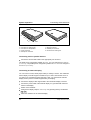
Backup disks
The backup disks contain the software stored on your hard disk, when the PC is
delivered. Please order from your sales partner.
A26391-K64-Z100-2-7619
Is there ...
... any technical problem or other
question you need clarified?
Please contact:
– one of our IT Service Shops
– your sales partner
– your sales office
You will find the addresses of the
IT Service Shops in the enclosed
warranty coupon booklet.
... anything you want to tell us
about this manual?
Please send us your comments quoting
the order number of the manual.
Siemens Nixdorf Informationssysteme AG
User Documentation Department
BS2000 OS ID 4, Otto-Hahn-Ring 6,
D-81730 München, Germany
Fax: ++49 89 / 6 36-4 04 43
Introduction
Important notes
PCD-4ND
PCD-5ND
Preparation for use
Operation
System configuration
Operating Manual
System expansion
Troubleshooting
System specifications
Index
December 1995 edition
Your training needs
...
The Siemens Nixdorf Training Centers offer you a wide range of
training courses in information technology and on IT products and
other subjects - onsite near to your workplace or offsite at one of our
training centers.
Contact us for information on consulting, course schedules and
selfstudy material.
Please write or fax:
Siemens Nixdorf Informationssysteme AG
Training Center, Beratungsservice
D-81730 München
Fax.: ++49 89 / 636-42945
DPMS and VESA are registered trademarks of Video Electronics Association
Intel and Pentium are registered trademarks and i486 SX, i486 DX2 and i486 DX4 are
trademarks of Intel Corporation, USA.
Microsoft, MS, MS-DOS and Windows are registered trademarks and Windows NT is a
trademark of Microsoft Corporation.
OS/2 and PS/2 Windows are registered trademarks of International Business Machines, Inc.
All other trademarks referenced are the trademarks or registered trademarks of their
respective owners, whose protected rights are acknowledged.
Copyright Siemens Nixdorf Informationssysteme AG 1995.
All rights, including rights of translation, reproduction by printing, copying or similar methods,
even of parts are reserved.
Offenders will be liable for damages.
All rights, including rights created by patent grant or registration of a utility model or design,
are reserved.
Delivery subject to availability; right of technical modifications reserved.
Contents
Introduction
Notational conventions
1
2
Important notes
Safety
Manufacturer's notes
Note on RFI suppression
Energy saving
Optimum battery capacity
On the move with the notebook
Class B
Important notice concerning power cord selection
For the United States and Canada
For the United Kingdom
3
3
5
5
6
6
6
7
8
8
10
Preparation for use
Unpacking and checking the notebook
Connecting the power supply unit
Installing the operating system
Creating utility disks
Installing application programs and drivers
11
11
12
13
15
15
Operation
Choosing where to set up your notebook
Switching on the notebook
Switching off the notebook
Using floppy disks
Write-protecting floppy disks
Displays and input devices
Displays
Keyboard
Key combinations
Trackball and trackball buttons
Internal microphone and internal loudspeaker
Using the power-management features
Enabling the Long Life mode
Enabling Low Power mode
Enabling Doze mode
Enabling Standby mode
Enabling Suspend mode
17
17
18
18
19
19
20
20
22
25
28
28
29
29
29
30
30
31
A26391-K64-Z100-2-7619
Contents
Switching off the display
Enabling the hard disk's power-management feature
Disabling the system speaker
Changing display settings
Setting the gray scales for the monochrome display
Switching between normal and reverse video
Switching between internal and external displays
Setting the display contrast
Setting the display brightness
Volume adjustment
Using the security features
System Lock
Keyboard Lock
Setup Lock
Restricting access to the docking unit
Preventing the notebook from booting from floppy disk
Preventing write operations to floppy disk
Preventing write operations to PCMCIA cards
Locking the serial port
Locking the parallel port
The battery
Charging the battery
Inserting and removing batteries
Deep-discharging/recharging the battery
Cleaning the notebook
Rebuilding the hard disk
Code table for the standard character set
32
32
32
33
33
33
33
34
34
34
35
35
35
36
36
36
36
37
37
37
38
38
41
45
46
47
48
System configuration
Starting the Setup program
Using the Setup program
Changing the system settings - System Setup
Display settings - Video Setup
Setting up the security features - Security Setup
Setting up the power management features Power Management Setup
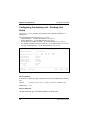
Configuring the docking unit - Docking Unit Setup
49
50
51
52
55
57
64
68
A26391-K64-Z100-2-7619
Contents
System expansion
Adding/removing memory (PCD-4ND)
Adding/removing memory (PCD-5ND)
Installing and removing PCMCIA cards
Connecting external devices
Port covers and connectors
Connecting serial or parallel devices
Connecting an external display
Connecting a mouse
Connecting an external keyboard
Connecting a docking unit or station box
Connecting external audio devices
Transferring data with the infrared interface
Changing the keycaps
71
71
74
77
80
81
82
82
83
83
84
85
85
86
Troubleshooting
The POWER LED does not light up when the notebook is switched on
The notebook's display remains blank
The notebook's display is difficult to read
The external display remains blank
The external display is blank or the image is unstable
The notebook seems to have locked up (crashed)
The trackball does not respond
The mouse does not respond
The notebook will not write to floppy disk
The battery drains quickly or becomes hot
The PC's date or time is incorrect
The printer does not print
The battery symbol is flashing
Acoustic warnings
On-screen error messages
87
87
88
89
89
90
91
91
92
92
93
93
93
94
94
95
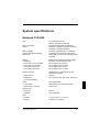
System specifications
Notebook PCD-4ND
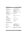
Notebook PCD-5ND
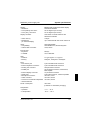
Power supply unit
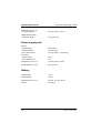
Battery
I/O addresses, interrupts and DMA channels
A26391-K64-Z100-2-7619
99
99
100
102
102
103
Contents
Pin assignment
DC input connector
Port for external keyboard and PS/2 mouse
Serial port
Port for external display
Parallel port
Keyboard layouts
Danish
French
German
Italian
Norwegian
Spanish
Swedish
Swiss
UK English
US English
104
104
104
105
106
107
108
108
108
109
109
110
110
111
111
112
112
Index
113
A26391-K64-Z100-2-7619
Introduction
This Operating Manual describes, among other things, how to set up, operate and
expand the PCD-4ND and PCD-5ND notebooks. Unless otherwise specified, the
information applies for both the PCD-4ND and the PCD-5ND.
Innovative technology and ergonomic design make this notebook the ideal userfriendly and reliable travel companion. The MS-DOS operating system, Windows
for Workgroups and Software Utilities are pre-installed on the hard disk to facilitate
the procedure when you use your notebook for the first time.
The power-management SL-enhanced processor coupled with power-management
functions (APM = Advanced Power Management) ensure effective use of the
battery life of the notebook. The battery can be simply replaced or recharged using
the optional auto adapter should it drain while you are on the move. You can use
the notebook with an additional battery. To do so, you must change the built-in
floppy disk drive against the additional battery. This will double battery life in mobile
use. To allow you to utilize the optimum capacity of the battery, you should deepdischarge and recharge it at regular intervals.
The PCD-4ND is equipped with a 4 MB main memory which can be upgraded to 8,
12 or 20 MB. The PCD-5ND is equipped with a 8 MB main memory which can be
upgraded to 16, 24 or 40 MB. Data is saved on an IDE hard disk drive. An external
disk drive can be connected to the parallel port of the notebook if you wish to work
with floppy disks. The notebook also features two PCMCIA slots for using PCMCIA
cards (types 1, 2 and 3). The drivers for PCMCIA cards are included on the
PCMCIA Utility floppy disk supplied.
Connections for external devices such as screen, printer and mouse are located on
the rear panel of the notebook. The PS/2 port recognizes the input device (e.g.
external keyboard, mouse) which has been connected. The parallel port (which
supports ECP and EPP modes) is designed to accommodate bi-directional data
transfer. In addition, the notebook has a connection port for a docking unit or a
station box. The notebook disposes of a infrared interface for wireless data
transfer.
An audio controller, a loudspeaker, a microphone and an audio connector provide
your notebook with an audio capability. You can thus incorporate voice, noise
effects and music into your PC environment. You can also connect an external
microphone and an external loudspeaker.
A26391-K64-Z100-2-7619
1
Introduction
The system settings of the notebook can be configured via the user-friendly Setup
program. Certain system settings (e.g. screen display, power-management
functions) can be modified via various key combinations while you are using the
notebook.
The notebook also features security functions to protect your data against
unauthorized access. Booting the operating system or access to the Setup program
can thus be protected by means of passwords.
For additional information on this notebook PC, refer to:
– INFO in MS Windows (utilities and drivers)
– the information files (e.g., *.DOC, *.TXT, *.WRI, *.HLP)
Notational conventions
The characters and typefaces used in this manual have the following meaning:
!
Pay particular attention to texts marked with this symbol. Failure to observe
this warning endangers your life, destroys the system, or may lead to loss of
data.
i
describes additional information, hints and tips.
indicates an operational step which you should carry out.
indicates that you must enter a blank.
↵ indicates that you must press the Enter key after the characters you have
entered.
Text in a typewriter font represents screen output.
Text in a bold typewriter font has to be typed at the keyboard.
Text in italics denotes commands or menu options.
"Quotation marks" indicate special emphasis and chapter names.
2
A26391-K64-Z100-2-7619
Important notes
In this chapter you will find information regarding safety which it is essential to take
note of with your notebook. The chapter also contains information on the licenses
issued for your notebook.
Safety
This device complies with the relevant safety regulations for data processing
equipment, including electronic office machines for use in an office environment. If
you have any questions, contact your sales office or our customer service.
– Always use the bag supplied when transporting the notebook.
If it needs to be shipped, use the original packaging or other suitable packaging
to protect it from damage through mishandling.
– If the device is brought into the installation site from a cold environment,
condensation can form. Before operating the device, wait until it is absolutely
dry and has reached approximately the same temperature as the installation
site.
– Read the information on environmental conditions before setting up and using
the notebook (see the sections "Preparation for use" and "System
specifications").
– Only run the notebook off the battery or power supply unit included, or off
authorized accessories (car adapter, docking unit or station box).
– The power supply unit has a specially approved power cable and must only be
connected to a grounded wall outlet. If the power adapter is connected to the
grounded wall outlet, it must be free-standing. The power adapter may not be
covered while it is in operation. Do not stand it on heat-sensitive material.
– Ensure that the power socket on the power supply unit or the grounded wall
outlet is freely accessible.
– The power switch does not disconnect the device from the line voltage. To do
this, you must pull out the power plug.
– Lay all cables so that nobody can stand on them or trip over them. When
attaching the PC, observe the relevant notes in the chapter "System expansion".
– No data transmission cable should be connected or disconnected during a
thunderstorm.
A26391-K64-Z100-2-7619
3
Important notes
– Please ensure that no objects (e.g., necklaces, paperclips etc.) or liquids can
get into the interior of the device (electrical shock, short circuit).
– In emergencies (e.g. damaged casing, elements or cables, penetration of liquids
or foreign matter), switch off the notebook immediately, remove the power
connector, remove the battery, and contact your sales office or customer
service.
– Only qualified technicians may repair the device. Unauthorized opening or
incorrect repair may greatly endanger the user (electric shock, fire risk).
– When cleaning the system unit, observe the relevant notes in the chapter
"Operation".
– Install only system expansions that satisfy the requirements and rules governing
safety and electromagnetic compatibility and relating to telecommunications
terminal equipment. If you install other expansions, you may damage the
system or violate the safety regulations and regulations governing RFI
suppression. Information on which system expansions are suitable can be
obtained from the customer service or your sales office.
– You may use the battery only for this PC.
Take care not to drop the battery or otherwise damage its housing (risk of fire).
If the battery fails, do not use it in the notebook.
Never interconnect the positive and negative terminals of the battery.
Used batteries must be disposed of in accordance with local regulations (special
refuse).
– If the LCD display is damaged (e.g. glass broken), do not allow any escaping
liquid to come into contact with skin, mucous membranes (eyes, mouth). Do not
inhale vapors.
Clean parts of the body and clothing that have already come into contact with
such liquids with plenty of water and soap.
– The warranty expires if the notebook is damaged during the installation or
replacement of system expansions.
– You may set only those resolutions and refresh rates specified in the chapter
"System specifications" or in the operating manual of the monitor description.
Otherwise you may damage your monitor. If you are in any doubt, contact your
sales office or customer service.
– The notebook includes a lithium battery which may be replaced only by
authorized personnel. Incorrect handling may lead to a risk of explosion.
The lithium battery may be replaced only with an identical battery or with a type
recommended by the manufacturer. The battery must be disposed of in
accordance with local regulations concerning special waste.
4
A26391-K64-Z100-2-7619
Important notes
For Denmark
ADVARSEL
Lithiumbatteri - Eksplosionsfare ved fejlagtig håndtering. Udskiftning må kun
ske med batteri af samme fabrikat og type. Lever det brugte batteri tilbage til
leverandøren.
For Norway
ADVARSEL
Eksplosjonsfare ved feilaktig skifte av batteri. Benytt samme batteritype eller en
tilsvarende type anbefalt av apparatfabrikanten. Brukte batterier kasseres i
henhold til fabrikantens instruksjoner.
For Sweden
VARNING
Eksplosionsfara vid felaktigt batteribyte. Använd samma batterityp eller en
ekvivalent typ som rekommenderas av apparattillverkarenfabrikanten. Kassera
använt batteri enligt fabrikantens instruktion.
For Finland
VAROITUS
Paristo voi räjähtää, jos se on virheellisesti asennettu. Vaihda paristo
ainoastaan laitevalmistajan suosittelemaan tyyppiin. Hävitä käytetty paristo
valmistajan ohjeiden mukaisesti.
Manufacturer's notes
If there is a CE symbol on the device, then:
The device complies with the requirements of the EEC directive
89/336/EEC with regard to "Electromagnetic compatibility".
Note on RFI suppression
All other devices connected to this product must have RFI suppression in
accordance with EC directive 89/336/EEC. Products meeting these requirements
are accompanied by a certificate issued by the manufacturer and carry the
CE symbol.
A26391-K64-Z100-2-7619
5
Important notes
Energy saving
Make use of the notebook's power management features (see "Operation").
The notebook uses less power when the power management features are enabled.
You will then be able to work for longer before having to recharge the battery.
Optimum battery capacity
To allow you to utilize the optimum capacity of the battery, you should deepdischarge and recharge it at regular intervals (see the chapter entitled "Operation Deep-discharging/recharging the battery)
On the move with the notebook
Please observe the points listed below when transporting your notebook PC.
Transporting the notebook
– Do not carry the notebook by its open screen or by its battery compartment if
the battery is removed.
– Switch the notebook off and close the LCD display and the covers for the ports
and the PCMCIA cards.
– Use the bag supplied to transport the notebook.
If it needs to be shipped, use the original packaging or other suitable packaging
to protect it from damage through mishandling.
– Protect the notebook from severe shocks and extreme temperatures (e.g., direct
sunlight in a car).
Before starting the journey
– Copy important data from the hard disk to a floppy disk.
– If you wish to use your notebook during a flight, check first with the flight
attendants if it is permissible to do so.
– If you are travelling abroad, ensure that the power supply unit can be operated
on the local mains voltage. If this is not the case, obtain the appropriate power
supply unit for your notebook.
Do not use any other voltage transformers!
6
A26391-K64-Z100-2-7619
Important notes
Class B
The following statement applies to the products covered in this manual, unless
otherwise specified herein. The statement for other products will appear in the
accompanying documentation.
NOTE:
This equipment has been tested and found to comply with the limits for a "Class B"
digital device, pursuant to Part 15 of the FCC rules. These limits are designed to
provide reasonable protection against harmful interference in a residential
installation. This equipment generates, uses and can radiate radio frequency
energy and, if not installed and used in strict accordance with the instructions, may
cause harmful interference to radio communications. However, there is no
guarantee that interference will not occur in a particular installation. If this
equipment does cause harmful interference to radio or television reception, which
can be determined by turning the equipment off and on, the user is encouraged to
try to correct the interference by one or more of the following measures:
– Reorient or relocate the receiving antenna.
– Increase the separation between equipment and the receiver.
– Connect the equipment into an outlet on a circuit different from that to which the
receiver is connected.
– Consult the dealer or an experienced radio/TV technician for help.
Siemens Nixdorf Informationssysteme AG is not responsible for any radio or
television interference caused by unauthorized modifications of this equipment or
the substitution or attachment of connecting cables and equipment other than
those specified by Siemens Nixdorf Informationssysteme AG. The correction of
interferences caused by such unauthorized modification, substitution or attachment
will be responsibility of the user.
The use of shielded I/O cables is required when connecting this equipment to any
and all optional peripheral or host devices. Failure to do so may violate FCC rules.
This digital apparatus does not exceed the Class B limits for radio noise emissions
from digital apparatus as set out in the interference-causing equipment standard
entitled "Digital Apparatus", ICES-003 of the Canadian Department of
Communications.
Cet appareil numérique respecte les limites de bruits radioélectriques applicables
aux appareils numériques de Classe B prescrites dans la norme sur le matériel
brouilleur: "Appareils Numériques", NMB-003 édicté par le ministre des
Communications du Canada.
A26391-K64-Z100-2-7619
7
Important notes
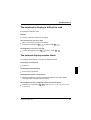
Important notice concerning power cord
selection
The power cord for this unit has been packed separately and has been selected
according to the country of destination. It must be used to prevent electric shock.
Use the following guidelines if it is necessary to replace the original cord set.
The female receptacle of the cord set
must meet CEE-22 requirements (see
Figure 1).
For the United States and Canada
Use a UL listed and CSA labelled cord set consisting of a three conductor cord with
a maximum length of 15 feet.
For units which stand on a desk or table, type SVT or SJT cord sets shall be used.
For units which stand on floor, only SJT type cord sets shall be used.
The cord set must be selected according to the current rating for your unit. Please
consult Table A for the selection criteria for power cords used in the United States
and Canada.
8
A26391-K64-Z100-2-7619
Important notes
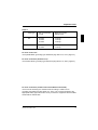
Table A:
Cord Type
Size of Conductors
in Cord
Maximum Current
Rating of Unit
SJT
18 AWG
16 AWG
14 AWG
10 Amps
12 Amps
12 Amps
SVT
18 AWG
17 AWG
10 Amps
12 Amps
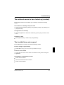
For units set at 115 V:
use a parallel blade, grounding type attachment plug rated 15 A, 125 V (Figure 2).
For units set at 230 V (domestic use):
use a tandem blade, grounding type attachment plug rated 15 A, 250 V (Figure 3).
For units set at 230 V (outside of the United States and Canada):
use a cord set consisting of a minimum AWG according to Table A and a
grounding type attachment plug rated 15 A, 250 V. The cord set should have the
appropriate safety approvals for the country in which the equipment will be installed
and should be marked HAR.
A26391-K64-Z100-2-7619
9
Important notes
For the United Kingdom
Should the plug on the flexible cord not be of the type for your socket outlets, do
not use an adapter but remove the plug from the cord and discard. Carefully
prepare the end of the supply cord and fit a suitable plug.
WARNING
THIS APPLIANCE MUST BE EARTHED
IMPORTANT
The wires in this mains lead are coloured in accordance with the following code:
Green and Yellow:
Earth
Blue:
Neutral
Brown:
Live
As the colours of the wires in the mains lead of this appliance may not correspond
with the coloured markings identifying the terminals in your plug, proceed as
follows:
– The wire which is coloured Green and Yellow must be connected to the terminal
in the plug which is marked with the letter E or by the earth symbol or coloured
Green or Green and Yellow.
– The wire which is coloured Blue must be connected to the terminal which is
marked with the letter N or coloured Black.
– The wire which is coloured Brown must be connected to the terminal which is
marked with the letter L or coloured Red.
10
A26391-K64-Z100-2-7619
Preparation for use
!
Pay attention to the information provided in "Important notes" in the
previous chapter.
You must install and charge the battery and install the operating system,
application programs and drivers before you can work with the notebook.
Refer to the chapter on "System expansions" for instructions on how to connect
external devices (e.g. mouse, printer, disk drive) to the notebook.
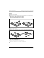
Unpacking and checking the notebook
Unpack all the parts.
Check the contents of the shipment for visible damage incurred during
transportation.
Check that the shipment matches up with the delivery note.
Check whether all the necessary details have been entered on the first page of
the guaranty booklet or on the guaranty card.
If you discover damage or notice discrepancies between the delivery papers and
the contents of the shipment, please contact your sales office.
!
We recommend that you keep the original packaging in case you need to
ship the equipment again.
A26391-K64-Z100-2-7619
11
Preparation for use
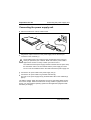
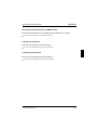
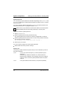
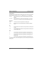
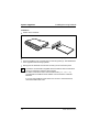
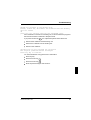
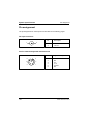
Connecting the power supply unit
Connecting the power supply unit
Place the notebook on a level, stable surface.
3
a
1
b
2
Plug the DC output connector on the power supply unit into the DC input
connector on the notebook (1).
!
The supplied power cord conforms to the requirements of the country in
which you purchased your notebook. Make sure that the power cable is
approved for use in the country in which you intend to use it.
The notebook and the power supply should be at least 200 mm apart. Keep
the area within 100 mm of the notebook and the power supply unit clear.
Do not cover the ventilation slots in the notebook and the power supply unit.
Connect the AC power cable to the power supply unit (2).
Connect the AC power cable to a grounded wall outlet (3).
The LED on the power supply unit (b) and BATTERY LED on the notebook (a)
light up.
The battery charges. When the notebook is not running, the battery takes roughly
two hours to charge. When the notebook is running, it takes roughly five hours to
charge. You can install the operating system and the application programs while
the battery is charging.
12
A26391-K64-Z100-2-7619
Installing the operating system
Preparation for use
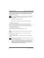
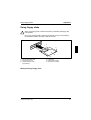
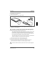
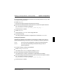
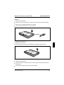
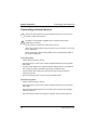
Installing the operating system
1
b
2
a
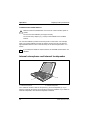
a = Power switch
b = Trackball
Slide forward the release tabs (1) and swing open the cover (2).
When you install software you have to work with floppy disks, the keyboard
and the trackball. If you are unfamiliar with using floppy disks or input
devices, see "Using floppy disks" and "Displays and input devices" in the
"Operation" section.
i
!
You must not power-cycle or warm-boot your notebook during first-time
installation .
Press the power switch for roughly one second.
Wait until a choice of different languages is displayed on screen.
Select the language to be used for the installation procedure by pressing the
appropriate function key (e.g. press the F2 function key for language 2).
Select the language in which the operating system is to be installed by pressing
the appropriate function key.
Once the correct language is displayed, press the Enter key.
Note that your choice of language is final and cannot be reversed.
A26391-K64-Z100-2-7619
13
Preparation for use
Installing the operating system
The operating system is installed. Once it has finished installing, the start-up
program appears on screen. You can use the trackball and/or the keyboard to
operate the start-up program.
If a choice of different language-specific keyboard layouts is displayed on
screen, you can select either the default keyboard layout or one of the
others indicated.
i
Confirm the default keyboard layout.
Or
Choose one of the other country-specific keyboard layouts listed.
The registration screen appears.
Fill in the relevant fields to register as the user of the installed software.
Once you have finished registration, the system asks if you would like to run
through a Microsoft Windows tutorial. Once you have finished the tutorial, you
return to the start-up program.
Continue with the start-up program.
A number of different menu options are displayed on screen.
!
On-line help is available; to access it, select the information menu item.
Select all the menu items shown on screen in the sequence indicated.
Quit the start-up program.
You can now begin to work with your notebook or continue to install additional
software.
i
Follow the instructions in the manuals and information files concerning the
application programs and drivers.
Once you have installed the operating system, the application programs and
drivers, and have generally familiarized yourself with the notebook, you
should deep-discharge and recharge the battery. Deep-discharging and
recharging the battery ensures that you obtain optimum capacity. How to
proceed is described in the section "The battery".
14
A26391-K64-Z100-2-7619
Utility disks, programs
Preparation for use
Creating utility disks
To create the utility disks you need two unformatted 3 1/2-inch floppy disks.
Switch on the notebook.
Start Microsoft Windows.
Choose the Utility disks icon and press the Enter key.
Follow the on-screen instructions.
Label the floppy disks as shown in the on-screen instructions.
Installing application programs and drivers
Follow the instructions provided in the manuals and the information files (e.g.,
INFO, README, *.HLP, *.DOC, *.TXT or *.WRI) supplied with your application
programs and device drivers.
A26391-K64-Z100-2-7619
15
Operation
When used away from a wall power outlet, the notebook runs on its built-in battery.
You can increase battery life by enabling its power management features.
If you use the notebook in a normal office situation, you run it off the mains with the
aid of the power supply unit, or in a docking unit or station box. This conserves
battery power for mobile use.
Choosing where to set up your notebook
Select a suitable place at which to set up your notebook. We recommend the
following:
– Choose a stable, non-slip surface on which to set up the notebook. Set it up with
care: the notebook's plastic feet might conceivably scratch or damage the finish
on different types of furniture.
– Do not use the notebook in environments with high dust, humidity or heat levels.
– Keep other objects 100 mm clear of the notebook and its power supply unit to
ensure adequate ventilation. The space between the notebook's plastic feet
must be clear. Do not place it on a soft surface (e.g., a carpet or soft
furnishings). Do not cover the ventilation slots in the notebook and the power
supply unit.
– The power supply unit must be at least 200 mm away from the notebook. It must
be free-standing and may not be covered. Do not stand the power adapter on
heat-sensitive material.
– For wireless data transfer you must align the notebook's infrared interface with
that of the partner device (e.g. PC).
The devices must not be more than one meter apart.
A26391-K64-Z100-2-7619
17
Operation
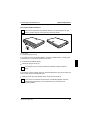
Switching the notebook on/off
Switching on the notebook
1
3
2
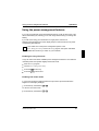
Slide forward the release tabs (1) and swing open the cover (2).
Press the power switch (3) for roughly one second.
Switching off the notebook
2
3
1
3
Press the power switch (1) for roughly one second.
Close the cover of the notebook (2) so that it locks into place on the left and
right (3).
18
A26391-K64-Z100-2-7619
Using floppy disks
Operation
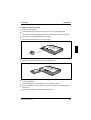
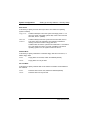
Using floppy disks
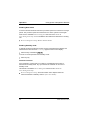
!
When using floppy disks, read the information provided by the floppy-disk
manufacturer.
Do not use cleaning disks in the floppy disk drive. Doing so would destroy
the read/write heads in the drive in just 20 seconds.
1
2
3
6
4
5
1 = Slot for read/write head
2 = Head access cover
3 = HD disk indicator hole
(high density)
4 = Label area
5 = Write-protect slider
6 = Direction of insertion
Write-protecting floppy disks
A26391-K64-Z100-2-7619
19
Operation
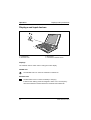
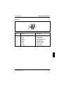
Displays and input devices
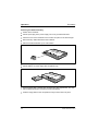
Displays and input devices
1 2
3
4
1 = POWER LED
2 = BATTERY LED
3 = Display field
4 = Trackball and trackball buttons
Displays
The notebook has two LEDs and an LCD-type function display.
POWER LED
The POWER LED is on when the notebook is switched on.
BATTERY LED
The BATTERY LED is on when the battery is charging.
It flashes when battery power has dropped to below 10%. The frequency
with which it flashes increases before the notebook shuts itself down.
20
A26391-K64-Z100-2-7619
Displays and input devices
Operation
Function display
1
2
Turbo
CapsLK
NumLK
Standby
ScrLK
PadLK
Symbols and texts in the function display show the actual state of the notebook.
The meaning of the symbols and texts are as follows:.
1
2
The battery symbol shows the amount of power left in the built-in battery.
A 1 indicates that the information applies to the battery in the battery
compartment.
A 2 indicates that the information applies to the additional battery.
The arrow indicates that the battery is charging.
This symbol indicates that the battery is 90%-100% charged.
This symbol indicates that the battery is 50%-90% charged.
This symbol indicates that the battery is 10%-50% charged.
This symbol indicates that the battery is less than 10% charged.
If it has a flashing border, the battery is empty (if the BATTERY LED is
flashing, or there is no battery installed (if the BATTERY LED is off).
Flashing segments indicate that the notebook has detected that its battery is
defective.
This indicates that the notebook is connected to an external power source
(e.g., the power supply unit).
This indicates that the notebook's hard disk is currently being accessed.
This indicates that the floppy disk in the floppy disk drive is being accessed.
You must not remove the floppy disk when this symbol is visible.
A26391-K64-Z100-2-7619
21
Operation
Displays and input devices
Turbo
This indicates that notebook's CPU is operating at its maximum
clock rate (speed).
Standby
This indicates that the notebook is in Standby mode.
CapsLK
This indicates that all the characters you type will appear as
uppercase. In the case of keys marked with a number of
characters, the upper-left character will appear. The CapsLK
indicator appears when you press the Caps Lock key.
ScrLK
This appears when you press the Scroll Lock key. The effect this
key has varies from program to program.
NumLK
This appears when you press the Pad Num key. If PadLK is visible
in the function display, the blue numbers on the lower right on keys
in the integrated numeric keypad are enabled.
PadLK
This appears when you press the Fn + Pad Num keys. This
enables the blue editing functions on the upper right on keys in the
integrated numeric keypad.
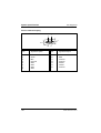
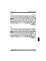
Keyboard
The following description of key functions applies to systems running the MS-DOS
operating system. Additional functions supported by the keys are described in the
relevant manuals supplied with your application programs.
22
A26391-K64-Z100-2-7619
Displays and input devices
Operation
The figure below shows how to access the different characters and editing
functions on keys with overlaid functions. The keystrokes shown in the example
only work if CapsLK, NumLK, and PadLK have not been enabled (i.e., they are not
visible in the function display).
Backspace
The Backspace key deletes the character to the left of the cursor.
Tab key
The Tab key moves the cursor to the next tab stop.
Enter key (also, Return or Carriage Return)
The Enter key tells the computer that the command line entered is
complete. The command you have entered is executed when you
press Enter.
Caps Lock
The Caps Lock key shifts the alphabetic characters on the
keyboard to uppercase. (When it is enabled, the CapsLK symbol
appears in the function display.) In the case of overlay keys, the
character on the upper left on the keycap appears when that key is
pressed. To cancel the Caps Lock function, simply press the Caps
Lock key again.
Shift
The Shift key causes uppercase characters to appear. In the case
of overlay keys, the character on the upper left on the keycap
appears when that key is pressed.
A26391-K64-Z100-2-7619
23
Operation
Alt Gr
Fn
Fn
+ Fn
Displays and input devices
Alt Gr
The Alt Gr key causes the characters in the lower middle of the
keycap to appear (e.g., { in the case of the 7 key).
Fn
The Fn key enables the special functions indicated in blue on
overlay keys (see "Key combinations").
If the external keyboard does not feature an Fn key, you can
simultaneously press the Alt and Shift keys instead.
Cursor keys
The cursor keys move the cursor in the direction of the arrow, i.e.,
up, down, left, or right.
Pad Num
When the numeric keypad is enabled (PadLK is visible in the
function display), the Pad Num key causes this set of keys to
produce numbers (NumLK appears in the function display).
Pressing them produces the blue characters shown on the bottom
right on the keycaps.
Pause
The Pause key temporarily suspends display output. Output will
resume when press any other key.
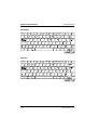
Integrated numeric keypad
1 = Characters enabled when neither NumLK, nor PadLK are visible in the function display
2 = Editing functions enabled when PadLK is visible in the function display
3 = Characters enabled when NumLK and PadLK are visible in the function display.
The key combination Fn + Pad Num enables and disables the integrated numeric
keypad. If it is enabled, PadLK is visible in the function display. The keys in the
integrated numeric keypad then perform the editing functions indicated in blue on
the upper right of the keycaps.
24
A26391-K64-Z100-2-7619
Displays and input devices
Operation
If PadLK is visible in the function display, pressing the Pad Num key enables and
disables the numeric functions of the keys in the integrated numeric keypad. The
keys produce numbers (the numbers indicated in blue on the lower right of the
keycaps) when NumLK is visible in the function display.
If PadLK and/or NumLK are visible in the function display, the keys in the integrated
numeric keypad will also produce the standard characters shown on the keys. If
you press and hold the Fn key, the keys will produce lowercase letters and
numbers.
If you press and hold the key combination Fn + Shift, the keys will produce
uppercase letters and the characters indicated on the upper left of the keycaps.
Key combinations
The description of key combinations that follows applies to systems running the
MS-DOS operating system. Other key combinations are described in the relevant
manuals supplied with your application programs.
You enter key combinations as follows:
Press and hold the first key in the combination.
While keeping the first key pressed, press the other key or keys in the
combination.
If the external keyboard does not feature an Fn key, you can
simultaneously press the Alt and Shift keys instead.
i
Fn
Fn
+ Fn
Fn
Fn
+ Fn
Fn
Fn
+ Fn
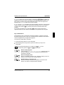
ESC
SETUP
F1
LCD Off
F2
Low
Power
Start the Setup program
If the message Press Fn + Esc for Setup appears when you
start your notebook, run the Setup program by pressing the key
combination indicated.
Switch the display on/off
This key combination switches your notebook's display on and off.
Doing so does not affect any running programs.
Enable/disable Low Power mode
This key combination enables and disables Low Power mode
(slower CPU speed, half-bright display backlight).
A26391-K64-Z100-2-7619
25
Operation
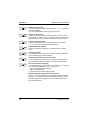
Fn
Fn
+ Fn
Fn
Fn
+ Fn
Fn
Fn
+ Fn
Fn
Fn
+ Fn
Fn
Fn
+ Fn
Fn
Fn
+ Fn
Fn
Fn
+ Fn
F3
Standby
F4
Suspend
F6
Load
Password
F8
Speaker
On/Off
F10
Grey
Scale
F11
Reverse
Video
F12
LCD/CRT
Displays and input devices
Enable Standby mode
This key combination enables Standby mode. Standby appears in
the function display.
You can cancel Standby mode by pressing any key.
Enable Suspend mode
This key combination enables Suspend mode. When you switch
the notebook on again, it returns to the same place you were in the
program that was running when you switched to Suspend mode.
Load the setup password
This key combination loads the setup password from the disk
System Utilities (see "Starting the setup program").
Enable/disable the speaker
This key combination switches the notebook's built-in speaker
on/off.
Set up gray scales
If your notebook has a monochrome display, this key combination
lets you alter the gray scales it displays.
Switch between normal and reverse video
If your notebook has a monochrome or DSTN color display, this
key combination switches it between normal and reverse video.
Select internal/external display
If an external display is connected to your notebook, you can switch
to it with this key combination. You can opt to use:
– just the notebook's internal display
– just the external display
– both the internal and the external display.
Enable/disable the integrated numeric keypad
This key combination enables and disables the integrated numeric
keypad. PadLK appears in the function display when the numeric
keypad is enabled. The editing functions indicated in blue on the
keycaps are enabled.
26
A26391-K64-Z100-2-7619
Displays and input devices
Operation
Keyboard lock
If you set Keyboard Lock to Enable in the Setup program, this key
combination locks the keyboard, the trackball and, if connected, an
external PS/2 mouse; it also switches off the display. This does not
affect any programs that are running.
To cancel the keyboard lock, enter the system password.
Reduce the display contrast
If your notebook has a monochrome or DSTN color display, this
key combination reduces its contrast.
Fn
Fn
+ Fn
Increase the display contrast
If your notebook has a monochrome or DSTN color display, this
key combination increases its contrast.
Fn
Fn
+ Fn
Increase the display brightness
This key combination increases the brightness of the display.
Fn
Fn
+ Fn
Reduce the display brightness
This key combination increases the brightness of the display.
Fn
Fn
+ Fn
Halt the current operation
This key combination can be used to halt an operation instantly (its
effect depends on the program that is running).
Strg
C
Halt the current operation
This key combination can be used to halt an operation instantly
without clearing the keyboard buffer.
Warm boot
This key combination triggers a reset and warm-boots the
notebook.
Backtab (Shift+Tab)
This key combination moves the cursor back to the
previous tabular stop.
A26391-K64-Z100-2-7619
27
Operation
Displays and input devices
Trackball and trackball buttons
!
Make sure that the trackball does not come into contact with dirt, liquids or
grease.
Do not touch the trackball if your fingers are dirty.
Do not rest heavy objects (e.g., books) on the trackball or the trackball
buttons.
You use the trackball to position the mouse pointer on the screen. For example,
when you roll the trackball to the left, the pointer moves to the left. The left and
right trackball buttons function in the same way as the left and right buttons on a
mouse.
i
If you attach and install an external mouse, the trackball and its buttons are
disabled.
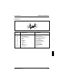
Internal microphone and internal loudspeaker
2
1
1 = internal microphone
2 = internal loudspeaker
Your notebook contains a built-in microphone (1) and a loudspeaker (2). If you
attach an external microphone, the internal microphone is disabled. If you attach an
external loudspeaker, the internal loudspeaker is disabled.
28
A26391-K64-Z100-2-7619
Using power-management features
Operation
Using the power-management features
If you use the notebook's power-management features, it will use less power. This
will increase battery life, allowing you to work longer before having to recharge the
battery.
If you will not be using your notebook for a longer period, switch it off.
Reducing the brightness level of the display helps to reduce the amount of power
consumed by the notebook.
i
If you enable one of the power-management options in the
Power Management Setup menu in the Setup program, that option will still be
enabled the next time you switch on your notebook.
Enabling the Long Life mode
Long Life mode uses all the available power-management features. The notebook
uses little power and operates slightly slower than usual.
Start the Setup program.
Choose Power Management Setup.
Press the F4 function key.
Press the F10 function twice.
Enabling Low Power mode
In Low Power mode the notebook reduces its processor speed and halves the
brightness of its display backlight.
Press the key combination Fn + F2 .
To cancel Low Power mode:
Press the key combination Fn + F2 .
A26391-K64-Z100-2-7619
29
Operation
Using power-management features
Enabling Doze mode
In Doze mode the notebook reduces its processor speed if it is inactive for a longer
period. The processor speed is increased as soon as the system is used again.
Doze mode is available if Power Management has been set to Enable in
Power Management Setup. It is not available if the notebook is attached to a docking
unit.
In Power Management Setup, set Doze Mode to Enable.
Enabling Standby mode
In Standby mode the notebook's system clock is suspended and its display and
hard-disk motor are shut down. Standby appears in the function display.
Press the key combination Fn + F3 .
To revert to normal operation from Standby mode:
Press any key.
Automatic activation
If the notebook is running and is not used for a predefined period of time, it
switches into Standby mode. Any input causes the notebook to come out of
Standby mode.
This feature is available if Power Management has been set to Enable in
Power Management Setup.
In Power Management Setup, set the time which has to elapse before the
notebook switches to Standby mode in System Auto Standby.
30
A26391-K64-Z100-2-7619
Using power-management features
Operation
Enabling Suspend mode
In Suspend mode all the active data (active programs and files) is saved to the
hard disk and the notebook is switched off. The active data can only be saved if
sufficient space is available on the hard disk (at least the main memory size +
2 Mbytes).
If you are running the operating system OS/2 or Windows NT, you have to set up
an additional FAT partition on the hard disk (see the manuals supplied with the
operating system in question). The FAT partition must be at least the size of 16
Mbyte.
You cannot use Suspend mode if the notebook is connected to a docking unit or if
the space available on the hard disk is not sufficient.
!
If your notebook is in Suspend mode:
– do not connect any external peripheral devices
– do not disconnect any external peripheral devices
– do not attempt to switch it on if the built-in battery is empty
– do not change the configuration with the Setup program
– do not change or remove the floppy disk, if inserted
– do not add or remove RAM
– do not add or remove any PCMCIA cards.
Press the key combination Fn + F4 .
To revive the notebook from Suspend mode:
Switch the notebook on.
The notebook reverts to the status it had prior to switching into Suspend mode.
Automatic activation
If the notebook is not used for the predefined period of time, it switches from
Standby mode to Suspend mode.
This feature is available if Power Management has been set to Enable in
Power Management Setup and you have specified a time in System Auto Standby.
In Power Management Setup, set the time which has to elapse before the
notebook switches to Suspend mode in System Auto Suspend.
A26391-K64-Z100-2-7619
31
Operation
Using power-management features
Switching off the display
Switching off the display does not affect running programs.
Press the key combination Fn + F1 .
To switch the notebook's display on again:
Press the key combination Fn + F1 .
Automatic powerdown
You set this function up in the Setup program.
If the notebook receives no input for a predefined period of time, the displays
switches off automatically. It switches on again automatically as soon as the
notebook receives input.
In Power Management Setup, set the time which has to elapse before the display
switches off in LCD Powerdown.
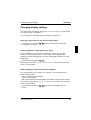
Enabling the hard disk's power-management feature
If the hard disk is not accessed for a predefined period of time, its motor switches
off automatically. It switches on again automatically the next time the hard disk is
accessed.
Set the time which has to elapse before the hard-disk motor switches off in
Hard Disk Powerdown.
Disabling the system speaker
Press the key combination Fn + F8 .
To re-enable the system speaker:
Press the key combination Fn + F8 .
You can also disable the speaker in the Setup program.
In Power Management Setup, set System Speaker to Disable.
32
A26391-K64-Z100-2-7619
Changing display settings
Operation
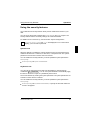
Changing display settings
You configure the basic display settings with Video Setup in the Setup program (see
the section "System configuration").
You can change the settings listed below using key combinations.
Setting the gray scales for the monochrome display
Press the key combination Fn + F10 until you have found the gray-scale
configuration you require.
Switching between normal and reverse video
If your notebook has a monochrome or DSTN color display, you can switch
between normal and reverse video. You can select a normal display (dark
characters on a light background) or a reverse display (light characters on a dark
background).
Press the key combination Fn + F11 .
The setting you select with Reverse Video in Video Setup is always active when you
switch on your notebook.
Switching between internal and external displays
If an external display is connected to your notebook, you can switch between
different display options:
– just the notebook's internal display
– just the external display
– both the internal and the external display (not possible with DSTN color display).
The setting you select with Display Device in Video Setup is always active when you
switch on your notebook.
Press the key combination Fn + F12 until you find the display option you
require.
A26391-K64-Z100-2-7619
33
Operation
Changing display settings
Setting the display contrast
If your notebook has a monochrome or DSTN color display, you can set the display
contrast.
Increasing the contrast
Press the key combination Fn + ← until you find the right display contrast.
Reducing the display contrast
Press the key combination Fn + → until you find the right display contrast.
Setting the display brightness
If you find the display too bright or too dark, you can adjust the brightness.
Increasing the brightness
Press the key combination Fn + ↑ until you find the right brightness level.
Reducing the brightness
Reducing the brightness also reduces the notebook's power consumption.
Press the key combination Fn + ↓ until you find the right brightness level.
Volume adjustment
You can adjust the volume of the loudspeaker in the audio program (e.g. mixer) or
in the application program using the audio functions.
34
A26391-K64-Z100-2-7619
Using the security features
Operation
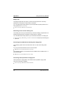
Using the security features
Your notebook has security features which prevent unauthorized access to your
data.
You can set up the security features with Security Setup in the Setup program. The
security features and the necessary settings are summarized below.
For details of how to set them up, see the section "System configuration".
i
If CapsLK, NumLK, PadLK and ScrLK are displayed in turn in the function
display, you must enter a password.
System Lock
When this feature is enabled, the system password has to be entered before the
notebook will start from a cold boot, a warm boot, or Suspend mode. The system
password is not echoed on screen when it is entered.
You can enable this security feature if you have specified a system password in
Security Setup.
In Security Setup, set System Lock to Enable.
Keyboard Lock
You can lock the input devices and switch off the display by pressing the key
combination Fn + Scroll Lock . You can set up the notebook to automatically apply
this lock if it receives no input for a predefined period of time.
The lock is released by entering the system password. The system password is not
echoed on screen when it is entered.
You can enable this security feature if you have specified a system password in
Security Setup.
In Security Setup, set Keyboard Lock to Enable, or specify the time after which the
lock is to be applied.
A26391-K64-Z100-2-7619
35
Operation
Using the security features
Setup Lock
The Setup program will only start if you enter the setup password. The setup
password is not echoed on screen when it is entered.
You can enable this security feature if you have specified a system password or a
setup password in Security Setup.
In Security Setup, set Setup Lock to Enable.
Restricting access to the docking unit
The docking unit can only be accessed if you enter the docking unit password. The
docking unit password is not echoed on screen when it is entered.
You can enable this security feature if your notebook is attached to a docking unit.
In Security Setup, set Docking Unit Password to Enable and specify the docking unit
password.
Preventing the notebook from booting from floppy disk
The operating system cannot be started from drive A: with a boot disk (system
disk).
If you only want the notebook to boot from its hard disk:
Set Boot Device to Hard Disk in Security Setup.
If the operating system is to be started from the PCMCIA card in PCMCIA slot 1 or
from the hard disk:
Set Boot Device to PCMCIA in Security Setup.
Preventing write operations to floppy disk
Write operations to floppy disks in the notebook are impossible. Floppy disks
cannot be overwritten or deleted.
In Security Setup, set Diskette Write to Disable.
36
A26391-K64-Z100-2-7619
Using the security features
Operation
Preventing write operations to PCMCIA cards
Data cannot be transferred to any PCMCIA cards installed in the notebook.
In Security Setup, set PC Card Write to Disable.
Locking the serial port
Data cannot be transferred via the serial port.
In Security Setup, set Serial Interface to Disable.
Locking the parallel port
Data cannot be transferred via the parallel port.
In Security Setup, set Parallel Interface to Disable.
A26391-K64-Z100-2-7619
37
Operation
The battery
The battery
The notebook is fitted with a nickel metal hydride battery that provides it with power
during mobile use. You can increase battery life by enabling the notebook's powermanagement features.
You can use the notebook with an additional battery. To do so, you must change
the built-in floppy disk drive against the additional battery. This will double battery
life in mobile use.
The battery charge is indicated by the BATTERY LED and the battery symbol in
the function display (see the section "Displays and input devices"). When you
switch on the notebook, it takes a few seconds before the battery status is
displayed.
The battery will last for roughly 500 charge/discharge cycles.
i
Deep-discharge and recharge the battery at regular intervals to utilize the
optimum capacity of the battery (see "Deep-discharging the battery").
Charging the battery
Only charge the battery when the ambient temperatures is between 5 ˚C and
35 ˚C.
When the notebook is not in use, the battery will charge in roughly two hours. If the
notebook is switched on, it will trickle-charge in roughly five hours. If the notebook
is fitted with two batteries, charging will take twice as long.
You can charge the battery by:
– connecting the notebook to the power supply unit
– connecting the notebook to the auto adapter
– connecting the notebook to a docking unit
– connecting the notebook to a station box
38
A26391-K64-Z100-2-7619
The battery
Operation
Connecting the power supply unit
Switch off the notebook.
Place the notebook on a level, stable surface.
3
a
1
b
2
Plug the DC output connector on the power supply unit into the DC input
connector on the notebook (1).
!
The power cord conforms to the requirements of the country in which you
purchased your notebook. Make sure that the power cable is approved for
use in the country in which you intend to use it.
The notebook and the power supply should be at least 200 mm apart. Keep
the area within 100 mm of the notebook and the power supply unit clear.
Do not cover the ventilation slots in the notebook and the power supply unit.
Do not stand the power adapter on heat-sensitive material.
The power supply unit's AC cord may only be connected to a grounded wall
outlet if the notebook is connected to the power supply unit.
Connect the AC power cord to the power supply unit (2).
Connect the AC power cord to a grounded wall outlet (3).
The LED on the power supply unit goes on (b). A few seconds later, the
notebook's BATTERY LED lights up. The battery begins to charge.
!
Switch the notebook off before you disconnect it from its power supply unit.
A26391-K64-Z100-2-7619
39
Operation
The battery
Connecting the auto adapter
You can use the auto adapter to charge your notebook's battery if the car has a
12V electrical system.
Switch the notebook off.
Place the notebook on a level, stable surface.
2
a
1
Connect the auto adapter's cord to the notebook's DC input (1).
Start the car's engine.
!
You should only use the auto adapter while the car's engine is running.
You must not start the car's engine while the auto adapter is connected to
the car's electrical system.
Ensure that the area within 100 mm of the notebook is kept clear.
When in operation, the autoadapter must be free-standing and may not be
covered. Do not stand the autoadapter on heat-sensitive material.
The ventilation slots in the notebook must not be covered.
Insert the auto adapter's input connector to the car's cigarette lighter (2).
After a few seconds the notebook's BATTERY LED (a) lights up. The battery
begins to charge.
!
40
Switch off the notebook before you disconnect it from the auto adapter.
A26391-K64-Z100-2-7619
The battery
Operation
Inserting and removing batteries
!
Only use batteries designed specifically for this notebook.
Never use force when inserting or removing a battery.
Make sure that foreign objects do not fall into the battery compartment.
Pull the power plug of the power supply unit out of grounded wall outlet
before inserting and removing batteries.
Removing the standard battery
Switch off the notebook.
Pull the power plug of the power supply unit out of grounded wall outlet
Close the cover of the notebook so that it locks into place on the left and right.
Disconnect any cables attached to the notebook.
Place the notebook bottom-up on a flat surface.
1
2
Push the battery compartment's release tab in the direction of the arrow (1).
Pull the battery out of the battery compartment (2).
A26391-K64-Z100-2-7619
41
Operation
The battery
Installing the standard battery
Switch off the notebook.
Pull the power plug of the power supply unit out of grounded wall outlet
Close the cover of the notebook so that it locks into place on the left and right.
Disconnect any cables attached to the notebook.
Place the notebook bottom-up on a flat surface.
Insert the battery, contacts first, into the battery compartment. The contacts
must face upwards.
Push the battery into the compartment until it clicks into place.
Turn the notebook over and place it on a flat surface with the underside facing
downwards.
Reconnect the cables you previously disconnected.
42
A26391-K64-Z100-2-7619
The battery
Operation
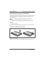
Installing an additional battery
Switch off the notebook.
Pull the power plug of the power supply unit out of grounded wall outlet
Close the cover of the notebook so that it locks into place on the left and right.
Disconnect any cables attached to the notebook.
Place the notebook bottom-up on a flat surface.
2
1
Push the floppy disk compartment's release tab in the direction of the arrow (1).
Remove the floppy disk drive from the compartment (2).
Insert the battery, contacts first, into the floppy disk compartment. The contacts
must face upwards.
Push the battery into the compartment until it clicks into place.
Turn the notebook over and place it on a flat surface with the underside facing
downwards.
Reconnect the cables you previously disconnected.
A26391-K64-Z100-2-7619
43
Operation
The battery
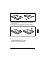
Removing the additional battery
Switch off the notebook.
Pull the power plug of the power supply unit out of grounded wall outlet
Close the cover of the notebook so that it locks into place on the left and right.
Disconnect any cables attached to the notebook.
Place the notebook bottom-up on a flat surface.
2
1
Push the floppy disk compartment's release tab in the direction of the arrow (1).
Pull the battery out of the floppy disk compartment (2).
Insert the floppy disk, contacts first, into the floppy disk compartment. The side
with the label should face towards the notebook's display.
Push the floppy disk into the compartment until you feel it click into place.
44
A26391-K64-Z100-2-7619
The battery
Operation
Deep-discharging/recharging the battery
The process of fully discharging and recharging the battery is necessary to ensure
that the battery charges fully. You should carry this out once a month and
– after charging the battery for the first time (e.g., when you use the notebook for
the first time)
– if you have not used the notebook for a longer period of time (e.g., a week)
– if the battery charge does not last as long as usual
– if the battery gets hot while charging
– if the charge segments in the battery symbol start to flash.
Switch off the notebook.
Pull the power plug of the power supply unit out of grounded wall outlet
Disconnect any cables attached to the notebook.
Run the Setup program.
Choose Power Management Setup.
Set Deep Discharge to Enable.
Press the F10 function key twice.
The battery begins to discharge.
Leave the notebook switched on.
The notebook switches itself off when the battery is empty.
Fully recharge the battery.
If necessary, repeat the process.
i
If the battery becomes hot in spite of discharging and recharging the battery
or if the battery charge does not last as long as usual or if the charge
segments in the battery symbol start to flash, the battery should be
replaced.
When disposing of the old battery, pay attention to the safety instructions in
the section "Important notes".
A26391-K64-Z100-2-7619
45
Operation
Cleaning the notebook
Cleaning the notebook
!
Switch off the notebook and disconnect the power supply unit cable.
Only authorized service personnel may clean the inside of the casing.
Do not use scouring powder or cleaning agents that attack plastics.
Make sure that no liquids penetrate the notebook's casing.
Use a clean, dry cloth to clean the casing. If it is especially dirty, use a cloth lightly
moistened in water and mild washing-up liquid.
To clean the keyboard, you can use disinfectant wipes.
To clean the display, you can use a soft, lightly moistened cloth.
Cleaning the trackball mechanism
2
3
1
4
Insert a pointed object (e.g., a ballpoint pen) into the recess in the retaining ring
and push the ring counterclockwise a quarter-turn (1).
Remove the retaining ring and the trackball from the notebook (2).
Clean the trackball mechanism and the trackball with a lint-free cloth.
Put back the trackball and the retaining ring (3).
Insert the pointed object or ballpoint pen in the recess in the retaining ring and
push the ring clockwise a quarter-turn (4). You should feel it click into place.
46
A26391-K64-Z100-2-7619
Re-formatting the hard disk
Operation
Rebuilding the hard disk
If you have created a bootable system disk (floppy disk) and have backed up the
hard disk, you can reformat and rebuild the hard disk, and restore the versions of
directories and files stored on the hard disk at the time you performed the backup.
Use the system disk to boot the PC from the floppy disk drive.
Use the MS-DOS command FDISK to partition the hard disk. (This requires
sound knowledge of the system.)
Use the MS-DOS command FORMAT with the /s option (e.g., FORMAT C:/s) to
format the hard disk.
The /s option causes the system files that start the operating system to be
transferred to the hard disk.
Copy the files of the backup program MSBACKUP from the system disk to the
hard disk (e.g., COPY A:\MSB*.* C:\ ↵ ).
Switch to the hard disk (e.g., C: ↵ ).
Start the backup program MSBACKUP (MSBACKUP ↵ ).
Restore your files from your backup disks to the hard disk with the backup
program's RESTORE function.
If these steps fail to correct the problem with your hard disk, it will have to be
replaced.
A26391-K64-Z100-2-7619
47
Operation
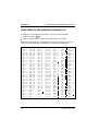
Code table for the standard character set
Code table for the standard character set
To display one of the following characters on screen, proceed as follows:
Press and hold the Alt key.
Enter the appropriate three-digit code for the character you require.
Characters 000 through 031 are displayed on screen as characters, but they are
really control characters and are therefore not included in the table below.
032
033
034
035
036
037
038
039
040
041
042
043
044
045
046
047
048
049
050
051
052
053
054
055
056
057
058
059
060
061
062
063
48
=
=!
="
=#
=$
=%
=&
='
=(
=)
=*
=+
=,
=–
=.
=/
=0
=1
=2
=3
=4
=5
=6
=7
=8
=9
=:
=;
=<
==
=>
=?
064 = @
065 = A
066 = B
067 = C
068 = D
069 = E
070 = F
071 = G
072 = H
073 = I
074 = J
075 = K
076 = L
077 = M
078 = N
079 = O
080 = P
081 = Q
082 = R
083 = S
084 = T
085 = U
086 = V
087 = W
088 = X
089 = Y
090 = Z
091 = [
092 = \
093 = ]
094 = ˆ
095 = _
096 =
097 =
098 =
099 =
100 =
101 =
102 =
103 =
104 =
105 =
106 =
107 =
108 =
109 =
110 =
111 =
112 =
113 =
114 =
115 =
116 =
117 =
118 =
119 =
120 =
121 =
122 =
123 =
124 =
125 =
126 =
127 =
`
a
b
c
d
e
f
g
h
i
j
k
l
m
n
o
p
q
r
s
t
u
v
w
x
y
z
{
}
~
128 =
129 =
130 =
131 =
132 =
133 =
134 =
135 =
136 =
137 =
138 =
139 =
140 =
141 =
142 =
143 =
144 =
145 =
146 =
147 =
148 =
149 =
150 =
151 =
152 =
153 =
154 =
155 =
156 =
157 =
158 =
159 =
Ç
ü
é
â
ä
à
å
ç
ê
ë
è
ï
î
ì
Ä
Å
É
æ
Æ
ô
ö
ò
û
ù
ÿ
Ö
Ü
¢
£
¥
Pt
ƒ
160 =
161 =
162 =
163 =
164 =
165 =
166 =
167 =
168 =
169 =
170 =
171 =
172 =
173 =
174 =
175 =
176 =
177 =
178 =
179 =
180 =
181 =
182 =
183 =
184 =
185 =
186 =
187 =
188 =
189 =
190 =
191 =
á
í
ó
ú
ñ
Ñ
ª
º
¿
¬
1/
2
1/
4
¡
«
»
192 =
224 = α
193 =
225 = β
194 =
226 = Γ
195 =
227 = π
196 = 228 = Σ
197 =
229 = σ
198 =
230 = µ
199 =
231 = τ
200 =
232 = Φ
201 =
233 = Ξ
202 =
234 = Ω
203 =
235 = δ
204 =
236 = ∞
205 =
237 = ∅
206 =
238 = ∈
207 =
239 = ∩
208 =
240 = ≡
209 =
241 = ±
210 =
242 = ≥
211 =
243 = ≤
212 =
244 = ⌠
213 =
245 = ⌡
214 =
246 = ÷
215 =
247 = ≈
216 =
248 = °
217 =
249 = ⋅
218 =
250 = −
219 =
251 = √
220 =
252 = n
221 =
253 = 2
222 =
254 =
223 =
255 =
A26391-K64-Z100-2-7619
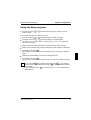
System configuration
You use the Setup program to configure your notebook's hardware and system
functions.
When it is supplied, the notebook is set to factory default settings which you can
alter in the Setup program's various submenus. Any changes you make take effect
as soon as you quit the Setup program or switch on the notebook.
The Setup program contains the following submenus:
– System Setup:
for setting the system time and date and configuring
the ports and the pointing device
– Video Setup:
for setting up the display
– Security Setup:
for setting up the security features
– Power Management:
for setting up the power-management features
– Docking Unit Setup:
for configuring the docking unit (this option is only
available if the notebook is connected to a docking unit.)
A26391-K64-Z100-2-7619
49
System configuration
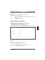
Starting the Setup program
Starting the Setup program
Reboot the notebook (switching on/off or warm boot).
When the message Press Fn + Esc for Setup appears, press the key
combination Fn + Esc .
i
If the external keyboard does not feature an Fn key, you can
simultaneously press the Alt and Shift keys instead.
If a setup password has been defined:
Enter the setup password and press the Enter key.
If you have forgotten the setup password:
Insert the disk System Utilities in the notebook's floppy disk drive.
Press the key combination Fn + F6 .
If you have forgotten the Setup password and it is not stored on the System
Utilities disk or the System Utilities disk is no longer available, please
contact our customer service.
The Setup program's main menu is displayed.
F3A21
Setup
03.07.95
---------------------------------------------------------------------------
System Setup
Video Setup
Security Setup
Power Management
[Docking Unit Setup]
--------------------------------------------------------------------------Esc
F3
F10
Enter
↑↓
Exit
Set Default
Save
Submenu
Field
The Setup program's main menu
50
A26391-K64-Z100-2-7619
Using the Setup program
System configuration
Using the Setup program
Use the cursor key ↑ or ↓ to select the submenu you wish to access to
make changes.
Press the Enter key. The submenu opens.
Use the cursor key ↑ or ↓ to select the item you wish to change.
Press the cursor key ← or → until the setting you require appears.
The items System Password, Setup Lock and Docking Unit Password require that
you enter normal text.
Repeat the last two steps described for all the items you wish to change.
Make a note of the changes you have made (here in this manual, for example).
Press the function key F10 .
The changes you have made are saved temporarily. The main menu appears
again.
Change any other settings you wish in the other submenus.
Press the function key F10 .
The changes you have made are stored and Setup ends. The notebook reboots.
i
If you press the Esc key instead of the function key F10 , your changes
are not saved. If you press the function key F3 , all the entries are reset to
their defaults.
If you press function key F3 in the submenu Security Setup, all passwords
will be deleted.
A26391-K64-Z100-2-7619
51
System configuration
System settings - System Setup
Changing the system settings - System Setup
In the System Setup submenu you can set up the following:
– the time (in the field marked Time)
– the date (in the field marked Date)
– the serial port (in the field marked COM Port)
– the parallel port (in the field marked LPT Port)
– the cache memory (in the field marked Cache Memory)
– the pointing devices (in the field marked Pointing Device)
– the power-on self-test (in the field marked Pointing Device)
F3D31
System Setup
01.09.95
--------------------------------------------------------------------------Time (H:M:S):
HH:MM:SS
Date (D.M.Y):
DD.MM.YY
[Internal Floppy Drive:
[External Floppy Drive:
Drive A
Drive B
Internal Hard Disk:
[External Hard Disk:
Auto
Auto
Base Memory:
Extended Memory:
640KB
7MB
1.44MB 3.5Inch]
1.2MB 5.25Inch]
Cyl
1016
1016
Hd
16
16
Sec
63
63
Mbyte
500
500]
Shadow BIOS:
Cache Memory:
Enable
Enable
COM Port:
COM1
Pointing Device:
PS/2 Type
IR Port:
COM2
Quick Boot:
Disable
LPT Port:
LPT1
Audio Device:
220h
Mode:
Bidirectional
--------------------------------------------------------------------------Esc
F3
F10
↑↓
←/→
Main Menu
Set Default
Save
Field
Value
The System Setup submenu
Time
Date
The Time field and the Date field indicate the time and date according to the
notebook's built-in clock. If you change these settings, enter the time in the format
HH:MM:SS (hours:minutes:seconds) and enter the date in the format DD.MM.YYYY
(day/month/year).
Internal Floppy Drive
External Floppy Drive
These two fields show the types of floppy drive installed in the notebook (internal)
and in the docking unit (external). If a floppy disk drive is not installed or the
docking unit is not connected, the relevant item does not appear on the display.
52
A26391-K64-Z100-2-7619
System settings - System Setup
System configuration
Internal Hard Disk
External Hard Disk
These two fields show the types of hard disk installed in the notebook (internal) and
in the docking unit (external). The external hard disk type only appears if the
notebook is attached to a docking station in which a hard disk is installed.
Base Memory
This field shows the amount of base memory available below 1 Mbyte.
Extended Memory
The Extended Memory field shows the amount of available memory above 1 Mbyte.
COM Port
This field is used to specify the port address and the interrupt request used by the
serial port.
COM1
The serial port uses the address 3F8h and IRQ4 (default).
COM2
The serial port uses the address 2F8h and IRQ3.
Disable
The serial port is disabled.
IR Port
This field defines the address and the interrupt for the serial interface.
COM1
The infrared interface is set to address 3F8h and IRQ4.
COM2
The infrared interface is set to address 2F8h and IRQ3 (default
entry).
Disable
The infrared interface is disabled.
LPT Port
This field is used to specify the address and the interrupt used by the parallel port.
LPT1
The parallel port uses the address 378h and IRQ7 (default).
LPT2
The parallel port uses the address 278h and IRQ5.
Disable
The parallel port is disabled.
A26391-K64-Z100-2-7619
53
System configuration
System settings - System Setup
Mode
This field defines whether the parallel port is used as an input/output device or just
as an output device. The EPP and ECP transmission modes can also be enabled.
The data transmission rates can be increased to 2 and 2.4 MB/s with these modes.
The peripheral equipment and associated drivers which support these modes are
required. (see Documentation of peripheral equipment).
Bidirectional
EPP 1.7
EPP 1.9
Extended (ECP)
Unidirectional
Data can be received and transmitted (default).
EPP1.7 standard transmission mode (enhanced parallel port).
EPP1.9 standard transmission mode (enhanced parallel port).
Extended capability port transmission mode.
Data can only be transmitted.
Shadow BIOS
The Shadow BIOS field is always set to Enable.
The system BIOS is copied to faster RAM when the notebook is switched on.
Cache Memory
This field is used to enable and disable the cache memory.
If the access time is too fast for certain application programs, you should disable
the cache memory.
Enable
Disable
Part of main memory is mapped to high-speed cache memory.
(default).
The cache memory is not used.
Pointing Device
This field is used to specify the type of pointing device used.
PS/2 Type
Serial Type
Select this option to use the built-in trackball or a PS/2 mouse
(default).
Select this option if you wish to use a serial mouse. If you use a
serial mouse, you will have to load the appropriate device driver.
Quick Boot
This field is used to specify the type of power-on self-test carried out by the
notebook.
Enable
Disable
54
A short, limited-scope test is carried out when the notebook is
switched on.
A longer, full test is carried out when the notebook is switched on
(default).
A26391-K64-Z100-2-7619
Display settings - Video Setup
System configuration
Audio Device
This field is used to specify the address for the audio device.
220h (default entry), 230h, 240h and 250h
You have to change this field only if another device uses the default
address 220h.
Disable
The audio device is disabled.
Display settings - Video Setup
You can select the following settings in the Video Setup submenu:
– the display device (in the field marked Display Device)
– the display attributes (in the field marked Reverse Video)
– the on-screen image size (in the field marked Expanded Mode)
F3D31
Video Setup
01.09.95
---------------------------------------------------------------------------
Panel Type:
Color TFT LCD
Display Device:
LCD
[Reverse Video:
Disable]
Expanded Mode:
Enable
External Monitor:
VGA
--------------------------------------------------------------------Esc
F3
F10
↑↓
←/→
Main Menu
Set Default
Save
Field
Value
The Video Setup submenu
Panel Type
This field shows the notebook's built-in display type.
Monochrome LCD monochrome display
Color DSTN LCD DSTN (Double Super Twisted Nematic) color
Color TFT LCD
TFT (Thin Film Transistor) color
A26391-K64-Z100-2-7619
55
System configuration
Display settings - Video Setup
Display Device
This field is used to specify the display device.
LCD
Just the notebook's internal display is used (default).
CRT
Just the external display is used.
LCD&CRT
The notebook's internal display and the external display are used.
The DSTN color display does not allow this setting.
Reverse Video
This field is only displayed if your notebook is fitted with a monochrome or DSTN
color display.
You specify whether, and how, reverse video is to be used.
Disable
Produces dark characters on a light background (default).
Text Only
Light characters on a dark background in text mode.
Text&Graphics Light characters on a dark background in text and graphics modes.
Expanded Mode
This field controls the on-screen image size in video modes that drive less than 480
lines.
Disable
400 lines are centered vertically on the display.
Enable
The video output is expanded to fill the full available screen area
(default).
External Monitor:
With this field you can select the refresh rate for the external monitor. It appears
only at PCD 5ND.
VGA
The external monitor has a refresh rate of 60 Hz. (default entry)
Enhanced
The external monitor has a refresh rate of 70 Hz.
56
A26391-K64-Z100-2-7619
Setting up security features - Security Setup
System configuration
Setting up the security features - Security Setup
You can set up the following security features in the Security Setup submenu:
– Control of system start-up (in the field marked System Lock)
– Locking of input devices (in the field marked Keyboard Lock)
– Control of access to the Setup program (in the field marked Setup Lock)
– Control of access to the docking unit (in the field marked
Docking Unit Password)
– Prevention of system boots from floppy disk (in the field marked Boot Device)
– Prevention of write operations to floppy disk (in the field marked Diskette Write)
– Prevention of write operations to PCMCIA cards (in the field marked
PC Card Write)
– Serial port locking (in the field marked Serial Interface)
– Infrared interface locking (in the field marked IR Interface
– Parallel part locking (in the field marked Parallel Interface)
F3D31
Security Setup
01.09.95
--------------------------------------------------------------------------System Password:
System Lock:
Keyboard Lock:
Setup Lock:
Not Set
Disable
Disable
Disable
[Docking Unit Password:
Disable]
Boot Device:
Floppy Drive
Diskette Write:
Enable
PC Card Write:
Enable
Serial Interface:
IR-Interface:
Parallel Interface:
Enable
Enable
Enable
--------------------------------------------------------------------------Esc
F3
F10
↑↓
←/→
Main Menu
Set Default
Save
Field
Value
The Security Setup submenu
A26391-K64-Z100-2-7619
57
System configuration
Setting up security features - Security Setup
System Password
You can specify a system password in this field. Depending on the System Lock and
Keyboard Lock settings, the system password allows the system to boot, or unlocks
the input devices.
If you do not specify a different password in Setup Lock, the system password will
also permit access to the Setup program. Default: Not Set
Make a note of your passwords, and store the written note and the System
Utilities diskette (with the stored setup password) in a secure place.
i
To specify or alter the system password:
Select System Password.
Enter the system password and press the Enter key.
The system password can consist of a maximum of eight letters or numbers.
Enter the system password a second time to confirm it and press the Enter key.
The following message is displayed:
New password is now installed, press any key ...
Press any key to continue.
If you do not wish to change the current system password:
Select another item that you wish to change.
System Lock
In this field you select whether the system start-up is to be restricted by means of
the system password.
Enable
You can only select this option if you have specified a system
password.
Whenever the notebook is switched on or warm-booted, the
keyboard lock is released, or the notebook comes out of suspend
mode you have to enter the system password before the system
will boot.
Disable
The system will boot without the entry of a password (default).
58
A26391-K64-Z100-2-7619
Setting up security features - Security Setup
System configuration
Keyboard Lock
You use this field to specify whether the keyboard, trackball and mouse should be
locked. If the input devices are locked, you can unlock them by entering the system
password.
You can only select this option if you have specified a system
password.
Using the key combination Fn + Scroll Lock you can lock the input
devices and switch off the display.
Enable
1 Minute, 2 Minutes, 3 Minutes, 4 Minutes or 5 Minutes
You can only select this option if you have specified a system
password.
If the notebook receives no input within the period of time specified,
the input devices are locked and the display is switched off.
You can also lock the input devices and switch off the screen by
pressing the key combination Fn + Scroll Lock .
The input devices cannot be locked (default).
Disable
Setup Lock
You use this field to enable and disable password-protection for the Setup program.
The setup password can consist of a maximum of eight letters or numbers.
i
Make a note of your passwords, and store the written note and the
System Utilities diskette (with the stored setup password) in a secure place.
Enable
The setup password has to be entered before the Setup program
will start.
This field is automatically set to Enable if System Lock or
Keyboard Lock is set to Enable. If you do not specify a separate
setup password, you have to enter the system password in order to
run Setup.
Disable
You can only select this option if System Lock and Keyboard Lock are
set to Disable.
You will then be able to start Setup without having to enter a
password (default).
A26391-K64-Z100-2-7619
59
System configuration
Setting up security features - Security Setup
If you want to specify or change a setup password:
Select Setup Lock.
Select Enable.
Enter a setup password and press the Enter key.
Enter the setup password a second time to confirm it and press the Enter key.
The following message is displayed:
New password is now installed, press any key ...
Press any key to continue.
Select Setup Lock.
Insert the disk System Utilities in the floppy disk drive.
Press the Enter key.
The setup password is saved in encrypted form on the disk System Utilities.
If you have not defined a setup password and you wish to use the system
password as the setup password:
Select Setup Lock.
If the field is set to Disable, change this setting to Enable.
Insert the disk System Utilities in the floppy disk drive.
Press the Enter key.
The setup password is saved in encrypted form on the disk System Utilities.
60
A26391-K64-Z100-2-7619
Setting up security features - Security Setup
System configuration
If you do not wish to use the system password as the setup password or if you wish
to change the setup password:
Select Setup Lock.
Enter the new setup password and press the Enter key.
Enter the new setup password a second time to confirm it and press the Enter
key. The following message is displayed:
New password is now installed, press any key ...
Press any key to continue.
Select Setup Lock.
Insert the disk System Utilities in the floppy disk drive.
Press the Enter key.
The setup password is saved in encrypted form on the disk System Utilities.
Docking unit password
This field only appears if the notebook is connected to a docking unit. It lets you
specify whether docking-unit access is to be controlled by means of a password.
Enable
You have to enter a password in order access the docking unit.
Disable
You can access the docking unit without having to enter a
password (default).
If you wish to specify a docking unit password:
Select Docking Unit Password.
If the field is set to Disable, change this setting to Enable.
Enter a docking unit password and press the Enter key.
The password can consist of a maximum of eight letters and numbers.
Enter the docking unit password a second time to confirm it and press the Enter
key. The following message is displayed:
New password is now installed, press any key ...
Press any key to continue.
A26391-K64-Z100-2-7619
61
System configuration
Setting up security features - Security Setup
Boot Device
In this field you specify the boot device (the device from which the operating
system is loaded).
Floppy Drive
The BIOS attempts to boot the system from floppy drive A:. If A:
does not contain a bootable system disk, it tries to boot from the
hard disk, drive C: (default).
Hard Disk
The BIOS always boots the system from the hard disk, drive C:.
PCMCIA
This option cannot be selected if the notebook is attached to
docking unit which contains a floppy disk drive.
The BIOS tries to boot the system from PCMCIA slot 1. If PCMCIA
slot 1 (the lower slot) does not contain a PCMCIA card with an
operating system on it, the system boots from drive C:.
Diskette Write
In this field you specify whether the notebook's floppy disk drive can write to, or
delete, floppy disks.
Enable
Floppy disks can be read, written and deleted (default).
Disable
Floppy disks can only be read.
PC Card Write
In this field you specify whether data can be written to PCMCIA cards installed in
the notebook.
Enable
PCMCIA cards can be read, written and deleted (default).
Disable
PCMCIA cards can only be read.
62
A26391-K64-Z100-2-7619
Setting up security features - Security Setup
System configuration
Serial Interface
In this field you specify whether data can be transferred across the notebook's
serial port.
Enable
The serial port is enabled, data can be transferred.
Disable
The serial port is disabled.
IR (infrared) Interface
In this field you specify whether data exchange is possible via the notebook's
infrared interface.
Enable
The infrared interface is enabled - data exchange is possible.
(default entry)
Disable
The infrared interface is disabled.
Parallel Interface
In this field you specify whether data can be transferred across the notebook's
parallel port.
Enable
The parallel port is enabled, data can be transferred
Disable
The parallel port is disabled.
A26391-K64-Z100-2-7619
63
System configuration
Power Management Setup
Setting up the power management features Power Management Setup
You can do the following in the Power Management Setup submenu:
– Enable/disable the power management features (in the field marked
Power Management)
– Specify the response to display output (in the field marked
Video Access Trigger)
– Enable/disable Doze mode (in the field marked Doze Mode)
– Enable/disable Standby mode (in the field marked System Auto Standby)
– Enable/disable Suspend mode (in the field marked System Auto Suspend)
– Enable/disable automatic display power-down (in the field marked
LCD Power Down)
– Enable/disable the hard disk's power saving features (in the field marked
Hard Disk Power Down)
– Set the CPU speed (in the field marked CPU Speed)
– Enable/disable the system speaker (in the field marked System Speaker)
– Deep-discharge the battery (in the field marked Deep Discharge)
F3A21
Power Management Setup
03.07.95
--------------------------------------------------------------------------Power Management:
Enable for Battery Powered Only
Video Access Trigger:
Enable
Doze Mode:
System Auto Standby:
System Auto Suspend:
Enable
2 Minutes
4 Minutes
LCD Powerdown:
Hard Disk Powerdown:
1 Minute
2 Minutes
CPU Speed:
System Speaker:
High
Enable
Deep Discharge:
Disable
--------------------------------------------------------------------------Esc
F3
F4
F5
F10
↑↓
←/→
Main Menu
Set Default
Long Life
High Performance
Save Field Value
The Power Management submenu
Long Life mode
You can select the Long Life mode by pressing function key F4 . The Long Life
mode uses all the available power management features to conserve power. The
notebook uses little power and operates slightly slower than usual.
To re-enable the default power management features, press function key F3 .
64
A26391-K64-Z100-2-7619
Power Management Setup
System configuration
High Performance mode
You can select High Performance mode by pressing function key F5 . In this mode
the notebook operates at maximum speed and uses the most power.
To re-enable the default power management features, press function key F3 .
Power Management
You use this field to specify when the power management features are to be used.
Enable for Battery Powered only
The power management features are only used if the notebook is
running on its built-in battery (default).
Disable
The power management features are not used.
Always Enable The power management features are permanently enabled.
Video Access Trigger
You use this feature to define how power management is to react to display output.
Enable
Output to the display is treated as system activity and resets the
timer (e.g., for LCD Power Down) (default).
Disable
Output to the display is not treated as system activity. You must
use this setting if you intend to use a screen saver or are running
OS/2.
Doze Mode
Enable
If the system registers no activity for a specific period of time, the
CPU speed is reduced to save power. Any resumption of activity
causes the CPU speed to return to normal (default).
Disable
The Doze mode is disabled.
A26391-K64-Z100-2-7619
65
System configuration
Power Management Setup
System Auto Standby
In this field you specify how long the notebook waits during a period without system
activity before switching to Standby mode.
1 Minute to 15 Minutes
If the notebook registers no system activity for the period specified
in this field, it switches to Standby mode. Any resumption of activity
re-activates the notebook.
(Default: 2 Minutes)
Disable
The feature is disabled.
System Auto Suspend
In this field you specify how long the notebook waits during a period without system
activity before switching from Standby mode to Suspend mode. This feature will
only work if a time is defined in System Auto Standby.
Battery Low Suspend
The notebook switches to Suspend mode five minutes after the
remaining battery power has dropped to below 10%.
1 Minute to 15 Minutes
If the notebook registers no system activity for the period specified
in this field, it switches from Standby mode to Suspend mode.
(Default: 4 Minutes)
Disable
The feature is disabled.
LCD Powerdown
In this field you specify the time after which the notebook powers down its display if
it is receiving no input. Any input it receives causes it to switch the display on
again.
1 Minute to 15 Minutes
If the notebook registers no input for the period defined in this field,
it switches off its display. (Default: 1 Minute)
Disable
66
The feature is disabled.
A26391-K64-Z100-2-7619
Power Management Setup
System configuration
Hard Disk Powerdown
In this field you specify the time after which the notebook powers down its hard disk
if it is not being accessed. The next attempt to access the hard disk powers it up
again.
1 Minute to 15 Minutes
If the hard disk is not accessed for the period defined, it is powered
down. (Default: 2 Minutes)
Disable
The feature is disabled.
CPU Speed
In this field you select the CPU speed.
High
The CPU operates at maximum speed (default).
Low
The CPU operates at reduced speed.
System Speaker
In this field you enable or disable the notebook's system speaker.
Enable
The system speaker is enabled (default).
Disable
The system speaker is disabled.
Deep Discharge
In this field you can specify that the built-in battery is to be fully discharged (see
chapter "Operation - The battery - Deep-discharging/recharging the battery".
Enable
The battery will be discharged, provided the notebook is left
switched on.
Disable
The feature is disabled (default).
A26391-K64-Z100-2-7619
67
System configuration
Docking Unit Setup
Configuring the docking unit - Docking Unit
Setup
The Docking Unit Setup submenu only appears if the notebook is attached to a
docking unit.
You can specify the following in Docking Unit Setup:
– Hard disk drive C: (in the field marked Hard Disk Boot)
– Floppy disk drive A: (in the field marked Diskette Boot)
– The docking unit's display controller (in the field marked Primary Display)
– The display controller used by the notebook (in the field marked Internal VGA)
– The type of pointing device (in the field marked Pointing Device)
F3D31
Docking Unit Setup
01.09.95
--------------------------------------------------------------------------External Diskette:
1.2MB
5.25Inch
External Hard Disk:
Auto
Hard Disk Boot:
Diskette Boot:
Internal
Enable
Primary Display:
Internal VGA:
Pointing Device:
VGA/EGA
Automatic
PS/2 Type
SCSI Drive:
I/O:
IRQ:
Disable
340h
11
Cyl
985
Hd
13
Sec
32
Mbyte
200
--------------------------------------------------------------------------Esc
F3
F10
↑↓
←/→
Main Menu
Set Default
Save
Field
Value
The Docking Unit Setup submenu
External Diskette
In this field you specify the type of floppy disk drive (if any) installed in the docking
unit.
Options:
360 KB, 720 KB, 1.2 MB, 1.44 MB, 2.88, and None (default: None)
Default entry: None
External Hard Disk
This field shows the type of hard disk installed in the docking unit.
68
A26391-K64-Z100-2-7619
Docking Unit Setup
System configuration
Hard Disk Boot
In this field you specify which hard disk is to be treated as hard disk C:. This is then
the hard disk from which the operating system is loaded.
Internal
The notebook's built-in hard disk is drive C: (default).
External
The hard disk in the docking unit is drive C:.
Disable
The hard disk in the notebook and the hard disk in the docking unit
are disabled.
Diskette Boot
In this field you specify which floppy disk drive is to be treated as drive A:. This is
then the floppy disk drive from which the operating system can be loaded.
Internal
The notebook's built-in floppy disk drive is drive A: (default).
External
The floppy disk drive in the docking unit is drive A:.
Primary Display
If the notebook's built-in display controller has been disabled, this field specifies the
type of display controller installed in the docking unit.
Options:
Default:
VGA/EGA, 40 color, 80 color, and Mono.
VGA/EGA
Internal VGA
This field is used to specify when the notebook's built-in display controller should
be disabled.
Automatic
If the notebook detects a display controller in the docking unit, the
notebook's own display controller is disabled (default).
Disable
If the notebook is attached to a docking station, its own display
controller is disabled.
A26391-K64-Z100-2-7619
69
System configuration
Docking Unit Setup
Pointing Device
This field is used to specify the kind of pointing device used. The entry in this field
takes precedence over the Pointing Device setting in the System Setup submenu.
PS/2 Type
Select this option if you wish to use the trackball or a PS/2 mouse
(default).
Serial Type
Select this option if you wish to use a serial mouse. If you use a
serial mouse, you will have to load the appropriate device driver.
SCSI Drive:
Enable
A SCSI drive can be incorporated in the docking unit.
Disable
No SCSI drive can be incorporated in the docking unit. (default
entry)
I/O:
140h
The I/O address for the SCSI drive incorporated in the docking unit
is 140h.
340h
The I/O address for the SCSI drive incorporated in the docking unit
is 340h. (default entry)
IRQ:
9
The interrupt for SCSI drive incorporated in the docking unit is 9.
10
The interrupt for SCSI drive incorporated in the docking unit is 10.
11
The interrupt for SCSI drive incorporated in the docking unit is 11.
(default entry)
15
The interrupt for SCSI drive incorporated in the docking unit is 15.
The fields SCSI Drive, I7O and IRQ appear only when a PCD-5ND is docked into a
docking unit II.
70
A26391-K64-Z100-2-7619
System expansion
!
Only use system upgrades that meet the requirements and guidelines
concerning safety, RFI, EMC and telecommunications terminal equipment
(see the section "Important notes").
Adding/removing memory (PCD-4ND)
The notebook PCD-4ND is fitted with a standard 4 Mbytes of main memory (RAM).
This can be increased to either 8 Mbytes or 20 Mbytes with a memory upgrade
card.
!
Only use memory upgrades designed specifically for this notebook.
Never use force when installing or removing a memory upgrade.
Make sure that foreign objects do not fall into the memory upgrade slot.
Installation
Switch off the notebook.
Close the cover of the notebook so that it locks into place on the left and right.
Disconnect any cables attached to the notebook.
Place the notebook bottom-up on a flat surface.
A26391-K64-Z100-2-7619
71
System expansion
Adding/removing memory (PCD 4ND)
1
2
3
Remove both screws (1).
Remove the memory slot cover (2).
Insert the memory upgrade, contacts first, into the slot (3). The labeled side of
the upgrade must face towards the notebook's display.
Gently push the memory upgrade into the slot until you feel it click into place.
2
1
Replace the cover (1).
Replace both screws (2).
Turn the notebook over and place it on a flat surface with the underside facing
downwards.
Reconnect the cables you previously disconnected.
72
A26391-K64-Z100-2-7619
Adding/removing memory (PCD 4ND)
System expansion
Removal
Switch off the notebook.
Close the cover of the notebook so that it locks into place on the left and right.
Disconnect any cables attached to the notebook.
Place the notebook bottom-up on a flat surface.
1
2
3
Remove both screws (1).
Remove the cover (2).
Pull the memory card out of the notebook as indicated by the arrow (3).
2
1
Replace the cover (1).
Replace both screws (2).
Turn the notebook over and place it on a flat surface with the underside facing
downwards.
Reconnect the cables you previously disconnected.
A26391-K64-Z100-2-7619
73
System expansion
Adding/removing memory (PCD-5ND)
Adding/removing memory (PCD-5ND)
The notebook PCD-5ND is fitted with a standard 8 Mbytes of main memory (RAM).
This can be increased to either 16 Mbytes, 24 Mbytes or 40 Mbytes with two
memory modules.
!
Only use memory modules designed specifically for this notebook.
Never use force when installing or removing a memory module.
Make sure that foreign objects do not fall into the memory module slot.
Installation
Switch off the notebook.
Close the cover of the notebook so that it locks into place on the left and right.
Disconnect any cables attached to the notebook.
Place the notebook bottom-up on a flat surface.
1
3
2
Remove both screws (1).
Remove the memory slot cover (2) by pulling in direction of the arrow (3).
74
A26391-K64-Z100-2-7619
Adding/removing memory (PCD-5ND)
System expansion
1
2
a
Insert the memory module, contacts first, into the slot (1).
The slot on memory module (a) must be in line with the corresponding part at
the mounting location.
Carefully flap the memory module down (2) until you feel it latch in place.
Install the second memory module in the same way.
4
a
2
1
3
Place the cover on its mounting location (1) and flap it into place on the
underside of the notebook (2).
Push the cover as far as it will go in the direction of the arrow (3).
Fasten the cover with the two screws (4).
Place the notebook bottom-down on a flat surface.
Reconnect the cables you disconnected earlier.
A26391-K64-Z100-2-7619
75
System expansion
Adding/removing memory (PCD-5ND)
Removal
Switch off the notebook.
Close the cover of the notebook so that it locks into place on the left and right.
Disconnect any cables attached to the notebook.
Place the notebook bottom-up on a flat surface.
1
3
2
Remove both screws (1).
Pull the cover in the direction of the arrow (2) and lift it off the notebook (3).
2
1
1
Carefully press the two retaining clips outwards (1).
The memory module will flap up.
Pull the memory module out of the notebook (2).
Remove the second memory module in the same way.
76
A26391-K64-Z100-2-7619
Installing/removing PCMCIA
System upgrades
4
a
2
1
3
Place the cover on its mounting location (1) and flap the cover into place on the
underside of the notebook (2).
Push the cover as far as it will go in the direction of the arrow (3).
Fasten the cover with the two screws (4).
Turn the notebook over and place it on a flat surface with the underside facing
downwards.
Reconnect the cables you previously disconnected.
Installing and removing PCMCIA cards
You can install either two 3.3mm (type I) or 5.5mm (type II) PCMCIA cards, or one
10.5mm (type III) PCMCIA card in the notebook.
!
The PCMCIA card must not consume more than 600mA (at +5V) or 60mA
(at +12V).
Consult the documentation supplied by the card's manufacturer and follow
the instructions provided.
Never use force when inserting or removing a PCMCIA card.
Make sure that foreign objects do not fall into the PCMCIA slot.
A26391-K64-Z100-2-7619
77
System upgrades
Installing/removing PCMCIA
Installation
Switch off the notebook.
1
2
Slide the cover in the direction of the arrow as far as it will go (1).
Insert the PCMCIA card, contacts first, into the slot guides (2). The labeled side
of the upgrade must be facing upwards.
Gently push the PCMCIA card into the slot until you feel it click into place.
i
Consult the documentation supplied with the PCMCIA card for information
on how to install the necessary device drivers.
For further information refer to the information files (*.txt, *.doc, *.wri)
provided with the PCMCIA driver diskette or the information under MSWindows.
If you are using PCMCIA cards that do not connect to external devices,
close the PCMCIA slot cover.
78
A26391-K64-Z100-2-7619
Installing/removing PCMCIA
System upgrades
Removal
Switch off the notebook.
3
1
2
Press the eject button (1). It will project further out of the notebook's case.
Pull the PCMCIA card out of the notebook (2).
Push the cover in the direction of the arrow (3) to close it.
A26391-K64-Z100-2-7619
79
System expansion
Connecting external devices
Connecting external devices
Disconnect all the devices from their respective power sources when you
connect or disconnect a device.
!
Consult the documentation supplied with an external device before
attempting to connect it.
Do not connect or disconnect cables during a storm.
When disconnecting cables, always hold them by the connector; do not pull
on the cable itself.
When connecting or disconnecting cables, carry out the following steps in
the sequence indicated:
Connecting cables
– Switch off all the relevant devices.
– Disconnect the AC power cords of all the relevant devices from the grounded
wall outlets.
– Connect all the cables to the notebook and the external devices. Pay attention
to the safety information provided in the section "Important notes".
– Connect all the data cables to the relevant data and telecommunications
network connectors.
– Reconnect the AC power cords to the grounded wall outlets.
Disconnecting cables
– Switch off all the relevant devices.
– Disconnect the AC power cords of all the relevant devices from the grounded
wall outlets.
– Disconnect all the data cables from the various data and telecommunications
network connectors.
– Disconnect all the cables connecting the notebook and the external devices.
80
A26391-K64-Z100-2-7619
Connecting external devices
System expansion
Port covers and connectors
i
If you have not attached any external devices, you should replace the port
cover to protect the port connectors from becoming soiled.
2
b
1
a
a = port cover
b = mouse/keyboard port cover
If you wish to connect an external display, a serial or parallel device, a docking unit
or a station box, you must first open the port cover:
Press down the release tab (1).
Fold down the port cover (2).
i
You fold the port cover away beneath the notebook, where it clips into
place.
If you wish to connect a PS/2 mouse or an external keyboard, you have to open the
cover for the mouse and keyboard ports:
Slide the cover (b) in the direction of the arrow as far as it will go.
i
If you have not connected a PS/2 mouse or external keyboard, close the
mouse and keyboard port cover to protect the port connectors from
becoming soiled.
A26391-K64-Z100-2-7619
81
System expansion
Connecting external devices
9
1
8
7
2
6
5
4 3
1 = Connector for external keyboard
2 = Connector for PS/2 mouse
3 = Connector for loudspeaker
4 = Audio connector
5 = Microphone connector
6 = Serial port connector
7 = Display connector
8 = Parallel port connector
9 = Connector for docking unit
Connecting serial or parallel devices
Connect the device's data cable to the appropriate port connector.
The serial port is configured by default as COM1. You can configure it as COM2 in
System Setup. The parallel port is configured by default as LPT1. You can configure it
as LPT2 in System Setup.
Connecting an external display
You can connect a VGA, SVGA (Super VGA) or multisync monitor. The notebook's
built-in display controller supports resolutions up to 1024 x 768 with 256 colors. If
you wish to use a resolution greater than 640 x 480, you must load the relevant
display drivers (see the manuals supplied with your display).
Connect the display's video signal cable to the notebook's display connector.
Connect the power cable of the external display to a grounded wall outlet and
switch on the display.
Switch on the notebook.
Configure the display output in Video Setup or by pressing the key combination
Fn + F12.
Select the resolution for the external display.
82
A26391-K64-Z100-2-7619
Connecting external devices
System expansion
Connecting a mouse
The trackball and the trackball buttons are disabled when you connect a mouse.
Connect the mouse to the appropriate port (PS/2 or serial).
Switch on the notebook.
In Video Setup, set Pointing Device to either PS/2 Type for a PS/2 mouse or
Serial Type for a serial mouse.
Install the necessary device driver (see the manual supplied with the mouse).
Connecting an external keyboard
Connecting an external keyboard disables the keyboard built into the notebook.
Connect the external keyboard to the external keyboard connector. If you wish
to connect a keyboard with a 5-pin connector you will require an adapter from 5pin DIN to 6-pin DIN mini connector.
Switch on the notebook.
i
Never press the keys on the external and internal keyboards at the same
time.
If the external keyboard does not have an Fn key, you can press the right
Ctrl key and the AltGr key together instead.
For example, to enter the key combination Fn + F1 on the external
keyboard you would press Ctrl + AltGr + F1 .
A26391-K64-Z100-2-7619
83
System expansion
Connecting external devices
Connecting a docking unit or station box
The manuals supplied with the docking unit and the station box describe how to
connect the notebook.
!
Read the docking unit or station box manuals carefully before attempting to
connect the notebook.
Make sure that neither PCMCIA cards nor the eject button are projecting out
of the side of the notebook.
i
If a VGA or SVGA display controller is installed in the station box, the
notebook's display is switched off.
Makes sure that any adapters installed in the docking unit or the station box
do not use I/O addresses, interrupts or DMA channels already used by the
notebook. Details of the I/O addresses, interrupts and DMA channels are
provided in the section "System specifications".
The maximum DMA transfer rate between Docking Unit and notebook is of
5 Mbyte/second.
If necessary, you can make the I/O addresses (e.g., for the display
controller) or the interrupts (e.g., for the serial or parallel port) available by
disabling the relevant components with the Setup program.
Close the PCMCIA slot cover.
Push the notebook into the docking unit or station box until you feel it click into
place.
Switch on the docking unit or station box.
Switch on the notebook.
Select the appropriate settings in Docking Unit Setup.
84
A26391-K64-Z100-2-7619
Changing keycaps
System expansion
Connecting external audio devices
If you attach an external microphone, the internal microphone is disabled. If you
attach an external loudspeaker, the internal loudspeaker is disabled.
Connect the audio device (external microphone, external loudspeaker) to the
connector of the notebook.
Transferring data with the infrared interface
The infrared interface enables a wireless data transfer.
By default, the infrared interface is set to COM2 in the setup. You can set it to
COM1 in the system setup.
i
The infrared interface can only be used, when the infrared interface (in
Security Setup) and the associated serial interface are enabled (in System
Setup and Security Setup)
Set up your devices as illustrated above. The devices may be no more than one
meter apart. The infrared transmitter and receiver operate over a range of 30˚.
A26391-K64-Z100-2-7619
85
System expansion
Changing keycaps
Changing the keycaps
If the keycaps on the keyboard do not match the country settings (selected when
the operating system is installed), you can fit the appropriate keycaps.
Information on which keycaps to change is provided with the replacement keycaps
and shows how the keyboard layout should appear once you have switched the
caps.
Lift off a keycap you wish to replace (e.g., with a screwdriver).
Be careful not to damage the neighboring keys.
In the case of the wide keys, hook the wire clip into the slot in the key switch unit
and the slot on the underside of the keycap.
Press the new keycap onto the key switch unit so that it clicks into place.
86
A26391-K64-Z100-2-7619
Troubleshooting
!
Pay attention to the safety instructions provided in the "Important notes" and
"Installation" sections when connecting and disconnecting cables.
If a fault occurs, try to correct it as described in the sections below. If you fail to
correct the problem, proceed as follows:
Switch off the notebook.
Make a note of the steps and the circumstances that led to the fault. Also make
a note of any error messages displayed.
Contact your sales office or customer service.
The POWER LED does not light up when the
notebook is switched on
If the POWER LED remains off, it can have the following causes:
The battery is not installed correctly
Switch off the notebook.
Check to ensure that the battery is installed correctly in its compartment.
Switch on the notebook.
The battery is dead
Recharge the battery or install a fully charged battery.
A26391-K64-Z100-2-7619
87
Troubleshooting
The power supply unit is not connected properly.
Switch off the notebook.
Check that the power supply unit is connected to the notebook properly.
Check that the AC power cord is connected properly to the power supply unit
and the grounded wall outlet.
Switch on the notebook. The LED on the power supply unit should light up.
The notebook's display remains blank
If the display remains blank, it can have the following causes:
The display is switched off
Press a key or enter the system password.
If the notebook is connected to a docking unit or station box in which a VGA or
SVGA adapter is installed, the notebook's display is always switched off.
The display's contrast or brightness has been turned down
Increase the contrast by pressing Fn + ← or increase the brightness with Fn +
↑ ).
The notebook has been configured to drive an external display
Press the key combination Fn + F12 or change the Display Device in Video Setup
setting to LCD or LCD&CRT.
i
88
A DSTN color display does not allow a display output at external and
notebook display at the same time.
A26391-K64-Z100-2-7619
Troubleshooting
The notebook's display is difficult to read
If the display is difficult to read:
Reflexes
Turn the notebook or alter tilt of the display.
The contrast is too low or too high
With a monochrome or DSTN color display:
Increase the contrast with Fn + ← or reduce it with Fn + → .
The brightness is too low or too high
Increase the brightness with Fn + ↑ or reduce it with Fn + ↓ .
The external display remains blank
If the display remains blank, it can have the following causes:
The display is switched off
Switch it on
The display has been blanked
Press a key to reactivate it.
The brightness control is turned down
Adjust the brightness control to increase the brightness. For further details,
consult the manual supplied with the display.
The notebook has been configured to drive the internal display
Press the key combination Fn + F12 or set Display Device in Video Setup to CRT
or LCD&CRT.
A26391-K64-Z100-2-7619
89
Troubleshooting
The external display's power cable or signal cable is not connected properly
Switch off the external display and the notebook.
Check that the external display's power cable is connected correctly to a
grounded wall outlet.
Check that the signal cable is connected correctly to the notebook and to the
display itself (if it is not permanently mounted).
Switch on the external display and the notebook.
The external display is blank or the image is
unstable
The wrong display resolution has been set for the external display or the
application.
Exit the application in Microsoft Windows by pressing Alt + F4 ↵ . If the error
persists when you exit the program, switch off the external display and then
switch it on again after a pause of at least three seconds.
Use Windows Setup to select the correct display resolution for the application.
90
A26391-K64-Z100-2-7619
Troubleshooting
The notebook seems to have locked up (crashed)
If the notebook seems to have locked up or crashed, it can have the following
causes:
The notebook is in Standby or Suspend mode
Reactivate the notebook by pressing a key (Standby mode) or by switching it on
(Suspend mode).
The application has locked up
Close the application or restart the notebook by power-cycling it or with a warm
boot.
The battery is dead.
Recharge the battery or install a fully charged battery.
The trackball does not respond
If the trackball does not work, it can have the following causes:
Incorrect settings in System Setup
Ensure that Pointing Device in System Setup is set to PS/2 Type.
No mouse driver installed
Ensure that the correct mouse driver has installed correctly before starting the
application.
The trackball or its mechanism is soiled
Switch off the notebook.
Clean the trackball and its mechanism.
Switch on the notebook.
A26391-K64-Z100-2-7619
91
Troubleshooting
The mouse does not respond
If the mouse does not work, it can have the following causes:
Incorrect settings in System Setup
Check the Pointing Device setting in System Setup.
If a PS/2 mouse is connected to the notebook, the field should be set to PS/2
Type.
If a serial mouse is connected, it should be set to Serial Type.
Check the correct Com Port setting in System Setup. The serial interface must be
enabled.
Check the correct Serial Interface setting in Security Setup. The serial interface
must be enabled.
No mouse driver installed
Ensure that the correct mouse driver has installed correctly before starting the
application. For information on the mouse driver, consult the manuals supplied
with the mouse or your application.
The mouse is not properly connected
Switch off the notebook.
Check to ensure that the mouse cable is connected to the notebook properly.
If you are using an adapter or extension cable, check the connections here, too.
Switch on the notebook.
The notebook will not write to floppy disk
Check whether that floppy disk is OK and is not write-protected.
Ensure that Diskette Write in Security Setup is not set to Enable.
92
A26391-K64-Z100-2-7619
Troubleshooting
The battery drains quickly or becomes hot
Deep-discharge and recharge the battery.
If this does not correct the problem, the battery should be replaced. When
disposing of the old battery, pay attention to the safety instructions in the section
"Important notes".
The PC's date or time is incorrect
Change the time and/or date in System Setup.
i
If the date and time are repeatedly incorrect when you switch on the
notebook, the backup battery that supplies the internal clock is dead.
Connect the notebook via its power supply unit to a grounded wall outlet or
install a fresh battery. The backup battery will charge fully in roughly two
days.
The printer does not print
Makes sure that the printer is switched on and on-line (see the manuals
supplied with the printer).
Check that the printer cable connecting the notebook and the printer is
connected properly.
Make sure that the port you are using to address the printer has been
configured correctly in your application, in Microsoft Windows and in MS-DOS.
Check that the correct printer driver is installed.
Check System Setup and Security Setup to ensure that the port you are using is
configured correctly. The COM Port or LPT Port setting, or the Serial Interface or
Parallel Interface setting, should match the settings in your application, in
Microsoft Windows and in MS-DOS.
A26391-K64-Z100-2-7619
93
Troubleshooting
The battery symbol is flashing
The battery is dead or no battery is installed
It the BATTERY LED is flashing, the battery is empty. If the BATTERY LED
is off, there is no battery in the notebook.
Ensure that the battery has been installed correctly.
Or
Recharge the battery.
The battery is defective
The number next to the battery symbol indicates which battery has failed: 1
means the standard battery; 2 means the second battery.
Deep-discharge and recharge the battery.
If this does not correct the problem, the battery should be replaced. When
disposing of the old battery, pay attention to the safety instructions in the section
"Important notes".
Acoustic warnings
A beep sounds every few seconds
The battery is almost drained.
Recharge the battery.
A single continuous beep
The notebook cannot switch to Standby or Suspend mode because the hard disk
or floppy disk is being accessed, or because there is insufficient space on the hard
disk.
Wait until the read/write operations to the hard disk or floppy disk have finished
or clear some space on the hard disk.
Three long beeps
The notebook cannot restore the programs that were active when it switched to
Suspend mode.
94
A26391-K64-Z100-2-7619
Troubleshooting
On-screen error messages
This section describes the error messages displayed by the system BIOS. Error
messages displayed by the operating system or programs are described in the
relevant manuals.
Diskette read failure - press F1 to retry boot
The system disk is defective.
Insert a working system disk.
Press the function key F1 .
Incorrect diskette, insert the utility diskette.
Press ENTER key after ready to backup.
The password cannot be saved to the disk you have inserted.
Insert the disk System Utilities.
Press the Enter key.
No boot device available - press F1 to retry boot
The operating system will not load because the hard disk is not connected is
has failed.
The operating system can be loaded from drive A: or from a PCMCIA card.
Which, depends on whether Boot Device is set to Floppy Drive or PCMCIA in
System Setup.
If the notebook is connected to a docking unit with floppy disk drive, the
operating system cannot be loaded from a PCMCIA card. If you wish to boot
from drive A:, the Diskette Boot setting has to be changed to Internal or
External.
Insert a system disk or a bootable PCMCIA card.
Press the function key F1 .
A26391-K64-Z100-2-7619
95
Troubleshooting
No boot sector on fixed disk - press F1 to retry boot
The hard disk is not bootable or it has not been formatted.
The operating system can be loaded from drive A: or from a PCMCIA card.
Which, depends on whether Boot Device is set to Floppy Drive or PCMCIA in
System Setup.
If the notebook is connected to a docking unit, the operating system cannot
be loaded from a PCMCIA card. If you wish to boot from drive A:, the Diskette
Boot setting has to be changed to Internal or External.
Insert a system disk or a bootable PCMCIA card.
Press function key F1 .
Not a boot disk - press F1 to retry boot
The disk in the floppy drive is not a system disk.
Remove the floppy disk from the drive.
Press the function key F1 .
If you wish to boot from floppy disk:
Insert a system disk.
Press function key F1 .
Real time clock failure
Invalid configuration information - please run setup Program
Press the F1 key to continue, F2 to run the setup utility
The system configuration information is incorrect.
Press function key F2 .
Reconfigure the system.
If the error message is displayed again, the notebook's backup battery is
empty.
Connect the notebook via its power supply unit to a grounded wall outlet or
install a fresh battery. The backup battery will charge fully in roughly two
days.
96
A26391-K64-Z100-2-7619
Troubleshooting
Resume not possible in the docking unit.
Please, switch off, disconnect the notebook from the docking
unit for resume
OR
press <F1> for continue and lose the suspended state.
If the notebook is connected to a docking unit, it cannot restore the programs
that were active when it switched to Suspend mode.
If you press function key F1 , the suspended system status will be lost.
Switch off the notebook and the docking unit.
Remove the notebook from the docking unit.
Switch on the notebook.
Verification of your password was incorrect!
The original password remains unchanged.
Press any key to continue.
You have entered the wrong password in confirmation.
Press any key.
Press the cursor key ↓ .
Press the cursor key ↑ .
Enter the password again and confirm it.
A26391-K64-Z100-2-7619
97
System specifications
Notebook PCD-4ND
CPU:
Math coprocessor:
Cache:
Memory (RAM):
System ROM (flash EPROM):
Disk drives:
SL enhanced processor
i486 SX, i486 DX2 or i486 DX4
integrated in i486 DX2 and i486 DX4
8 Kbytes, integrated in i486 SX, i486 DX2
16 Kbytes, integrated i486 DX4
4 Mbytes, upgradable to 8 or 20 Mbytes
128 Kbytes for system and video BIOS
Floppy disk drive for 3 1/2-inch floppy disks
Hard disk
Display:
– Resolution:
– Monochrome, 64 gray scales:
– Color (DSTN), 256 colors:
– Color (TFT), 256 colors:
– Color (TFT), 256 colors:
Backlit liquid-crystal transmissive display
640x480, or 25 80-character lines
24 cm diagonal (9.5 inches)
26 cm diagonal (10.2 inches)
24 cm diagonal (9.5 inches)
26 cm diagonal (10.2 inches)
Display controller:
WD 90C24A2 on VESA local-bus with
Windows accelerator
1 Mbyte
up to 1024x768 with 256 colors and 60 Hz
– Video memory:
– Resolutions:
(on external display)
Audio:
– Compatibility:
– A/D and D/A conversion:
Soundchip ES688
Soundblaster Pro, MS-Soundsystem
16 bit, stereo
Input devices
– Keyboard:
– Trackball:
86 keys
19 mm diameter
Slots
– PCMCIA:
– Memory:
2 x type I/type II or 1 x type III
4 Mbytes or 16 Mbytes
A26391-K64-Z100-2-7619
99
System specifications
Notebook, power supply unit
Ports
– PS/2 mouse port:
– External keyboard connector:
– Docking unit connector:
– Parallel port:
6-pin mini DIN female connector
6-pin mini DIN female connector
200-pin female connector
25-pin female connector, bi-directional,
EPP-capable
– External display connector:
15-pin female connector
– Serial ports:
9-pin male connector, 16550-compatible
– Microphone connector:
connector, mono
– Audio connector:
connector, stereo
– Connector for external loudspeaker: connector, stereo
– Infrared interface
Power consumption:
30 W max.
(notebook on with battery charging)
Temperature
– Operation:
– Transportation:
5 ˚C .... 35 ˚C
-20 ˚C .... 60 ˚C
Dimensions (W x D x H)
– with monochrome display:
– with color display:
297 mm, 220 mm, 46 mm
297 mm, 220 mm, 49 mm
Weight without battery
– with monochrome display:
– with color display:
3 kg (29.43 N)
3.3 kg (32.37 N)
Notebook PCD-5ND
CPU:
Math coprocessor:
Cache:
Memory (RAM):
Mbytes
System ROM (flash EPROM):
Disk drives:
100
Pentium P54C/LM processor
integrated in processor
16 Kbytes, integrated in processor
256 Kbytes second-level cache
8 Mbytes, upgradable to 16, 24 or 40
128 Kbytes for system and video BIOS
Floppy disk drive for 3 1/2-inch floppy disks
Hard disk
A26391-K64-Z100-2-7619
Notebook, power supply unit
System specifications
Display:
– Resolution:
– Color (DSTN), 256 colors:
– Color (TFT), 256 colors:
Backlit liquid-crystal transmissive display
640x480 or 800x600
26 cm diagonal (10.2 inches)
24 cm diagonal (9.5 inches)
Display controller:
C&T 65545 on VESA local-bus with
Windows accelerator
1 Mbyte
up to 1024x768 with 256 colors and 60 Hz
– Video memory:
– Resolutions:
(on external display)
Audio:
– Compatibility:
– A/D and D/A conversion:
Soundchip ES688
Soundblaster Pro, MS-Soundsystem
16 bit, stereo
Input devices
– Keyboard:
– Trackball:
86 keys
19 mm diameter
Slots
– PCMCIA:
– Memory:
2 x type I/type II or 1 x type III
8 Mbytes, 16 Mbytes or 32 Mbytes
Ports
– PS/2 mouse port:
– External keyboard connector:
– Docking unit connector:
– Parallel port:
6-pin mini DIN female connector
6-pin mini DIN female connector
200-pin female connector
25-pin female connector, bi-directional,
EPP-capable
– External display connector:
15-pin female connector
– Serial ports:
9-pin male connector, 16550-compatible
– Microphone connector:
connector, mono
– Audio connector:
connector, stereo
– Connector for external loudspeaker: connector, stereo
– Infrared interface
Power consumption:
Temperature
– Operation:
– Transportation:
A26391-K64-Z100-2-7619
30 W max.
(notebook on with battery charging)
5 ˚C .... 35 ˚C
-20 ˚C .... 60 ˚C
101
System specifications
Notebook, power supply, battery
Dimensions (W x D x H)
– with color display:
297 mm, 220 mm, 49 mm
Weight without battery
– with color display:
3.3 kg (32.37 N)
Power supply unit
Primary
– Rated voltage:
– Rated frequency:
– Max. rated current:
90 V to 269 V
47 Hz to 63 Hz
0.5 A (at 180 V) / 1 A (at 90 V)
Secondary
– Rated voltage:
– Max. rated current:
22.8 V
1.5 A
Dimensions (W x D x H):
112 mm, 58 mm, 29 mm
Weight without AC cord:
256 g (2.45 N)
Battery
Rated voltage:
14.4 V
Rated capacity:
1.8 Ah
Dimensions (W x D x H):
105 mm, 110 mm, 20 mm
Weight:
510 g (5 N)
102
A26391-K64-Z100-2-7619
I/O addresses, interrupts and DMA channels
System specifications
I/O addresses, interrupts and DMA channels
Function
I/O address
DMA controller #1, 8237
Interrupt controller #1, 8259
Timer, 8254
Keyboard and mouse controller
Real-time clock/NMI controller
DMA register
Fast A20 gate and CPU reset
Interrupt controller #2, 8259
DMA controller #2, 8237
Clear FPU
Reset FPU
ACC2066 register
FPU
Hard disk controller
Soundchip ESS688
000H – 01FH
020H – 030H
040H – 050H
060H – 06FH
070H – 07FH
080H – 09FH
092H
0A0H – 0BFH
0C0H – 0DFH
0F0H
0F1H
0F2H – 0F3H
0F8H, 0FCH, 0FEH
1F0H – 1F8H
220H – 22FH
388H – 38BH
278H – 27FH
2F8H – 2FFH
378H – 37FH
3B0H – 3DFH
3E0H – 3E3H
3F0H – 3F7H
3F8H – 3FFH
Parallel port LPT2
Serial port COM2
Parallel port LPT1
Display controller
PCMCIA controller
Floppy disk controller
Serial port COM1
A26391-K64-Z100-2-7619
Interrupt
DMA
IRQ0
IRQ1, IRQ12
IRQ8
DRQ0
IRQ14
IRQ5
DRQ1
IRQ5
IRQ3
IRQ7
IRQ6
IRQ4
DRQ2
103
System specifications
Pin assignment
Pin assignment
The pin assignments of external ports are described on the following pages.
DC input connector
No.
1
2
1
2
Description
0V
+22.8 V
Port for external keyboard and PS/2 mouse
Pin
6
4
2
104
5
3
1
1
2
3
4
5
6
Signal/Description
DATA
NC
0V
+5 V
CLOCK
NC
A26391-K64-Z100-2-7619
System specifications
Pin assignment
Serial port
1
5
6
9
Pin
Signal
Description
1
2
3
4
5
6
7
8
9
DCD
RxD
TxD
DTR
GND
DSR
RTS
CTS
RING
Data Carrier Detect
Receive Data
Transmit Data
Data Terminal Ready
Signal Ground
Data Set Ready
Request to Send
Clear to Send
Ring Indicator
A26391-K64-Z100-2-7619
105
System specifications
Pin assignment
Port for external display
5
1
6
10
15
11
Pin
Signal/Description
Pin
Signal/Description
1
2
3
4
5
6
7
8
Red
Green
Blue
reserved
GND
GND
GND
GND
9
10
11
12
13
14
15
NC
GND
reserved
reserved
HSYNC
VSYNC
reserved
106
A26391-K64-Z100-2-7619
System specifications
Pin assignment
Parallel port
13
25
Pin
1
2-9
10
11
12
13
14
15
16
17
18-25
1
14
Signal name
Description
STROBE
Data Lines 0-7
ACKNOWLEDGE
BUSY
PE
SELECT
AUTO
ERROR
INIT
SELECT IN
GROUND
Data message
Data lines 0-7
Data acknowledgement
Not ready to receive
End of paper
Device selection
Automatic new line
Device error
Reset/initialize
Printerselection
Ground
A26391-K64-Z100-2-7619
107
System specifications
Keyboard layouts
Keyboard layouts
Danish
ESC
SETUP
§
½
F1
F2
Low
Power
LCD Off
!
1
F3
F4
F5
F6
F7
F8
F9
Speaker
On/Off
Load
Password
Suspend
Standby
F10
Grey
Scale
F11
Reverse
Video
F12
LCD/CRT
Pad Num
SysRq
Lock
PrtScrn
%
) PgUp =
¤
#
"
&
/ Home (
?
`
¦
2@ 3 £ 4 $ 5
6
7 { 7 8[ 8 9] 9 0}/ +
´
Q
W
E
R
T
Y
U
I
O
P
^
Å
4
Caps Lock
A
S
D
F
G
H
J
5
End
K
1
>
< \
Z
X
C
V
B
N
M
6
Ins
0
L PgDn Æ
3
;
’
:
.
Ins
Del
*
Ø
,
-
—
– +
Del
Break
Pause
Enter
~
*
2
Scroll
Lock
PgUP
Fn
Ctrl
Alt
Alt Gr
Fn
Home
End
PgDn
+ Fn
French
Echap
SETUP
2
F1
LCD Off
1
&
F2
Low
Power
F3
F4
Standby
Suspend
F5
F6
Load
Password
F7
F8
Speaker
On/Off
F9
F10
Grey
Scale
F11
Reverse
Video
F12
LCD/CRT
Verr
Pad Num
Syst
Impr écran
+
4
5
3
6
7
0
8
2
9
˚
é ~ " # ´ { ( [ - ¦
è ` 7 – \ 8 ç ^ 9 à@ / ) ] = }
£
A
E
R
T
Y
U
I
O
P
Z
4
5
6
* ^¨
$¤
µ
%
S
D
F
G
H
J Fin K
L
M
Q
1
2
3
- ù
*
W
>
X
C
V
B
N
/ Suppr § +
? Inser .
, 0 ;
: . !
<
Arret
defil
Attn
Pause
Enter
Fn
Ctrl
Alt
Alt Gr
Fn
Inser
Suppr
Fin
+ Fn
108
A26391-K64-Z100-2-7619
Keyboard layouts
System specifications
German
ESC
SETUP
˚
^
F1
LCD Off
!
1
F2
Low
Power
F3
F4
"
22
F5
F6
§
33
F7
Load
Password
Suspend
Standby
$
4
%
5
F8
Speaker
On/Off
F9
F10
Grey
Scale
F11
Reverse
Video
F12
Pad Num
S-Abf
Rollen
Druck
LCD/CRT
&
6
/ Pos1 (
) Bild =
?
`
7 {7 8 [8 9 ]9 0 } / ß \ ´
*
Q
W
E
R
T
Z
U
I
O
P
Ü
4
5
6
*
@
+~
A
S
D
F
G
H
J Ende K
L Bild Ö
Ä
'
1
3
2
#
>
Y
X
C
V
B
N
M Einfg ;
: Entf _
µ0 ,
. , - +
< |
Bild
Bild
Fn
Strg
Alt
Alt Gr
Untbr
Pause
Fn
Einfg
Entf
Pos 1
Ende
+ Fn
Italian
ESC
SETUP
¦
\
F1
LCD Off
!
1
F2
Low
Power
F3
F4
F5
F6
$
4
%
5
&
6
F8
Speaker
On/Off
F9
/
7
7
(
8
F10
Grey
Scale
F11
Reverse
Video
F12
LCD/CRT
Bloc
Pad Num
R Sist
Stamp
) Pag =
?
^
Ì
9 9 0 / ´
*
é
Q
W
E
R
T
Y
U
I
O
P
4
5
6
* è [ + ]
§
A
S
D
F
G
H
J Fine K
L Pag ç
1
3
2
ò@ - à # ù
>
Z
X
C
V
B
N
M Ins ;
: Canc _
0
,
.
<
- +
"
2
£
3
F7
Load
Password
Suspend
Standby
Bloc
Scorr
Inter
Pausa
8
Enter
Pag
Fn
Ctrl
Alt
Alt Gr
Fn
Ins
Canc
Fine
Pag
+ Fn
A26391-K64-Z100-2-7619
109
System specifications
Keyboard layouts
Norwegian
ESC
SETUP
F1
LCD Off
F2
Low
Power
F3
F4
F5
F6
F7
Load
Password
Suspend
Standby
F8
Speaker
On/Off
F9
F10
Grey
Scale
F11
Reverse
Video
F12
LCD/CRT
Pad Num
Lock
SysRq
PrtScrn
Scroll
Lock
%
) PgUp =
¤
#
"
`
&
/ Home (
?
\´
2@ 3 £ 4 $ 5
6
7{ 7 8 [ 8 9] 9 0} / +
Q
W
E
R
T
Y
U
I
O
P
^
Å
4
5
6
~
*
End
PgDn
A
S
D
F
G
H
J
K
L
*
Ø
Æ
Caps Lock
1
3
2
,
§
¦
Break
Pause
!
1
>
<
Z
Alt
Alt Gr
X
C
V
B
N
M
Ins
0
;
’
:
.
Ins
Del
Enter
—
. – +
Del
PgUp
Fn
Ctrl
Fn
Home
End
PgDn
+ Fn
Spanish
ESC
SETUP
F1
LCD Off
F2
Low
Power
F3
F4
Standby
Suspend
F5
F6
Load
Password
F7
F8
Speaker
On/Off
F9
F10
Grey
Scale
F11
Reverse
Video
F12
LCD/CRT
Bloq
Pad Num
Pet Sis
Impr Pant
.
¿
"
$
%
&
/ Inicio (
)RePág =
?
¡
2@ 3 # 4
5
6 ¬ 7 7 8 8 9 9 0 / '
*
Y
Q
W
E
R
T
U
I
O
P
* ^[
4
5
6
+]
`
Ç
S
D
F
G
H
J Fin K
LAvPág Ñ
¨
Bloq Mayús A
1
3
2
}
´{
Ins
Supr
_
>
X
C
V
B
N
M
;
:
Z
0
,
. . - +
<
ª
º \
Bloq
Despl
Inter
Pause
!
1¦
Enter
RePág
Fn
Ctrl
Alt
Alt Gr
Fn
Ins
Supr
Inicio
Fin
AvPág
+ Fn
110
A26391-K64-Z100-2-7619
Keyboard layouts
System specifications
Swedish
ESC
SETUP
½
§
F1
F2
Low
Power
LCD Off
!
1
F3
F4
F5
F6
F7
F8
F9
Speaker
On/Off
Load
Password
Suspend
Standby
F10
Grey
Scale
F11
Reverse
Video
F12
Pad Num
Lock
LCD/CRT
SysRq
PrtScrn
%
) PgUp =
¤
#
"
`
&
/ Home (
?
2@ 3£ 4 $ 5
6
7 { 7 8 [ 8 9 ] 9 0} / +\
´
Q
W
E
R
T
Y
U
I
O
P
^
Å
4
Caps Lock
A
S
D
F
G
H
J
5
End
K
1
>
<¦
Z
X
C
V
B
N
M
Ins
0
L PgDn Ö
2
3
;
’
:
.
Ins
Del
*
Ä
,
-
—
– +
Del
’
Break
Pause
Enter
~
*
6
Scroll
Lock
PgUp
Fn
Ctrl
Alt
Alt Gr
Fn
Home
End
PgDn
+ Fn
Swiss
ESC
SETUP
F1
LCD Off
F2
Low
Power
F3
F4
F5
F6
F7
Load
Password
Suspend
Standby
F8
Speaker
On/Off
F9
F10
Grey
Scale
F11
Reverse
Video
F12
LCD/CRT
Pad Num
Lock
SysRq
PrtScrn
Scroll
Lock
Break
Pause
ç
"
%
&
/ Home (
) PgUp =
?
`
*
2@ 3 # 4
5
6¬ 7 ¦ 7 8¢ 8 9 9 0 / ' ,
^~
èü
!
Q
W
E
R
T
Z
U
I
O
P
4
5
6
* üè [ ¨ ]
£
S
D
F
G
H
J End K
LPgDn é ö à ä
Caps Lock A
1
2
3
ö é - äà { $ }
˚
§
+
1|
>
< \
Y
X
C
V
B
N
M
Ins
0
;
,
:
.
Ins
Del
Del
,
_
- +
PgUp
Fn
Ctrl
Alt
Alt Gr
Fn
Home
End
PgDn
+ Fn
A26391-K64-Z100-2-7619
111
System specifications
Keyboard layouts
UK English
ESC
SETUP
¬
` |
F1
F2
Low
Power
LCD Off
!
1
F3
F4
”
2
W
F6
F7
F8
E
%
5
R
^
6
T
F9
Speaker
On/Off
Load
Password
$
4
£
3
Q
F5
Suspend
Standby
F10
Grey
Scale
A
S
D
F
G
H
J
5
End
¦
Z
X
C
V
F12
Pad Num
Lock
SysRq
PrtScrn
Scroll
Lock
B
N
M
2
0
[
*
L PgDn :
3
;
<
’
Ins
Break
Pause
LCD/CRT
6
K
1
\
Reverse
Video
_
&Home *
( PgUp )
+
7 7 8 8 9 9 0 / =
}
{
Y
U
I
O
P
4
Caps Lock
F11
~
#
@
,
-
Enter
]
> Del ?
. . /
PgUp
+
Fn
Ctrl
Alt
Alt Gr
Fn
Ins
Del
Home
End
PgDn
+ Fn
US English
ESC
SETUP
~
`
F1
F2
Low
Power
LCD Off
!
1
F3
W
F5
F6
$
4
E
F7
F8
%
5
R
^
6
T
F9
Speaker
On/Off
Load
Password
Suspend
#
3
@
2
Q
F4
Standby
F10
Grey
Scale
¦
\
A
S
D
F
G
H
J
5
End
X
C
V
F12
Pad Num
Lock
LCD/CRT
B
N
M
6
K
1
Z
Reverse
Video
SysRq
PrtScrn
_
&Home *
+
( PgUp )
7 7 8 8 9 9 0/ =
}
{
Y
U
I
O
P
4
Caps Lock
F11
2
Ins
0
<
’
[
*
L PgDn :
3
;
",
> Del ?
. . /
+
Break
Pause
Enter
]
-
Scroll
Lock
¦
\
PgUp
Fn
Ctrl
Alt
Alt Gr
Fn
Ins
Del
Home
End
PgDn
+ Fn
112
A26391-K64-Z100-2-7619
Index
!
1
i
1
18
18
1
2
19
19
19
19
19
19, 88
19, 88
19
19
19
1
1
↵ 1
A
Acoustic warning 94
A26391-K64-Z100-2-7619
Adding memory
PCD-4ND 71
PCD-5ND 74
Additional battery
installing 43
removing 44
Adjust volume 34
Alt Gr 24
Application programs, installing 15
Assigning
floppy disk drives 69
hard disk drives 69
Audio Device 55
Auto adapter 40
Available base memory 53
B
Backspace key 23
Base Memory 53
Battery 38
capacity 6
charging 38
charging with auto adapter 40
charging with power supply unit 39
deep-discharging/recharging 45
discharging 67
installing 42
installing additional 43
LED 20
overheating 93
recharging 45
removing 41
short life 93
specifications 102
symbol 21, 94
Bidirectional, Parallel Port 54
Blank display 88, 89, 90
Boot device, setting 62, 69
Boot protection 36
Break 24
113
Index
Brightness, setting 34
C
Cache Memory 54
Calling the Setup program 50
Cancelling Standby mode 26
Capacity, optimum battery capacity 6
Caps Lock 23
CapsLK 22, 23
Carriage return 23
CE certificate 5
Certificate, CE 5
Changing
display settings 33
keycaps 86
settings with System Setup 52
volume 34
Character
codes 48
set, code table 48
Charging battery 38
with auto adapter 40
with power supply unit 39
Checking package contents 11
Cleaning 46
Closing the notebook 18
Code table 48
COM1 53, 63
COM2 53, 63
COM Port 53
Configuration 49
Connecting
devices to parallel port 82
docking unit 84
external devices 80
external display 82
external keyboard 83
mouse 83
power supply unit 12
station box 84
power supply unit 12
Connectors 81
Contrast, setting 27, 34
114
Controlling system start-up 58
Cover
mouse/keyboard ports 81
PCMCIA slot 78, 79
ports 81
CPU speed, selecting 67
Crash 91
Creating utility disks 15
Ctrl+Alt+Del 27
Ctrl+Break 27
Ctrl+C 27
Cursor control 24
Cursor keys 24
D
Danish keyboard 108
Date 52
incorrect 93
Daylight saving time 93
DC input connector, pin assignment 104
Deep-discharging battery 45, 67
Devices
connecting 80
drivers, installing 15
Disabling
display controller 69
Doze mode 30, 65
hard disk powerdown 67
LCD powerdown 66
Low Power mode 25, 29
numeric keypad 26
power management 65
speaker 26
Standby mode 30, 66
Suspend mode 66
system speaker 32, 67
Discharging the battery 45, 67
Diskette
System Utilities 50, 58
Boot 69
Write 62
A26391-K64-Z100-2-7619
Index
Display
automatic powerdown 32
brightness, setting 27
cleaning 46
connector, pin assignment 106
contrast, setting 27
controller, disabling 69
controller, selecting 69
difficult to read 89
external 82
gray scales, setting up 26
image, unstable 90
internal/external 26, 33
normal/reverse video 33
powerdown, setting up 32
remains blank 88, 89
setting brightness 34
setting contrast 34
setting gray scales 33
setting type 55
setting up 33, 55
settings, changing 33
switching off 25, 32
switching on 25, 32
Displays on the notebook 20
battery 21, 94
CapsLK 22
external power supply 21
floppy disk drive 21
function display 21
hard disk access 21
NumLK 22
PadLK 22
ScrLK 22
Standby 22
Turbo 22
Display Device 56
DMA channels 103
Docking unit
connecting 84
restricting access 36
password 61
Setup 68
A26391-K64-Z100-2-7619
Doze mode, enabling/disabling 30, 65
Drivers, installing 15
DSTN 55
E
ECP mode
enabling 54
Parallel Port 54
Enabling
Doze mode 30, 65
ECP mode 54
EPP mode 54
hard disk power-management 32, 67
LCD powerdown 66
Long Life mode 29
Low Power mode 25, 29
power management 65
Standby mode 26, 30, 66
Suspend mode 26, 31, 66
numeric keypad 26
parallel port 54
speaker 26
system speaker 32, 67
Energy saving 6
Enhanced (EPP), Parallel Port 54
Enter key 23
EPP mode
enabling 54
Parallel Port 54
Error messages
acoustic warning 94
on-screen 95
Expanded Mode 56
Extended (ECP), Parallel Port 54
Extended Memory 53
External
devices, connecting 80
Diskette 68
Floppy Drive 52
Hard Disk 53, 68
Monitor 56
power supply symbol 21
115
Index
External display
connecting 82
port, pin assignment 106
External keyboard
connecting 83
port, pin assignment 104
F
Faults, correcting 87
First-time use 11
Floppy disk 19
System Utilities 50
type, setting 68
write failure 92
write protection 19
Floppy disk drive
assigning 69
installing 44
removing 43
symbol 21
type 52
write protection 36, 62
Fn 24
Fn + ← 27, 34
Fn + ↑ 27, 34
Fn + → 27, 34
Fn + ↓ 27, 34
Fn + Esc 25, 50
Fn + F1 25, 32
Fn + F10 26, 33
Fn + F11 26, 33
Fn + F12 26, 33
Fn + F2 25, 29, 30
Fn + F3 26, 30
Fn + F4 26, 31
Fn + F6 26
Fn + F8 26, 32
Fn + Pad Num 26
Fn + Scroll Lock 27
Forgotten password 50
French keyboard 108
Function display 21
116
G
German keyboard 109
Gray scales 26
setting 33
setting up 26
H
Halting a program 27
Hard disk
access symbol 21
assigning 69
Boot 69
powerdown 32, 67
powerdown, enabling/disabling 67
rebuilding 47
type 53, 68
Hardware configuration 49
High Performance mode 65
Hot battery 93
I
I/O 70
addresses 103
Important notes 3
Incorrect
date 93
time 93
Increasing
brightness 34
display brightness 27
display contrast 27, 34
performance 54
volume 34
Infrared interface 63
Input devices 20
locking, setting up 59
A26391-K64-Z100-2-7619
Index
Installing
additional memory PCD-4ND 71
additional memory PCD-5ND 74
additional battery 43
application programs 15
battery 42
device drivers 15
floppy disk drive 44
memory card 71
memory module 74
operating system 13
PCMCIA cards 78
Integrated numeric keypad 22, 24
enabling/disabling 26
Interface connectors 81
Internal
display 26
display, selecting 26, 56
Floppy Drive 52
Hard Disk 53
loudspeaker 28
microphone 28
VGA 69
Interrupts 103
IR (infrared) interface 63
IR Port 53
IRQ 70
IRQ3 53
IRQ4 53
IRQ5 53
IRQ7 53
Italian keyboard 109
K
Keyboard
cleaning 46
connecting 8
Lock 27, 35
locking 27
A26391-K64-Z100-2-7619
Keyboard layout 108
Danish 108
French 108
German 109
Italian 109
Norwegian 110
Spanish 110
Swedish 111
Swiss 111
UK English 112
US English 112
Keycaps 108
changing 86
Keys
Alt Gr 24
Backspace 23
Caps Lock 23
cursor 24
Enter 23
Fn 24
key combinations 25
Pad Num 24
Pause 24
Shift 23
Tab 23
L
Layouts, keyboard 108
LCD
function display 21
powerdown, enabling/disabling 66
Off 25
LCD/CRT 26
LED
BATTERY 20
POWER 20
Loading setup password 26
Location for notebook, choosing 17
Lock up 91
117
Index
Locking
input devices 27, 35
parallel port 37, 63
serial port 37, 63
Setup program 36
Long Life mode 29, 64
Loudspeaker internal 28
Low Power mode
enabling/disabling 25, 29
Lower volume 34
Low Power 25
LPT1 53, 63
LPT2 53, 63
LPT Port 53
M
Mains connection symbol 21
Malfunctions, correcting 87
Memory
adding PCD-4ND 71
adding PCD-5ND 74
card, installing 71
card, removing 73, 76
module, installing 74
upgrade PCD-4ND 71
upgrade PCD-5ND 74
Microphone internal 28
Mobile operation 6
Mode 54
Module, installing a memory module
74
Monochrome display
gray scales, setting up 26, 33
Mouse
connecting 83
locking 27
no response 92
pointer, not visible 91, 92
PS/2 connector pin assignment 104
selecting 70
setting up 54
118
N
Normal/reverse video
selecting 56
switching 26, 33
Norwegian keyboard 110
Notational conventions 2
Notebook
cleaning 46
does not start 87
setting up 17
switching off 18
switching on 18
system specifications 99, 100
Notes 3
Numeric keypad 22, 24
Numeric keypad, enabling/disabling 26
NumLK 22
O
On-screen
error messages 95
image size, selecting 56
Opening the cover 18
Operating system, installing 13
Operation 17
halting 27
Optimum battery capacity 6
OS/2 65
P
Package contents, checking 11
PadLK 22, 26
Pad Num 24
Panel Type 55
Parallel interface, pin assignment 107
Parallel Port 54
connecting devices 82
enabling 54
locking 37
pin assignment 107
setting up 53, 63
A26391-K64-Z100-2-7619
Index
Password
forgotten 50
specifying docking unit password 61
specifying setup password 59
setting system password 58
Pause 24
PC Card Write 62
PCMCIA card 77
installing 78
removing 79
write protection 37, 62
PCMCIA slot cover 78, 79
Performance 54
Physical write protection 19
Pin assignments 104
DC input connector 104
display connector 106
external keyboard port 104
parallel interface 107
parallel port 107
port for external display 106
PS/2 mouse port 104
serial port 105
VGA connector 106
Pointing Device 54, 70
selecting 70
setting up 54
Poorly legible display 89
Port
connectors 81
covers 81
Ports, connecting devices 82
POWER LED 20
does not light up 87
Power management
enabling/disabling 65
features 6, 29
features, CPU speed 67
features, display 32, 66
features, Doze mode 30, 65
features, hard disk drive 32, 67
features, Long Life mode 29
features, Low Power mode 29
features, Power Management 65
features, setting up 64
features, Standby mode 30, 66
features, Suspend mode 31, 66
features, system speaker 32, 67
Setup 64
Power supply unit 39
connecting 12
specifications 102
Power-on self-test, setting up 54
Power Management 65
Preventing input 35
Primary Display 69
Printer, failure 93
Program
halting 27
start-up 14
Protection
booting from floppy disk 36
floppy disk drive 36
parallel port 37
PCMCIA cards 37
serial port 37
PS/2 mouse
connecting 83
pin assignment 104
Q
Quick Boot 54
A26391-K64-Z100-2-7619
119
Index
R
Rebuilding the hard disk 47
Reducing
brightness 34
display brightness 27
display contrast 27, 34
power consumption 29
volume 34
Registration, software 14
Removing
additional battery 44
battery 41
floppy disk drive 43
memory card 73, 76
PCMCIA cards 79
write protection 19
Replacing the keycaps 86
Resetting the notebook 27
Restricting access to the docking unit
36
Return key 23
Reverse Video 26, 56
RFI suppression 5
Running the Setup program 25
S
Safety 3
Saving the setup 51
ScrLK 22
Scroll Lock 27
SCSI Drive 70
120
Security features 35
access to docking unit 61
access to Setup program 59
boot protection 36
docking unit access 36
floppy disk drive
write protection 36,62
input device locking 59
Keyboard Lock 35, 59
parallel port 37, 63
PCMCIA card write protection 37, 62
serial port 37, 63
setting boot device 62
setting up 57
Setup Lock 36
System Lock 35, 58
Security Setup 57
Selecting
CPU speed 67
display controller 69
floppy disk drives 69
hard disk drives 69
High Performance mode 65
internal/external display 26, 33, 56
Long Life mode 29, 64
normal/reverse video 56
on-screen image size 56
pointing device 70
Serial mouse
connecting 83
selecting 70
setting up 54
Serial port
connecting devices 82
locking 37
pin assignment 105
setting up 53, 63
Serial Interface 63
A26391-K64-Z100-2-7619
Index
Setting
boot device 62
brightness 27
date 52
display brightness 27, 34
display contrast 27, 34
display type 55
floppy disk drive write protection 62
floppy disk type 68
gray scales 33
normal/reverse video 26, 33
PCMCIA card write protection 62
system password 58
time 52
Setting up
display 33, 55
display powerdown 32
docking unit 68
gray scales 26
hard disk powerdown 32
input device locking 59
internal/external displays 33
notebook 17
power management features 64
parallel port 53, 63
pointing device 54
power-on self-test 54
security features 57
serial port 53, 63
Standby mode 30
Suspend mode 31
system speaker 32
SETUP 25, 49
Setup
loading the setup password 26
starting 50
Setup Lock 36, 59
Setup password, specifying 59
Setup program 49
controlling access 59
locking 36
starting 25, 50
using 51
A26391-K64-Z100-2-7619
Setup Lock 59
Shadow BIOS 54
Shift 23
Shift key 23
Shift+Tab 27
Software registration 14
Spanish keyboard 110
Speaker
enabling/disabling 26
On/Off 26
Specifications
battery 102
DMA channels 103
I/O addresses 103
interrupts 103
keyboard layouts 108
pin assignments 104
power supply unit 102
system 99
Specifying
docking unit password 61
setup password 59
Standard character set 48
Standby 22, 26
Standby mode 30
enabling 26
enabling/disabling 66
setting up 30
Start-up program 14
Starting Setup program 25, 50
Station box, connecting 84
Suspend 26
Suspend mode 31
enabling 26
enabling/disabling 66
Swedish keyboard 111
Swiss keyboard 111
Switching between
normal and reverse video 26, 33
Switching off
display 25, 32
notebook 18
121
Index
Switching on
display 25
notebook 18
Symbols
battery 21
CapsLK 22
explanation of 2
external power supply 21
floppy disk drive 21
hard disk access 21
NumLK 22
PadLK 22
ScrLK 22
Standby 22
Turbo 22
System
Auto Standby 66
Auto Suspend 66
configuring 49
expansion 71
lock 35, 58
Password 58
Setup 52
setting system password 58
start-up, controlling 58
System Lock 35
Utilities, diskette 50, 58
System Speaker 67
enabling/disabling 67
setting up 32
System specifications 99, 100
T
Tab key 23, 27
TFT 55
Time 52
Time, incorrect 93
122
Trackball 28
buttons 28
cleaning 46
locking 27
no response 91
selecting 70
setting up 54
trackball buttons 28
Transport damage 11
Transporting the notebook 6
Troubleshooting 87
Turbo 22
Typewriter font 2
U
UK English keyboard 112
Unidirectional, Parallel Port 54
Unpacking the notebook 11
Unstable display image 90
Upgrades 71
US English keyboard 112
Using the Setup program 51
Utility disks, creating 15
V
VGA connector, pin assignment 106
Video Setup 55
Video Access Trigger 65
Volume adjustment 34
W
Warm boot 27
Working with floppy disks 19
Write protection 19
floppy disk 19
floppy disk drive 36, 62
PCMCIA cards 37, 62
Write-enabled 19
A26391-K64-Z100-2-7619