1
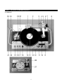
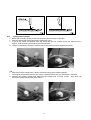
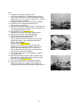
VRX-2000 OWNER`S MANUAL
(preliminary2)
VRX-2000 VINYL CUTTING MACHINE
Congratulations on your purchase of this quality product from Vestax Corporation: the
sensational VRX-2000 Vinyl Cutting Machine.
The VRX-2000 can give you superb results in the making of long-lasting Vinyl records. To
achieve such results, please remember that the mastering process of Vinyl records requires skill
and a basic understanding of complicated audio waveforms.
Cutting Vinyl from a cassette-based multi-track recording or a stereo cassette recorder should
prove to be straight forward, as the frequency response of cassette-based music is not as
intense as that of a CD.
Cutting from professionally mastered CDs that have good equalization and compression should
also give excellent results.
However, recording from some CDs (for example, CDs from home studio set-ups) may provide
difficulties. This is due to the fact that these recordings sometimes have very wide frequency
ranges, and have not been prepared professionally for mass-production or broadcast.
Please study and understand compressors and limiters and how to use equalizers to get the
best result from your VRX-2000.
GENERAL CAUTION
1. This is a product to cut analogue records. Cutting records requires experience and
technique. If you do not learn how to use the VRX-2000 properly, you may not get the best
possible results. Please read this manual carefully. Vestax will not be responsible for the
problems caused by improper use.
2. Please save the original VRX-2000 carton and padding/packing. Always use them for
transportation. If the unit is transported with improper packing and consequently damaged, the
warranty repair will not apply.
3 VRX-2000 is a very high-tech creation. Please use great caution in moving and setting up.
TABLE OF CONTENTS
Section 3 – Basic VRX-2000 Set-up and Components
3.1
Set-up
3.2
Handling
3.3
Cutting Head
3.4
Tracking Arm
3.5
Stylus & Heater Life
3.6
Blank Vinyl
Section 4 – User Registration and Customer Support
Section 5 – Warranty Repair and After-Service
Section 6 - Features
8.1
8.2
8.3
Top Panel
Rear View
Cutting Head Section
Section 9 – VRX-2000 Packing Contents
Section 10 – Assembly and Set-up
10.1
Platter Assembly
10.2
Ioniser Assembly
10.3
Tracking Arm/Counter Weight Assembly
10.4
Cutting Stylus Assembly
10.5
Cutting Head Assembly
Section 11 – Final Adjustments
11.1
Stylus pressure adjustment
Section 12 – Recording Procedures
12-1
Cutting procedures
12-2
Troubleshooting
Section 13 – Playback
Section 14 – Copyright Issues
x
x
Vestax Customer Service Center (c.f. Section 4)
Official Vestax Investigation Form (c.f. Section 4)
Section 3: BASIC VRX-2000 SET-UP AND COMPONENTS
3.1 SET UP
Please place this unit on a solid, stable and horizontal surface. An unstable surface may pick up external
vibrations, and these unwanted sounds will be recorded on the vinyl. Unstable surfaces may also cause platter
rotation fluctuations.
Please avoid sunlight, dust, humidity, and do not place the unit near heating appliances or sources of heat. If
dust gets on the vinyl recording it will cause additional noise on recording sound.
Please do not place the VRX-2000 near loudspeakers, as any sound with enough volume will be recorded on
the vinyl.
Please also never place the unit near TV, radio, or other equipment which generates electric or magnetic fields.
If the unit is located in such a place it may have an effect on the cutting head and you will not achieve the best
result.
3.2 HANDLING
The VRX-2000 is very heavy. It is recommended that extreme care is taken when moving the unit, and that it is
moved by more than one person. If you are going to ship the unit, please use original packing material.
When transporting, please be sure to disassemble the following parts from the main unit:
1. Cutting head
2
2. Play back cartridge
3. Platter
N.B. Please also remove the stylus from the cutting head and place both parts in the original case for
transportation.
3.3 CUTTING HEAD
The cutting head is fragile. Please do not drop or force undue power or pressure, and do not touch any place
other than the stylus holding section. If there is any damage inside the cutting head, the best quality recording
will not be possible.
Please do not place the cutting head in dusty or dirty areas. If dust particles get inside the cutting head, the
head will cease to function properly.
If there is too high a signal applied, the coil may burn or break. In order to avoid such a problem, a limiter circuit
is built-in to the VRX-2000. If you would like to use the unit without internal limiter circuitry, please adjust the
recording levels very carefully, otherwise a high input signal may damage the head.
When you replace the stylus, you will have to assemble and disassemble. Please be careful not to damage the
head on replacement. The cutting head contains a very strong magnet - if steel or other metal is placed near
the cutting head, it will create a very strong magnetic field. Such a damaging strong magnetic field might also
cause a problem with wristwatches, so please remove yours when handling or recording.
3.4 TRACKING ARM
The VRX-2000 tracking arm is another fragile component, and is and very accurately made. Please do not put
pressure on the tracking arm, as it may cause inaccuracies and problems in recording.
If the arm is bent by strong force it will cause the VRX2000 to disfunction totally.
Please also note that the moving parts of the tracking arm require maintenance from time to time.
3.5 STYLUS & HEATER LIFE
x
The life of the cutting stylus is approximately between 200-300 minutes (depending on the cutting pressure
used and the level of stylus heat). Overusing the stylus reduces the quality of recording. You may initially
notice a reduction in the volume of one side (L/R) of the recording as the cutting stylus wears out. Please
replace the stylus regularly.
x
Although the stylus consists of a very hard material, it might be damaged or broken if it is touched or
dropped, mishandled. This will make recording impossible. Please replace the stylus if any of these
instances occur.
x
The heater line (wire) is very thin and fragile, therefore please handle very carefully. If the heater line is cut,
please replace the whole stylus immediately.
x
If too much current is applied to the heater line, the line may burn and break down. Please be very careful
with adjustments of heater current.
x
On assembly of the stylus on the cutting head, please be careful that the heater line does not touch the
vinyl or surrounding parts of the cutting head.
3
3.6 BLANK VINYL
x
Please make sure that the vinyl is perfectly flat when placed on the VRX-2000 for the vinyl cutting
procedure. Vinyl that is not perfectly flat will prevent perfect quality recording.
x
If a bent or warped vinyl is used, the depth or width of the groove will be inconsistent. It will cause a
distortion or needle skipping on playback.
x
On recording, please make sure the surface of the vinyl is clean. Please do not use thinner or methylated
spirits for cleaning.
x
Before recording, please remove the protective sheets on both sides of the blank vinyl. If the sheet is left
on the other side, the vinyl will not be properly secured on the silicone platter mat, which is essential for the
cutting process.
x
The special vinyl for the VRX-2000 has a similar durability of commercial vinyl, but a record cut in improper
circumstances/condition may have less durability than usual.
Section 4: USER REGISTRATION & CUSTOMER SUPPORT
4.1 USER REGISTRATION CARD
x
The official Vestax user registration card is enclosed in the box. Please fill out the card in full and send it to
Vestax customer support in (or nearest to) your country. Vestax will not be able to service or support the
unit if it is not registered. If you have any registration detail changes, please inform your customer service
center immediately.
x
Please contact customer support center with any questions regarding usage or operation. Please fill out the
Investigation Form (found at the back of this manual) and submit to the service center by fax or mail. The
service center will reply to all questions by fax or mail. Please note: some more detailed questions may take
a longer time to respond to.
x
Please see the final page of this manual to find relevant fax numbers and mailing addresses of Vestax
customer service centers.
Section 5: WARRANTY REPAIR AND AFTER-SERVICE
x
Warranty Card: Please keep the warranty card and make sure that it has the date of purchase and store of
purchase.
x
Terms and Conditions of Warranty: The VRX-2000 is covered by warranty for 12 months. However, Vestax
will not honor warranty service if the unit is improperly used, physically damaged, modified by unauthorized
person or damaged by external equipment. The cutting stylus is not covered by warranty.
4
Section 6: FEATURES
x
In the beginning, cutting vinyl records used to require much more equipment and procedures. The VRX2000 allows you to record vinyl in a small space with minimum additional equipment.
x
The VRX-2000 has a newly designed stereo cutting head. It does not require a big power amplifier. It
operates with a built-in power amplifier. The tracking arm also has a new design.
x
The blank disk has a capacity of 14 minutes of recording per side.
x
The VRX-2000 uses a delicate sapphire cutting stylus. The life of the stylus is 200-300 minutes, varying
with the type of usage
.
Section 7: BASIC KNOWLEGDE OF CUTTING MACHINE
7.1 Description of Each Part
x
Cutting arm - the cutting arm consists of two parts: the base and the arm. The base has a mechanism
which moves the arm from the outside to inside of the vinyl as you record. The VRX-2000 uses a DC
motor to rotate the gear and move the head in a constant speed. In addition, the arm can be moved
quickly by using the manual rotation wheel, to move the head toward the specific location on the vinyl
blank where you would like to start recording, or to create a tail.
x
Turntable - consists of a platter, platter weight, silicone mat, and disc holder. The platter weight is very
heavy, facilitating consistent rotation. The silicone mat and disc holder secure the disc on the turntable
solidly, and prevents shifting of the blank disc. The turntable is driven by high torque direct drive AC
motor and generates a very stable rotation to record the music accurately.
x
Cutting Head – the cutting head translates the music signal to the physical movement of the stylus and
cuts the groove on the blank disc. The cutting head of the VRX-2000 uses the same moving coil
technology as top professional cutting machines from the past. The cutting head has 2 magnetic
drivers separated by a 90 degree angle creating a V shape. This layout is optimum for stereo signal
recording with the best possible channel separation, and best balance. The operation of the cutting
head is very similar to that of a loudspeaker – it consists of a coil and a magnet, and the coil moves as
the electric current is applied. The coil is very intricate and fragile – improper handling or overloading
may burn the coil or damage the components. Please be careful not to overload the coil and do not
touch or disassemble the cutting head – damage by improper usage will not be covered by warranty
service.
x
Cutting Stylus – the cutting stylus of the VRX-2000 uses a sapphire tip. The sapphire tip is very
delicate and requires careful handling. The cutting head has a heater line to apply heat to the sapphire
tip while recording. The heater line is very thin and easily damaged; it requires careful handling and
setting up. Please do not use this cutting stylus for any other purpose.
x
Cutting Equalizer – An analogue record is recorded using RIAA equalizer, in order to allow the vinyl to
hold a wide frequency range. The VRX-2000 has an RIAA equalizer built in. This equalizer decreases
the low end and increases the high end for the recording process. On playback, the phono EQ will
automatically adjust to restore the original signal.
5
Section 8: Description of VRX-2000 Components
8.1 Top Panel
6
1.
2.
3.
4.
5.
6.
7.
8.
9.
10.
11.
12.
13.
14.
15.
16.
17.
18.
19.
20.
21.
22.
23.
24.
25.
26.
27.
Ioniser: reduces static build up
Slider arm base : mechanism to move the cutting arm
Tracking arm: arm to hold cutting head and apply correct pressure
Tracking arm weight: adjusts cutting pressure
Slider cam: locks the cutting arm in place
Release lever
Manual rotation wheel: to set the position of the cutting arm in the correct place on the vinyl blank
Cutting head: Vestax proprietary design high quality stereo cutting head
Tracking on/off switch
Recording level volume control: to adjust the level of the incoming signal
Heater current meter: visual display of the level of heat applied to the cutting stylus
Heater current adjustment control: adjusts the level of the heat applied to the cutting stylus.
VU level meters: a display of the input level signal left and right
Vinyl blank holder: secures blank disc to platter
Blank disc
Pitch control adjuster: adjusts pitch of platter +/- 10% , only applicable when quartz lock is disengaged.
Quartz lock switch: locks pitch
Speed select switch: selects the speed – 33 1/3 rpm or 45 rpm. LED displays 45rpm.
Start/stop switch
Playback arm height adjustment screw
Playback arm counter weight
Playback arm headshell
Playback arm armrest
Playback arm
Heavy duty carrying handles
Center spindle on turntable platter
Turntable platter
7
8.2 Rear View
28. Limiter bypass switch: turns the internal compressor limiter on or off. Must always be in on position
unless external compressor limiter devices are used in the cutting process.
29. Input level select switch: adjusts the input gain +4dB/0dB/-10dB
30. Phono level output jacks: standard RCA left/right output jacks for playback
31. On/off power switch
32. AC power cable
33. Ground terminal
34. XLR balanced left/right audio input sockets PIN1 – ground; PIN2 – hot; PIN3 – cold
35. Unbalanced input jacks: standard left/right RCA audio input sockets. N.B. if both XLR and RCA audio
input sockets have equipment connected, the RCA takes precedence and XLR becomes disengaged.
36. Connector cable from cutting head to internal mechanisms.
8
8.3 Cutting Head Section
37.
38.
39.
40.
Cutting stylus holder (A)
Cutting stylus holder (B)
Heater wire terminal
Multipin connector
Section 9: VRX-2000 PACKING CONTENT LIST
Please make sure all following components are included – if any are missing please contact distributor
immediately:
x Cutting head – qty 1 (cutting head screws – qty 2)
x Cutting stylus – qty 3
x Counter weight – qty 1 (screws – qty 2)
x Platter – qty 1
x Platter weights – qty 1
x Silicone mat – qty 1
x Disc holder – qty 1
x Playback holder counter weight – qty 1
x Playback tone-arm headshell – qty 1
x Ioniser – qty 1 (screws – qty 2)
x Stereo RCA cable – qty 1
x Ground cable – qty 1
x Extra fine scale to measure weight of cutting arm – qty 1
x record cleaner (recording cleaning liquid not included – please purchase antistatic record
cleaning liquid – widely available. Please refer to section 3.6 of this manual regarding danger
of using alternate cleaning products).
x Brush – qty 1
x Stylus cleaning liquid – not included – please purchase stylus cleaner.
x Stylus cleaning brush - qty 1
x Screwdriver to secure stylus – qty 1
x Tweezers – qty 1
x Blank vinyl disc – qty 6
x Vinyl record labels – qty 12
x Owners manual and related vrx-2000 documents – qty 1
9
Section 10: ASSEMBLY AND SET-UP
10.1
Platter assembly
1. Insert platter to center spindle
2. Put platter weight on platter
3. Put silicone mat on top of platter weight.
Caution: make sure silicone mat is dust-free
4. Remove the protective sheet of blank disc on both sides, and place blank disc on silicone mat; push the
blank disc down on silicone mat using a lint-free cloth or the included record cleaner. Apply sufficient
pressure to firmly secure the vinyl blank to the silicone mat.
5. Screw disc holder and secure blank.
x If the blank disc is not dust-free, it may create skipping or noise problems. Ensure your blank is
perfectly clean.
x If the blank disc is not secured to silicone mat, slipping may occur which will render your final
cut unusable.
Disc holder
Blank vinyl disc
Silicone mat
Platter weights
Platter
Center spindle
10.2 Ioniser Assembly
Secure ioniser with 2 screws as per picture below.
(Figure 10.2-A)
10.3 Tracking arm/counter weight assembly
Assemble counter weight on the rear of tracking arm.
(Figure 10.3-A)
FIG10.2-A
FIG10.3-A
10
10.4 Cutting stylus assembly
Cutting stylus components:
x Stylus tip – highest quality sapphire
x Heater line – to heat stylus tip to 40-60 degrees centigrade
x Lifetime of stylus – 200-300 minutes
N.B.
Please be careful of sapphire tip due to its delicate nature.
The lifetime varies, depending on recording conditions,
the applied stylus heat and pressure. Different atmospheric
conditions will dictate different levels of stylus pressure
and heat. Please find optimum conditions for the VRX-2000
to maximize the life of the cutting stylus.
1. Loosen the screw on the stylus holder
2. Carefully insert cutting stylus into stylus receptor.
The shaft of the cutting stylus is half circle, or D shaped.
Please ensure that this is placed into the cutting stylus
receptor correctly.
3. Holding the stylus tip gently, alternatively tighten the
2 stylus screws one rotation each until each of the
2 screws secure the stylus shaft. Do not over tighten
and do not tighten screw a and then screw b independently.
Please make sure that the stylus shaft and cutting stylus
are correctly aligned with the receptor. This is why
the 2 screws must be tightened slowly and alternatively.
Please refer (Figure 10.4-C) (correct stylus installation)
and (Figure 10.4-D) (incorrect stylus installation).
N.B.
The cutting stylus must have an angle of approx 15 degrees
to the surface of the vinyl blank. If the cutting result is not
satisfactory (L&R side not even), please repeat steps 1-3
above using the 2 screws that hold the stylus shaft to achieve
the angle of approximately 15 degrees.
Please refer (Figure 10.4-F) and (Figure10.4-G).
4. Connect the two heater wires to the heater wire terminal. There is no positive or negative polarity here,
so there is no requirement for the wires to be attached in a particular order. To attach the wire to the
terminal, push down, insert wire and release. N.B. please make sure there is no slack in the heating
wire and it totally clears the surface of the vinyl blank.
FIG10.4-C
11
FIG10.4-D
FIG10.4-F
FIG10.4-G
10.5
Cutting head assembly
x Before the assembly, please ensure that the cutting head is always to the right
x Please assemble the cutting head after installing the stylus.
1. If you lift the cutting arm release lever, the cutting arm lifts up. Please ensure the release lever is
locked. Slide the cutting head into the arm from the front.
2. Using the screwdriver, secure the cutting head on the cutting arm with supplied two screws.
N.B.
x Please ensure the cutting head is totally secured or cutting result will be imperfect.
x The magnet on the cutting head is very strong – therefore make sure your wristwatch is removed.
3. Connect the multipin cutting head cable into the cutting head, ensuring it locks. N.B. when you
disconnect, gently pull back the metal sheath.
12
Section 11: FINAL ADJUSTMENTS
11.10000Stylus pressure adjustment
x Ensure the tracking arm is always to the right.
1. Attach the supplied extra fine weight scale
(Figure 11.1-A). Lock the release lever in
horizontal position.
2. Holding the scale by the top, make the cutting
arm horizontal, and adjust the counter weight
until the scale measures.
FIG11.1-A
Condition
Kind ofblankdisc
rpm
Harm o disc
33
Harm o disc
45
Lacquerdisc
33,45
Stylus pressure [N] Currentheater[m A]
0.45 `
0.50
0.50 `
0.55
0.30 `
0.35
200
500
300
Section 12: RECORDING PROCEDURES
12.1
Cutting procedures
1. Remove the protective sheet of disc on both sides and secure.
2. Secure clean blank disc
3. Select speed N.B. recommended speed for
easiest cutting is 45rpm
4. Adjust pitch
5. Push start button
6. Turn Ioniser on using on/off switch on rear
of Ioniser mechanism.
Select “high”. Please refer (Figure12.1-A).
7. Rotate the slider cam and release lock of the
cutting arm. See (Figure 12.1-B).
8. Set the input level control to minimum
and heater control adjustment to minimum.
9. Turn tracking on/off switch to “on” N.B.
if the arm starts moving, the lock is in
the incorrect position. Please ensure
lock is released before proceeding.
10. To achieve the desired heat of the cutting
stylus wait 2-4 minutes.
11. Begin play back of the recording source
and increase the input level control, making
sure that the level does not exceed 0db.
12. Peaks of the source material must never exceed 0db.
13
FIG12.1A
FIG12.1B
N.B.
x Too high an input level will burn the coil
x If the source material has an extremely wide dynamic
range, minimum levels may not be sufficient to achieve
the desired result. In this case, use of Vestax SL-201mkii
compressor-limiter is required.
13. Using anti-static spray, clean the vinyl blank perfectly.
14. Set external music source at the desired start
point in pause or stop mode
15. Lock the cutting arm by rotating the cam. Manually move
the arm by using manual rotation wheel and position arm
above appropriate point on blank.
16. Hold the brush as per (Figure 12.1-C).
Place the release lever in the down position gently.
17. Start the music source and recording begins!
18. Using the brush gently take the excess vinyl
off-cuts away form the cutting stylus.
Try to make the vinyl off-cuts wind around the center
spindle (disc holder). This will reduce the amount
of brush action required.
Please refer to (Figure 12.1-D).
Caution: If the vinyl off-cuts builds up around the
cutting stylus you will not get a perfect cutting result.
Please continually check the stylus. In case the
off-cuts get stuck around the stylus use the tweezers
to remove the build up very carefully.
19. Put the input level down as you would with a fade out
on an audio mixer.
20. Move the release lever gently to the up position, then
unlock the cam. Move the arm all the way to the right
away from the vinyl(Figure 12.1-E).
21. Push Start/Stop button to stop the platter rotation.
22. Check the surface of the vinyl and check there are
no off-cuts on the vinyl. If there is any residual, use
the record cleaner and cleaning solution to clean the vinyl.
FIG12.1C
FIG12.1D
FIG12.1E
14
12.2
1
2
3
4
5
Troubleshooting
Use a test blank to check before going to a final cut.
If you have any problems check stylus heat, stylus
pressure, stylus angle, static build up, cleanliness
of vinyl and any external signal devices you may be
using.
If you are still experiencing problems, use a test
blank and record with no input signal.
The vinyl off-cut should be straight(a).
If it is showing big curls the angle of the stylus
should be adjusted, or the stylus should be replaced(b)(e).
If the off-cuts are straight, but very thin,
increase the stylus pressure(c).
If it is curly and too thin, the stylus temperature is too low(d).
If the off-cut breaks as you record,
the stylus temperature is too high(f).
Cutting in this way requires experience.
Please take your time, and be patient, using test blanks
to ensure you have the heat, the pressure and the angle
of the stylus all correct.
If there is noise on the playback there are two main
reasons. Firstly, if there is random noise or “white
noise” the stylus tip may be broken or the disc is
not clean enough. Secondly, if there is static noise
apply ant static spay and ensure the Ioniser is turned on.
Section 13: PLAYBACK
Before playing back your vinyl cut, please ensure the following:
- Make sure the surface of the vinyl is totally clean and no off-cuts remain.
- Make sure the recording arm is all the way to the right and locked.
- Turn the Ioniser off
15
Section 14: COPYRIGHT ISSUES
VESTAX takes no responsibility for copyright infringement. Copyright laws are different in many countries and
we strongly suggest that you get all the copyright information before duplicating any artists’ recordings. Artists
deserve to be paid for public performance of their works, and VESTAX supports this stance.
You can check copyright laws at the following web sites:
- http://cybeat.com.au – broadcasters and music copyright
- http://webcom.com/~music – music copyright site
- http://mpa.org – guide to copyright searching
- http://cyberplayground.net – music & copyright law sites of information
- http://mpaonline.org.uk – Music Publishers Association – copyright law
VESTAX CUSTOMER SERVICE CENTRES
Vestax Japan (Head Office)
1-18-6 Wakabayashi
Setagaya-ku
Tokyo 154-0023 Japan
Fax: (International Code, Country code) + 81-(0)3-3412-7013
Website: http://www.vestax.co.jp
Email: [email protected]
Vestax Europe Ltd
Unit 5 Riverwey Industrial Park
Alton, Hampshire GU34 2QL
Fax: (International Code, Country code) + 44-1420-80040
N.B. If you are unsure where to send registrations in your country, please contact Vestax Head Office in Japan.
INVESTIGATION FORM
Insert newly created Investigation Form Here
N.B. make sure the Vestax registration card now includes a section for email addresses and websites of
the new registered user for our database purposes and more efficient contact with the user.
16