1
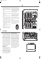
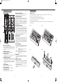
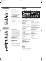
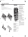
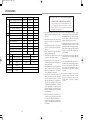
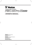
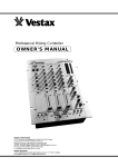
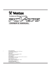
PMC-CX/E 04.4.26 10:16 AM ページ 1
OWNER'S MANUAL
Vestax Corporation
1-18-6 Wakabayashi, Setagaya-ku, Tokyo 154-0023 Japan
Phone 03-3412-7011 Fax 03-3412-7013
Web : www.vestax.com
Vestax (Europe) Ltd.
Unit 5 Riverwey Industrial Park Alton Hampshire GU34 2QL England, U.K.
Phone (0)1420-83000 Fax (0)1420-80040
Web : www.vestax.co.uk
Vestax Europe Technical Support
Rheinstr.213 D-53332 Bornheim Germany
Phone 49(0)2222-95-23-72 Fax 49(0)2222-95-23-74
Vestax Corporation
APR.2004 PMC-CX E q
PMC-CX/E 04.4.26 10:16 AM ページ 3
CONGRATULATIONS!
Thank you for purchasing the Vestax PMC-CX Professional Mixing Controller. We suggest that
you read through this owner's manual thoroughly so that you may enjoy the full use of this
product safety and in the knowledge of all its special features and suitably applications.
CONTENTS
C A U T I O N
IMPORTANT SAFEGUARDS
F E AT U R E S
F U N C T I O N
PROGRAM SECTION
MASTER SECTION
MIC/LINE SECTION
MONITOR SECTION
R E A R PA N E L
HOW TO CHANGE THE FADER UNIT
BLOCK DIAGRAM
SPECIFICATIONS
2
3
4
5
6
7
8
8
9
10
12
14
CAUTION
RISK OF ELECTRIC SHOCK DO NOT OPEN
CAUTl0N:TO REDUCE THE RlSK OF ELECTRlC SHOCK
DO NOT REMOVE COVER(OR BACK)
NO USER-SERVICEABLE PARTS INSIDE
REFER SERVlCING T0 QUALIFIED SERVlCE PERSONNEL
The lightning flash with arrowhead symbol,within an equilateral triangle,is intended to
alert the user to the presence of uninsulated“dangerous voltage”within the product's
enclosure that may be of sufficient magnitude to consitute a risk of electric shock to persons.
The exclamation point within an equilateral triangle is intended to alert the user to the presence
of important operating and maintenance(servicing)instructions in the literature accompanying
the appliance.
T0 REDUCE THE RISK 0F FIRE 0R ELECTRlC SHOCK,DO NOT
EXPOSE THIS APPLIANCE T0 RAIN 0R M0ISTURE.
2
15
PMC-CX/E 04.4.26 10:16 AM ページ 5
SIZE
16. Replacement Parts-When replacement parts are
required, be sure the service technician has used
replacement parts specified by the manufacturer
or have the same characterristics as the original
parts. Unauthorized substitutions may result in
fire, electric shock or other hazards.
17. Safety Check-Upon completion of any service or
repairs to product, ask the service technician to
perfrom sefety checks to determine that the
product is in proper operating condition.
18. Carts and Stands-The appliance should be used
only with a cart stand that is recommended by
manufacturer.
19. An appliance and cart combination should be
moved with care. Quick stops, excessive force,
and uneven surfaces may cause the appliance
and cart combination to overturn.
15. Damage Requiring Service-Unplug this product
from the wall outlet and refer servicing to
qualified service personnel under the following
conditions:
a. When the power-supply cord or plug is
damaged.
b. If liquid has been spilled or objects have fallen
into the product.
c. If the product has been exposed to rain or
water.
d. If the product dose not operate normally by
following the operating instructions. Adjust
only those controls that are coverd by the
operating instructions as an improper
adjustment of other, controls may result in
damage and will often require extensive work
by a qualified technician to restore the product
to its normal operation.
e. If the product has been dropped or cabinet has
been damaged.
f. When the product exhibits a distinct change in
perfromance-this indicates need for service.
FEATURES
・The PMC-CX was built to give Carl Cox what he
3 Band Isolators on each PGM
always wanted. A solid, reliable, high quality mixer, that ・The PMC-CX features a superb 3-band isolator on
has enough features to allow him to give 110% during
each PGM. The isolators on the PMC-CX offer
every performance, every time. Specifically the
infinity cut (100%) with a boost of +4dB. This means
PMC-CX includes a number of features that will
that you can cut out 100% of the Low, Mid and Highs or
definitely give you a lot more creative freedom whilst "in
boost them by 4dB. In addition to being able to make
the mix". Such as 3 band isolators & great high, low and
adjustments using the isolator volume knobs, the
notch filters on each PGM, a master out isolator
isolator feature is selectable to either on or off. When
section with anti phase and a matrix input control so you
used in tandem with the Matrix Input Assign feature a
can mix in and out of inputs quickly and easily.
user can set up the isolator levels for one track across all
Regardless of your skill level you will find the CX
three PGMs and then use the input faders or cross
enjoyable and easy to use because of its layout and
fader to control what is heard (PGM1 = Low cut,
great features, but you will fall in love with it because of
PGM2 = Mid cut & PGM3 = high cut). By using the
its high quality components and design.
system this way there is more precise control and a lot
Matrix Input Assign
more room for dynamic (physical) changes in the
・The matrix input assign on the PMC-CX is an
frequency structure of a particular track.
innovative and useful feature that allows you to select or
route any input source on/to any channel. On the
PMC-CX you are able to route inputs connected on one
channel to any other channel. It is also possible to
route the one input signal across all three PGMs with
this feature, for more information read below.
4
13
PMC-CX/E 04.4.26 10:16 AM ページ 7
CROSS FADER
PROGRAM SECTION
3
2
1
4
5
6
i ISOLATOR ON/OFF SWITCH
7
When set to "OFF", a full range signal is transmitted
regardless of the position of any isolator controls.
o HI PASS FILTER SWITCH
On each PGM is a Hi Pass Filter Switch. Pressing this
switch activates the high pass filter and when on the
indicator LED will illuminate. The cut off frequencies
for this filter can be adjusted by the SWEEP volume
rotary dial !1. If this switch is pressed simultaneously
with the Low Pass Filter switch the resulting effect is a
Notch Pass Filter.
!0 LOW PASS FILTER SWITCH
8
Change to "CF-50"
q Remove the fader knob and 4 screws which fix the crossfader panel, and the carefully remove the panel. (See fig-e)
w Remove the 2 screws affixing the crossfader. (See fig-f)
e Carefully remove the multi-cable connector from the fader unit. (See fig-g)
r Remove the fader knob and the fader panel of the new CF-50. (See fig-h)
t Attach the fader panel to the new CF-50.
y Replace the fader unit making sure to that the connector wires are securely fastened before carefully positioning the fader unit
and affixing screws.
fig-e
fig-f
fig-g
fig-h
On each PGM is a LOW pass filter switch. Pressing this
switch activates the low pass filter for that PGM. When
on the indicator LED will be illuminated and this filter
will remove sound frequencies below the cut off point.
The cut off point can be adjusted by using the SWEEP
volume rotary dial !1. If this switch is pressed
simultaneously with the High Pass Filter switch the
resulting effect is a Notch Pass Filter.
12
!1 SWEEP VOLUME
9
10
This rotary dial is used to adjust the filter cut off points on
each PGM. A rotation to the left will result in a movement
away from the High frequencies towards the Low
frequencies. Vice versa a movement to the right will result
in a movement away from the Low frequencies towards the
High frequencies.
14 13 11
!2 C.F. ASSIGN SWITCH
q PHONO / LINE SELECTOR
Assigns the signals from each of the PGM channels to either
side of the crossfader or to MASRER OUT. There are three
positions;
A ⋯⋯⋯⋯The PGM is sent to the "A" position or left
position of the crossfader.
MASTER ⋯The PGM is sent directly to the master out.
B ⋯⋯⋯⋯The PGM is sent to the "B" position or right
side of the crossfader.
Selects the signal (PHONO or LINE) to be sent to each
INPUT. All phono inputs are RIAA equalized. Connect
the output of a CD player, MD player, and tape deck to
the line input.
w INPUT ASSIGN SWITCH
Selects the input to be sent to each PGM channel.
e PGM TRIM VOLUME
!3 CUE SWITCH
Adjusts the input level of each PGM channel. PGM
LEVEL METER to indicate at about 0dB.
Sends a signal from each PGM to the monitor section for
headphone monitoring. When switch is on, an indicator
lights up.
r PGM BALANCE VOLUME
Adjusts the stereo balance for each PGM channel. Can be used
!4 INPUT LEVEL VOLUME
for adjusting the unbalanced stereo image. Clockwise rotation
Adjusts the Input level of each program. Typically this
from center position increases the volume of R over L channel.
fader is set to a position of 7-8. This fader is user
A counter clockwise rotation increases the volume of L
replaceable and may be changed easily by following this
channel over R.
users guide's instructions carefully. See "HOW TO
t PGM ISOLATOR HI
CHANGE THE FADER UNIT".
Adjusts the HI frequency level of each PGM.
*Replace this fader with a Vestax IF-500 replacement
inputfader.
y PGM ISOLATOR MID
Adjusts the MID frequency level of each PGM.
u PGM ISOLATOR LOW
Adjusts the LOW frequency level of each PGM.
6
11
PMC-CX/E 04.4.26 10:16 AM ページ 9
HOW TO CHANGE THE FADER UNIT
MIC / LINE SECTION
REAR PANEL
@9 SUB MIC LEVEL VOLUME
49
50
46
39
45 44
Adjusts the input level of the SUB MIC input.
#0 MAIN MIC / SUB LINE SELECTOR
Selects between MAIN MIC and SUB LINE input.
51
#1 MIC / LINE EQ VOLUME
29
Adjusts the HI and LOW frequencies for the signal
chosen by MAIN MIC / SUB LINE SELECTOR.
38
52
#2 MIC / LINE LEVEL VOLUME
30
Adjusts the input level of the MAIN MIC or SUB LINE
input.
48
47
43
42
41
40
#3 MIC / LINE CUE SWITCH
31
Sends the signal from the MIC or LINE channel to the
monitor section for headphone monitoring. When switch is
on, an indicator lights up.
32
#8 MAIN/SUB MIC JACK
$7 MASTER OUT 1/2 JACK
[MAIN MIC: XLR JACK (BALANCED), SUB MIC:
PHONE JACK (UNBALANCED)]
Input jack for MIC.
[1/4' PHONE JACK (UNBALANCED), XLR JACK
(BALANCED]
Connect to the input on a power amplifier. These jacks are
Phone type for consumer applications. This mixer has two
sets of MASTER OUT jacks so that the each output level
can be set separately. Therefore, the MASTER OUT can
be used for main output or sub output IE. One for the
main area and the other for entrance.
#9 LINE INPUT JACK
33
[LINE: RCA PIN JACK, SUB LINE: 1/4' PHONE JACK
(UNBALANCED)]
Input connectors for line level equipment such as CD
players, CD-R/RW players, MD players, tape decks,
DVD players, DAT and VTR etc.
$8 MASTER OUT LEVEL SELECT SWITCH [-10/0dB]
Select the attenuation level for the BOOTH OUT.
$0 PHONO INPUT JACK
MONITOR SECTION
#4 SPLIT / STEREO SELECTOR
When this switch is set to "SPLIT", the master signal is
always heard through the right ear-cup of the headphone.
The signal selected by each CUE SWITCH will be heard
in the left ear-cup. This enables both programs to be
monitored simultaneously, thus assisting in beat mixing.
When this switch is set to "STEREO" no master output is
heard in the headphones, and only the signal selected by
each CUE SWITCH will be heard in both ear-cups.
34
35
36
#5 HEADPHONE EQ VOLUME
Adjusts the HI and LOW frequencies for Headphone
monitoring.
#6 HEADPHONE LEVEL VOLUME
Adjusts the headphone monitor level.
#7 PHONES JACK
Use this jack to connect headphones. Headphones with
an impedance of 8ohm to 600ohm can be used on this
unit.
*For best sound quality Vestax recommends using
Headphones with 150ohm impedance.
37
$9 MASTER LOOP SEND JACK
[1/4' PHONE JACK]
[RCA PIN JACK]
Input jacks for turntables. Connect turntables equipped
with MM (pick up) cartridge.
Connects the input terminal of an external effector.
(Delay, Reverb, etc.)
$1 GND TERMINAL
Connect this terminal to the ground lead of the turntable. %0 MASTER LOOP RCV JACK
This will help to reduce unnecessary noise.
[1/4' PHONE JACK]
Connects the output terminal of an external effector.
$2 INPUT LEVEL SELECT SWITCH[-10/0dB]
Select the attenuation level for the input.
%1 POWER SWITCH
Power on/off.
$3 BOOTH OUT JACK
[1/4' PHONE JACK (UNBALANCED), XLR JACK %2 AC IN JACK
(BALANCED)]
Connect the Vestax AC-20 , AC adaptor.
Connects to the DJ booth monitors. This signal is identical to the
HEADPHONE OUT signal.
$4 BOOTH OUT LEVEL SELECT SWITCH
Select the attenuation level for the BOOTH OUT.
$5 MIC MONITOR IN/OUT SWITCH
Select whether the signal connected to MAIN/SUB MIC
is mixed with the signal outputted from MASTER
OUT1/2.
$6 REC OUT JACK
[RCA PIN JACK]
Connects to the input jack of a recording device IE, tape
recorder, MD, DAT, etc. The output level of this jack is
fixed and does not change with the MASTER LEVEL.
8
9
PMC-CX/E 04.4.26 10:16 AM ページ 11
HOW TO CHANGE THE FADER UNIT
INPUT FADER
MASTER SECTION
@0 BOOTH MONITOR EQ VOLUME
Change to "IF-500"
Adjusts the HI/MID/LOW frequencies for the BOOTH
OUT.
q Remove the fader knob. (See fig-a)
w Remove the 4 screws which fix the input fader panel to the mixer. (See fig-b)
e Remove the 2 screws which fix the input fader. (See fig-c)
@1 BOOTH MONITOR LEVEL VOLUME
Adjusts the output level of BOOTH MONITOR.
r Remove the input fader, and carefully remove the multi-cable connecter from the fader unit. (See fig-d)
t Replace the fader unit making sure to that the connector wires are securely fastened before carefully positioning the fader unit
and affixing with screws.
@2 BOOTH MONITOR MUTE SWITCH
This switch mute the signal being sent to the BOOTH
OUT.
18
@3 ANTI PHASE ON / OFF SWITCH
fig-a
This switch is used to activate an antiphase effect on the
Master Isolator Section. Essentially, an antiphase flips the
isolator curve upside down on both the low and mid frequency
ranges, which thereby creates a reverb type effect on the signal
being outputted.
19
fig-b
16
17
@4 MASTER ISOLATOR HI
15
This rotary dial section can be used to isolate the Hi
frequencies on any MASTER SECTION input signal.
21
22
@5 MASTER ISOLATOR MID
20
This rotary dial section can be used to isolate Mid frequencies
on any MASTER SECTION input signal.
27
@6 MASTER ISOLATOR LOW
23
This rotary dial section can be used to boost the Low
frequencies on any MASTER SECTION input signal.
24
@7 ISOLATOR ON / OFF SWITCH
25
This switch is used to turn the Master Isolator Volume Section
either on or off. When set to the "OFF" position the full range
of input signal being sent to the MASTER section will be
heard regardless of the position of the Master Isolator Volume
rotary dials.
26
@8 CROSS FADER
28
fig-c
Mixes the signals assigned by the CROSSFADER ASSIGN
SWITCHES to either side of the crossfader. When the
crossfader is set in the center position, both the left and right
signals will be heard. This fader is user replaceable and may be
changed easily by following this user guide's instructions
carefully. See "HOW TO CHANGE THE FADER UNIT".
*Replace this fader with a Vestax CF-50 replacement
inputfader.
fig-d
!5 MASTER LEVEL VOLUME
Adjusts the signal level outputs from MASTER OUT1/2
JACKS $7 on the rear panel.
!6 MASTER CUE SWITCH
Used to send the signal from MASTER OUT1/2 to the
monitor section for headphone monitoring. When switch
is on, an indicator lights up.
!7 CF CURVE VOLUME
djusts the crossfader curve. A clockwise rotation gives a
sleep crossfade which is good for scratching and cutting.
whereas a counter clockwise rotation gives a gentle
crossfade, good for long running mixes.
!8 MASTER LEVEL METER
The VU analog level meters indicate the L and R outputs.
!9 PGM LEVEL METER
The LED bar level meters indicate the PGM channel.
10
7
PMC-CX/E 04.4.26 10:16 AM ページ 13
BLOCKDIAGRAM
High Pass, Low Pass & Notch Filter (effect) on each PGM
Suitable for all DJs
・On the PMC-CX each PGM has a filter effect section ・With more than enough creative room for even the
with a high pass, low pass and (when pressed
most experimental DJs the PMC-CX is truly suitable for
together) a notch filter. These filters are used to alter the
almost any type of DJ. In addition to the features
frequency response of a given audio signal in either an
above, there are a number of other features that make
extreme or subtle manner
this mixer very user friendly whether you are a hobby
DJ, a professional touring DJ or a club install user.
Master Isolator with Antiphase
The large analogue VU meters allow you to easily
・On the master output of the PMC-CX we have
view the output level and safely stay within a suitable
incorporated one of Carl's favorite Vestax units, the
range. The large open design of this mixer means
DCR-1200, a 3 Band Isolator with Antiphase. Using
that you can accurately and quickly get to all features in
the master isolator allows finer control over the cut
any environment (dark or light) even if you are
and or boost of the low, mid and high ranges when the
endowed with big fingers. For install users the booth,
effect is set to on. Obviously when set to off, only the
master out and input levels can be attenuated keeping
PGM features will effect the sound. When combined
expensive sounds systems safe from over zealous
with antiphase it is possible to create sensational
users. For those users who need scratch capabilities (Hip
reverb like effects over the whole mix. Antiphase
Hop, drum & bass etc) the cross fader (VCA PCV
flips the isolator curve upside down on both the low and
type fader) curve is adjustable from a steep to gentle
mid frequency ranges (there is no need for a high
slope. The booth output section has its own 3-Band EQ
antiphase as it is out of our human hearing range).
and the headphone section has its own 2-Band EQ.
Add in the MIC features and this mixer is perfect for
Mobile DJs who desire the quality of this top line
model from Vestax. In all, the PMC-CX was
designed by a great mixer to be used as a great mixer.
FUNCTIONS
TOP PANEL
MIC/LINE SECTION
PROGRAM SECTION
MONITOR SECTION
12
5
MASTER SECTION
PMC-CX/E 04.4.26 10:16 AM ページ 15
SPECIFICATION
IMPORTANT SAFEGUARDS
NOMINAL INPUT
MAXIMUM INPUT
IMPEDANCE
MAIN MIC(XLR FEMALE 2PIN HOT BALANCED)
-50dBv
-35dBv
1.0K
-50.
SUB MIC (φ6.3 PHONE JACK UNBALANCED)
-50dBv
-35dBv
1.0K
-46.
PHONO 1∼4 L /R (RCA PIN JACK)
-46dBv
-35dBv
59KΩ
+14d
LINE 1∼4 SUB L /R (RCA PIN JACK)
0dBv
+12dB
35KΩ
0dBv
MASTER LOOP RCV(φ6.3 PHONE JACK UNBALANCED)
0dBv
+12dB
50KΩ
RATED OUTPUT
MAXIMUM OUTPUT
IMPEDANCE
MASTER1/2 L /R(XLR MALE 2PIN HOT BALANCED)
+4dBv
+22dB
600Ωover/150Ω 0dBv
MASTER1/2 L /R(φ6.3 PHONE JACK UNBALANCED)
0dB,-10dB
+22dB
10KΩover/220Ω +4dB
INPUT
SECTION
REC OUT(RCA PIN JACK)
-10dB
+12dB
SECTION
BOOTH L/R(XLR MALE 2PIN HOT BALANCED)
+4dBv
+22dB
600Ωover/150Ω 0dBv
BOOTH L/R(φ6.3 PHONE JACK UNBALANCED)
0dB,-10dB
+22dB
10KΩover/220Ω 0dBv
+22dB
10KΩover/220Ω 0dB
MASTER LOOP SEND(φ6.3 PHONE JACK UNBALANCED)
HEADPHONE(φ6.3 PHONE JACK)
FREQUENCY MIC
RESPONSE
S/N RATIO
190mW
10KΩ
0dBv
OUTPUT
8Ωover/47Ω
30Hz∼20KHz ±3dB
POWER SUPPLY
AC20V
LINE
30Hz∼20KHz ±1.5dB
POWER REQUIREMENT
45W
MIC
>60dB
DIMENSION(W×H×D)
LINE
>75dB
WEIGHT
CROSSFADER CROSSTALK
>80dB
CHANNEL CROSSTALK
>65dB
FADER ATTENUATION
>80dB
14
30HzdB
B
482×122×308
(mm)A
7.0kg
m)
READ BEFORE OPERATING EQUIPMENT
This product was designed and manufactured to meet
strict quality and safety standards. There are, however,
some installation and operation precautions which you
should be particularly aware of.
1. Read instructions-All the safety and operating
instructions should be read before the appliance
is operated.
2. Retain instructions-The safety and operating
instructions should be retained for future
reference.
3. Heed Warnings-All warnings on the appliance
and in the operating instructions should be
adhered to.
4. Follow Instructions-All operating and use
instructions should be followed.
5. Cleaning-Do not use liquid cleaners or aerosol
cleaners. Use a damp cloth for cleaning.
6. Attachments-Do not use attachments not
recommended by the product manufacturer as
they may cause hazards.
7. Water and Moisture-Do not use this product near
water-for example, near a dath tub, wash bowl,
kitchen sink, or laundry tub, in a wet basement,
or near a swimming pool, and the like.
8. Accessories-Do not place this product on an
unstable cart, stand, tripod, or table. The product
may fall, causing serious injury to a child or
adult, and serious damage to the appliance. Use
only with a cart,. stand, tripod, bracket, or table
recommended by the manufacturer, or sold with
product. Any mounting of the appliance should
follow the manufacturer's instructions, and
sholud use a mounting accessory recommended
by the manufacturer.
9. This product should never be placed near or over
a radiator or heat register. This product should
not be placed in a built-in installation such as a
bookcase or rack unless proper ventilation is
provided or the manufacturer's instructions have
been adhered to.
10. Power sources-This product should be operated
only from the type of power source indicated on
the marking label. If you are not sure of the type
of power supply to your home, consult your
appliance dealer or local power company.
11. Lightning-For added protection for this product
during lightning storm, or when it is left
unattended and unused for long periods of time,
unplug it from the wall outlet. This will prevent
damage to the product due to lightning and
power-line surges.
12. Overloading-Do not overload wall outlets and
extension cords as this can result in a risk of fire
or electric shock.
13. Object and Liquid Entry-Never push objects of
any kind into this product through openings as
they may touch dangerous voltage points or
short-out parts that could result in a fire or
electric shock. Never spill liquid of any kind on
the product.
14. Servicing-Do not attempt to service product
yourself as opening or removing covers may
expose you to dangerrous voltage or other
hazards. Refer all servicing to qualified
sersonnel.
3