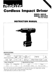
1
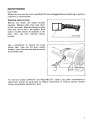
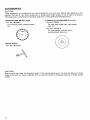
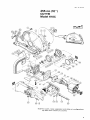
Anale
u - Cutter
-
-
-
~
255 mm (10”) MODEL 4110C
INSTRUCTION MANUAL
DOUBLE
INSULATION
SPECIFICAT10 NS
Wheel
diameter
Max.
cutting capacity
255 mm (10”)
75 mm (3”)
AMPS
(115 v1
No load speed
AClDC
15 A
3r500
Overall
length
Net
weight
supply cord
620”
(24.318“)
9 kg
(19.8 Ibs)
2.5 m
(8.2 ft.)
Power
IMPORTANT
SAFETY INSTRUCTIONS
(For All Tools)
WARNING: WHEN USING ELECTRIC TOOLS, BASIC SAFETY
PRECAUTIONS SHOULD ALWAYS BE FOLLOWED TO REDUCE
THE RISK OF FIRE, ELECTRIC SHOCK, AND PERSONAL
INJURY, INCLUDING THE FOLLOWING:
READ ALL INSTRUCTIONS.
~~~
~~
1. KEEP WORK AREA CLEAN. Cluttered areas and benches invite injuries.
2. CONSIDER WORK AREA ENVIRONMENT. Don't use power tools in damp
or wet locations. Keep work area well lit. Don't expose power tools t o rain.
Don't use tool in presence of flammable liquids or gases.
3. KEEP CHILDREN AWAY. All visitors should be kept away from work area.
Don't let visitors contact tool or extension cord.
4. STORE IDLE TOOLS. When not in use, tools should be stored in dry, and high
or locked-up place - out of reach of children.
5. DON'T FORCE TOOL. It will do the job better and safer at the rate for which
it was intended.
6. USE RIGHT TOOL. Don't force small tool or attachment t o do the job of a
heavy-duty tool. Don't use tool for purpose not intended; for example, don't
use circular saw for cutting tree limbs or logs.
7. DRESS PROPERLY. Don't wear loose clothing or jewelry. They can be caught
in moving parts. Rubber gloves and non-skid footwear are recommended
when working outdoors. Wear protective hair covering t o contain long hair.
8. USE SAFETY GLASSES. Also use face or dust mask if cutting operation is
dusty.
9. DON'T ABUSE CORD. Never carry tool by cord or yank it t o disconnect from
receptacle. Keep cord from heat, oil, and sharp edges.
IO. SECURE WORK. Use clamps or a vise to hold work. It's safer than using
your hand and it frees both hands to operate tool.
11. DON'T OVERREACH. Keep proper footing and balance at all times.
12. MAINTAIN TOOLS WITH CARE. Keep tools sharp and clean for better and
safer performance. Follow instructions for lubricating and changing accessories. Inspect tool cords periodically and if damaged, have repaired by authorized service facility. Inspect extension cords periodically and replace if
damaged. Keep handles dry, clean, and free from oil and grease.
13. DISCONNECT TOOLS. When not in use, before servicing, and when changing accessories, such as blades, bits, cutters.
2
14. REMOVE ADJUSTING KEYS AND WRENCHES. Form habit of checking to
see that keys and adjusting wrenches are removed from tool before turning
it on.
15. AVOID UNINTENTIONAL STARTING. Don't carry tool with finger on switch.
Be sure switch is OFF when plugging in.
16. EXTENSION CORDS. Make sure your extension cord is in good condition.
When using an extension cord, be sure to use one heavy enough to carry
the current your product will draw. An undersized cord will cause a drop
in line voltage resulting in loss of power and overheating. Table 1 shows the
correct size to use depending on cord length and nameplate ampere rating.
If in doubt, use the next heavier gage. The smaller the gage number, the
heavier the cord.
TABLE 1 MINIMUM GAGE FOR CORD SETS
I
Total Length of Cord in Feet
0 - 25
26 - 50
Ampere Rating
More
Not More
Than
Than
0
6
10
12
-
6
-
10
12
16
-
51 - 100
101 - 150
A W G
18
18
16
14
16
16
16
12
;:
I
14
12
14
12
Not Recommended
17. OUTDOOR USE EXTENSION CORDS. When tool is used outdoors, use only
extension cords intended for use outdoors and so marked.
18. STAY ALERT. Watch what you are doing, use common sense. Don't operate
tool when you are tired.
19. CHECK DAMAGED PARTS. Before further use of the tool, a guard or other
part that is damaged should be carefully checked to determine that it will
operate properly and perform its intended function. Check for alignment of
moving parts, binding of moving parts, breakage of parts, mounting, and any
other conditions that may affect its operation. A guard or other part that
is damaged should be properly repaired or replaced by an authorized service center unless otherwise indicated elsewhere in this instruction manual.
Have defective switches replaced by authorized service center. Don't use
tool if switch does not turn it on and off.
20. GUARD AGAINST ELECTRIC SHOCK. Prevent body contact with grounded
surfaces. For example; pipes, radiators, ranges, refrigerator enclosures.
21. REPLACEMENT PARTS. When servicing, use only identical replacement parts.
22. POLARIZED PLUGS. To reduce the risk of electric shock, this equipment has
a polarized plug (one blade is wider than the other). This plug will fit in a
polarized outlet only one way. If the plug does not fit fully in the outlet,
reverse the plug. If it still does not fit, contact a qualified electrician to install
the proper outlet. Do not change the plug in any way.
3
VOLTAGE WARNING: Before connecting the tool t o a power source (receptacle,
outlet, etc.) be sure the voltage supplied is the same as that specified on the
nameplate of the tool. A power source with voltage greater than that specified
for the tool can result in SERIOUS INJURY to the user - as well as damage t o
the tool. If in doubt, DO NOT PLUG IN THE TOOL. Using a power source with
voltage less than the nameplate rating is harmful to the motor.
SAVE THESE INSTRUCTIONS.
4
Switch action
To start the tool, simply pull the trigger.
Release the trigger t o stop.
How to cut
The cut i s made by pulling the tool toward you (not by pushing away from you).
Align the notch on the shaft of the safety
guard with your cutting line when performing a cut.
I
/
Notch (Groove)
CAUTION :
Use this tool for straight line cutting only. Cutting curves can cause stress cracks or
fragmentation of the diamond wheel and abrasive cut-off wheel resulting in possible
injury to persons in the vicinity.
5
Cutting depth adjustment
1. Loosen the wing bolt.
2. Obtain the desired cutting depth.
3. Tighten the wing bolt.
I
Base
Securing safety guard
The safety guard can be adjusted about 80
degrees, after you loosen the wing nut.
Adjust to the desired angle, then secure the
wing nut.
I
Wheel changes
To replace the abrasive cut-off wheel,
depress the shaft lock to hold the shaft
stationary, then loosen the hex bolt with
the socket wrench provided.
Be sure to fully tighten the hex bolt when
mounting the new wheel, or operation will
be dangerous.
NOTE : Hex bolt has a left-hand thread.
6
I
Safety guard
MAINTENANCE
CAUTION :
Always be sure that the tool is switched off and unplugged before attempting to perform
inspection or maintenance.
Replacing carbon brushes
Remove and check the carbon brushes
regularly. Replace when they wear down
to the limit mark. Keep the carbon brushes
clean and free to slip in the holders. Both
carbon brushes should be replaced a t the
same time. Use only identical carbon
brushes.
I
Use a screwdriver to remove the brush
holder caps. Take out the worn carbon
brushes, insert the new ones and secure the
brush holder caps.
To maintain product SAFETY and RELIABILITY, repairs, any other maintenance or
adjustment should be performed by FAakita Authorized or Factory Service Centers,
always using Makita replacement parts.
7
ACCESS0 R IES
CAUTION :
These accessories or attachments are recommended for use with your Makita tool specified in this
manual. The use of any other accessories or attachments might present a risk of injury to persons.
The accessories or attachments should be used only in the proper and intended manner.
0
Diamond wheel 255 (Dry type)
Part No. 792290-6
For concrete, brick, concrete block,
etc.
0
Abrasive cut-off wheel 305 (5 per pkg)
Part No. 792301-7
For steel pipe, angle steel, light-weight
steel, etc.
Part No. 792293-0
For light-weight concrete, brick,
concrete block, slate, etc.
0 Socket
wrench
Part No. 78221 0-8
CAUTION :
Stop cutting and dress the diamond wheel if the cutting speed slows. To dress the diamond wheel,
make a few cuts on coarse materials such as concrete blocks or discarded coarse grit bench grinder
wheels.
8
Oec-08-'94
US
255 mm (IO")
CUTTER
Model 4110C
Note: The switch, noise suppressor and other part configurations
may differ from country to country.
9
MACHINE
-
MACHINE
~
1
2
3
4
5
6
14
15
16
17
18
19
20
21
22
23
24
25
26
28
29
30
31
32
33
34
35
36
37
38
39
40
41
42
43
44
45
46
1
1
1
1
1
1
1
1
1
1
1
2
2
1
1
1
1
1
1
4
1
1
1
1
1
1
1
1
1
3
1
1
1
1
1
1
1
1
Hex. Bolt M10x25
Inner Flange 100
Ring 20
Inner Flange 100
Safety cover
Cap Square Neck Bolt M8x24
Grip
Wing Nut M8
Spring Washer 8
Flat Washer 8
Lock Plate
Countersunk Head Screw M5x8
Hex Bolt M8x16
Stop Ring E-9
Ring 12
Stop Ring E-9
Stop Ring E-9
Ring 12
Stop Ring E-9
Hex. Socket Head Bolt M5x22 IWith Washer)
Bearing Box
Ball Bearing 6203LLB
Rubber Pin 4
Sleeve 17
Spiral Bevel Gear 55
Flat Washer 10
Ball Bearing 6200LLB
Rubber Pin 4
Retaining Ring 5-10
Pan Head Screw M5x10 IWith Washer1
Pressure Plate
Plate B
Spindle
Woodruff Key 4
Baffle Plate
Bush 15
Fan 100
ARMATURE ASSEMBLY
IWith Item 44 - 46. 48 & 501
47
48
49
50
51
52
53
54
55
56
57
58
59
60
61
62
63
64
65
66
67
68
69
70
71
73
74
75
76
77
78
79
902
903
904
905
906
907
908
2
1
1
1
1
' 1
1
1
1
1
4
1
2
1
1
1
2
2
1
1
2
2
1
1
1
1
1
1
1
1
1
1
1
1
1
1
1
1
1
Note: The switch and other part specifications may differ from country to country
10
Pan Head Screw M5x85 IWith Washer1
Insulation Washer
Rubber Pin 4
Ball Bearing 6000DDW
FIELD ASSEMBLY
Band
Gear Housing
Compression Spring 7
Pin 6
Ring Spring 8
Pan Head Screw M5x40 IWith Washerl
Name Plate
Rwet 0 - 5
Retaining Ring S- 15
Ball Bearing 6202LLB
Rubber Pin 6
Brush Holder Cap
Carbon Brush
Motor Housing
Handle Set I W t h Item 771
Pan Head Screw M4x25 IWith Washerl
Pan Head Screw M5x28 IWith Washerl
Pan Head Screw M4x25 (With Washer1
Pan Head Screw M4x6 W t h Washerl
Switch
Pan Head Screw M4x18 IWith Washerl
Strain Relief
Cord Guard
Cord
Handle Set IWith Item 661
D u n cover
Rubber Ring 26
Base Set
Flat Washer 8
Spring Washer 8
Wing Bolt Max15
Flat Washer 6
Spring Washer 6
WinaBolt M6x12
MAKITA LIMITED ONE YEAR WARRANTY
Warranty Policy
Every Makita tool is thoroughly inspected and tested before leaving the factory. It is warranted t o
be free of defects from workmanship and materials for the period of ONE YEAR from the date of
original purchase. Should any trouble develop during this one-year period, return the COMPLETE
tool, freight prepaid, to one of Makita’s Factory or Authorized Service Centers. If inspection shows
the trouble is caused by defective workmanship or material, Makita will repair (or at our option,
replace) without charge.
This Warranty does not apply where:
repairs have been made or attempted by others:
repairs are required because of normal wear and tear:
The tool has been abused, misused or improperly maintained;
alterations have been made to the tool.
IN NO EVENT SHALL MAKITA BE LIABLE FOR ANY INDIRECT, INCIDENTAL OR CONSEQUENTIAL DAMAGES FROM THE SALE OR USE OF THE PRODUCT. THIS DISCLAIMER
APPLIES BOTH DURING AND AFTER THE TERM OF THIS WARRANTY.
MAKITA DISCLAIMS LIABILITY FOR ANY IMPLIED WARRANTIES, INCLUDING IMPLIED
WARRANTIES OF “MERCHANTABILITY” AND “FITNESS FOR A SPECIFIC PURPOSE,”
AFTER THE ONE-YEAR TERM OF THIS WARRANTY.
This Warranty gives you specific legal rights, and you may also have other rights which vary from
state to state. Some states do not allow the exclusion or limitation of incidental or consequential
damages, so the above limitation or exclusion may not apply to you. Some states do not allow
Makita Corporation
3-11-8, Sumiyoshi-cho,
Anjo, Aichi 446 Japan
883840 - 061
PRINTED IN JAPAN
1995 - 1 - N