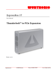
1
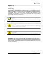
PCI Expansion System
User's Manual
64-bit/66MHz 7 Slot Series
PRELIMINARY
9918 Via Pasar
San Diego, CA 92126
Phone (858) 530-2511
Fax (858) 530-2733
www.magma.com
[email protected]
[email protected]
Copyright © 2003 MAGMA
This publication is protected by Federal Copyright Law, with all rights
reserved. No part of this publication may be copied, photocopied,
reproduced, stored in a retrieval system, translated, transmitted or
transcribed, in any form or by any means manual, electric, electronic,
electro-magnetic, mechanical, optical or otherwise, in whole or in part
without prior written consent from MAGMA.
Limitation of Liability
Information presented by MAGMA in this manual is believed to be
accurate and reliable. However, MAGMA assumes no responsibility for
its use. No license is granted by implication or otherwise to any rights of
MAGMA.
Product specifications and prices are subject to change without notice.
Trademark References
Trademarks and registered trademarks are proprietary to their
respective manufacturers.
M A G M A
Table of Contents
PREFACE
I
Advisories
Safety Instructions
i
ii
When Working Inside a Computer
Protecting Against Electrostatic Discharge
CHAPTER 1
ii
iii
INTRODUCTION
1
The 64-bit/66MHz 7 Slot PCI Expansion System
General Specifications
Rack-mount Specifications
Tower Specifications
Pre-Installation Information
Parts List
Tools Required for Installation
1
1
1
1
2
2
3
CHAPTER 2
4
INSTALLATION GUIDE
Step One: Install 64-Bit Host Interface
Step Two: Attach PCI Expansion and Power Cable(s)
PCI Expansion Cable Connection Diagram
4
5
5
Step Three: Recheck Installation
Step Four: Power Up
Step Five: Install Software Driver/Verify Installation
6
6
7
Windows XP Driver Install/Verification
Windows 2000 Driver Install/Verification
Windows ME Automatic Installation/Verification
Mac OS Automatic Installation/Verification
8
11
16
21
Step Six: Power Down and Remove Cover
23
Rack-mount Enclosure
Tower Enclosure
23
23
Step Seven: Install PCI Cards
Step Eight: Power Up Again
Step Nine: Install PCI Card Software
23
24
25
Windows Users:
Macintosh Users:
25
25
Step Ten: System Should Be Up and Running
Finishing Touches
26
26
CHAPTER 3
27
BUS HIERARCHY
Table of Contents
i
M A G M A
Bus Hierarchy
CHAPTER 4
27
WARRANTY & TECH SUPPORT
28
Product Warranty
30 Day Money Back Guarantee
Free Technical Assistance
Warranty & Repair in Seven Days
Returns for Repair/Replacement/Credit
Out of Warranty Repair
Advanced Replacement Service
Contacting Technical Support
Frequently Asked Questions
Returning Merchandise to MAGMA
28
28
28
28
28
29
29
30
30
31
APPENDIX A
32
COMPLIANCE
FCC Class A Notice
CE Certification
Safety Standards
Declaration of Conformity
ii
Table of Contents
32
32
32
33
M A G M A
Preface
Advisories
Three types of advisories are used throughout this manual to provide
helpful information or to alert you to the potential for hardware damage
or personal injury. They are Notes, Cautions, and Warnings. The
following is an example of each type of advisory. Use caution when
servicing any electrical component.
NOTE
An amplifying or explanatory comment related to procedural steps or
text.
CAUTION
Used to indicate and prevent the following procedure or step from
causing damage to the equipment.
WARNING
Used to indicate and prevent the following step from causing injury.
Disclaimer: We have tried to identify all situations that may pose a
warning or caution condition in this manual. However, MAGMA does not
claim to have covered all situations that might require the use of a
Caution or Warning.
Preface
i
M A G M A
Safety Instructions
WARNING
The Tower PCI Expansion System is to be installed on desktop or
tabletops only. The unit will become unstable if operated as a floor
standing unit and unintentional force is applied to the top of the unit.
Before handling the MAGMA PCI Expansion System, read the following
instructions and safety guidelines to prevent damage to the product and
to ensure your own personal safety. Refer to the “Advisories” section
for advisory conventions used in this manual, including the distinction
between Warnings, Cautions, and Notes.
♦
Always use caution when handling/operating the computer.
Only qualified, experienced, authorized electronics personnel
should access the interior of the computer. The power supplies
produce high voltages and energy hazards, which can cause
bodily harm.
♦
Use extreme caution when installing or removing components.
Unplug the power cord before removing the cover. The cover
can only be opened by persons having appropriate technical
training and experience necessary to be aware of hazards to
which they are exposed in performing a task and of measures
to minimize the danger to themselves or other persons. Refer
to the installation instructions in this manual for precautions
and procedures.
WARNING
High voltages are present inside the expansion system when the unit’s
power cord is plugged into an electrical outlet. Disconnect the power
cord from its source before removing the enclosure cover. Turning off
the power switch does not remove power to components.
Never modify or remove the radio frequency interference shielding from
your workstation or expansion unit. To do so may cause your installation
to produce emissions that could interfere with other electronic
equipment in the area of your system.
When Working Inside a Computer
Before taking covers off a computer, perform the following steps:
1.
ii
Turn off the computer and any peripherals
Preface
M A G M A
2.
Disconnect the computer and peripherals from their power
sources to prevent electric shock or system board damage.
3.
Follow the guidelines provided in “Regulatory Compliance
Statements” on the following page.
4.
Disconnect any telephone or telecommunications lines from
the computer.
In addition, take note of these safety guidelines when appropriate:
♦
To help avoid possible damage to systems boards, wait five
seconds after turning off the computer before removing a
component, removing a system board, or disconnecting a
peripheral device from the computer.
♦
When you disconnect a cable, pull on its connector or on its
strain-relief loop, not on the cable itself. Some cables have a
connector with locking tabs. If you are disconnecting this type
of cable, press in on the locking tabs before disconnecting the
cable. As you pull connectors apart, keep them evenly aligned
to avoid bending any connector pins. Also, before connecting a
cable, make sure both connectors are correctly oriented and
aligned.
CAUTION
Do not attempt to service the system yourself except as explained in
this manual. Follow installation instructions closely.
Protecting Against Electrostatic Discharge
Electrostatic Discharge (ESD) Warning
Electrostatic Discharge (ESD) is the enemy of semiconductor
devices. You should always take precautions to eliminate any
electrostatic charge from your body and clothing before touching
any semiconductor device or card by using an electrostatic wrist
strap and/or rubber mat.
Static electricity can harm system boards. Perform service at an ESD
workstation and follow proper ESD procedure to reduce the risk of
damage to components. MAGMA strongly encourages you to follow
Preface
iii
M A G M A
proper ESD procedure, which can include wrist straps and smocks,
when servicing equipment.
You can also take the following steps to prevent damage from
electrostatic discharge (ESD):
iv
♦
When unpacking a static-sensitive component from its shipping
carton, do not remove the component’s anti-static packaging
material until you are ready to install the component in a
computer. Just before unwrapping the anti-static packaging,
be sure you are at an ESD workstation or grounded.
♦
When transporting a sensitive component, first place it in an
anti-static container or packaging.
♦
Handle all sensitive components at an ESD workstation.
possible, use anti-static floor pads and workbench pads.
♦
Handle components and boards with care. Don’t touch the
components or contacts on a board. Hold a board by its edges
or by it’s metal mounting bracket.
Preface
If
M A G M A
Chapter 1
Introduction
The 64-bit/66MHz 7 Slot PCI Expansion System
MAGMA's 64-bit/66MHz 7 Slot PCI Expansion System is a generalpurpose bus expansion system for the Peripheral Component
Interconnect (PCI) local bus. The PCI expansion system consists of a
64/66 host interface card, a set of four 3–meter expansion bus cables (a
shielded, high-speed cable), an expansion daughter card, an expansion
motherboard and a rack-mount or tower enclosure with a power supply.
General Specifications
S
S
S
S
S
S
S
Backplane:
Standard Cable Length:
PCI Local Bus Specification:
PCI Bridge Architecture Spec:
Interconnect Bandwidth:
MTBF:
Operating Environment:
S
Supported Operating Systems
S
Warranty:
Seven 64-bit/66MHz PCI slots
3 meter
Revision 2.2
Revision 1.1
5 Gbps full duplex
60,000 hours
0º to 50º C Operating Temperature
-20º to 60º C Storage Temperature
5% to 85% Relative Humidity, Noncondensing
Windows XP/2000/NT/ME/98SE
MacOS X, Mac OS 9
1 Year Return to Factory
Rack-mount Specifications
S
S
S
S
S
Enclosure:
Dimensions:
Weight:
Cooling:
Available Options:
S
Power Supply:
4U rack-mount (All Steel)
19" W x 7" H x 17.7" D
24 lb or 11.804 kg
(1) 70-105 CFM fan (removable/cleanable air filter)
Disk Drive Bays for up to eight 3.5" internal disk drives
18 inch Rack-mount Slide Kit
400W (auto-switching) or
Hot-swappable 300W redundant (auto-switching)
Tower Specifications
S
S
S
S
S
S
Enclosure:
Dimensions:
Weight:
Cooling:
Disk Drive Bays:
Power Supply:
ATX Mid-Tower (Steel Chassis/Plastic Front)
7"W x 18.1"H x 17.3"D
22 lbs. or 10kg.
(1) 35 CFM high volume fan
(3) 5.25" external, (1) 3.5" external & (3) 3.5" internal
400W (auto-switching)
Chapter 1
Introduction
1
M A G M A
Pre-Installation Information
Before using the 7 Slot 64-bit/66MHz PCI Expansion System you should
perform the following steps:
•
Inventory the shipping carton contents for all of the required parts
•
Gather all of the necessary tools required for installation
•
Read this manual
Follow these suggested guidelines and cautions while setting up your
PCI Expansion System:
•
Only use the power cable(s) provided by MAGMA
•
Only use the interface cables provided by MAGMA
•
Use keyed connectors (to prevent attaching a cable backwards)
•
Be careful when routing signal cables to your devices
•
Avoid sharp bends or folds in the signal cable
•
Provide enough slack to allow easy device placement
•
Beware of sources of scuffing and abrasion damage to the cables
•
Secure the devices in their shelves using the appropriate hardware
•
Use the screws or brackets supplied with the device (suitable
mounting brackets, adapters, and hardware are available from your
local computer dealer or retailer)
Parts List
Qty
Item
1
1
1
1
1
1
7 Slot Rack-mount or Tower PCI expansion enclosure
Set of four 3-meter shielded CAT-5 patch cables (Grey, Blue, Red &
Green)
64/66 PCI host interface card
Power supply cord (2 supplied with 300W redundant PSU)
Software CDROM
User’s Manual
2
Chapter 1
Introduction
M A G M A
NOTE
The PCI Expansion System is shipped with many parts packaged in
a separate box within the larger box that the expansion system is
shipped in.
Tools Required for Installation
In order to complete the installation of the PCI expansion system you
will need the following tools:
•
•
A suitable Electrostatic Discharge Protective environment
One Phillips-head screwdriver
Chapter 1
Introduction
3
M A G M A
Chapter 2
Installation Guide
The following steps will guide you in completing the installation of your
new 64-bit/66MHz 7 Slot PCI Expansion System.
Electrostatic Discharge (ESD) Warning
All PCI cards are susceptible to electrostatic discharge. When
moving PCI cards, it is best to carry the cards in anti-static
packaging. If you need to set a PCI card down, be sure to place it
inside or on top of an anti-static surface. For more information, see
“Protecting Against Electrostatic Discharge”.
WARNING
High voltages are present inside the expansion system when the unit’s
power cord is plugged into an electrical outlet. Disconnect the power
cord from its source before removing the enclosure cover. Turning the
system power off at the power on/off switch does not remove power to
components. High voltage is still present.
CAUTION
Before touching anything inside the enclosure, move to an ESD station
and follow proper ESD procedure. Failure to do so may result in
electrostatic discharge damaging the computer or its components. For
more information, see “Protecting Against Electrostatic Discharge”.
Step One: Install 64-Bit Host Interface
Power down your host computer system.
Use the procedures for shutting down your system provided in your
owner's manual or system documentation. Turn off power to your
computer.
Remove the cover.
Install the 64-Bit Host Interface in any available PCI slot in your host
computer and secure with a retaining screw.
The 64-bit/66MHz PCI Host Interface Card is a standard "short"
universal PCI adapter card. Install it in your host computer by inserting
4
Chapter 2
Installation Guide
M A G M A
the card into any available PCI slot and securing it with a retaining
screw.
Step Two: Attach PCI Expansion and Power Cable(s)
A set of four 3-meter shielded, high-speed cables are included with your
PCI Expansion System. One end of each cable should be connected to
the RJ45 connectors on the 64-bit Host Interface and the other end
should be connected to the correct RJ45 connector on the rear of the
expansion system by following the diagrams shown below:
PCI Expansion Cable Connection Diagram
PCI Host Interface
Expansion System
L0
L0
Rx0
Rx0
Tx0
Tx0
L1
L1
Rx0
Rx0
Tx0
Tx0
CAUTION
All cables attached to the expansion system must be securely
fastened. If not fastened tightly, the connectors may cause intermittent
or lost connections.
Check that the expansion system On/Off switch is set to the OFF
position.
Connect the power cord to the power-in receptacle located at the rear of
the enclosure. If your expansion system includes a 300W redundant
power supply, make sure you attach a power cord to each power supply
module and set the power supply switch to the ON position.
Chapter 2
Installation Guide
5
M A G M A
NOTE
If at all possible, plug all power cords from the PCI Expansion System
and your host computer into a shared power strip, preferably one that
has surge and noise suppression circuitry built into it.
Step Three: Recheck Installation
Check your installation before powering up the PCI Expansion System
for the first time. Although the power supply has an over voltage
protection device built into it, it may not "trip" in time to fully protect a
device that has been improperly connected or whose power cable has
been damaged.
Step Four: Power Up
NOTE
The 400-watt and the 300-watt redundant power supplies are auto
switching, which means the power supply will automatically adjust to
the voltage required for the region you are in.
NOTE
For systems that have a 300W redundant power supplies; a red push
button is provided on the back of the enclosure to silence the audible
alarm in the event of a power supply failure.
You must apply power to the PCI Expansion System first and then
power up your host computer. This will allow the higher numbered PCI
buses in your hierarchy to be at a stable state at the time that the host
system issues its master power-on bus reset. In systems that perform
automatic PCI bus configuration, this will allow the configuration code to
recognize the PCI bus hierarchy and the attached devices.
If you have several PCI Expansion Systems in your configuration, you
should power up the most "downstream" expansion system first, then
each expansion system moving “upstream” and finally the host system
last.
There is an On/Off switch on the front panel as well as an LED indicator
to indicate power status. Verify that the green power indicator is ON.
6
Chapter 2
Installation Guide
M A G M A
There may also be an On/Off switch on the power supply, located in the
back of the expansion system. Make sure the power supply switch is in
the ‘On’ position before powering up.
When powering up, pay close attention to the eight LEDs on the 64-bit
Host Interface and the eight LEDs on the rear panel of the expansion
system. All LEDs must be solid green before the system will
function properly. If any LED is not solid green, power off the
system and check that the RJ45 connectors are seating properly
and connected to the correct port before powering up again.
WARNING
The expansion system will not work properly or may not be recognized
by the host computer unless all LEDs on the Host Interface and rear
panel are solid green.
Ensure that you have connected the cables properly by referring to the
diagram in Step Two.
Step Five: Install Software Driver/Verify Installation
NOTE
Only Microsoft Windows XP and Windows 2000 users need to install
the 64-bit/66MHz PCI Expansion Driver. All other operating systems
should automatically detect the PCI Expansion System and configure
properly.
Window XP users, go to page 8.
Windows 2000 users, go to page 11.
Windows ME users, go to page 16.
Mac OS users, go to page 21.
Chapter 2
Installation Guide
7
M A G M A
Windows XP Driver Install/Verification
The following dialog will appear the first time you boot your computer
with the PCI Expansion System installed:
Insert the CDROM that was included with your expansion system into
the CDROM drive of your computer.
Choose Install the software automatically (Recommended), then
click Next.
The following dialog should appear:
Click Finish.
The following dialog will appear:
8
Chapter 2
Installation Guide
M A G M A
Choose Install the software automatically (Recommended), then
click Next.
Your computer should automatically find the appropriate driver
and display the following dialog:
The following dialog should appear:
Click Finish.
Now you should see a yellow call-out box appear in the lower
right hand corner of your screen that reads, "Your new
hardware is installed and ready to be used."
You can verify that the expansion system is installed correctly by
checking that there are no exclamation mark (bangs) in the
Chapter 2
Installation Guide
9
M A G M A
Device Manager under the PCI Bus that the expansion system is
installed on.
á
Æ
Æ
Æ
Æ
Æ
Æ
Go to: Start
Control Panel
System (use Classic View)
Hardware
Device Manager
Choose ‘View devices by
connection’
locate the PCI Bus that the expansion system is
connected to. Your Device Manager should look similar to the
following:
PCI device installation is now complete. Continue to Step Six, page 23.
10
Chapter 2
Installation Guide
M A G M A
Windows 2000 Driver Install/Verification
The following dialog will appear the first time you boot your computer
with the PCI Expansion System installed:
Click Next.
The following dialog will appear:
Choose Search for a suitable driver for my device
(recommended), then click Next.
The following dialog will appear:
Chapter 2
Installation Guide
11
M A G M A
Insert the CDROM that was included with your expansion system into
the CDROM drive of your computer.
Make sure CD-ROM drives is checked, then click Next.
Your computer should automatically find the appropriate driver
and display the following dialog:
Click Next.
The following dialog will appear:
12
Chapter 2
Installation Guide
M A G M A
Click Finish, but you're not finished installing the expansion
system yet. You have only installed half of the expansion system
bridge devices. You can verify this by going to the Device
Manager to see the bridges that you have just installed:
á
Æ
Æ
Æ
Æ
Æ
Æ
Æ
Go to:
Start
Settings
Control Panel
System
Hardware
Device Manager
Choose ‘View devices by
connection
locate the PCI Bus that the expansion system is
connected to. Your Device Manager should look similar to the
following:
Chapter 2
Installation Guide
13
M A G M A
Although you were not prompted to do so, you must restart your
computer in order for your computer to see the PCI slots in the
expansion system.
á
Æ
Æ
Go to: Start
Shut Down
down menu
click OK.
Æ Choose ‘Restart’ from the drop
After restarting, your computer should automatically find the next
PCI bridge device. It may not be obvious to you that your
computer found any new hardware, but you can verify that the
expansion system is installed correctly by checking that there are
no exclamation mark (bangs) in the Device Manager under the
PCI Bus that the expansion system is installed on.
Your device manager should now look similar to the following:
14
Chapter 2
Installation Guide
M A G M A
PCI device installation is now complete. Continue to Step Six, page 23.
Chapter 2
Installation Guide
15
M A G M A
Windows ME Automatic Installation/Verification
The required software for the 64-bit/66MHz PCI Expansion System is
included with the Windows ME operating system. However, you should
follow the installation instructions below carefully.
The following dialog will appear the first time you boot your computer
with the PCI Expansion System installed:
Choose Automatic search for a better driver (Recommended), then
click Next.
The following dialog will appear:
Click Finish.
The following dialog will appear again:
16
Chapter 2
Installation Guide
M A G M A
Choose Automatic search for a better driver (Recommended), then
click Next.
The following dialog will appear again:
Click Finish.
The following dialog will appear:
Chapter 2
Installation Guide
17
M A G M A
Choose Automatic search for a better driver (Recommended), then
click Next.
The following dialog will appear, but don’t worry this is normal.
Click Finish.
Even though Windows ME was unable to locate the software for
the last device installed. Everything should still work properly.
To verify installation, go to Device Manager.
á
Æ Settings Æ Control Panel Æ
Æ View devices by type
Start
Manager
System
Æ
Device
Under Other devices, there should be two PCI Bridges. There
will be a ‘Question Mark’ in front of both PCI Bridges. This is
18
Chapter 2
Installation Guide
M A G M A
normal.
Your device manager should now look similar to the following:
Now go down to System devices, you should see two PCI
standard PCI-to-PCI bridges. These devices should not have
‘Question Marks’ or ‘Exclamation Marks’ in front of them.
Your device manager should now look similar to the following:
Chapter 2
Installation Guide
19
M A G M A
PCI device installation is now complete. Continue to Step Six, page 23.
20
Chapter 2
Installation Guide
M A G M A
Mac OS Automatic Installation/Verification
Mac OS X
When using Mac OS X no additional software or drivers are needed.
The operating system should automatically recognize the PCI
Expansion System.
To verify installation, go to Apple System Profiler.
Apple Menu
Æ About This Mac Æ More Info Æ Devices
You should see a pci-bridge device listed under PCI as shown below:
Any PCI Cards that you install in the expansion system will appear
behind the pci-bridge device.
Continue to Step Six, page 23.
Mac OS 9
When using Mac OS 9 no additional software or drivers are needed.
The operating system should automatically recognize the PCI
Expansion System.
Continue to Step Six, page 23.
To verify installation under Mac OS 9, you need to use a
software utility called MagmaSlots.
MagmaSlots is a simple utility application for displaying information on
PCI cards installed in the Macintosh computer. It uses the Mac OS
NameRegistry to discover what slots have PCI cards in them, and then
displays basic information for each card in a simple console window.
MagmaSlots can be downloaded our web site at:
www.magma.com/support/support.htm.
Chapter 2
Installation Guide
21
M A G M A
Launch the MagmaSlots application by double-clicking its icon. It is
recommended that you launch MagmaSlots from a location on your
desktop.
A console window similar to the one shown below should appear:
If you see this entry, it means that your computer has
recognized the MAGMA expansion system.
22
Chapter 2
Installation Guide
M A G M A
Step Six: Power Down and Remove Cover
It is recommended that you first shut down the host computer correctly
and then power down the expansion system to avoid ‘computer lock-up’.
Rack-mount Enclosure
Four screws retain the cover on the Rack-mount enclosure. They are
located on the rear of the unit along top edge of the top cover. Slide
cover back about 1 inch to disengage and remove straight up.
Tower Enclosure
Two screws retain the cover on the Tower enclosure. They are located
on the rear of the unit, one on the top and one on the bottom of the
cover's back edge. Slide the cover out from the back of the unit.
Step Seven: Install PCI Cards
Generally, when installing PCI cards in the expansion system, it should
make no difference what slot order you place your cards in, unless
specified by the PCI card manufacturer.
Slot ordering in the 7 Slot 64-bit/66MHz expansion system should begin
with the slot farthest away from the installed daughter card – labeled
SLOT 4.
Install PCI cards following PCI card manufacturer’s recommendations.
CAUTION
Prior to installing the MAGMA PCI Expansion System, you should be
familiar with the installation procedures for the PCI cards that you are
installing in the expansion system. Some PCI card manufacturers
recommend that you install their software driver(s) prior to installing the
hardware. If this is the case, you should install their driver before you
connect and power up the expansion system.
NOTE
It is good practice to install one PCI device at a time, especially when
configuring a large system. This can save you time later if you
experience a problem while installing several new devices. If you install
all PCI devices at one time, then experience a problem, it can be
difficult to determine which device is causing the problem.
Make sure that all PCI cards are fully seated in their connectors. When
correctly seated in its connector, you will notice a firm resistance when
Chapter 2
Installation Guide
23
M A G M A
you pull up gently on the card. To keep the cards in place, secure them
in the enclosure with their retaining screws (supplied with the PCI
Expansion System).
Take care when routing cables within the PCI expansion system in
order to avoid damaging the signal cables (especially unshielded flat
ribbon cables) or the power cables for internally installed devices. Be
sure to leave enough "slack" in the cables to allow you to easily remove
them if necessary to service the device(s).
NOTE
The sheer number of PCI cards and device drivers available makes it
impossible for MAGMA to fully test and certify all available PCI cards
for use in the PCI expansion system. Our best advice to you in this
regard is to insist on full PCI Specification compliance from your card
and system vendors. Cards and systems should be at least PCI
Specification Revision 2.0 compliant or better. Compliance in your
system motherboard, PCI cards and console firmware (or BIOS) is
your best assurance that everything will install and operate smoothly.
Not all PCI cards are as "well-behaved" as they should be. Sometimes
simply moving a PCI card that is having a problem to a different slot, or
reordering your cards in their slots, will alleviate "behavior" problems.
Step Eight: Power Up Again
You must apply power to the PCI Expansion System first and then
power up your host computer.
Remember, when powering up, pay close attention to the eight LEDs on
the 64-bit Host Interface and the eight LEDs on the rear panel of the
expansion system. All LEDs must be solid green before the system
will function properly. If any LED is not solid green or flickering,
power off the system and check that the RJ45 connectors are
seating properly and tightly before powering up again.
WARNING
The expansion system will not work properly or may not be recognized
by the host computer unless all LEDs on the Host Interface and rear
panel are solid green.
24
Chapter 2
Installation Guide
M A G M A
Step Nine: Install PCI Card Software
NOTE
Prior to installing the MAGMA PCI Expansion System, you should be
familiar with the installation procedures for the PCI cards that you are
installing in the expansion system. Some PCI card manufacturers
recommend that you install their software driver(s) prior to installing the
hardware. If this is the case, you should install their driver before you
connect and power up the expansion chassis. You may be required to
reboot before connecting the expansion chassis.
Your computer should now recognize any PCI devices you have
installed in the expansion system and prompt you to load drivers and/or
software if you have not done so already. Install PCI device software
following the manufacturers recommendations.
WARNING
You will most likely be prompted to Shut Down and Reboot your
system several times during PCI device installation. Please be patient,
each Shut Down and Reboot does serve a purpose and is required for
correct installation. If you Shut Down and Reboot when requested, it
may save you from having to make a call for Technical Support.
You can verify that your computer has recognized any PCI devices
installed in the expansion system by doing the following:
Windows Users:
Go to the Device Manager and choose ‘View by Connection’. You
should be able to see all devices installed in the expansion system by
locating the PCI standard PCI-to-PCI bridge and clicking the + signs to
display the chain of all PCI devices that your computer has found
installed in the expansion system.
Macintosh Users:
Mac OS X: Go to the Apple System Profiler and look under Devices.
You should be able to see all devices installed in the expansion system
by locating the pci-bridge and clicking the arrow to display the chain of
all PCI devices that your computer has found installed in the expansion
system.
Chapter 2
Installation Guide
25
M A G M A
Mac OS 9: You need to use a utility provided by MAGMA called
MagmaSlots. MagmaSlots is available for download at
www.magma.com/support/support.htm.
Step Ten: System Should Be Up and Running
Your system should now be up and running.
If you are having trouble with the system, turn off the host computer and
the expansion system, then check that all cards are seated in the slot
properly and all cables are connected securely.
If you are still having problems, contact MAGMA Technical Support for
more help.
Finishing Touches
After your system is working properly, replace any empty slots with slot
covers, and replace the host computer cover and the expansion system
cover.
26
Chapter 2
Installation Guide
M A G M A
Chapter 3
Bus Hierarchy
Bus Hierarchy
The following figure is representative of the PCI Bus hierarchy for the
64-bit/66MHz 7 Slot PCI Expansion System. This figure pictorially
conveys the overall PCI bus topology of the system.
The key point in the following figure of the 7 Slot Topology is the
connecting cables between the Host Interface and the Expansion
Backplane is actually a PCI bus itself.
In general, we do not know what the actual Bus numbers are. We only
know how they increment starting from the MAGMA Host Interface.
7 Slot Topology
NOTE
All PCI cards installed in the PCI Expansion System will appear on the
Third PCI Bus behind the PCI Bus that the Host Interface is installed
on.
Chapter 3
Bus Hierarchy
27
M A G M A
Chapter 4
Warranty & Tech Support
Product Warranty
MAGMA PCI Expansion Systems carry a one-year warranty against
defects in materials or workmanship from the date of shipment to the
original purchaser. Any products found to be defective in material or
workmanship will be repaired or replaced promptly.
Please Note: Products that have been modified will not be covered under this
warranty.
30 Day Money Back Guarantee
Any single standard MAGMA manufactured product may be returned
within 30 days of purchase for a full refund of the price paid for the
product being returned (must be in new condition in the original
packaging). If you are not satisfied, or chose the wrong product by
mistake, you do not have to keep it. Please call our Sales Group for a
Return Merchandise Authorization number before returning the product.
Free Technical Assistance
MAGMA is dedicated to providing competent, responsive technical
support both before and after the sale. We have staffed our support
department with professional software and hardware engineers and
given them the finest tools. MAGMA provides unlimited support to all
customers for the life of all products purchased.
Warranty & Repair in Seven Days
Any MAGMA manufactured product returned for repair under warranty
will be repaired and shipped within one week unless it is necessary for a
Technical Support Engineer to contact you and discuss the repair.
Repaired products are returned by the same shipping method as they
are received. Please call for a Return Merchandise Authorization
number before returning the product.
Please Note: All returns to MAGMA for Repair/Replacement/Credit must be
shipped back to MAGMA with all Shipping Charges and Duties Paid. Shipments
that arrive with freight or duties due, or returned collect, will be refused and sent
back to the sender at their own expense.
Returns for Repair/Replacement/Credit
It is not required, though highly recommended, that you keep the
packaging from the original shipment of your MAGMA Product.
However, if you return a product to MAGMA for warranty
repair/replacement or take advantage of the 30 day money back
28
Chapter 4
Warranty & Tech Support
M A G M A
guarantee, you will need to package the product in a manner similar to
the manner in which it was received from our plant. MAGMA cannot be
responsible for any physical damage to the product or component
pieces of the product (such as the host or expansion interfaces for PCI
expansion systems) that are damaged due to inadequate packing.
Physical damage sustained in such a situation will be repaired at the
owner's expense in accordance with Out of Warranty Procedures.
Please, protect your investment, a bit more padding in a good box will
go a long way to insuring the device is returned to us in the same
condition you shipped it in. Please call for a Return Merchandise
Authorization number before returning the product.
Out of Warranty Repair
Any out of warranty MAGMA manufactured product can be repaired at
the cost of MAGMA parts, plus current labor rate (not to exceed 50% off
the current list price for the same or equivalent product) plus freight.
Please call for a Return Merchandise Authorization number before
returning the product. There will be a minimum charge for 1 hour's labor
for evaluation of the product/unit. If repairs are needed, this will be
applied to the repair of the product. Once evaluation has been
completed, a Customer Support Representative will contact you with
any options you may have and to authorize the repair work before the
repair is performed.
Advanced Replacement Service
This Fee Based Service is primarily geared towards correcting severe
problems encountered in a system within the first 90 days after
shipment from the factory, but it is also available, on a graduated fee
scale during the term of the Warranty Period. Under the terms of this
Service, MAGMA will replace a warranted MAGMA manufactured
product prior to receiving the defective product from the customer.
Advanced replacements are available upon credit approval or by
providing a VISA, MasterCard or American Express card number as
security for the returned product. The cost for this service is the
appropriate,
graduated
fee
for
Advanced
non-refundable,
Replacement, as detailed in the chart below, plus freight.
PRODUCT
PCI Expansion System
PCI Expansion Boards
300/400W Power Supply
Other Power Supply
Any Product under $50.00
0-90 days
$150.00
$50.00
$50.00
$25.00
$25.00
TIME OWNED
91 days - 6 mos.
$300.00
$100.00
$100.00
$50.00
$25.00
6 mos. – 1 yr
$450.00
$150.00
$150.00
$75.00
$25.00
Please Note: This fee schedule subject to change. For current information
consult your Technical Support Engineer at the time of the request.
Chapter 4
Warranty & Tech Support
29
M A G M A
The item must be returned to MAGMA with all parts and components that were
shipped with it, in undamaged condition. The Customer shall be responsible for
missing components and/or systems or components that are returned and are
found to be physically damaged.
Non-Returned Advanced Replacements: Advanced Replacements
that are not returned within 30 days of replacement shipment will
automatically be charged to the securing credit card. If the product is
returned after the credit card is charged, the entity (person or company)
will be responsible for a Restocking Fee. This fee will be 25% of the
listed price of the replaced unit, with a minimum Restocking Fee of
$25.00. Product will only be accepted for return and restocking if the
Advanced Replacement is less than 90 days from date of replacement
unit shipment.
Contacting Technical Support
For a quick response, send an email to [email protected] with a
detailed description of your problem, or visit our web site at:
www.magma.com/support/support.htm
Our support department can also be reached by fax at (858) 530-2733
or by phone at (858) 530-2511. Support is available Monday through
Friday, 8:00 AM to 5:00 PM PT. When contacting MAGMA Technical
Support, please be sure to include the following information:
1) Name
2) Company Name
3) Phone Number
4) Fax Number
5) Email Address
6) MAGMA Product Name
7) MAGMA Serial Number
8) Computer Make
9) Computer Model
10) Operating System and Version
11) Make/Model of PCI cards in expansion system
12) Description of the Problem
Frequently Asked Questions
You can visit the MAGMA Technical Support FAQ pages on the Internet
at:
www.magma.com/support/support.htm
30
Chapter 4
Warranty & Tech Support
M A G M A
Returning Merchandise to MAGMA
If factory service is required, a Service Representative will give you a
Return Merchandise Authorization (RMA) number. Put this number and
your return address on the shipping label when you return the item(s)
for service. MAGMA will return any product that is not accompanied
by an RMA number. Please note that MAGMA WILL NOT accept COD
packages, so be sure to return the product freight and duties-paid.
Ship the well-packaged product to the address below:
MAGMA
RMA # ________
9918 Via Pasar
San Diego, CA 92126
USA
It is not required, though highly recommended, that you keep the
packaging from the original shipment of your MAGMA product.
However, if you return a product to MAGMA for warranty repair/
replacement or take advantage of the 30-day money back guarantee,
you will need to package the product in a manner similar to the manner
in which it was received from our plant. MAGMA cannot be responsible
for any physical damage to the product or component pieces of the
product (such as the host or expansion interfaces for PCI expansion
systems) that are damaged due to inadequate packing. Physical
damage sustained in such a situation will be repaired at the owner’s
expense in accordance with Out of Warranty Procedures. Please,
protect your investment, a bit more padding in a good box will go a long
way to insuring the device is returned to use in the same condition you
shipped it in. Please call for an RMA number first.
Chapter 4
Warranty & Tech Support
31
M A G M A
APPENDIX A
Compliance
FCC Class A Notice
Note - This equipment has been tested and found to comply with the limits for a
Class A digital device, pursuant to Part 15 of the FCC Rules. These limits are
designed to provide reasonable protection against harmful interference when the
equipment is operated in a commercial environment. This equipment generates,
uses and can radiate radio frequency energy and, if not installed and used in
accordance with the instruction manual, may cause harmful interference in which
case the user will be required to correct the interference at his own expense.
This device complies with Part 15 of the FCC Rules.
Operation is subject to the following two conditions:
(1) this device may not cause harmful interference,
and (2) this device must accept any interference
received including interference that may cause
undesired operation.
Changes or modifications not expressly approved by the party
responsible for compliance could void the user’s authority to operate the
equipment.
NOTE
The assembler of a personal computer system may be required to test
the system and/or make necessary modifications if a system is found
to cause harmful interferences or to be noncompliant with the
appropriate standards for its intended use.
CE Certification
The product(s) described in this manual complies with all
applicable European Union (CE) directives. For computer
systems to remain CE complaint, only CE-complaint parts
may be used. Maintaining CE compliance also requires proper cable
and cabling techniques. MAGMA will not retest or recertify systems or
components that have been reconfigured by customers.
Safety Standards
The products(s) described in this manual has met
the safety requirement of Underwriters Laboratories
(UL) for the US and Canadian market based on
UL’s published Standards for Safety.
32
Appendix A
Compliance
M A G M A
Declaration of Conformity
Manufacturer’s Name:
Manufacturer’s Address:
MAGMA, Inc.
A Mobility Electronics, Inc., Company
9918 Via Pasar
San Diego, CA 92126
USA
Declares that the product:
Computer Peripheral Equipment
Type of Equipment:
Product Name:
MAGMA PCI Expansion System
Model Number:
P7T46S, P7R46S, P7RR6S
to which this declaration relates, meet the essential health and safety
requirements and is in conformity with the relevant EU Directives listed below:
EU EMC Directive 89/336/EEC
EU Low Voltage Directive 73/23/EEC
EN 55022:1998/A1:2000; CISPR 22:1997/A1:2000 Class A, Limits and
Methods of Measurement of Radio Disturbance Characteristics of
Information Technology Equipment
EN 61000-3-2:1995 Power Frequency Emission for AC Main Harmonics
(Not Applicable for units under 75 Watts)
EN 61000-3-3:1995 Voltage Fluctuations
(Not Applicable for units under 75 Watts)
EN 50024:1998 Immunity, ITE Requirements
-EN 61000-4-2 Electrostatic Discharge (ESD) Immunity
(Supersedes IEC 801-2)
-EN 61000-4-3 (Formerly ENV 50140) Radiated RF Field Immunity
(Supersedes IEC 801-3 & IEC 1000-4-3)
-EN 61000-4-4 EFT Immunity for AC and I/O Lines
(Supersedes IEC 801-4)
-EN 61000-4-5 Surge (Line-Ground & Line-Line) Immunity
-EN 61000-4-6
(Formerly ENV 50141) Conducted Radio Field
(Common Mode) Immunity
-EN 61000-4-8 Power Frequency Magnetic Field Immunity
-EN 61000-4-11 Voltage Dip/Surge Immunity
EN 60950:2000 Safety of Information Technology Equipment (ITE) for CE
certification
The technical documentation required to demonstrate the above products meet
the requirements of the EMC Directive and Low Voltage Directive has been
compiled by MAGMA and is available for inspection by the relevant enforcement
authorities.
signed
Stan Seitz
Vice President of Operations
Scottsdale, AZ
May 9, 2003
A signed original copy of this document is available from MAGMA.
Appendix A
Compliance
33
Manual P/N 09-09905-01-A