1
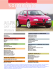
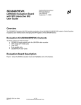
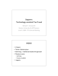
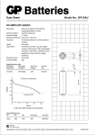
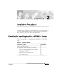
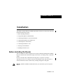
C H A PT E R
2
Installation
This chapter contains hardware installation procedures for the Cisco 1400 series router and
includes the following sections:
•
•
•
•
•
•
•
•
Before Installing the Router
Using POTS Splitters and Microfilters
Connecting the Router to Your Local Network
Connecting the Router to the ADSL Line
Connecting Power to the Router
Connecting the Router to a PC
Verifying Your Installation
Installing a Flash PC Card
Before Installing the Router
The Cisco 1400 series router is shipped to you ready for desktop mounting. Before making
the power and network connections, simply set the router on a desktop, shelf, or other flat
surface.
Be sure to read the safety information in the Regulatory Compliance and Safety
Information for the Cisco 1400 Series Routers document that came with your router. It
contains translated versions of all the safety warnings that appear in this guide.
Warning Read the installation instructions before you connect the system to its power
source.
Installation 2-1
Using POTS Splitters and Microfilters
Warning Only trained and qualified personnel should be allowed to install or replace this
equipment.
Warning Before working on a chassis or working near power supplies, unplug the power
cord on AC units; disconnect the power at the circuit breaker on DC units.
Warning Before working on equipment that is connected to power lines, remove jewelry
(including rings, necklaces, and watches). Metal objects will heat up when connected to
power and ground and can cause serious burns or weld the metal object to the terminals.
Warning Ultimate disposal of this product should be handled according to all national
laws and regulations.
Warning Before opening the chassis, disconnect the telephone-network cables to avoid
contact with telephone-network voltages.
Warning Do not work on the system or connect or disconnect cables during periods of
lightning activity.
Do not place anything on top of the router that weighs more than 10 pounds
(4.5 kg). Excessive weight on top of the router could damage the chassis.
Caution
Using POTS Splitters and Microfilters
Note This section applies only to the Cisco 1407 and Cisco 1417 routers.
POTS splitters and microfilters are used on telephone lines to ensure voice- and data-call
quality. This section describes splitters and microfilters and how and when to use them with
the Cisco 1407 and Cisco 1417 routers. POTS splitters result in the best data and voice
performance when the router and the telephone are used on the same telephone line, and
we recommend that you use a splitter.
2-2
Cisco 1400 Series Router Installation and Configuration Guide
POTS Splitters
POTS Splitters
A POTS splitter (also called a splitter) is installed on a telephone line that is connected to
both data (high-frequency) and voice (low-frequency) devices. The splitter routes the
high-frequency and low-frequency signals on the telephone line to the correct device.
Signals intended for the router can disrupt voice calls; signals intended for voice calls can
affect router operation.
Most splitters must be installed by the telephone company; however, some splitters can be
installed by the customer. If you are not sure what type of splitter to use, contact your
service provider.
Figure 2-1 is an example of a type of POTS splitter that is installed at the customer premises
by the customer. Other types of POTS splitters are installed by the telephone company on
an exterior wall of the customer premises.
Figure 2-1
POTS Splitter
To wall jack
To Cisco
1417
To phone
VOICE
22143
DATA
Installation 2-3
Using POTS Splitters and Microfilters
Microfilters
Microfilters are installed on telephones to improve voice-call quality when voice and data
equipment are using the same telephone line (twisted pair). You should use microfilters
with the Cisco 1407 and Cisco 1417 routers only when the two following conditions exist:
•
The documentation for the telephone(s) you are using with the router state that
microfilters should be used with the phone.
•
Poor telephone call quality is resolved by installing microfilter on the phone line.
Figure 2-2 shows one type of microfilter.
Figure 2-2
Microfilter
To wall jack
22142
WALL
PHONE
To phone
2-4
Cisco 1400 Series Router Installation and Configuration Guide
Common Splitter and Microfilter Configurations
Common Splitter and Microfilter Configurations
This section describes the most common scenarios using splitters and microfilters with the
Cisco 1407 and Cisco 1417 routers. The scenarios are listed from most common to least
common.
Telco-Installed Splitter
This scenario is described below and illustrated in Figure 2-2.
•
The splitter is installed by the telephone company on the customer premises. This type
of splitter is also referred to as a network interface device (NID).
•
•
•
The router and telephone are on separate lines (twisted pair) to the splitter.
The router and telephone share the same telephone line (twisted pair) to the telco.
Microfilters are optional and should be installed only if they improve telephone call
quality.
Telco-Installed Splitter
To telco
Splitter (NID)
Actual wall of building
22144
Optional
microfilters
Cisco 1407 or Cisco 1417
Installation 2-5
Using POTS Splitters and Microfilters
Customer-Installed Splitter
This scenario is described below and illustrated in Figure 2-3.
•
•
The splitter is installed by customer on the customer premises.
•
•
Router and telephone share the same telephone line (twisted pair) to the telco.
•
For telephones connected directly to the telephone line, microfilters are required.
Router and telephone are directly connected to the splitter, which is connected to the
telephone line.
For optional telephones connected through the splitter, microfilters are optional and
should be installed only if they improve telephone call quality.
Figure 2-3
Customer-Installed Splitter
To telco
Actual wall of building
Required microfilter
Splitter
Cisco 1407
or Cisco 1417
Optional telephones,
if supported by your telco
22145
Optional
microfilters
2-6
Cisco 1400 Series Router Installation and Configuration Guide
Common Splitter and Microfilter Configurations
Router and Telephone Using Separate Telephone Lines
This scenario is described below and illustrated in Figure 2-4.
•
•
Router and telephone are connected to separate telephone lines to the telco.
The microfilter is optional and should be installed only if it improves telephone call
quality.
Figure 2-4
No Splitter, Optional Microfilter
Line 1
to Telco (ADSL)
Line 2
to Telco (POTS)
Actual wall of building
22146
Optional microfilter
Cisco 1407 or Cisco 1417
Installation 2-7
Connecting the Router to Your Local Network
Connecting the Router to Your Local Network
Follow these steps, and refer to Figure 2-5 to connect the router to the local Ethernet
network through the yellow Ethernet port. You must provide a 10BaseT hub or switch to
connect the router to the local network.
Step 1
Connect one end of the yellow Ethernet cable to the yellow Ethernet port on the
router rear panel.
Step 2
Connect the other end of the cable to a network port on the hub or switch.
Note Figure 2-5 shows a Cisco 1401 router; however, this step is the same for all
Cisco 1400 series routers.
Figure 2-5
Connecting the Router to the Local Network
Cisco 1401
CONSOLE
LNK
OK
FLASH PC CARD
ATM 25
ETHERNET
Ethernet port
AUI
8
7
12412
1
Yellow
Ethernet cable
2-8
Ethernet hub or switch
Cisco 1400 Series Router Installation and Configuration Guide
Connecting the Router to the ADSL Line
Connecting the Router to the ADSL Line
This section describes how to connect the Cisco 1400 series router to the ADSL line.
Follow the steps for the router model that you are using.
Warning To avoid electric shock, do not connect safety extra-low voltage (SELV) circuits
to telephone-network voltage (TNV) circuits. LAN ports contain SELV circuits, and WAN
ports contain TNV circuits. Some LAN and WAN ports both use RJ-45 connectors. Use
caution when connecting cables.
Warning Hazardous network voltages are present in WAN ports regardless of whether
power to the router is OFF or ON. To avoid electric shock, use caution when working near
WAN ports. When detaching cables, detach the end away from the router first.
Cisco 1401 Router
Follow these steps, and refer to Figure 2-6 to connect the Cisco 1401 router to the ADSL
line:
Step 1
Connect one end of the green cable to the green ATM-25 port on the router.
Step 2
Connect the other end of the green cable to the appropriate port on the DSL
modem. On the Cisco 625 modem (shown in Figure 2-6), this is the port labeled
DATA.
Caution Always connect the green ATM cable to the green ATM port. Do not connect the
cable to the Ethernet port or to the console port. This will damage your router.
Installation 2-9
Connecting the Router to the ADSL Line
Step 3
Connect one end of the RJ-11 cable (that you supply) to the ADSL port on the
DSL modem. On the Cisco 625 modem, this is the port labeled LINE.
Step 4
Connect the other end of the RJ-11 cable to the ADSL wall jack.
Note Refer to the documentation that came with the DSL modem if you are not sure which
modem port connects to the router and which port connects to the ADSL line.
Figure 2-6
Connecting the Cisco 1401 Router to the ADSL Line
DSL modem
LINE
POWER
RESET
DATA
ADSL
(RJ-11)
wall jack
Cisco 1401
CONSOLE
LNK
OK
12414
RJ-11 cable
FLASH PC CARD
ATM 25
ETHERNET
Green RJ-45 cable
ATM-25 port
Cisco 1407 and Cisco 1417 Routers
Follow these steps, and refer to Figure 2-7 to connect the Cisco 1407 and Cisco 1417
routers to the ADSL line:
Step 1
Connect one end of the purple cable to the purple ADSL port on the router.
Step 2
Connect the other end of the purple cable to the ADSL wall jack.
Note If you are connecting the router to a POTS splitter that uses data port pins 3 and 4
for data, you should use the purple cable with the blue stripe. If you are not sure about what
type of POTS splitter to use, contact your ADSL service provider or your Cisco reseller.
2-10
Cisco 1400 Series Router Installation and Configuration Guide
Cisco 1407 and Cisco 1417 Routers
Caution Always connect the purple ADSL cable to the purple ADSL port. Do not connect
the cable to the Ethernet port or to the console port. This will damage your router.
Step 3
Either install a POTS splitter, or confirm with your service provider that a
Telco-installed POTS splitter has been installed. Refer to the “Using POTS
Splitters and Microfilters” section earlier in this chapter for details on when to
use a splitter.
Step 4
Install microfilters, if needed. Refer to the “Using POTS Splitters and
Microfilters” earlier in this chapter for details on when to use microfilters.
Figure 2-7
Connecting the Cisco 1407 and Cisco 1417 Routers to the ADSL Line
Cisco 1417
CONSOLE
ADSL
LNK
OK
FLASH PC CARD
17504
ADSL
(RJ-11)
wall jack
ETHERNET
Purple RJ-11 cable
ADSL port
Installation 2-11
Connecting the Router to a PC
Connecting the Router to a PC
If you want to configure the router using Cisco IOS software, you must connect the console
port to a terminal or PC. The cable and adapters required for this connection are included
with the router.
Follow these steps, and refer to Figure 2-8 to connect the router to a terminal, terminal
server, or PC:
Step 1
Connect the blue console cable to the blue CONSOLE port on the router.
Step 2
Use the correct adapter to connect the other end of the cable to the terminal or
PC.
Note If your terminal or PC has a console port that does not fit one of the adapters included
with the router, you must provide the correct adapter for that port.
Note Figure 2-8 shows a Cisco 1401 router; however, this step is the same for all
Cisco 1400 series routers.
Connecting the Console Cable to the Router
Cisco 1401
12418
Figure 2-8
CONSOLE
LNK
OK
FLASH PC CARD
ATM 25
ETHERNET
Blue
console cable
To PC or terminal
2-12
Cisco 1400 Series Router Installation and Configuration Guide
Connecting Power to the Router
Connecting Power to the Router
After you turn the router on, you can verify that you correctly installed the router by
checking that certain LEDs are lit.
Note Figure 2-9 shows a Cisco 1401 router; however, this step is the same for all
Cisco 1400 series routers.
Warning This equipment is intended to be grounded. Ensure that the host is connected to
earth ground during normal use.
Warning The power supply is designed to work with TN power systems.
Warning This product relies on the building’s installation for short-circuit (overcurrent)
protection. Ensure that a fuse or circuit breaker no larger than 120VAC, 15AU.S. (240VAC,
16A international) is used on the phase conductors (all current-carrying conductors).
Installation 2-13
Connecting Power to the Router
Follow these steps, and refer to Figure 2-9 to connect the router to power and turn it on:
Step 1
Connect one end of the power-supply cord to the power socket on the rear panel.
Step 2
Connect the other end of the power-supply cord to a power outlet.
Step 3
Turn on the router by pressing the power switch to the on ( | ) position.
Step 4
Confirm that the router has power by checking that the PWR LED on the front
panel is on.
Step 5
If you are using a DSL modem connected to a Cisco 1401 router, turn on the
modem. Refer to the documentation that came with the DSL modem if you are
not sure how to turn it on.
Connecting Power
Cisco 1401
CONSOLE
LNK
OK
FLASH PC CARD
ATM 25
ETHERNET
Power switch
2-14
Cisco 1400 Series Router Installation and Configuration Guide
12416
Figure 2-9
Verifying Your Installation
Verifying Your Installation
You can verify that you have correctly installed the router by checking the following LEDs:
Table 2-1
Using LEDs to Verify Installation
LED (Location)
What to Look for
PWR (front)
On steady when power is being supplied to the router.
OK (front)
• One blink per second when the router is in ROM monitor
mode.
• Several blinks per second when the router is running the boot
image in ROM monitor.
• On steady when the Cisco IOS software is loaded and
functional.
ETHERNET ACT (front)
Blinking when there is network traffic on the local Ethernet
network.
LNK (rear)
On steady when the router is correctly connected to the local
Ethernet network through the Ethernet port.
WAN CARRIER
On steady when the router has synchronized with the equipment
connected to the ATM-25 port (Cisco 1401 router) or with the
ADSL equipment at the service provider’s central office
(Cisco 1407 router).
OK (rear)
On steady when the Flash PC card is correctly installed in the
router. If this LED is off, reinstall the card according the
following section, “Installing a Flash PC Card.”
Installing a Flash PC Card
The Flash PC card is a writable card used to download new software to the router.
Note Although the router is shipped from Cisco with the Flash PC card already installed,
you might have to install it if someone has removed the card for any reason. For example,
to configure your router, the system administrator might remove the card, add a
configuration file to it, then return it to you.
Installation 2-15
Installing a Flash PC Card
You can perform these steps while the router is operating. Follow these steps, and refer to
Figure 2-10 to install the Flash PC card:
Insert the connector end of the card in the router slot, aligning the card edges
along the card-slot guides, and push the Flash PC card into the slot until the card
is seated.
Step 1
When the card is completely seated in the connector, the blue button left of the
Flash PC card slot pops out. If the blue button does not pop out, the card is not
seated. Press the blue button, remove the card, and reinsert it.
Verify that the OK LED (to the left of the card slot) is lit steadily, which indicates
that the card is inserted and functioning correctly. If the LED is not on, reinstall
the card.
Step 2
If you cannot successfully install the card, contact your Cisco reseller.
Note Figure 2-5 shows a Cisco 1401 router; however, this step is the same for all
Cisco 1400 series routers.
Figure 2-10
Installing a Flash PC Card
Blue plastic
eject button
Flash PC card slot
Cisco 1401
CONSOLE
LNK
OK
FLASH PC CARD
ATM 25
ETHERNET
Flash PC card
2-16
Cisco 1400 Series Router Installation and Configuration Guide
12682
Flash
PC card
OK LED