1
BELL SYSTEM PRACTICES
AT& TCo Standard
SECTION 463-110-100
Issue 12, October 1979
AUXILIARY SIGNALS
IDENTIFICATION, INSTALLATION, OPERATION, MAINTENANCE,
AND CONNECTIONS
1.
GENERAL
This section provides information on the
KS-16301 type, KS-8000 series, KS-20614
and KS-22001 signals with associated apparatus.
1.01
This section is reissued to:
1.02
Rate KS-8229 Manufacture Discontinued (MD).
•
Add information on KS-22001.
•
•
•
All KS-16301L2, L6, and L20 series signaling
devices are not intended for use with 115-volts
ac power and will be provided by the manufacturer
with two warning tags, one on the signal unit
frame and one on the signal unit power cord near
the plug. The tags will specify:
1.08
Delete Table D and add information to Table
A.
Change Table E to D
Delete KS-823312 Transformer Relay Set.
(This information will be included in Section
463-120-100. )
Warning:
60Hz.
Do not use
on 115 volts
The KS-20614 relay switch is intended for
use by handicapped persons. The List 1 is
equipped with a power cord and switches 115 volts
60 Hz. The List 2 provides a contact closure for
switching a customer low voltage supply not requiring
Underwriter Approval.
1.09
Delete KS-16626 Power Relay Set. (This
information will be included in Section
463-120-100.)
Since this reissue is a general reviSIOn, arrows
ordinarily used to indicate changes have been
omitted.
1.03
All signals operate on 115-volts 60-Hz power
unless otherwise noted.
The operating
voltage is stamped on the unit.
1.07
•
•
Certain signals are equipped with a 0.5- or
0.45-J.<f capacitor in series with a relay which
operates on telephone ringing current. The relay
and capacitor constitute a high impedance ringing
bridge.
1.06
All KS-16301 codes of signals, relays, and
backboxes are physically interchangeable.
These signals may be obtained with or
without control relays for use in indoor and
outdoor locations. Signals which do not contain a
control relay require an externally mounted power
relay set. One relay may operate several signals.
1.04
Relays that operate on telephone ringing
current have a 2-position sensitivity adjustment.
1.10
2.
IDENTIFICATION
To produce loud or distinctive
signals from:
Purpose:
2.01
When tip party identification is required, it
should be obtained through the ringer
associated with each telephone set. Refer to the
particular telephone set used for connections.
1.05
•
Vibrating bells
•
Single-stroke bells
•
Chimes
•
Horns
NOTICE
Not for use or disclosure outside the
Bell System except under written agreement
Printed in U.S.A.
BSP 463·110·100·i12_1979·10·01.jpg
Scanned by Frank Harrell, (Cowboy Frank) Castle Rock, Colorado Oct 09, 2012 16:12:12
Page 1
SECTION 463-110-100
•
Lamps.
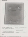
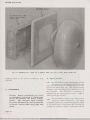
(a) A typical signal (Fig. 1) includes a backbox,
a signal premounted to a grilled cover, and
a control relay.
Ordering Guide:
2.02
•
•
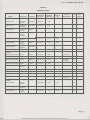
Refer to Table A for auxiliary signals
Refer to Table B for associated apparatus
which must be ordered separately.
3.
INSTALLATION
A.
Planning
Typical Installation Assembly:
3.04
(b) The armature on relays associated with
auxiliary signals restores to normal (open
contacts) by gravity. Always mount signal on a
vertical surface. A control relay, if used, must
be in the horizontal position.
Type of Installation:
The type of
installation determines the type of backbox
(see Table C). Backboards are not necessary.
3.05
Select a wall or column location for the
signaling device in accordance with the
following:
3.01
•
•
•
•
•
B.
Installing
Make sure power is disconnected before
w o rking o n circuit.
Under no
circumstances should the cord provided
for commercial power be passed through
a bole in a wall or be fastened
to a wall.
Not hazardous to maintenance personnel
avoid stairways, areas of heavy traffic, and
moving machinery
Best sound distribution
Safe from damage-remote from vehicular
traffic, excessive heat, and flammable or
corrosive fumes
Weatherproof Power Outlet KS-16301£18 (Fig. 8):
3.06
•
Accessible for maintenance or removal
•
Near power receptacle or conduit, where
required.
3.03
Wiring:
•
Not controlled by a switch
•
Separately fused, if possible
•
Within access of power cord.
Line Ringer:
Note: Any telephone station having auxiliary
signals (except a PBX station) must be equipped
with a ringer connected to the line at all
times to insure a ringing signal should
commercial power fail.
Used with KS-16301L19 backbox (ordered
separately).
Backbox, KS-16301
and 5):
3.07
Prior to
installation, a definite agreement must be
made with the customer to provide any necessary
power wiring (ac, de, receptacle, conduit) in
accordance with the following:
Customer-Provided
3.02
Provided to customer as required
•
•
•
•
•
•
•
Mount on a vertical surface
Use two slotted holes and one regular hole
for attaching backbox to surface
Use rustproof fasteners
Install backbox, List 9 or 11, so that the
customer may have the commercial power
connected (Fig. 2)
Terminate 3-conductor cord as shown in
Fig. 7
Do not fasten power cord to any surface
Do not pass power cord through wall holes
or partitions
Page 2
BSP 463-110-100-i12_1979-10-02.jpg
(Fig. 1, 2, 3, 4,
Scanned by Frank Harrell, (Cowboy Frank) Castle Rock, Colorado Oct 09, 2012 16:12:31
ISS 12, SECTION 463-110-100
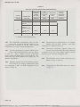
TABLE A
ORDERING GUIDE
SEE
OPERATING
CURRENT
OUTPUT
RELAY
FIG.
SEE
(AMPERES)
(dB)
OPERATIONt
NO.
TABLE
LOCATION
STROKE
VOLTAGE
Hazardous
Vibrating
115·volt ae
0.21
12
Vibrating
115-volt ae
0.21
12
Single
115-volt ae
0.12
12
Single
115·volt ae
0.12
12
Vibrating
115-volt ae
0.125
101.6
9
B
Single
115·volt ae
0.350
99.6
10
B
Vibrating
18-volt ae
0.325
101.6
11
B
Indoor
Vibrating
18-volt ae
0.325
101.6
13
KS-8229L13 (MD)
Indoor
Single
115-volt ae
0.07
48-volt de
14
KS·8229L14 (MD)
Indoor
Single
115-volt ae
0.07
48·volt ae
14
KS·8229L15 (MD)
Indoor
Single
115·volt ac
0.07
Ringing
14
SIGNAL
BELL
KS·8547L1
Indoor
KS-8547L2
Hazardous
Outdoor
KS·8547L3*
Hazardous
Indoor
KS·8547L4*
Hazardous
Indoor
Outdoor
KS·16301L3
Indoor
Outdoor
KS·16301L4
Indoor
Outdoor
KS-16301L20
Indoor
Outdoor
KS·20375L1
CHIME
Current
KS-8229L23 (MD)
Indoor
Single
115·volt ae
0.07
14
KS·16301L1
Outdoor
Single
115·volt ae
0.400
13
B
Indoor
KS·22001L2
Indoor
Single
115·volt ae
0.07
75.0
KS·22001L5
Indoor
Single
115-volt ac
0.07
75.0
48·volt de
KS·22001L6
Indoor
Single
115-volt ae
0.07•
75.0
48·volt ae
KS·22001L7
Indoor
Single
115-volt ac
0.07
75.0
Ringing
Current
HORN
KS·16301L2
Indoor
115-volt de
0.031
101.6
16
115-volt ae
0.450
106.6
17
1.30
101.6
18
Outdoor
KS-16301L5
Indoor
Outdoor
KS·16301L6
Indoor
48-volt ae
Outdoor
Page 3
BSP 463·110·100-i12_1979·10·03.jpg
Scanned by Frank Harrell, (Cowboy Frank) Castle Rock, Colorado Oct 09, 2012 16:12:53
SECTION 463-110-100
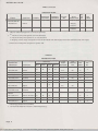
TABLE A (Contd)
ORDERING GUIDE
SEE
SIGNAL
LOCATION
STROKE
OPERATING
CURRENT
OUTPUT
RELAY
FIG.
SEE
VOLTAGE
(AMPERES)
(dB)
OPERATIONt
NO.
TABLE
SWITCH, RELAY
KS·20614Ll
Indoor
Ringing
7
Current
KS-20614L2
Indoor
8 :j:
Ringing
Current
*
t
May be ordered equipped for 115·volt de operation.
•
•
•
:j:
48-volt ac relays will operate on 9-volt minimum.
48·volt de relays will operate on 17-volt minimum.
Ringing current relays will operate on 53-volt minimum with wide airgap and 34-volt minimum with close airgap.
Does not include power receptacle or power cord.
TABLE B
ORDERING GUIDE
ASSOCIATED
USE WITH
v
APPARATUS
LOCATION
BACKBOX
KS-16301L8*
Indoor
KS·l6301L9*
Indoor
KS·l6301Lll*
Outdoor
KS-16301L19*
Outdoor
KS-22001L9
Indoor
BELL
•
•
•
•
HORN
CHIME
•
•
•
•
..
MOUNTING PLATE
KS·22001L8
•
•
•
•
•
•
Indoor
RELAY
•
•
•
•
POWER
FOR
CORD
CONDUIT
SEE
PROVIDED
INST
TABLE
NO
3
FIG.
Yes
No
c
No
Yes
c
2
No
Yes
c
4
Yes
No
c
5
No
Yes
c
No
No
OUTLET
KS-16301L18t
Outdoor
RELAY
KS·16301L15
Indoor-Outdoor
KS·16301Ll6
Indoor-Outdoor
KS·16301L17
Indoor
8
•
•
•
A
•
•
•
A
•
•
*
Mounting hardware not furnished.
t
Use with KS·16301L19 backbox (ordered separately).
•
Page 4
BSP 463·110·100·i12_1979·10·04.jpg
Scanned by Frank Harrell, (Cowboy Frank) Castle Rock, Colorado Oct 09, 2012 16:13:12
A
9
9
9
ISS 12, SECTION 463-110-100
BACK BOX
(LIST 19 OR LIST
8 OPTIONAL)
SOCKETS FOR
SIGNAL HINGE PINS
SIGNAL
PREMOUNTEO
TO GRILLED COVER
RAINHOOO
Fig. !-Exploded View of Assembled Signal Using Relay
TABLE C
BACKBOX
•
•
3.08
TYPE OF INSTALLATION
KS·16301L8
Indoor-Power Cord
KS-16301L9
Indoor-Conduit
KS·16301Lll
Outdoor-Conduit
KS·16301L19
Outdoor-Power Cord
KS·22001L9
Indoor-Conduit
An entrance hole for the telephone wires is
located in the bottom of each backbox
(Fig. 3)
Be sure that the gasket on the backbox is
in place (Fig. 7).
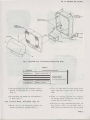
Control Relay, KS-16301 (Fig. 9):
•
Mount relay in the horizontal position on
mounts provided in backbox (Fig. 1).
For Use With or
Without Relay
(per job requirements)
•
•
•
Use a full cable pair for each signal circuit
when signaling circuits are in the same
cable.
When no talking circuits are involved,
low-voltage signal circuits may use half of
a cable pair or inside wire.
The List 15 units, manufactured after the
2nd quarter 1979, are provided with a
623P4 jack and connected to the wall jack
Page S
SECTION 463-110-100
RAIN HOOD
FUR NISHED
WITH LIST II
AND LIST 19
BACK BOX
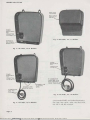
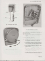
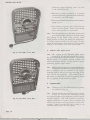
Fig. 4-KS-16301, List 11 Backbox
Fig. 2-KS-16301, List 9 Backbox
POWER
RE CEPTACLE
FOR
CONNECTION
TO RELAY
Fig. 5-KS-16301, list 19 Backbox
Fig. 3-KS-16301, List 8 Backbox
via a standard D4BU cord (ordered separately).
For long loop areas, move the lead from
the LO to the HI terminal.
Page 6
BSP 463·110-100-i12 1979-10-0G.jQg
Scanned by Frank Harrell, (Cowbo
Frank) Castle Rock, Colorado Oct 09, 2012 16:13:53
ISS 12, SECTION 463-110-100
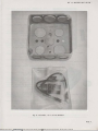
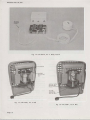
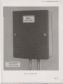
Fig. 6-KS-22001, list 9 4-lnch Backbox
Page 7
BSP 463·110·100·i12 1979-10-0l.jQg
Scanned by Frank Harrell, (Cowbo
Frank) Castle Rock, Colorado Oct 09, 2012 16:14:18
SECTION 463-110-100
Rainhood,
(Fig. 4):
3.10
•
•
•
•
•
•
Fig. 7-Power Cord Termination
•
•
•
Fig. 8-KS-16301, List 18 Outlet
•
Signals, KS-16301 (Fig. 13, 14, 15,
19, 20, 21, and 22):
3.09
•
•
Engage the two pins on front cover to form
a hinge with the two sockets which emerge
from backbox (Fig. 1)
Fasten the signal to the backbox with four
machine screws which are furnished (Fig. 1).
Switch
(Fig. 11
Mount relay to a vertical surface with
contacts at the bottom and within 12 inches
of local power receptacle.
Units manufactured after the 2nd quarter
1977 are provided with a 623P4 jack and
connected to the wall jack via a standard
D4BU cord (ordered separately). For long
loop areas, move the lead from the 10 to
the HI terminal.
Set single-pole double-throw switch on nearby
table or stand.
Connect visual indicator to receptacle in relay
housing.
Switch
(Fig. 12
Mount relay to a vertical surface with
contacts at the bottom.
Units manufactured after the 2nd quarter
1977 are provided with a 623P4 jack and
connected to the wall jack via a standard
D4BU cord (ordered separately). For long
loop areas, move the lead from the 10 to
the HI terminal.
Terminate 2-conductor cord on a 42A
connecting block, or equivalent, as a junction
point for the customer's low voltage circuit.
Set single-pole double-throw switch on nearby
table or stand.
Signals KS-8229 (MD) (Fig. 18):
3.13
•
Has slotted mounting holes for easy removal
from backboard
Page 8
BSP 463-110-100-112 1979-10-0B.·R
L19
Attach with furnished screws to the signal
unit (Fig. 1).
KS-20614L2 Relay
and 32):
3.12
and
For protection against the weather and insects
KS-20614L1 Relay
and 31):
3.11
�����BLY
KS-16301Lll
Scanned b Frank Harrell, (Cowbo Frank) Castle Rock, Colorado Oct 09, 2012 16:14:43
ISS 12, SECTION 463-110-100
NOTE:
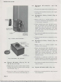
PROVIDED ON USOC RJ II C
JACK ( 623 P4), LIST 15 ONLY.
Fig. 9-KS-16301, Typical List 15, List 16, List 17 Relay
•
•
Has 3-conductor cord for terminating on a
42-type connecting block or equivalent
The signals are for indoor locations.
Signals, KS-8547 (Fig. 16):
3.14
•
The signals are for indoor and hazardous
locations
•
Signal is already attached to a backboard.
Caution: When the KS-8547 bell is
used in an explosive atmosphere,
extreme caution should be taken to
assure the installation conforms to
the requirements specified in Section
502-415-100.
Page 9
SECTION 463- 110- 100
Fig. 10-KS-22001, List 8 Portable Mounting Plate
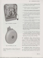
3.15
Signals, KS-20375L1 (Fig. 17):
(a) The KS-20375Ll bell mounts directly on a
4-inch square outlet box.
for use with the bell.
ordered separately.
Signals, KS-22001 (Fig. 23):
3.16
•
(b) The KS-20375L2 adapter is used when
mounting to a 2-inch octagonal outlet box
or a single or double gang plaster ring. The
KS-20375L3 (olive-gray) outlet box is also available
•
Mount on a vertical surface.
Use four slotted holes for attaching chime
to surface.
Page 10
BSP 463-110-100-i12 1979-10-lO.·R
These items must be
Scanned b Frank Harrell, (Cowbo Frank) Castle Rock, Colorado Oct 09, 2012 16:15:33
ISS 12, SECTION 463-110-100
RELAY COVER
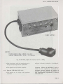
/ SWITCH UNIT
/ COVER
\
POWER
RECEPTACLE
"
POWER CORD
Fig. 11-KS-20614, List 1 Relay Switch
•
•
•
•
The KS-22001L2, L5, L6, and L7 replace
KS-8229L23, L13, L14, and L15, respectively.
The KS-22001Ll, L3, and L4 replace
KS-5594L5, L9, and LlO, respectively.
4.
The KS-22001L5, L6, and L7 are equipped
with-
(a) One plug ended 3-conductor power cord
4-feet long for connection to the power
circuit.
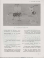
OPERATION
Noncontinuous Signals (Fig. 29): The
687B subscriber set has a cold cathode tube
and relay in place of the ringer. When the relay
is operated by rectified ringing voltage, the relay
contacts may be used to control a signal energized
from a local low voltage source.
4.01
4.02
(b) One 2-conductor cord 9-inches long with
spade terminals at one end.
•
•
The KS-22001L9 (Fig. 6) is a standard 4-inch
outlet box. It is provided with a screw-type
terminal block, jumper leads, and screws
for making connections to the chime signal.
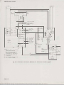
Continuous Signals (Fig.
30):
The
circuit operates as follows:
The KS-22001L7 is equipped with a 623P4
jack (USOC RJ11-C).
(a) Ringing current applied to line operates the
R relay through its secondary winding and
the top contacts 1 and 2 of SR relay to ground.
The KS-22001L8 (Fig. 10) is a portable
mounting plate used for applications where
mounting the chime directly is not desirable.
(b) The R relay locks operated by battery
through its primary winding, its own top
contacts 1 and 2, bottom contacts 3 and 2 of SR
Page 11
BSP 463-110-100-i12_1979-10-ll.jpg
Scanned by Frank Harrell, (Cowboy Frank) Castle Rock, Colorado Oct 09, 2012 16:15:55
SECTION 463-110-100
TO LOW
VOLTAGE
SIGNAL
Fig. 12-KS-20614, List 2 Relay Switch
Fig. 13-KS-16301, List 3 Bell
Fig. 14-KS-16301, List 4 Bell
Page 12
ISS 12, SECTION 463-110-100
(c) The R relay operated completes circuit
through its own top contacts 3 and 4 to
operate auxiliary relay or signal.
(d) Bottom contacts 1 and 2 of R relay may be
used to operate a line lamp indicator.
(e) When call is answered, B relay operates by
central office or PBX battery through station.
(f) The SR relay operates by battery through
its winding, contacts of B relay (operated),
and bottom contacts 1 and 2 of TO relay to
ground (Z wiring).
(g) Operation of SR relay opens locking circuit
of R relay which releases.
(h) Circuits to auxiliary signal and line lamps
open when R relay releases.
(i)
Fig. 15-KS-16301, List 20 Bell
Unanswered calls are handled by a timeout
feature. When R relay operates, ground is
connected through bottom contacts 3 and 4,
112-ohm heater winding of TO relay (Z wiring),
and top contacts 3 and 2 of TO relay to battery.
After approximately 30 seconds, thermally operated
bottom contacts 1 and 2 of TO relay will open.
This opens locking circuit of R relay and circuit
restores to normal.
(j) If call is answered, SR relay operates as
previously described. Circuit is completed
from battery through TO relay, bottom contacts
1 and 2 of SR relay (operated), and bottom
contacts 1 and 2 of TO relay to ground. This
opens heater winding circuit of TO relay.
4.03
Fig. 16-KS-8547, List 1 Bell
4.04
relay, bottom contacts 1 and 2 of TO relay (Z
wiring) to ground, or to switch to ground (Y
wiring).
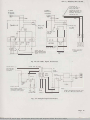
KS-20614Ll
Relay Switch (Fig. 31):
This relay is operated by station ringing
voltage to control a 2-conductor 115-volts 60-Hz
receptacle. The switch reverses function of the
relay contacts so that the 115-volts 60-Hz receptacle
can be either normally on or off with reversal
occurring during the ringing interval. Provides
for control of any alerting device (visual, tactile,
or audible) that operates on 115 volts 60 Hz and
draws 5 amperes or less noninductive load.
KS-20614L2 Relay Switch (Fig. 32):
Operation of the List 2 is similar except
the contacts are used to control a customer-provided
low voltage circuit (maximum 30 volts and 3.2
Page 13
BSP 463-110-100-112 1979-10-B.·R
Scanned b Frank Harrell, (Cowbo Frank) Castle Rock, Colorado Oct 09, 2012 16:16:37
SECTION 463-110-100
ADAPTER
I..IST2
PLATE
KS-20375,
I<S-2037!!, LIST 3 OR
LIST 4 (OLIVE GRAY)
OUTLET BOX
\
\
Fig. 17-KS-2037S, List 1 Bell, List 2 Adapter Plate, List 3 or 4 (Olive Gray) Outlet Box
amperes) wired to the 12-inch 2-conductor cord
provided.
A.
Signals, KS-16301
The KS-16301L3 (vibrating bell) has a volume
adjustment. On the Wheelock Signal Company
type, the adjustment is a hexagonal nut on the
rear of the signal (Fig. 13). The Sperti-Faraday
Company type adjustment is on the back of the
bell resonator.
The direction of adjustment is
stamped near the adjusting nut or screw. Table A
shows operating currents.
5.01
5.
MAINTENANCE
Danger: Before performing any work
on equipment connected to commercial
power, de-energize the power supply
circuit.
The customer shall arrange
for power disconnection and reconnection
on power circuits other than plug and
outlet.
The KS-16301L4 (single-stroke bell) uses a
cotter key volume adjustment. The signal
is shipped with the key inserted through the lowest
of the three holes in the sleeve that contains the
plunger for maximum volume. To decrease volume,
5.02
Page 14
BSP 463·110·100·i12_1979·10·14.jpg
Scanned by Frank Harrell, (Cowboy Frank) Castle Rock, Colorado Oct 09, 2012 16:16:55
ISS 12, SECTION 463-110-100
TELEPHONE
LINE
CONNECTIONS
POWER
CORD
Fig. 18-KS-8229 Chime (MD)
Fig. 20-KS-16301, List 2 Horn
move cotter key to intermediate or top hole in
the sleeve (Fig. 14).
Replace defective signals with complete list
number.
5.03
B.
Relays, KS-16301, KS-20614
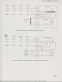
The Lists 15, 16, and 17 relays should meet
the following requirements: (Table D)
5.04
•
•
•
Fig. 19-KS-16301, List 1 Chime
•
The armature should not chatter when the
relay is operated with the specified voltage.
The armature should not bind or stick;
gauge by feel.
The armature airgap is adjusted on Wheelock
Signal Company relays by moving a lever
on the bottom of the relay.
In Sperti-Faraday Company relay, the
armature airgap is adjusted by rotating the
Page 15
BSP 463·110·100·112 1979·10·15.·R
Scanned b Frank Harrell, (Cowbo Frank) Castle Rock, Colorado Oct 09, 2012 16:17:18
SECTION 463-110-100
armature airgap adjusting screw 1/2 turn
to the desired setting.
•
•
•
Minimum contact pressure is 6 grams,
measured with relay operated either electrically
or manually; use 70H gauge.
Thecontactsshould make almost simultaneously;
gauge by eye.
The armature and pole piece should be free
of dirt or metal filings. Clean with 112-inch
relay cleaning strips or equivalent.
The KS-16301L15 and KS-20614 relays used
as a ringing bridge should not chatter during
dial pulsing to the extent that contacts make.
Check position of HI or LO sensitivity adjustment,
ie, HI for long loop or LO for dial area. If relay
meets all requirements but chatters on dial pulsing,
replace in accordance with local instructions.
5.05
C.
KS-8229 (MD) Signal Chime
Fig. 21-KS-16301, List 5 Horn
The volume of the KS-8229 (MD) signal
chime (Fig. 18) may be adjusted by a screw.
No other adjustment should be made. Should the
plunger stick in its guide, remove plunger and
clean with mineral spirits. If this does not correct
operation, replace signal device.
5.06
Some auxiliary signals can cause malfunctions
in frequency counters at computer installations
due to arcing of the ac contacts of the signal,
inducing noise in the ac line, and radiating in the
line cord of the computer. The problem can be
alleviated by installing a 0.02-�tf capacitor across
the ac contacts of the auxiliary signal.
5.07
6.
6.01
CONNECTIONS
Connections for KS-16301 signals and relays
are shown in Fig. 24.
Several signals may be connected as shown
in Fig. 25. This has the advantage of only
one ringing bridge on the telephone line for several
auxiliary signals. The total number of auxiliary
signals connected to a power relay set should not
exceed the current carrying capacity of the relay
contacts. Special commercial power wiring is not
needed between relay set and signals.
6.02
Fig. 22-KS-16301, List 6 Horn
Page 16
BSP 463·110·100·112 1979·10·16.·R
Scanned b Frank Harrell, (Cowbo Frank) Castle Rock, Colorado Oct 09, 2012 16:17:37
ISS 12, SECTION 463-110-100
NOTE:
LIST 7 COMES EQUIPPED
WITH A623 P4 JACK
LIST 2 IS DIRECTLY
WIRED TO 115V, 60HZ.
Fig. 23-KS-22001 Chime
Page 17
BSP 463-110-100-i12_1979-10-17.jpg
Scanned by Frank Harrell, (Cowboy Frank Castle Rock Colorado Oct 09
01
SECTION 463-110-100
TABLED
RELAYS, KS-16301 OPERATING REQUIREMENTS
RELAY
LIST NO.
15
OPERATING
DC
CURRENT
RESISTANCE
IMPEDANCE
CONTACT-
AT MAX.
OF RELAY
RELAY
OF RELAY
CARRYING
VOLTAGE
COIL
COIL
CAPACITY
VOLTAGE
AMPERES
OHMS
OHMS
0.011
4500
-
AMPERES
18- to 48-volts de
30- to 48-volts
0.025
1000
1920
0.012
4500
7550*
OPERATING
5
60-Hz ac
39- to 90-volts
20-Hz ac
(ringing voltage)
16
9- to 48-volts
0.404
26.3
60-Hz ac
17
•
12- to 78-volts de
0.069
118
-
1130
Includes 0.45-,uf series capacitor.
The KS-8233L2 transformer relay set has
been used to connect several signals to one
telephone line as shown in Fig. 26. This may be
encountered in some existing installations.
6.03
Connections for noncontinuous low voltage
signals such as bells, buzzers, and lamp
indicators are shown in Fig. 29.
6.06
Continuous operating signals, either low
voltage or power operated, should be connected
as shown in Fig. 30. Low voltage signals connect
directly to the 15D key telephone unit.
6.07
Typical connections for signals which do not
have a self-contained power relay are shown
in Fig. 27.
These signals require commercial
power wiring between relay set and signal. For
information on the KS-16626 Power Relay Set, see
Section 463-120-100.
6.04
Auxiliary signals may be installed on 4-party
full selective or 8-party semiselective lines
by connecting a 531C or 687B subscriber set as
shown in Fig. 28.
6.08
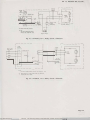
The KS-20614 relay switch connections are
shown in Fig. 31 and 32.
6.09
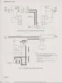
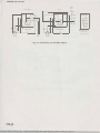
Connections for KS-22001 chimes are shown
in Fig. 33.
6.05
Page 18
'
BSP 463-110-100-i12_1979-10-18.jpg
Scanned by Frank Harrell, (Cowboy Frank) Castle Rock, Colorado
Oct 09, 2012 16:18:18
ISS 12, SECTION 463-110-100
TO POWER
RECEPTACLE
TO POWER
IN BACK BOX
IN BACKBOX
/
RECEPTACLE
TO OUTLET IN
LIST 15,16,0R 17
RELAY FOR DUAL,
POTENTIAL USE,OR TO
f
POII£R RECEPTACLE IN
BACKBOX
OR SINGLE
POTENTIAL USE
CORD
I
I �
S-16301,LI5
�LAY
OUTLET FOR
OUTLET FOR
KS-16301
KS-16301
SIGNAL*
SIGNAL*
KS-16301 ,LI6
AND LIT
RELAYS
60HZ
Ll6-9 TO 48V
Ll7-12 TO 78 VDC
t
*LIST 1,2,3,4,0R
TO
L1 NE
SIGNALING
TO TEL LINE
5
IN SULATED AND
STORED
Fig. 24-KS-16301 Signal Connections
TO
DRY CELLS,
PBX BATTERY,
OR
R ING ING
C U RRENT
[
INSIDE WIRE OR CABLE
Tt-
,-----
o.s UF
J
TO
OTHER
,.----o.s UF
SIGNALS
(SEE NOTE)
POWER
RELAY
SET
623P4
UNIT S
JACK ON
'-----./
MANUFACTURES
AfTER 2ND QUARTER 1979
(KS-16301, LIST 15 ONLY)
�
TO TEL L1 NE
CORD
TO
OTHER
SIGNALS
NOTE'
SIGNALS DESIGNATED FOR USE WITH
DC DO NOT CONTAIN A CAPACITOR.
Fig. 2S-Multiple Signal Connections
Page 19
BSP 463-110-100-i12_1979-10-19.jpg
Scanned by Frank Harrell, (Cowboy Frank) Castle Rock, Colorado Oct 09, 2012 16:18:46
- SECTION 463-110-100
CONN
COML
POWER
I
I
��·��
INSIDE WIRE
OR CABLE
-...._
CONN
'-------./
BLOCK
TO TEL L1 NE
Fig. 26-KS-8233, list 2 Transformer Relay Connections
0.45
Uf
(NOTE
I
2)
'""'' f�
I
:
SIGNAL
TOGGLE S\1 :H
(NOTE
I
I
r� t
L
623P4 JACKS
I NOT£ 4 I
I)
0:
t
t
�
�
HG
"'
"'
\\ \
T
I
I
I
c
�
\
R
I. LIST 9 RELAY IS EQUIPPED \liTH A TOGGLE SWITCH
NOTES:
2. Ll ST II AND
WHICH \/ILL DISCONNECT RELAY rROM LINE.
3.
4.
12
RELAYS DO NOT CONTAIN A CAPACITOR
AND ARE NOT TO BE CONNECTED ACROSS
HA5 1, Mi:Ch\NICAL
TELEPHONE LINES.
LIST 10 RELAY
Ll
ON
1 97 9
STS B, 9,10 AND 1l UNITS MANUFACTURED AFTER
2ND QUARTER
INSULATED AND S TORED
TO TEL OR
SIGNALING LINE
Fig. 27 -KS-16626 Power Relay Set Connections
Page 20
BSP 463·110·100·i12_1979·10·20.jpg
LATCH WITH PUSH
BUITDN RELEASE.
Scanned by Frank Harrell, (Cowboy Frank) Castle Rock, Colorado Oct 09, 2012 16:19:16
ISS 12, SECTION 463-110-100
I OR 5
2 OR 6
3 OR 7
4 OR 8
______!_.
�
______I__
R
--
�
--2._
�
�
GRD
-
GRO
-
R
-
___!_.
PARTY
PARTY
PARTY
PARTY
(BK)
TO AUX SIGNAL
OR
RELAY SET
Fig. 28-Connections for Auxiliary Signals on Party Line
PARTY
IORS
I!RIDGED
RINGING
____!__..
2 OR 6
3 OR 7
4 OR 8
R
--
T
-
�
PARTY
PARTY
GRO
�
�
___!!____.
PARTY
GRD
___!__..
TO AUX
LOW VOLTAGE
SIGNALS
LOW VOLTAGE
AC OR DC
SUPPLY
[�
[
Fig. 29-Connections for Noncontinuous Low Voltage Auxiliary Signal
Page 21
BSP 463-110-100-i12_1979-10-2l.jpg
Scanned by Frank Harrell, (Cowboy Frank) Castle Rock, Colorado Oct 09, 2012 16:19:45
SECTION 463-110-100
TO STATION
TO lINE
R
r-----.
R
T
::,_.,"
SUPPLY
[
l---l
IJ
-· """"'
-1---<
�
1
8
;;]'; IRI
2 MF
7
9
"i' (T)
b� cD
tjj�
I
(R)
(T )
SA
400[
2
R
1.1
I
I
I
I
I
J
5
3BF
3
P-475n
B
10
2
I
12
4
G OR
G
L
G
B
J
J
y
{!)
@
7
II
6
1·--]
_I
TO:
12
TO LAMP
BAT. SUPPLY
WHEN USED
®
14
BATTCRY
CUTOFF
SWITCH
(!)
8
P
T
��·
23511
2
-L.I3 I
4
®
5T
SR
4B
I
l
3
2
B
3!
�I
THIS
I
CONTACT OPENS
ON HEATER
WINDING ONLY--
®
USE WHEN BATTERY CUTOFF KEY
IS PROVIDED.
USE TO PROVIDE AUTOMATIC TIME
OUT Of LOCKED IN SIGNAL.
Page 22
Scanned by Frank Harrell, (Cowboy Frank) Castle Rock, Colorado Oct 09, 2012 16:20:11
2
nTo
soon lJ 3Br
1?;
2
�
7
5TR
®
4BR
30A KEY
Hl UNIT
Fig. 30-Connections and Circuit Operation for Continuous Auxiliary Signals
BSP 463-110-100-i12 1979-10-22.jpg
9
10
zsn
I
TO LINE LAMP
INO ICATOR
WHEN USED
L.
IJ Jb
5
�
NOTES:
I. PROVIDE IBE KEY TEL UNIT WHEN
USEO WITH THE 555 PBX.
2. ISO KEY TEL UNIT CANNOT BE
USED WITH RING·THROUGH
REPEATING COIL. USE 14A KTU.
180 OR IBE
KEY TEL UNIT
(NOH I)
TO POWER
SUPPLY FOR
AUX SIG
B
III---II•
s-3200 n
I
r;+ I
13
TO AUX SIG HAVING
CONTROL RELAY
ASSOCIATED WITH
SIGNAL
6
2
I
150 KEY
TEL UNIT
(NOTE 2)
TO
AUX
SIG
II
4
IP
I
2 Mf
(
1'--4
J
..-
T
ISS 12, SECTION 463-110-100
623P4
I NOTE) I
JACK
IR)
IY)
) (BK)
(G)
*
�---- �
1-- --- - - - ---,
I
TERM.
BOARD
r;:ol
It *I
II HI *I
SENSITIVITY
9100.0.
0.47
UF
I
L_ �
0
L::::
I
I
I
I
RELAY
J
______ _
OUTLET FOR
VISUAL
I
L
____
I
_j
R OCKER SWITCH
INDICATOR
INSULATED AND STORED
NOTE'
1977
TO ll5V
ON UNITS MANUFACTURED
AFTER 1ST QUARTER,
60HZ
OUTLET
Fig. 31-KS-20614, List 1 Relay Switch-Schematic
,--
1
I
TERM.
BOARD
r--,
I LO
I
-- -
, --
-
--
-,
I
I
I
SENSITIVITY
91000
0.47
UF
OM
�
..C.::
C c, -i-- -----1 .:.;
L--r--11- I
I
I
I
L�-�---
RE A Y
L
__
I
I
I
I
J
L-----
I
I
TO LOW
VOLTAGE
POWER
SOURCE
_j
ROCKER S�ITCH
______
I
I
I
I
_j
NOTE'
ON UNITS MANUFACTURED AFTER 1ST QUARTER, 1977
* NEON LAMP �Ill NOT OPERATE ON lll< VOLTAGE
t
INSULATED AND STORED
Fig. 32-KS-20614, List 2 Relay Switch-Schematic
Page 23
BSP 463·110-100-i12 1979-10-23.jpg
:3�4-�
'
Scanned by Frank Harrell, (Cowboy Frank) Castle Rock, Colorado Oct 09, 2012 16:2 \)0"
-----
, SECTION 463-110-100
LISTS
5
AND
6
LIST
(W)
JACK
l
l)
�
�
(BK)
0
usoc
RJIIC
7
(623P4)
�
IRJ
(G)
1/
=
I
I
�
�
�
115
"'
VAC
=
�
48V
�
;
LO
115
-J,
�
�
=
115
VAC
Page 24
24 Pages
Scanned by Frank Harrell, (Cowboy Frank) Castle Rock, Colorado
3
24 VAC-LIST I
Fig. 33-Connections for KS-22001 Chimes
BSP 463·110-100-i12 1979-10-24.jpg
20-28 VOC·LIST
38-56 VDC·LIST 4
Oct 09, 2012 16:20:54
VAC-LIST 2