1
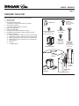
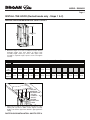
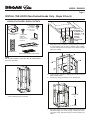
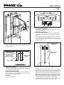
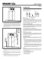
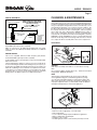
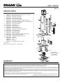
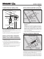
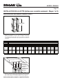
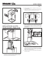
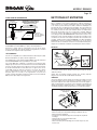
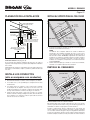
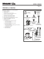
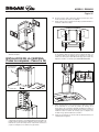
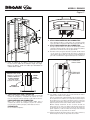
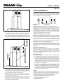
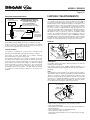
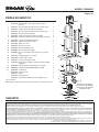
MODEL EI5936SS
Page 1
Chimney Island
Range Hood
READ AND SAVE THESE INSTRUCTIONS
FOR DOMESTIC COOKING ONLY
WARNING
WARNING
TO REDUCE THE RISK OF FIRE, ELECTRIC SHOCK, OR INJURY
TO PERSON(S) OBSERVE THE FOLLOWING:
1. Usethisunitonlyinthemannerintendedbythemanufacturer.If
you have questions, contact the manufacturer at the address or
telephonenumberlistedinthewarranty.
2. Beforeservicingorcleaningunit,switchpoweroffatservicepanel
andlockservicedisconnectingmeanstopreventpowerfrombeing
switch on accidentally. When the service disconnecting means
cannot be locked, securely fasten a prominent warning device,
suchasatag,totheservicepanel.
3. Installation work and electrical wiring must be done by qualified
personnelinaccordancewithallapplicablecodesandstandards,
includingfire-ratedconstructioncodesandstandards.
4. Sufficient air is needed for proper combustion and exhausting
of gases through the flue (chimney) of fuel burning equipment to
preventbackdrafting.Followtheheatingequipmentmanufacturer’s
guideline and safety standards such as those published by the
National Fire Protection Association (NFPA), and the American
SocietyforHeating,RefrigerationandAirConditioningEngineers
(ASHRAE),andthelocalcodeauthorities.
5. Thisproductmayhavesharpedges.Becarefultoavoidcutsand
abrasionsduringinstallationandcleaning.
6. Whencuttingordrillingintowallorceiling,donotdamageelectrical
wiringandotherhiddenutilities.
7. Ductedfansmustalwaysbeventedtotheoutdoors.
8. Useonlymetalductwork.
9. Donotusethisunitwithanyothersolid-statespeedcontroldevice.
10.Thisunitmustbegrounded.
2. NEVERPICKUPAFLAMINGPAN–Youmaybeburned.
3. DONOTUSEWATER,includingwetdishclothsortowels–aviolent
steamexplosionwillresult.
4. UseanextinguisherONLYif:
A. YouknowyouhaveaClassABCextinguisher,andyou
knowhowtooperateit.
B. Thefireissmallandcontainedintheareawhereitstarted.
C. Thefiredepartmentisbeingcalled.
D. Youcanfightthefirewithyourbacktoanexit.
*Basedon“KitchenFireSafetyTips”publishedbyNFPA
TO REDUCE THE RISK OF A RANGE TOP GREASE FIRE:
a) Never leave surface units unattended at high settings. Boilovers
cause smoking and greasy spillovers that may ignite. Heat oils
slowlyonlowormediumsettings.
b) AlwaysturnhoodONwhencookingathighheatorwhenflambéing
food (i.e. Crêpes Suzette, Cherries Jubilee, Peppercorn Beef
Flambé).
c) Cleanventilatingfansfrequently.Greaseshouldnotbeallowedto
accumulateonfanorfilters.
d) Useproperpansize.Alwaysusecookwareappropriateforthesize
ofthesurfaceelement.
TO REDUCE THE RISK OF INJURY TO PERSON(S) IN THE EVENT
OF A RANGE TOP GREASE FIRE, OBSERVE THE FOLLOWING*:
1. SMOTHERFLAMESwithaclose-fittinglid,cookiesheet,ormetal
tray,thenturnofftheburner.BECAREFULTOPREVENTBURNS.
IF THE FLAMES DO NOT GO OUT IMMEDIATELY, EVACUATE
ANDCALLTHEFIREDEPARTMENT.
CAUTION
1. Forindooruseonly.
2. Forgeneralventilatinguseonly.Donotusetoexhausthazardous
orexplosivematerialsandvapors.
3. To avoid motor bearing damage and noisy and/or unbalanced
impeller,keepdrywallspray,constructiondust,etc.offpowerunit.
4. Yourhoodmotorhasathermaloverloadwhichwillautomatically
shutoffthemotorifitbecomesoverheated.Themotorwillrestart
when it will cool down. If the motor continues to shut off and
restart,havethehoodserviced.
5. The bottom of the hood MUST NOT BE LESS than 24” and
recommended at a maximum of 36” above cooktop for best
captureofcookingimpurities.
6. Two installers are recommended because of the size of this
hood.
7. Toreduceriskoffireandtoproperlyexhaustair,besuretoduct
airoutside.Donotexhaustairintospaceswithinwallsorceilings
orintoattics,crawlspaces,orgarages.
8. Becarefulwheninstallingthedecorativeflueandhood,theymay
havesharpedges.
9. Thishoodisnotintendedtobeusedasashelf.
10.Pleasereadspecificationlabelonproductforfurtherinformation
andrequirements.
Register your product online at: www.broan.com
Installer: Leave this manual
with the homeowner.
Homeowner: Operation and Maintenance
instructions on pages 8 & 9.
MODEL EI5936SS
Page 2
PLAN THE INSTALLATION
INSTALL THE CEILING SUPPORT
ROOF CAP
8” MINIMUM
6” ROUND
DUCT
8½”
ON CENTER
FRONT
DECORATIVE
FLUES
HOOD
24” TO 36” ABOVE
COOKING SUFACE
6” ROUND
ELBOWS
HOOD
CENTERLINE
EAVE
VENT
DUCT
CENTERLINE
OFFSET 1” TO
REAR OF HOOD
DUCT CENTER LINE
(1” to rear of hood centerline)
HOOD
CENTER
LINE
The minimum hood distance above cooktop MUST NOT BE
LESSthan24”.
A maximum of 36” above cooktop is recommended for best
captureofcookingimpurities.
Distances over 36” are at the installer and users discretion;
providingthattheceilingheightpermits.
HOOD
CENTERLINE
1. Constructwoodframingthatisflushwithinteriorsurfaceof
theceilingjoists.
NOTE
Hood distance above cooktop is: Minimum 24”, Maximum
36”. 9-10 ft. ceilings may require Flue Extension Model
FXNE59SS, depending on installation height (purchase
separately). Discard the upper and lower flues, mounting
frame, and trim strips supplied with your hood and replace
themwithFlueExtensionModelFXNE59SS.
2. Finishopeningtomatchsurroundingceilingcarefullymarking
framinglocation.
INSTALL THE WIRING
HOUSE WIRING
IN THIS AREA
INSTALL THE DUCTWORK
(Ducted Hoods Only)
FRONT
5”
1. Decidewheretheductworkwillrunbetweenthehoodand
theoutside.
2. Astraight,shortductrunwillallowthehoodtoperformmost
efficiently.
3. Long duct runs, elbows and transitions will reduce the
performance of the hood. Use as few of them as possible.
Larger ducting may be required for best performance with
longerductruns.
4. Installwallcaporroofcap.Connectroundmetalductworkto
capandworkbacktowardsthehoodlocation.Useducttape
tosealthejointsbetweenductworksections.
3½”
HOOD
CENTERLINE
3½”
2”
HOOD
CENTERLINE
GROUNDINGINSTRUCTIONS
Thisappliancemustbegrounded.Intheeventofanelectrical
short circuit, grounding reduces the risk of electric shock by
providinganescapewirefortheelectriccurrent.
Positiontheelectrical(housewiring)withinthespacecoveredby
thedecorativeflueandwhereitwillnotinterferewiththeround
duct.Makesurethelengthofthehousewiringisaminimumof5
feet.Itmaybeshortenedafterhoodisinstalledatcorrectheight
andelectricalconnectionismade.
MODEL EI5936SS
Page 3
PREPARE THE HOOD
Unpackhoodandcheckcontents.Youshouldreceive:
1- HoodAssembly
1- GlassCanopy
1- DecorativeFlueAssembly
(consistingof2-upperand2-lowerfluesections)
1- HoodFrameAssembly
(consistingofupperandlowersections)
2- UpperFlueTrimStrips
2- LowerFlueTrimStrips
1- AluminumGreaseFilter(installedonhood)
4- 35WMR16GU10HalogenLamps(includedonhood)
1- PartsBagcontaining:
6- MountingScrews(4mmx38mmCrossRecessedPanHead)
3- MountingScrews(4mmx12mmCrossRecessedPanHead)
12- MountingScrews(3mmx5mmCrossRecessedPanHead)
4- MountingScrews(.188”x.250”CrossRecessedFlatHead)
1- SuctionCupTool
3- WireNuts
1- InstallationManual
3 MOUNTING
SCREWS
(4mm x 12mm
Cross Recessed
Pan Head)
3 WIRE NUTS
12 MOUNTING SCREWS
(3mm x 5mm Cross
Recessed Pan Head)
BULB SUCTION
CUP TOOL
4 MOUNTING
SCREWS
(.188” x .250”
Cross Recessed
Flat Head)
HOOD
FRAME ASSEMBLY
GLASS
CANOPY
6 MOUNTING
SCREWS
(4mm x 50mm
Cross Recessed
Pan Head)
FLUE
TRIM
STRIPS
DECORATIVE
FLUE
ASSEMBLY
HOOD
ASSEMBLY
DECORATIVE
FLUE
ASSEMBLY
MODEL EI5936SS
Page 4
INSTALL THE HOOD (Ducted hoods only - Steps 1 & 2)
NON-DUCTED HOOD INSTALLATION - SKIP TO STEP 3.
LENGTH
“L”
1. Determinelength“L”offrameassemblybasedupondesired
installation height. (See chart below.) To adjust frame
assembly height, remove (8) screws, slide upper frame
assembly to required height, replace screws and tighten
securely.
Desired Hood Distance (Above 36" High Cooktop)
24"
Ceiling
Height
8 Feet
9 Feet
25"
26"
27"
28"
29"
30"
31"
32"
33"
34"
35"
36"
* 23-5/8”
* 22-5/8”
* 21-5/8”
* 20-5/8”
35-5/8"
34-5/8"
33-5/8"
32-5/8"
Frame Length “L”
* 20-5/8"
19-5/8”
18-5/8”
17-5/8”
16-5/8”
15-5/8”
9 Feet
with
32-5/8"
FXNE59SS
31-5/8"
30-5/8"
29-5/8"
28-5/8"
27-5/8"
26-5/8"
10 Feet
with
44-5/8"
FXNE59SS
43-5/8"
42-5/8"
41-5/8"
40-5/8"
39-5/8"
38-5/8"
* Non-duct recirculation louvers will be exposed in ducted configuration
FRONT
CEILING
MATERIAL
IS INSTALLED.
CEILING
FRAMING
ABOVE SHOWN
AS DOTTED
LINES.
2. Alignframeassemblytoceilingframing,andattachtoceiling
framing with (6) 4mm x 50mm screws. Tighten securely,
makingsurethattheupperframebracketistightagainstthe
ceiling.
DUCTED HOOD INSTALLATION - SKIP TO STEP 9.
37-5/8"
36-5/8"
MODEL EI5936SS
Page 5
INSTALL THE HOOD (Non-Ducted Hoods Only - Steps 3 thru 8)
NON-DUCT KIT MODEL RKE59 CONTENTS
4 MOUNTING
SCREWS
(3mm x 10mm
Cross Recessed
Pan Head)
NON-DUCT PLENUM
ASSEMBLY
4 MOUNTING
SCREWS
(.188” x .375”
Cross Recessed
Flat Head)
FRONT
4 FOAM
RECTANGLES
FILTER TRAY
CEILING
MATERIAL
IS INSTALLED.
CEILING
FRAMING
ABOVE SHOWN
AS DOTTED
LINES.
4. Alignupperframeassemblytoceilingframing,andattach
to ceiling framing with (6) 4mm x 50mm screws. Tighten
securely,makingsurethattheupperframebracketistight
againsttheceiling.
FLEXIBLE DUCT
NON-DUCTED RECIRCULATION FILTERS
NT
FRO
NOTE
Non-ductedinstallationsrequireNon-DuctKit,ModelRKE59
(purchaseseparately).
5. Install non-duct plenum to upper frame bracket using (4)
3mmx10mmscrews.
6. Feedhousewiringaroundfrontofnon-ductplenum.
FRONT
LENGTH
“L”
3. Disassembletheframebyremoving(8)screws.Setaside
screwsandlowerframeassembly.
7.
Determinelength“L”offrameassemblybasedupondesired
installationheight.Seechartonpage4.Slidelowerframe
overupperframeandattachwith(8)screwspreviouslyset
aside.
MODEL EI5936SS
Page 6
10. Removetheprotectiveplasticfilmcoveringthedecorative
flueandthehoodatthistime.
T
ON
FR
8. Attachfoamsealstoplenumandframe,aroundtheplenum
openings.
INSTALL THE HOOD
(All Hoods - Steps 9 thru 25)
11. Removethegreasefilterbypullingdownthemetallatchtab
andtiltingfilterdownward.
12. Carefullyplaceglasscanopyontopofthehood.Alignnuts
onglasscanopywithholesinsidethehood.Attachcanopy
with(4).188”x.250”longflatheadscrews.Tightenscrews
securelybutDONOTOVERTIGHTEN.
ELECTRONICS
MOUNTING
BRACKET
13. Alignthekeyholeslotsonthebottomoftheframeassembly
withthe(4)mountingscrewsonthetopofthehood(partially
tightened).Slidethehoodsothescrewheadsareseated
entirely on mounting screws and that hood is level.Then
tightenscrewscompletely.
14. Install(1)4mmx12mmlongscrewintothelowerframeand
hoodtosecure.
9. Removetapeholdingelectronicsmountingbrackettohood.
Remove(3)screwsontopofhoodchassis andsetscrews
aside. Rotate electronics mounting bracket as shown and
securetohoodwithsame(3)screws.
MODEL EI5936SS
Page 7
FRONT
17. NON-DUCT HOOD ONLY
Attachfiltertraytobottomofhoodusing(4).188”x.375”
mountingscrews.
18. NON-DUCT HOOD ONLY
Snapin2-non-ductfiltersintofiltertraysbyengagingfilter
tabonside,rotatingupward,andpressingfirmlyon(2)filter
clips.
19. Reinstall grease filter by aligning rear filter tab with slots
in the hood. pull down the metal latch tab, push filter into
position and release. Make sure filter is securely engaged
afterinstallation.
15. Remove wiring cover and connect house wiring to hood
wiring–blacktoblack,whitetowhite,greentogreen.Reattachwiringcover.
6” ROUND STEEL DUCT
(Ducted Hood)
6” ROUND FLEXIBLE
METAL DUCT
(Non-Ducted Hood)
4mm x 12mm
SCREWS
3mm x 5mm
SCREWS
DECORATIVE
FLUE
DUCT LENGTH
16. FOR DUCTED HOOD
Measure, cut, and install steel duct between hood’s duct
connector and duct rough-in in ceiling. Use duct tape to
makealljointssecureandairtight.
FOR NON-DUCTED HOOD
CAUTION
Measure,cut,andinstallflexiblemetalductbetweenhood’s
duct connector and non-duct plenum. Use duct tape to
makealljointssecureandairtight.
Donotuseplasticduct.
20. Carefully place the (2) upper flue sections on the hood
frame.
Note that the louvers should be on top for a non-ducted
application,andonthebottomformostductedapplications.
Makesurethattheclearanceholes(larger)areinfrontofthe
attachmentholes(smaller)wherethetwofluehalvesmeet.
While gently pushing the two flue sections together and
slidingthemtothetopoftheframe,attachthefluesections
togetherthroughthetopattachmentslotsandintotheupper
framemountingholesusing(2)4mmx12mmscrews.
21. Gently push the lower parts of the flues together and
completeattachmentusing(6)3mmx5mmscrews.
MODEL EI5936SS
Page 8
OPERATION
Always turn the hood ON before cooking in order to establish an air
flowinthekitchen.Afterturningofftherange,letthehoodrunforafew
minutestocleartheair.
Operatethehoodasfollows:
DELAY
OFF LIGHT
OFF
FAN
22.Carefullyplacethe(2)lowerfluesectionsonthehoodframe,
andoverlappingtheoutsideoftheupperflueassembly,and
nestedintotheglasscutout.Makesurethattheclearance
holes(larger)areinfrontoftheattachmentholes(smaller)
where the two flue halves meet.While gently pushing the
twofluesectionstogether,attachthefluesectionsusing(6)
3mmx5mmscrews.
(A)
(A)
FANSPEED
LEDINDICATORS
OFF
TurnsthefanOFF
FAN (1-Pushbutton Switch, 3-Fan Speeds)
TurnsthefanONtothelastselectedspeed,andactivatesablueLED
indicatingthefanspeedsetting.PressingtheFANbuttonasecondtime
will index the fan speed and LED indicator to the next highest setting.
PressingtheFANbuttonwhenthefanisatthehighestspeedsettingwill
indexthefanandLEDindicatortothelowestsetting.
DELAY-OFF (10 Minute Delay-OFF)
Activatesthe10minutedelayofffeaturewhenthefanisON(anyspeed).
Whenactivated,theblueLEDindicatorabovetheselectedspeedsetting
willblink.ThehoodfanwillautomaticallyturnOFFafter10minuteshas
elapsed.TheDELAY-OFFbuttoncanbepressedatanytimeduringthe
10minutecountdowntoturnoffthefeature.
LIGHT (1-Pushbutton Switch, 3-Light Intensities)
TurnsthelightsONtothelowestintensity.PressingtheLIGHTbuttona
secondtimewillindexthelightintensitytothenexthighestlevel.Pressing
theLIGHTbuttonwhenthelightsareatthehighestintensitywillturnthe
lightsoff.
FILTER CHANGE INDICATION
After30hoursoffanoperation,thethreeblueLEDindicatorswillblink
simultaneously,indicatingthatitistimetocleanthegreasefilters.Toreset
thefiltercleantimer,pressandholdtheOFFbuttonfor3seconds.The
blinkingLEDindicatorswillturnoff.
HEAT SENTRY SYSTEM
ThisrangehoodisequippedwithastandardHeatSentrysystemthat
monitorsexcessivetemperatureandautomaticallyturnsthefanspeed
onHIGH.
1) IfthefanisON,theHeatSentrysystemwillincreasethefansettingto
it’shighestspeedwhenthetemperatureiselevated.Theblueindicator
for fan speed (3) will illuminate and blink at a high rate, indicating
thattheheatsentryfunctionisactivated.Oncethetemperaturehas
reduced,theHeatSentrysystemwillchangethefanspeedtothe
originalsetting.
2) IfthefanisOFF,theHeatSentrysystemwillautomaticallyturnthe
fanontoit’shighestspeedwhenthetemperatureisabovenormal.
Theblueindicatorforfanspeed(3)willilluminateandblinkatahigh
rate, indicating that the heat sentry function is activated.After the
temperaturehasloweredtonormal,thefanwillturnoff.
23. Snap lower flue trim strips (thin) into lower flue channels.
Engagetabsonstripsintoslotsinsidelowerfluechannels.
Pushtrimstripsdownsotopedgeisevenwithtopedgeof
lowerflue.
24. Measurethedistancefromtheceilingtothetopedgeofthe
lowerflueassembly(A).Cuttheupperfluetrimstrips(wide)
tothisdimension.
25. Snap upper flue trim strips into the flue channels in the
upperflueassembly.Ensurethatthetopofthetrimstripis
evenwiththetopedgeoftheupperflueassembly.
FUSES
The Range Hood Control Board contains a Main Fuse to protect the
controls from power surges. New fuses can be purchased at a local
electronicsupplystore.Use5A,120V,5mmdiameter,20mmlong,fastacting,cartridge-typefuses.
Toreplaceafuse(byqualifiedperson(s)):
1. Disconnectpoweratserviceentrance.
2. Removedecorativeflues.
3. Removecontrolcover
4. Removeandinspectfuse.
MODEL EI5936SS
Page 9
CLEANING & MAINTENANCE
MAKE-UP AIR DAMPER
MAKE-UP AIR DAMPER
MODEL EW56, EW58, EI59 SERIES
MAKE UP DAMPER CONNECTION
(switched low voltage)
20 GAUGE BELL WIRE FOR LOW
VOLTAGE CONNECTION ON
TOP OF HOOD
24V
TRANSFORMER
(INCLUDED)
HOOD
GRD
120 VAC
60 HZ
DRY CONTACT
TERMINAL
BUSHING
FOR LOW
VOLTAGE
CONNECTION
ThehoodiscompatiblewithBroanMake-UpAirDamperModelMD6Tor
ModelMD8T(optional).Purchaseseparately.
Make the connection to the Make-Up Air Damper with low voltage
wiring, as shown. See Make-UpAir Damper instructions for additional
information.
REMOTE CONTROL
The hood is compatible with Broan Radio Frequency (RF) Remote
ControlModelBCR1(optional).Purchaseseparately.
TolinktheBCR1remotecontrolwiththehood,pressandholdtheLIGHT
buttonfor3-seconds.
TheblueLEDindicatorswillturnonandoffinsuccessiontoindicatethe
hoodisinRFlinkingmode.Wheninthelinkingmode,pressanykeyon
theRFremote.Anaudiblebeepwillbeheardatthehood,andthehood
LED’swillstopblinkingifasuccessfullinkisaccomplished.Iftheremote
controldidnotsuccessfullylinkwiththehood,thelinkingmodewillbe
deactivated after 12 seconds, and the LED’s will stop the sequential
blinking.RefertotheBCR1instructionsforadditionalinformation.
Forperformance,appearance,andhealthreasons,cleanfilter,fanand
grease-ladensurfaces.Useonlyacleanclothandmilddetergentsolution
onstainlessandpaintedsurfaces.Cleanall-metalfiltersinthedishwasher
usinganon-phosphatedetergent.Discolorationofthefiltermayoccurif
usingphosphatedetergents,orasaresultoflocalwaterconditions-but
thiswillnotaffectfilterperformance.Thisdiscolorationisnotcoveredby
the warranty. Clean the non-duct recirculating filter surfaces frequently
with a damp cloth and a mild detergent. DO NOT immerse filters in
water or put in dishwasher. Change the non-duct recirculating filters
every6months.Forreplacementnon-ductrecirculatingfilters-purchase
S99010365orModelFILTERE56.Themotorispermanentlylubricated
andneverneedsoiling.Ifthemotorbearingsmakeexcessiveorunusual
noise,replacetheblowerassemblywithanexactservicereplacement.
LIGHT BULBS
SUCTIONCUPTOOL
(1)
PUSHIN
HALOGEN
BULB
(2)
ROTATE
CLOCKWISE
WARNING
Bulbsmaybehot.Alwaysallowbulbstocooldownbeforeremoving
them.
Use (2) Halogen Bulbs (included with hood) - 120V, 35 W, shielded
halogenbulbs-MR16withGU10base.
NOTE
SuctionCupTool(includedwithhood)canbeusedtoinstalland
removelightbulbs.Alignpinsonbulbwithlargediameteropening
onsocket,thenpushbulbintowardshoodandrotateclockwiseuntil
firmlyseated.Thepositionofthebulbsocket(depth)isadjustableand
mayrequireadjustmentwhen:a)certainbrandsofbulbsaredifficultto
install.b)thebulbprotrudestoofarbelowthelightpanel.
LAMPSOCKET
BRACKET
LIGHT
PANEL
SCREWS
Tochangethedepthofbulbsockets:
- Remove2screwsonlightpanel–setscrewsaside
- RemoveLightPanel.
- Loosen2ScrewsholdingLampSocketBrackettoLightPanel.
- Adjustsocket/brackettodesireddepth.
- Re-tightenscrewssecurely.
- Re-attachlightpanelwith2screwsthatwerepreviouslysetaside.
MODEL EI5936SS
Page 10
SERVICE PARTS
KEY PARTNO.
1 S99527476
2 S99527477
3 S99527479
4 S99527478
5 S99527443
6 S99527444
7 S99527445
8 S99527446
9 S99527447
10 S99527449
11 S99527450
12 S99527454
13 S99010366
14 S99010365
15 S99527459
16 S99527460
17 S99527461
18 S99527462
19 S99527465
20 S99526798
21 S99527468
* S99527470
* S99527471
* S99527474
* S99527481
3
DESCRIPTION
QTY.
DecorativeUpperandLowerFlues(2ofeach)
1
UpperFlueTrim(2pcs.)
2
HoodFrameAssembly
1
LowerFlueTrim(2pcs.)
2
Motor/BlowerAssembly
1
LightSocket(includesmountinghardware)
4
LightSocketBracket(includesmountinghardware) 4
UserInterfaceAssembly
1
UserInterfaceCable
1
ControlBoard
1
ControlEnclosure
1
LightPanel(pair)
2
AluminumGreaseFilter
1
Non-DuctRecirculationFilters(pair)
1
Non-DuctFilterTray
1
CurvedGlassPlate
1
DamperAssembly
1
6”Dia.ExpandableFlexibleAluminumDuct
1
Non-DuctPlenumAssembly
1
35WMR16GU10HalogenLamp
4
Capacitor
1
HeatSensor
1
Fuse
1
PartsBag
1
UserInterfaceButton(4-pack)
4
*Notshown.
OrderservicepartsbyPartNo.-notbyKeyNo.
2
1
19
4
18
17
16
11
21
9
8
10
7
6
12
20
Replacement
partscanbeordered
onourwebsite:
www.broan.com
5
15
14
WARRANTY
13
BROAN-NUTONE ONE YEAR LIMITED WARRANTY
Broan-NuTone warrants to the original consumer purchaser of its products that such products will be free from defects in materials or workmanship for a period of one year from the date of original purchase. THERE ARE NO
OTHER WARRANTIES, EXPRESS OR IMPLIED, INCLUDING, BUT NOT LIMITED TO, IMPLIED WARRANTIES OF MERCHANTABILITY OR FITNESS FOR A PARTICULAR PURPOSE.
During this one-year period, Broan-NuTone will, at its option, repair or replace, without charge, any product or part which is found to be defective under normal use and service.
THIS WARRANTY DOES NOT EXTEND TO FLUORESCENT LAMP STARTERS, TUBES, HALOGEN AND INCANDESCENT BULBS, FUSES, FILTERS, DUCTS, ROOF CAPS, WALL CAPS AND OTHER ACCESSORIES FOR DUCTING.
This warranty does not cover (a) normal maintenance and service or (b) any products or parts which have been subject to misuse, negligence, accident, improper maintenance or repair (other than by Broan-NuTone), faulty
installation or installation contrary to recommended installation instructions.
The duration of any implied warranty is limited to the one-year period as specified for the express warranty. Some states do not allow limitation on how long an implied warranty lasts, so the above limitation may not apply to you.
BROAN-NUTONE’S OBLIGATION TO REPAIR OR REPLACE, AT BROAN-NUTONE’S OPTION, SHALL BE THE PURCHASER’S SOLE AND EXCLUSIVE REMEDY UNDER THIS WARRANTY. BROAN-NUTONE SHALL NOT BE LIABLE
FOR INCIDENTAL, CONSEQUENTIAL OR SPECIAL DAMAGES ARISING OUT OF OR IN CONNECTION WITH PRODUCT USE OR PERFORMANCE. Some states do not allow the exclusion or limitation of incidental or consequential
damages, so the above limitation or exclusion may not apply to you.
This warranty gives you specific legal rights, and you may also have other rights, which vary from state to state. This warranty supersedes all prior warranties.
To qualify for warranty service, you must (a) notify Broan-NuTone at the address or telephone number below, (b) give the model number and part identification and (c) describe the nature of any defect in the product or part. At
the time of requesting warranty service, you must present evidence of the original purchase date.
Broan-NuTone LLC, 926 W. State Street, Hartford, Wisconsin 53027 www.broan.com 800-558-1711
Broan-NuTone Canada, Inc., 1140 Tristar Drive, Mississauga, Ontario L5T 1H9 www.broan.ca 877-896-1119
MODÈLE EI5936SS
Page 11
Hotte de cuisine à
cheminée pour îlot
LIRE CES DIRECTIVES ET LES CONSERVER
POUR USAGE DOMESTIQUE SEULEMENT
AVERTISSEMENT
AVERTISSEMENT
AFIN DE RÉDUIRE LES RISQUES D’INCENDIE, DE DÉCHARGES
ÉLECTRIQUES OU DE BLESSURES CORPORELLES, VEUILLEZ OBSERVER
LES DIRECTIVES SUIVANTES :
1. N’utilisez cet appareil que de la manière prévue par le fabricant. Si vous
avez des questions, communiquez avec le fabricant à l’adresse ou au
numéro de téléphone indiqués dans la garantie.
2. Avant de procéder à l’entretien ou au nettoyage de l’appareil, coupez
l’alimentation du panneau électrique et verrouillez l’interrupteur principal
afin d’empêcher que le courant ne soit accidentellement rétabli. S’il est
impossible de verrouiller l’interrupteur principal, fixez solidement un
message d’avertissement, par exemple une étiquette, sur le panneau
électrique.
3. L’installation et les branchements électriques doivent être effectués par
un personnel compétent, conformément aux normes et aux codes en
vigueur, y compris les normes et les codes du bâtiment relatifs à la
résistance au feu.
4. Pour éviter les refoulements, l’apport d’air doit être suffisant pour brûler
les gaz produits par les appareils à combustion et les évacuer dans le
conduit de fumée (cheminée). Respectez les directives du fabricant de
l’appareil de chauffage et les normes de sécurité, notamment celles
publiées par la National Fire Protection Association (NFPA), l’American
Society for Heating, Refrigeration and Air Conditioning Engineers
(ASHRAE) et les codes des autorités locales.
5. Ce produit peut comporter des arêtes tranchantes. Prenez garde aux
coupures et aux éraflures lors de l’installation et du nettoyage.
6. Veillez à ne pas endommager le câblage électrique ou d’autres
équipements non apparents lors de la découpe ou du perçage du mur
ou du plafond.
7. Les ventilateurs canalisés doivent toujours rejeter l’air à l’extérieur.
8. N’utilisez que des conduits métalliques.
9. N’utilisez pas de commande de régime à semi-conducteurs avec cet
appareil.
10. Cette unité doit être mise à la terre.
S’ÉTEIGNENT PAS IMMÉDIATEMENT, QUITTEZ LES LIEUX ET APPELEZ
LE SERVICE DES INCENDIES.
2. NE SOULEVEZ JAMAIS UNE CASSEROLE EN FLAMMES – vous pourriez
vous brûler.
3. N’UTILISEZ PAS D’EAU, ni de serviettes ou de linges mouillés – une
violente explosion de vapeur pourrait survenir.
4. Utilisez un extincteur SEULEMENT si :
A) Vous savez qu’il est de classe ABC et que vous connaissez déjà son
mode de fonctionnement.
B) L’incendie n’est pas très important et ne se propage pas.
C) Les pompiers ont été avisés.
D) Vous pouvez combattre l’incendie en faisant dos à une sortie.
* Conseils tirés de la publication de la NFPA « Kitchen Fire Safety Tips ».
POUR RÉDUIRE LES RISQUES D’INCENDIE CAUSÉS PAR DE LA GRAISSE
SUR LE PLAN DE CUISSON :
a) Ne laissez jamais les éléments de surface allumés à haute température.
Les débordements peuvent causer de la fumée et occasionner des
écoulements de graisse inflammables. L’huile doit être chauffée
graduellement à basse ou à moyenne température.
b) Mettez toujours la hotte en MARCHE lors d’une cuisson à feu vif ou
lors de la cuisson d’aliments à flamber (par ex., crêpes Suzette, cerises
jubilé, bœuf au poivre flambé).
c) Nettoyez souvent la hotte. Ne laissez pas la graisse s’accumuler sur le
ventilateur ou les filtres.
d) Utilisez des casseroles de dimension appropriée. Utilisez toujours une
batterie de cuisine adaptée à la dimension de la surface chauffante.
OBSERVEZ LES CONSIGNES SUIVANTES AFIN DE RÉDUIRE LES RISQUES
DE BLESSURES CORPORELLES EN CAS D’INCENDIE CAUSÉ PAR DE LA
GRAISSE SUR LE PLAN DE CUISSON :*
1. ÉTOUFFEZ LES FLAMMES à l’aide d’un couvercle étanche, d’une tôle
à biscuits ou d’un plateau en métal puis éteignez le brûleur. FAITES
ATTENTION DE NE PAS VOUS BRÛLER. SI LES FLAMMES NE
ATTENTION
1. Pour usage intérieur seulement.
2. Pour ventilation générale uniquement. Ne pas utiliser cet appareil pour
évacuer des matières ou des vapeurs dangereuses ou explosives.
3. Pour ne pas endommager les roulements du moteur, déséquilibrer les
pales ou les rendre bruyantes, protégez l’appareil de la poussière de
plâtre, de construction, etc.
4. Le moteur de la hotte est muni d’un dispositif de protection de
surcharge électrique qui coupe automatiquement le moteur en cas de
surchauffe. Il se remet en marche lorsqu’il a refroidi. Faites réparer la
hotte si le moteur continue à fonctionner par intermittence.
5. Pour mieux capter les vapeurs de cuisson, le bas de la hotte DOIT ÊTRE
AU MINIMUM à 61 cm (24 po) et a recommandé au maximum à 91 cm
(36 po) au-dessus de la surface de cuisson.
6. Il est recommandé que les installateurs soient deux, compte tenu de la
taille de cette hotte.
7. Pour réduire les risques d’incendie et évacuer l’air correctement,
assurez-vous qu’il est canalisé à l’extérieur. Ne pas évacuer l’air dans
des espaces enfermés par des murs ou un plafond ou dans un grenier,
un vide sanitaire ou un garage.
8. Prenez garde en installant la cheminée décorative et la hotte, car elles
peuvent comporter des bords tranchants.
9. Cette hotte n’est pas conçue pour servir d’étagère.
10. Veuillez lire l’étiquette de spécifications du produit pour obtenir plus de
renseignements, notamment sur les exigences.
Enregistrez votre produit en ligne à : www.broan.com
Installateur : Veuillez remettre ce
manuel au propriétaire.
Propriétaire : Directives d’entretien et
d’utilisation à la pages 18 et 19.
MODÈLE EI5936SS
Page 12
PLANIFICATION DE L’INSTALLATION
INSTALLATION DU SUPPORT AU PLAFOND
CAPUCHON DE TOIT
CONDUIT ROND
DE 15 cm (6 po)
MINIMUM 20 CM (8 PO)
22 CM (8½ PO)
CENTRE À CENTRE
AVANT
CONDUIT
DÉCORATIF
HOTTE
COUDE ROND
DE 15 cm (6 po)
ÉVENT
D’AVANT-TOIT
LIGNE CENTRALE
DE LA HOTTE
LIGNE CENTRALE
DE LA HOTTE
LIGNE CENTRALE DU CONDUIT
(2,5 cm [1 po] à l’arrière de la ligne
centrale de la hotte)
LIGNE CENTRALE
DE LA HOTTE
61 À 91 cm (24 À 36 po) AU-DESSUS
DE LA SURFACE DE CUISSON
Ladistanceminimaledelahotteau-dessusdelasurfacedecuissonNE
DOITPASÊTREINFÉRIEUREà61cm(24po).
Ilestconseillédenepaslaplaceràplusde91cm(36po)pourmieux
capterlesvapeursdecuisson.
Une distance de plus de 91 cm (36 po) est laissée à la discrétion de
l’installateuretdesutilisateurssilahauteurduplafondlepermet.
INSTALLATION DES CONDUITS
(hottes avec conduits seulement)
LIGNE CENTRALE DU
CONDUIT 2,5 CM (1 PO) À
L’ARRIÈRE DE LA HOTTE
1. Construisezunecharpentedeboisquiaffleurelasurfaceintérieure
dessolivesduplafond.
REMARQUE
La distance de la hotte au-dessus de la surface de cuisson est :
au minimum de 61 cm (24 po) et au maximum de 91 cm (36 po).
Lesplafondsde2,7m(9pi)et3m(10pi)nécessitentlarallonge
de conduit décoratif, modèle FXNE59SS, selon la hauteur de
l’installation (vendue séparément). Jetez les conduits décoratifs
supérieuretinférieur,lecadredemontageetlesbandesdefinition
fournisavecvotrehotteetremplacez-lesparlarallongedeconduit
décoratif,modèleFXNE59SS.
2. Finissez l’ouverture pour qu’elle affleure le reste du plafond en
marquantsoigneusementlapositiondelacharpentedebois.
INSTALLATION DU CÂBLAGE
CÂBLE DE LA MAISON
DANS CETTE PARTIE
AVANT
1. Planifiezlaposeduconduitendéterminantsontracéentrelahotte
etl’extérieurdelamaison.
13 CM
(5 PO)
2. Untracédroitetcourtpermetàlahotted’êtreplusefficace.
3. Desconduitslongs,descoudesetdestransitionsréduisent
l’efficacitédelahotte.N’enutilisezquelemoinspossible.Pourplus
d’efficacité,desconduitsplusgrospeuventêtrenécessairessile
parcoursesttroplong.
4. Installezlecapuchonmuraloudetoit.Connectezunconduitrond
enmétalaucapuchonenprogressantverslahotte.Scellezles
jointsavecdurubanàconduitàchaquesection.
9 CM
(3 ½ PO)
LIGNE
CENTRALE
DE LA HOTTE
9 CM
(3 ½ PO)
5 CM (2 PO)
LIGNE CENTRALE
DE LA HOTTE
INSTRUCTIONSDEMISEÀLATERRE
Cetappareildoitêtrecorrectementmisàlaterre.Dansl’éventualitéd’un
court-circuit,lamiseàlaterreréduitlesrisquesdedéchargeélectrique
enpermettantaucourantdes’échapperdansunfil.
Placez le câble électrique (de la maison) dans l’espacerecouvertpar
leconduitdécoratifdecheminéeetàunendroitoùilnenuirapasau
passage du conduit rond.Assurez-vous que le câble de la maison ait
aumoins1,5m(5pieds).Unefoisl’installationterminée,llpourraêtre
raccourciàlalongueuradéquatepoureffectuerlaconnexionélectrique.
MODÈLE EI5936SS
Page 13
PRÉPARATION DE LA HOTTE
Déballezlahotteetvérifiezlecontenudelaboîte.Celle-cidoitcontenir
lesélémentssuivants:
1– Hotteassembléeenusine
1– Capotenverre
1– Ensembleddeconduitdécoratifdecheminée(2conduits
supérieurset2conduitsinférieurs)
1– Cadredemontagedelahotte(sectionssupérieureetinférieure)
2– Bandesdefinitionduconduitsupérieur
2– Bandesdefinitionduconduitinférieur
1– Filtreàgraisseenaluminium(installésdanslahotte)
4– LampeshalogènesMR16GU10de35W(installéesdanslahotte)
1– Sacdepiècescontenant:
6– Visdemontage(4x38mmàtêtecylindriquecruciforme)
3– Visdemontage(4x12mmàtêtecylindriquecruciforme)
12–Visdemontage(3x5mmàtêtecylindriquecruciforme)
4– Visdemontage(0,47x0,64cm(0,188x0,250po)àtête
platecruciforme)
1– Ventouse
3- Serre-fils
1– Manueld’installation
3 VIS DE MONTAGE
(4 x 12 mm à tête
cylindrique cruciforme)
3 SERRE-FILS
VENTOUSE
POUR AMPOULE
12 VIS DE MONTAGE
(3 x 5 mm à tête
cylindrique cruciforme)
4 VIS DE MONTAGE
(0,47 x 0,64 cm
(0,188 x 0,250 po) 6 VIS DE MONTAGE
à tête plate cruciforme)
(4 x 50 mm à tête
cylindrique cruciforme)
ENSEMBLE DE CADRE
DE HOTTE
CAPOT EN VERRE
BANDES DE
FINITION DE
CONDUIT
CONDUIT
DÉCORATIF
DE CHEMINÉE
ENSEMBLE
DE HOTTE
ENSEMBLE DE
CONDUIT DÉCORATIF
DE CHEMINÉE
MODÈLE EI5936SS
Page 14
INSTALLATION DE LA HOTTE (Hottes avec conduits seulement - Étapes 1 et 2)
INSTALLATION AVEC SANA CONDUITS - PASSEZ À L’ÉTAPE 3.
LONGUEUR
«L»
1. Déterminez la longueur « L » de l’ensemble de cadre selon la
hauteur d’installation souhaitée. (Voir le tableau ci-dessous.)
Pourréglerlahauteurducadre,enlevezleshuit(8)vis,glissezla
sectionsupérieureàlahauteurvoulue,replacezlesvisetserrez-les
fermement.
Distance de hotte requise [91,4 cm (36 po) au-dessus de la surface de cuisson]
61 cm (24 po) 63,5 cm (25 po) 66 cm (26 po) 68,6 cm (27 po) 71,1 cm (28 po) 73,7 cm (29 po) 76,2 cm (30 po) 78,8 cm (31 po) 81,3 cm (32 po) 83,9 cm (33 po) 86,4 cm (34 po) 88,9 cm (35 po) 91,4 cm (36 po)
Hauteur du
plafond
2,4 m (8 pi)
2,7 m (9 pi)
2,7 m (9 pi)
avec
FXNE59SS
Longueur du cadre « L »
* 52,4 cm (20-5/8 po) 49,8 cm (19-5/8 po) 47,3 cm (18-5/8 po) 44,8 cm (17-5/8 po) 42,2 cm (16-5/8 po)
39,7 cm (15-5/8 po)
* 60,0 cm (23-5/8 po) * 57,5 cm (22-5/8 po) * 54,9 cm (21-5/8 po) * 52,4 cm (20-5/8 po)
82,9 cm
80,3 cm
(32-5/8 po) (31-5/8 po)
3 m (10 pi)
113,3 cm
avec
(44-5/8 po)
FXNE59SS
110,8 cm
(43-5/8 po)
77,8 cm
(30-5/8 po)
75,2 cm
(29-5/8 po)
72,7 cm
(28-5/8 po)
70,2 cm
(27-5/8 po)
108,3 cm
105,7 cm
103,2 cm
100,6 cm
(42-5/8 po) (41-5/8 po) (40-5/8 po) (39-5/8 po)
67,6 cm
(26-5/8 po)
98,1 cm
95,6 cm
(38-5/8 po) (37-5/8 po)
* Les évents de recirculation sans conduits sont exposés lors d’une installation avec conduits
AVANT
Le matériau
du plafond
est installé.
Le cadrage
plafond
au-dessus est
représenté en
pointillés.
2. Alignezlecadredelahottesurlacharpenteduplafondetfixez-le
avecsix(6)visde4x50mm.Serrezfermementenvousassurant
quelecadresupérieurestsolidementappuyécontreleplafond.
INSTALLATION AVEC CONDUITS - PASSEZ À L’ÉTAPE 9.
93,0 cm
90,5 cm
(36-5/8 po) (35-5/8 po)
87,9 cm
85,4 cm
(34-5/8 po) (33-5/8 po)
82,9 cm
(32-5/8 po)
MODÈLE EI5936SS
Page 15
INSTALLATION DE LA HOTTE (Hottes sans conduits seulement - Étapes 3 à 8)
CONTENU DE L’ENSEMBLE MODÈLE RKE59
POUR HOTTE SANS CONDUITS
4 VIS DE MONTAGE
(3 x 10 mm à tête
cylindrique cruciforme)
ENSEMBLE DE CAISSON
NON CANALISÉ
AVANT
4 VIS DE MONTAGE
(0,47 x 0,95 cm
(0,188 x 0,375 po)
à tête plate cruciforme)
4 RECTANGLES
DE MOUSSE
4.
PLATEAU DE FILTRE
CONDUIT FLEXIBLE
Le matériau
du plafond
est installé.
Le cadrage
plafond
au-dessus est
représenté en
pointillés.
Alignezlecadresupérieursurlacharpentesurplafondetfixez-le
avecsix(6)visde4x50mm.Serrezfermementenvousassurant
quelecadresupérieurestsolidementappuyécontreleplafond.
NT
AVA
FILTRES DE RECIRCULATION POUR
INSTALLATION SANS CONDUITS
REMARQUE
Les installations sans conduits nécessitent l’ensemble sans conduits,
modèleRKE59(venduséparément).
5.
Installezlecaissonnoncanalisésurlecadresupérieuràl’aidede
quatre(4)visde3mmx10mm.
6.
Acheminezlecâbleélectriquedelamaisonsurl’avantducaisson
noncanalisé.
AVANT
3.
LONGUEUR
«L»
Démontezle cadreenenlevantleshuit(8)vis.Mettezlesvisetle
cadreinférieurdecôté.
7.
Déterminez la longueur « L » de l’ensemble de cadre selon la
hauteur d’installation souhaitée. Consultez le tableau à la page
page14.Glissezlecadreinférieursurlecadresupérieuretfixez-le
avecleshuit(8)visenlevéesprécédemment.
MODÈLE EI5936SS
Page 16
10. Enlevezlapelliculeprotectriceenplastiquerecouvrantlahotteet
leconduitdécoratif.
T
AN
AV
8.
Fixezlesjointsenmoussesurlecaissonetlecadre,etautourdes
ouverturesducaisson.
INSTALLATION DE LA HOTTE
(Toutes les hottes - Étapes 9 à 25)
11. Enlevez le filtre à graisse en tirant vers le bas sur la languette
métalliquederetenueetenbasculantlefiltreverslebas.
12. Placez soigneusement le capot en verre au-dessus de la hotte.
Alignezlesécrousducapotenverreauxtrous situésàl’intérieur
de la hotte. Fixez le capot avec quatre (4) longues vis de
0,47x0,64cm(0,188x0,250po)àtêteplate.FixezlesvisSANS
TROPSERRER.
BRIDEDE
MONTAGE
ÉLECTRONIQUE
13. Alignezlestrousdeserrureducadreinférieuraveclesquatre(4)
visdemontageduhautdelahotte(partiellementvissées).Glissez
la hotte sur les têtes de vis de sorte qu’elle soit complètement
appuyée sur les vis de montage et qu’elle est bien de niveau.
Ensuite,serrezcomplètementlesvis.
14. Installezune(1)longuevisde4x12mmdanslecadreinférieuret
lahottepourlafixer
9.
Enlevezlerubanquiretientlabridedemontageélectroniqueàla
hotte.Enlevezlestrois(3)visdudessusduchâssisdelahotteet
mettez-lesdecôté.Faitespivoterlabridetelqu’illustréetfixez-laà
nouveauàlahotteaveclesmêmetrois(3)vis.
MODÈLE EI5936SS
Page 17
AVANT
17. HOTTES SANS CONDUITS SEULEMENT
Fixezleplateaudefiltreaubasdelahotteavecquatre(4)visde
montagede0,47x0,95cm(0,188x0,375po).
18. HOTTES SANS CONDUITS SEULEMENT
Enclenchezdeux(2)filtressansconduitsdanslesplateauxde
filtres.Pourcefaire,engagezetfaitespivoterverslehautla
languettelatéralerespectivedesfiltres,puisappuyezfermement
surlesdeux(2)attachesdefiltre.
19. Replacez le filtre à graisse en alignant la languette arrière
du filtre dans les fentes de la hotte.Tirez la languette métallique
verslebas,poussezlefiltrepourlemettreenplaceetrelâchezla
languette.Vérifiezsilefiltreestbienfixéunefoisreplacé.
VIS DE
4mm x 12mm
15. Enlevez le couvercle du boîtier de câblage et effectuez les
connexions de la hotte – le fil noir avec le noir, le blanc avec le
blancetlevertaveclevert.Refermezlecouvercle.
VIS DE
3mm x 5mm
CONDUIT EN ACIER ROND
DE 15 cm (6 po)
(hotte avec conduits)
CONDUIT MÉTALLIQUE
FLEXIBLE ROND DE 15 cm
(6 po) (hotte sans conduits)
CONDUIT
DÉCORATIF
LONGUEUR
DU CONDUIT
16. POUR LES HOTTES AVEC CONDUITS
Mesurez, coupez, et fixez le conduit en acier sur le raccord de
conduit de la hotte et les conduits du plafond. Utilisez du ruban
pourconduitafindefixersolidementtouslesjointsetassurerleur
étanchéité.
20. Placezsoigneusementlesdeux(2)sectionssupérieuresduconduit
décoratifsurlecadredelahotte.
OUR LES HOTTES SANS CONDUITS
Mesurez,coupez,etfixezleconduitmétalliqueflexibleentrele
raccorddeconduitdelahotteetlecaissonnoncanalisé.Utilisez
durubanpourconduitafindefixersolidementtouslesjointset
assurerleurétanchéité.
ATTENTION
N’utilisezpasdeconduitsenplastique.
Veuilleznoterqueleséventsdoiventêtresituésenhautpourune
installation sans conduits, et en bas pour une installation avec
conduits.Assurez-vousquelestrousdepassage(lesplusgrands)
sont à l’avant des trous de fixation (plus petits) là où les deux
moitiésduconduitdécoratifserencontrent.
Tout en appuyant les deux moitiés l’une contre l’autre et en
les glissant vers le haut au sommet du cadre, fixez les sections
ensemble au travers des fentes de fixation supérieures et dans
les trous de montage du cadre supérieur à l’aide de deux (2) vis
de4x12mm.
21. Poussezlesdeuxpartiesinférieuresduconduitl’unecontrel’autre
etterminezlafixationàl’aidedesix(6)visde3x5mm.
MODÈLE EI5936SS
Page 18
FONCTIONNEMENT
MetteztoujourslahotteenMARCHEavantdecuisinerafind’établirune
circulation d’air dans la cuisine. Laissez la hotte fonctionner quelques
minutesaprèsl’arrêtdelacuisinièreafindenettoyerl’air.
Pourutiliserlahotte,faitescommesuit:
ARRÊT VENTILATEUR
ARRÊT
ARRÊTEleventilateur
22. Placez soigneusement les deux (2) sections du conduit décoratif
inférieur sur le cadre de la hotte et, en plaçant l’extérieur conduit
décoratifsupérieurpardessus,nichez-ledanslarainureduverre.
Assurez-vous que les trous de passage (les plus grands) sont à
l’avantdestrousdefixation(pluspetits)làoùlesdeuxmoitiésdu
conduitdécoratifserencontrent.Toutenappuyantlesdeuxmoitiés
l’unecontrel’autre,fixezlessectionsensembleàl’aidedesix(6)vis
de3x5mm.
(A)
(A)
ARRÊT
DIFFÉRÉ
ÉCLAIRAGE
VOYANTSDEL
INDIQUANTLERÉGIME
DUVENTILATEUR
VENTILATEUR (1 bouton-poussoir, 3 régimes de ventilateur)
ActionneleventilateuraudernierrégimesélectionnéetactiveunvoyantDELbleu
indiquantleréglagedurégimeduventilateur.Sivousappuyezunedeuxièmefois
surleboutonVENTILATEUR,leventilateuretlevoyantDELpassentaurégime
suivant.SivousappuyezsurleboutonVENTILATEURalorsquesonrégimeestà
sonplushautniveau,leventilateuretlevoyantDELpassentaurégimeleplusbas.
ARRÊT DIFFÉRÉ (arrêt différé de 10 minutes)
Active la fonction d’arrêt différé de 10 minutes lorsque le ventilateur est en
MARCHE (tous régimes). Lorsque cette fonction est activée, le voyant DEL
bleu situé au-dessus du réglage de régime sélectionné se met à clignoter.
Le ventilateur de la hotte S’ARRÊTE automatiquement après un délai de
10 minutes.VouspouvezappuyeràtoutmomentsurleboutonARRÊTDIFFÉRÉ
durantles10minutespourdésactiverlafonction.
ÉCLAIRAGE (1 bouton-poussoir, 3 intensités d’éclairage)
Allume la lumière et la règle à l’intensité la plus faible. Si vous appuyez une
deuxièmefoissurleboutonÉCLAIRAGE,l’éclairagepasseàl’intensitésuivante.
SivousappuyezsurleboutonÉCLAIRAGEalorsquel’intensitéestàsonplus
hautniveau,lalumières’éteint.
INDICATEUR DE CHANGEMENT DE FILTRE
Après30heuresdefonctionnementduventilateur,lestroisvoyantsDELbleus
clignotentsimultanémentpourindiquerqu’ilesttempsdenettoyerlesfiltresà
graisse.Pourremettrelecompteurdenettoyagedesfiltresàzéro,maintenezle
boutonARRÊTenfoncépendanttroissecondes.LesvoyantsDELclignotants
s’éteignentalors.
SYSTÈME DE DÉTECTEUR DE CHALEUR
Cette hotte de cuisine est équipée d’un système de détecteur de chaleur
standard capable de détecter une température excessive et de régler
automatiquementleventilateuraurégimeÉLEVÉ.
1) Si le ventilateur est en MARCHE, le système de détecteur de chaleur
augmente le régime du ventilateur à son niveau le plus élevé lorsque la
températures’élève.Lesvoyantsbleusdestrois(3)régimesduventilateur
s’allument et se mettent à clignoter très rapidement pour indiquer que la
fonction de détection de chaleur est activée. Une fois la température
abaissée,lesystèmededétecteurdechaleurrétablitleréglageoriginaldu
régimeduventilateur.
23. Emboîtez les bandes de finition (minces) dans les rainures du
conduit inférieur. Engagez les languettes des bandes dans les
fentesdesrainuresduconduitinférieur.Repoussezlesbandesvers
le bas de sorte que leur extrémité supérieure soit à égalité avec
l’extrémitésupérieureduconduitinférieur.
24. Mesurez la distance entre le plafond et l’extrémité supérieure du
conduit inférieur (A). Coupez les bandes de finition du conduit
supérieur(lespluslarges)àcettelongueur.
25. Emboîtez les bandes de finition dans les rainures du conduit
supérieur.Assurez-vousquelehautdesbandesestàégalitéavec
l’extrémitésupérieuredel’ensembledeconduitsupérieur.
2) Si le ventilateur est ARRÊTÉ, le système de détecteur de chaleur règle
automatiquement le ventilateur au régime le plus élevé lorsque la
températureestau-dessusdelanormale.Lesvoyantsbleusdestrois(3)
régimesduventilateurs’allumentetsemettentàclignotertrèsrapidement
pourindiquerquelafonctiondedétectiondechaleurestactivée.Unefoisla
températurerevenueàlanormale,leventilateurs’arrête.
FUSIBLES
Lepanneaudecommandedehottecontientunfusibleprincipalpourleprotéger
contre les surtensions. Vous pouvez vous procurer un nouveau fusible dans
un magasin d’électronique local. Utilisez des fusibles de 5A, 120V, 5 mm de
diamètre,20mmdelong,àactionrapide,detypecartouche.
Pour remplacer un fusible (le remplacement doit être effectué par une ou des
personnesqualifiées):
1. Coupezlecourantaupanneauélectrique.
2. Enlevezlesconduitsdécoratifs.
3. Enlevezlecouvercledecommandes.
4. Enlevezetinspectezlefusible.
MODÈLE EI5936SS
Page 19
NETTOYAGE ET ENTRETIEN
CLAPET D’AIR DE COMPENSATION
CLAPET D’AIR
DE COMPENSATION
CONNEXION DU CLAPET D’AIR DE
COMPENSATION MODÈLES EW56,
EW58, EI59 (basse tension)
FIL DE SONNETTE DE CALIBRE
20 POUR UNE CONNEXION BASSE
TENSION AU-DESSUS DE LA HOTTE
TRANSFORMATEUR
24V (INCLUS)
HOTTE
FIL
DE TERRE
120 VAC
60 HZ
MANCHON DE
BORNE DE CONTACT
SEC POUR CONNEXION
BASSE TENSION
La hotte est compatible avec le Clapet d’air de compensation Broan
modèleMD6ToumodèleMD8T(enoption).Venduséparément.
Connectez le clapet d’air de compensation avec des fils de basse
tension,telqu’illustré.Pourdeplusamplesrenseignements,consultez
lesdirectivesduclapetd’airdecompensation.
Pourdesraisonsdesanté,deperformanceetd’apparence,nettoyezle
filtre, le ventilateur et les surfaces graisseuses. Utilisez seulement un
chiffonpropreetunesolutiondedétergentdouxsurl’acierinoxydable
etlessurfacespeintes.Nettoyezlesfiltresentièrementmétalliquesau
lave-vaisselleavecundétergentsansphosphate.Unedécolorationdu
filtrepeutseproduiresidesdétergentsphosphatéssontutilisésetselon
lesconditionslocalesdel’eau, sanstoutefois affecterlerendementdu
filtre. Cette décoloration n’est pas couverte par la garantie. Nettoyez
souvent les surfaces des filtres de recirculation avec un linge humide
etundétergentdoux.NEPLONGEZPASlesfiltresdansl’eauetneles
mettezpasaulave-vaisselle.Remplacezlesfiltresderecirculationsans
conduittouslessixmois.Pourremplacerlesfiltresderecirculationsans
conduits-veuillezacheterlesfiltresS99010365oulesfiltresduModèle
FILTERE56. Le moteur est lubrifié en permanence et n’a pas besoin
d’êtrehuilé.Silesroulementsdumoteursontanormalementbruyants,
remplacezl’ensembleduventilateurexactementparlemêmemodèle.
AMPOULES
VENTOUSE
TÉLÉCOMMANDE
LahotteestcompatibleaveclaTélécommandeàradiofréquence(RF)
BroanmodèleBCR1(enoption).Vendueséparément.
PourétablirlaliaisonentrelatélécommandeBCR1etlahotte,maintenez
leboutonÉCLAIRAGEenfoncépendanttroissecondes.
Les voyants DEL bleus s’allument et s’éteignent successivement pour
indiquerquelahotteestenmodedeliaisonaveclatélécommandeRF.
Unefoislemodede liaisonactivé,appuyezsurunetouchequelconque
de la télécommande RF. La hotte émet alors un signal sonore et son
voyant DEL s’arrête de clignoter si la liaison est réussie. Si la liaison
entre la télécommande et la hotte échoue, le mode de liaison se
désactive après 12 secondes et les clignotements successifs des
voyantss’arrêtent.Consultezlesdirectivesrelativesàlatélécommande
BCR1pourdeplusamplesrenseignements.
AMPOULE
HALOGÈNE
(1)
ENFONCER
(2)
TOURNERDANS
LESENSHORAIRE
AVERTISSEMENT
Lesampoulespeuventêtretrèschaudes.Laisseztoujourslesampoulesrefroidir
avantdelesenlever.
Utilisez deux (2) ampoules halogènes (fournies avec la hotte) (ampoules
halogènesavecécrande120V,35W-MR16àculotGU10.
REMARQUE
Vouspouvezutiliserlaventouse(fournieaveclahotte)pourinstallerouenlever
lesampoules.Alignezlesbornesdel’ampoulesurlagrandeouverturedusocle,
puispoussezl’ampouleverslahotteettournez-ladanslesenshorairejusqu’àce
qu’ellesoitbienappuyée.Lapositiondusocledel’ampoule(saprofondeur)est
réglableetpeutexigerunajustementlorsque:a)certainesmarquesd’ampoule
sontdifficilesàinstaller.b)l’ampouledépassetropsouslepanneaud’éclairage.
SUPPORTDUSOCLE
D’AMPOULE
PANNEAU
D’ÉCLAIRAGE
VIS
Pourchangerlaprofondeurdessoclesd’ampoule:
- Enlevezlesdeux(2)visdupanneaud’éclairageetmettez-lesdecôté.
- Enlevezlepanneaud’éclairage.
- Desserrezles2visretenantlesupportdusocled’ampouleaupanneau
d’éclairage.
- Réglezlesupport/socleàlaprofondeurvoulue.
- Resserrezlesvisfermement.
- Fixezànouveaulepanneaud’éclairageaveclesdeuxvisquevousavez
misesdecôté.
MODÈLE EI5936SS
Page 20
PIÈCES DE RECHANGE
N°DE
REPÈRE
1
N°DE
PIÈCE
S99527476
2
S99527477
3
4
S99527479
S99527478
5
6
S99527443
S99527444
7
S99527445
8
9
10
11
12
13
14
S99527446
S99527447
S99527449
S99527450
S99527454
S99010366
S99010365
15
16
17
18
S99527459
S99527460
S99527461
S99527462
DESCRIPTION
Conduitsdécoratifssupérieuretinférieur
(2sectionschacun)
Bandedefinitiondeconduitdécoratifsupérieur
(2 pièces)
Ensembledecadredehotte
Bandedefinitiondeconduitdécoratifinférieur
(2 pièces)
Ensemblemoteur/ventilateur
Socled’ampoule(comprendlaquincaillerie
de montage)
Supportdesocled’ampoule(comprendla
quincailleriede montage)
Ensembled’interfaceutilisateur
Câbled’interfaceutilisateur
Panneaudecommande
Boîtierdecommande
Panneaud’éclairage(paire)
Filtreàgraisseenaluminium
Filtresderecirculationpourinstallationsans
conduits(paire)
Plateaudefiltresansconduits
Plaquedeverreincurvée
Ensembledeclapet
Conduitd’aluminiumflexible/extensiblede15cm
(6 po)de diamètre
Ensembledecaissonnoncanalisé
LampehalogèneMR16GU10de35W
Condensateur
Détecteurdechaleur
Fusible
Sacdepièces
Boutond’interfaceutilisateur(paquetde4)
19
S99527465
20
S99526798
21
S99527468
*
S99527470
*
S99527471
*
S99527474
*
S99527481
*Nonillustré.
Veuillezcommanderlespiècesparn°depièceetnonparn°derepère.
3
QTÉ
1
2
2
1
2
1
19
1
4
4
4
1
1
1
1
2
1
1
1
1
1
1
1
4
1
1
1
1
4
18
17
16
11
21
9
8
10
7
6
12
20
5
Lespiècesderechange
peuventêtrecommandées
surnotresite:
www.broan.com
15
14
GARANTIE
13
GARANTIE LIMITÉE D’UN AN BROAN-NUTONE
Broan-NuTone garantit à l’acheteur original que les produits vendus en vertu de la présente sont libres de tout vice de matériau ou de fabrication pour une période d’un an à compter de la date d’achat originale. CETTE GARANTIE NE
COMPORTE AUCUNE AUTRE GARANTIE, EXPRESSE OU TACITE, Y COMPRIS, MAIS SANS S’Y LIMITER, LES GARANTIES TACITES DE VALEUR MARCHANDE OU D’ADAPTATION À UN USAGE PARTICULIER.
Durant cette période d’un an, Broan-NuTone réparera ou remplacera gratuitement, à sa discrétion, tout produit ou toute pièce jugés défectueux dans des conditions normales d’utilisation.
CETTE GARANTIE NE S’APPLIQUE PAS AUX TUBES FLUORESCENTS ET AUX DÉMARREURS, NI AUX AMPOULES HALOGÈNES OU INCANDESCENTES, FUSIBLES, FILTRES, CONDUITS, CAPUCHONS DE TOIT, CAPUCHONS MURAUX
ET AUTRES ACCESSOIRES POUR CONDUITS. Cette garantie ne couvre pas (a) les frais d’entretien ou de service normaux ni (b) tout produit ou toute pièce soumis à un abus, une négligence, un accident, un entretien ou une réparation
inadéquats (autres que ceux effectués par Broan-NuTone), une mauvaise installation ou une installation contraire aux instructions recommandées.
La durée de toute garantie tacite est limitée à la période d’un an stipulée pour la garantie expresse. Certains territoires ou provinces interdisant de limiter la durée d’une garantie tacite, la limitation ci-dessus peut ne pas s’appliquer à votre
situation. L’OBLIGATION POUR BROAN-NUTONE DE RÉPARER OU DE REMPLACER LE PRODUIT, À SA DISCRÉTION, CONSTITUE LE SEUL RECOURS DE L’ACHETEUR EN VERTU DE LA PRÉSENTE GARANTIE. BROAN-NUTONE NE
PEUT ÊTRE TENUE RESPONSABLE DES DOMMAGES INDIRECTS OU CONSÉCUTIFS NI DES DOMMAGES-INTÉRÊTS PARTICULIERS DÉCOULANT DE L’UTILISATION OU DU RENDEMENT DU PRODUIT. Certains territoires ou provinces
ne permettant pas la limitation ou l’exclusion des dommages indirects ou consécutifs, la limitation ci-dessus peut ne pas s’appliquer à votre situation.
La présente garantie vous confère des droits spécifiques reconnus par la loi. D’autres droits pourraient également vous être accordés selon la législation locale en vigueur. La présente garantie remplace toutes les autres garanties précédentes.
Pour vous prévaloir de cette garantie, vous devez (a) aviser Broan-NuTone à l’adresse ou au numéro de téléphone indiqués ci-dessous, (b) donner le numéro de modèle du produit et le numéro d’identification de la pièce et (c) décrire la
nature de la défectuosité du produit ou de la pièce. Lors de votre demande de garantie, vous devez présenter une preuve de la date d’achat originale.
Broan-NuTone LLC, 926 W. State Street, Hartford, Wisconsin 53027 www.broan.com 800-558-1711
Broan-NuTone Canada, Inc., 1140 Tristar Drive, Mississauga, Ontario L5T 1H9 www.broan.ca 877-896-1119
MODELO EI5936SS
Página 21
Campana de isla
para chimenea
LEA Y CONSERVE ESTAS INSTRUCCIONES
SOLAMENTE PARA COCINAR EN CASA
ADVERTENCIA
ADVERTENCIA
PARA REDUCIR EL RIESGO DE INCENDIOS, DESCARGAS ELÉCTRICAS
O LESIONES PERSONALES, SIGA LAS SIGUIENTES PRECAUCIONES:
1. Use la unidad sólo de la manera indicada por el fabricante. Si tiene
preguntas, comuníquese con el fabricante a la dirección o al número
telefónico que se incluye en la garantía.
2. Antes de dar servicio o limpiar la unidad, interrumpa el suministro
eléctrico en el panel de servicio y bloquee los medios de desconexión
del servicio para evitar que la electricidad sea reanudada
accidentalmente. Cuando no sea posible bloquear los medios de
desconexión del servicio, fije firmemente una señal de advertencia
(como una etiqueta) en un lugar visible del panel de servicio.
3. Sólo personal cualificado debe realizar el trabajo de instalación y
el cableado eléctrico, de acuerdo con todos los códigos y normas
correspondientes, incluidos los códigos y las normas de construcción
específicos sobre protección contra incendios.
4. Con el fin de evitar la contracorriente se necesita suficiente aire para
que se lleve a cabo una combustión adecuada y la extracción de los
gases a través del tubo de humos (chimenea) del equipo quemador
de combustible. Siga las directrices y las normas de seguridad del
fabricante del equipo de calentamiento, como las publicadas por la
Asociación Nacional de Protección contra Incendios (National Fire
Protection Association, NFPA), la Sociedad Americana de Ingenieros
de Calefacción, Refrigeración y Aire Acondicionado (American
Society for Heating, Refrigeration and Air Conditioning Engineers,
ASHRAE) y las autoridades de los códigos locales.
5. Este producto podría tener bordes afilados. Trabaje con cuidado para
evitar cortes y abrasiones durante la instalación y la limpieza.
6. Al cortar o perforar a través de la pared o del cielo raso, tenga
cuidado de no dañar el cableado eléctrico ni otros servicios ocultos.
7. Los ventiladores en conductos siempre deben ventearse hacia el
exterior.
8. Utilice únicamente conductos metálicos.
9. No use esta unidad junto con ningún otro dispositivo de control de
velocidad de estado sólido.
10. Esta unidad debe estar conectada a tierra.
PROCEDA CON CUIDADO PARA EVITAR QUEMADURAS. SI LAS
LLAMAS NO SE APAGAN INMEDIATAMENTE, EVACÚE EL ÁREA Y
LLAME AL DEPARTAMENTO DE BOMBEROS.
2. NUNCA LEVANTE UNA CACEROLA INCENDIADA, se puede quemar.
3. NO USE AGUA, incluidos trapos o toallas de cocina mojados; puede
producirse una explosión violenta de vapor.
4. Use un extintor SÓLO si:
A) El extintor es de clase ABC y usted sabe cómo usarlo.
B) El incendio es pequeño y está confinado al área en la que se inició.
C) Se está llamando al Departamento de Bomberos.
D) Puede combatir el incendio teniendo la espalda orientada hacia
una salida.
* Basado en “Kitchen Fire Safety Tips” (Sugerencias para la seguridad
contra incendios en la cocina) publicado por la NFPA.
PARA REDUCIR EL RIESGO DE INCENDIO PROVOCADO POR GRASA
PRESENTE EN LA ESTUFA:
a) Nunca deje desatendidas las unidades de la superficie cuando estén
en ajustes altos de calor. Los alimentos en ebullición provocan
derrames grasosos y con humo que se pueden incendiar. Caliente el
aceite lentamente en ajustes de calor bajo o medio.
b) Siempre ENCIENDA la campana cuando esté cocinando a altas
temperaturas o flamee alimentos (por ejemplo crepas Suzette,
cerezas Jubilee, bistec con pimienta flameado).
c) Limpie frecuentemente los ventiladores. No permita la acumulación
de grasa en el ventilador ni en los filtros.
d) Use una cacerola del tamaño adecuado. Siempre use utensilios
de cocina que sean apropiados para el tamaño del elemento de la
superficie.
PARA REDUCIR EL RIESGO DE LESIONES PERSONALES EN EL CASO
DE QUE LA GRASA DE LA ESTUFA SE INCENDIE, SIGA LAS SIGUIENTES
PRECAUCIONES*:
1. APAGUE LAS LLAMAS con una tapa de ajuste exacto, una charola
para galletas o una bandeja de metal, y después apague el quemador.
PRECAUCIÓN
1. Sólo debe usarse bajo techo.
2. Sólo para usarse como medio de ventilación general. No debe usarse
para la extracción de materiales ni vapores peligrosos o explosivos.
3. Para evitar daños a los cojinetes del motor y rotores ruidosos o
desbalanceados, mantenga la unidad de potencia protegida contra
rociados de yeso, polvos de construcción, etc.
4. Este motor de campana tiene una protección contra sobrecargas
térmicas que automáticamente apagará el motor en caso de
sobrecalentamiento. El motor reanudará su funcionamiento cuando
se enfríe. Si el motor continúa apagándose y encendiéndose, solicite
servicio para la campana.
5. La parte inferior de la campana NO DEBE ESTAR A MENOS de 24 pulg.
(61 cm) y recomendado en un máximo de 36 pulg. (91 cm) por encima
de la estufa, para captar mejor las impurezas que surgen al cocinar.
6. Se recomienda que dos personas hagan la instalación debido al gran
tamaño de esta campana.
7. Para reducir el riesgo de incendio y para descargar adecuadamente
el aire, asegúrese de dirigir el aire hacia el exterior. No descargue el
aire en espacios contenidos entre paredes o cielos rasos, ni en áticos,
sótanos bajos ni en la cochera.
8. Tenga cuidado al instalar el tubo de humos decorativo y la campana;
pueden tener bordes afilados.
9. Esta campana no está diseñada para usarse como repisa.
10. Lea la etiqueta de especificaciones que tiene el producto para ver
información y requisitos adicionales.
Registre su producto en Internet en: www.broan.com
Aviso al instalador: Deje este manual con
el dueño de la casa. Aviso al dueño de la
casa: Instrucciones de funcionamiento y
mantenimiento en la páginas 28 y 29.
MODELO EI5936SS
Página 22
PLANEACIÓN DE LA INSTALACIÓN
INSTALE EL SOPORTE PARA EL CIELO RASO
TAPA DE TECHO
CONDUCTO REDONDO
DE 6 PULG. (15 CM)
8 PULG. (20 CM)
MÍNIMO
8½ PULG.
(22 CM)
DEL CENTRO
FRENTE
TUBOS DE HUMOS
DECORATIVOS
CAMPANA
CODOS
REDONDOS
DE 6 PULG.
(15 CM)
VENTILACIÓN
DEL ALERO
LÍNEA CENTRAL
DE LA CAMPANA
LÍNEA CENTRAL
DE LA CAMPANA
LÍNEA CENTRAL DEL CONDUCTO
(1 pulg. (2.5 cm) a la parte trasera
de la línea central de la campana)
COMPENSACIÓN
DE LA LÍNEA CENTRAL DEL
CONDUCTO DE 1 PULG. (2.5 CM)
A LA PARTE TRASERA
DE LA CAMPANA
LÍNEA
CENTRAL
DE LA
CAMPANA
DE 24 A 36 PULG. (61 A 91 CM)
POR ENCIMA DE LA SUPERFICIE
DE COCINADO
1. Construyaunbastidordemaderaquequedealrasdelasuperficie
interiordelosmontantesdelcieloraso.
LadistanciamínimadelacampanasobrelasuperficiedelaestufaNO
DEBESERMENORde24pulg.(61cm).
Se recomienda una distancia máxima de 36 pulg. (91 cm) sobre la
superficiedelaestufaparalamejorcapturadelasimpurezasresultantes
delcocinado.
Utilizardistanciassuperioresalas36pulg.(91cm)quedaadiscreción
delusuarioydelinstalador,siempreycuandolopermitalaalturadel
cieloraso.
INSTALE LOS CONDUCTOS
(sólo en campanas con conductos)
NOTA
La distancia de la campana arriba de la estufa es: Mínima de
24 pulg. (61 cm) y máxima de 36 pulg. (91 cm). Los cielos rasos
de 9 a 10 pies (2.7 a 3 m) podrían requerir la extensión para el
tubodehumosmodeloFXNE59SS,dependiendodelaalturadela
instalación(secompraporseparado).Desechelostubosdehumos
superior e inferior, la armazón de montaje y las tiras de adorno
incluidasconlacampanayreemplácelasconlaextensióndeltubo
modeloFXNE59SS.
2. Terminelaaberturaparaquecoincidaconelcielorasocircundante,
marcandoconcuidadolaubicacióndelaarmazón.
INSTALE EL CABLEADO
CABLEADO DE LA CASA
EN ESTA ÁREA
FRENTE
G.
UL )
5 P3 CM
(1
1. Decidadóndeinstalaráelconductoentrelacampanayelexterior.
2. Unconductorectoycortopermitiráquelacampanafuncionemás
eficientemente.
3. Los tramos largos de conductos, codos y transiciones reducirán
el desempeño de la campana. Use tan pocos de ellos como sea
posible.Esposiblequeserequieranconductosmásgrandespara
unmejorfuncionamientocontramosmáslargosdeconductos.
4. Instale la tapa para pared o para techo. Conecte un conducto
metálicoredondoenlatapaytrabajehaciaatrás,hacialaubicación
de la campana. Use cinta para conductos para sellar las uniones
entrelasseccionesdeconductos.
LÍNEA CENTRAL
DE LA CAMPANA
3 ½ PULG.
(9 CM)
3 ½ PULG.
(9 CM)
2 PULG.
(5 CM)
LÍNEA CENTRAL
DE LA CAMPANA
INSTRUCCIONESPARALAPUESTAATIERRA
Esteaparatodebeestarconectadoatierra.Encasodeuncortocircuito
eléctrico,lapuestaatierrareduceelriesgodeunadescargaeléctricaal
suministraruncabledeescapeparalacorrienteeléctrica.
Coloque el tomacorriente eléctrico (cableado de la casa) dentro del
espaciocubiertoporeltubodehumosdecorativoydondenointerfiera
conelconductoredondo.Asegúresedequelalongituddelcableadode
lacasaestéaunmínimode5pies(1.5m).Podríaacortarsedespuésde
instalarlacampanaalaalturacorrectayderealizarlaconexióneléctrica.
MODELO EI5936SS
Página 23
PREPARE LA CAMPANA
Desempaquelacampanayreviseelcontenidodelpaquete.
Debecontenerlosiguiente:
1– Conjuntodecampana
1– Cubiertadevidrio
1– Conjuntodetubodehumosdecorativo
(contiene2seccionesdetubosuperioreinferior)
1– Conjuntodeestructuradecampana
(contienelasseccionessuperioreinferior)
2– Tirasdeadornodeltubodehumossuperior
2– Tirasdeadornodeltubodehumosinferior
1– Filtrodealuminioparagrasa(instaladoenlacampana)
4– LámparashalógenasMR16GU10de35W
(incluidasenlacampana)
1– Bolsadepiezascon:
6– Tornillosdemontaje(4x38mmdecabeza
troncocónica ahuecada)
3– Tornillosdemontaje(4x12mmdecabeza
troncocónica ahuecada)
12–Tornillosdemontaje(3x5mmdecabeza
troncocónica ahuecada)
4– Tornillosdemontaje(0.188X0.250pulg.(0.47x0.64cm))
decabezaplanaahuecada)
1– Herramientadeventosa
3– Tuercasparacable
1– Manualdeinstalación
3 TORNILLOS
DE MONTAJE
(4 x 12 mm
de cabeza
troncocónica
ahuecada)
3 TUERCAS
PARA ALAMBRE
HERRAMIENTA
12 TORNILLOS DE MONTAJE
DE VENTOSA
(3 x 5 mm de cabeza
PARA BOMBILLOS
troncocónica
ahuecada)
4 TORNILLOS DE MONTAJE
(0.188 X 0.250 pulg.
(0.47 x 0.64 cm)
6 TORNILLOS
de cabeza
DE MONTAJE
plana ahuecada) (4 x 50 mm de cabeza
troncocónica ahuecada)
CONJUNTO DE LA ESTRUCTURA
DE LA CAMPANA
CUBIERTA
DE VIDRIO
TIRAS DE
ADORNO DEL
TUBO DE HUMOS
CONJUNTO
DEL TUBO
DE HUMOS
DECORATIVO
CONJUNTO
DE LA CAMPANA
CONJUNTO DEL
TUBO DE HUMOS
DECORATIVO
MODELO EI5936SS
Página 24
INSTALACIÓN DE LA CAMPANA (Sólo campanas con conductos – Pasos 1 y 2)
INSTALACIÓN DE LA CAMPANA SIN CONDUCTOS – CONTINÚE CON EL PASO 3.
LONGITUD
“L”
1. Determinelalongitud“L”delconjuntodelaestructuraconbaseen
la altura de la instalación deseada. (Vea el cuadro más adelante.)
Para ajustar la altura del conjunto de la estructura, retire ocho (8)
tornillos, deslice el conjunto de la estructura a la altura deseada,
regreselostornillosasulugaryapriételosconfirmeza.
Distancia deseada de la campana (por encima de la estufa de 36 pulg. (91 cm) de alto)
24"
25"
26"
27"
28"
19-5/8”
18-5/8”
17-5/8”
16-5/8”
15-5/8”
9 pies (2.7 m)
con
32-5/8"
FXNE59SS
31-5/8"
30-5/8"
29-5/8"
28-5/8"
27-5/8"
26-5/8"
10 pies (3 m)
con
44-5/8"
FXNE59SS
43-5/8"
42-5/8"
41-5/8"
40-5/8"
39-5/8"
38-5/8"
Altura del
cielo raso
8 pies (2.4 m) * 20-5/8"
9 pies (2.7 m)
29"
30"
31"
32"
33"
34"
35"
36"
* 23-5/8”
* 22-5/8”
* 21-5/8”
* 20-5/8”
35-5/8"
34-5/8"
33-5/8"
32-5/8"
Longitud de la estructura “L”
37-5/8"
* Las persianas de recirculación sin conductos quedarán expuestas en una configuración con conductos
FRENTE
MATERIAL DEL
TECHO ES
INSTALADO.
LA ELABORACIÓN
DEL TECHO
QUEDA
ILUSTRADA EN
LA LÍNEA DE
PUNTOS.
2. Alineeelconjuntodelaestructuraconlaestructuradelcieloraso,
y fíjelo a dicha estructura con seis (6) tornillos de 4 x 50 mm.
Apriete confirmeza,asegurándosedequeelsoportedelaestructura
superiorestéapretadocontraelcieloraso.
INSTALACIÓN DE LA CAMPANA CON
CONDUCTOS – CONTINÚE CON EL PASO 9.
36-5/8"
MODELO EI5936SS
Página 25
INSTALACIÓN DE LA CAMPANA (Sólo campanas sin conductos - Pasos 3 a 8)
CONTENIDO DEL KIT PARA SISTEMAS SIN
CONDUCTOS MODELO RKE59
4 TORNILLOS
DE MONTAJE
(3 x 10 mm de cabeza
troncocónica ahuecada)
CONJUNTO DE PLENO
PARA SISTEMAS SIN
CONDUCTOS
4 TORNILLOS
DE MONTAJE
(0.188 x 0.375 pulg.
(0.47 x 0.95 cm))
de cabeza plana
ahuecada)
FRENTE
4 RECTÁNGULOS
DE ESPUMA
4.
BANDEJA PARA FILTRO
CONDUCTO FLEXIBLE
MATERIAL DEL
TECHO ES
INSTALADO.
LA ELABORACIÓN
DEL TECHO
QUEDA
ILUSTRADA EN
LA LÍNEA DE
PUNTOS.
Alinee el conjunto de la estructura superior con la estructura
delcieloraso,yfíjeloadichaestructuraconseis(6)tornillosde
4x50mm.Aprieteconfirmeza,asegurándosedequeelsoporte
delaestructurasuperiorestéapretadocontraelcieloraso.
FILTROS DE RECIRCULACIÓN
PARA SISTEMAS SIN CONDUCTOS
NTE
FRE
NOTA
Las instalaciones sin conductos requieren el kit para sistemas sin
conductos,modeloRKE59(secompraporseparado).
5.
Instaleelplenosinconductosalsoportedelaestructurasuperior
concuatro(4)tornillosde3x10mm.
6.
Pase el cableado de la casa alrededor del frente del pleno sin
conductos.
FRENTE
3.
LONGITUD
“L”
Desarmelaestructuraretirandoocho(8)tornillos.Dejeaunlado
lostornillosyelconjuntodelaestructurainferior.
7.
Determinelalongitud“L”delconjuntodelaestructuraconbaseen
laalturadelainstalacióndeseada.Veaelcuadrodelapágina24.
Deslice la estructura inferior sobre la superior y fíjela con los
ocho(8)quedejóapartepreviamente.
MODELO EI5936SS
Página 26
10. Enestemomentoquitelapelículadeplásticoprotectorquecubre
eltubodehumosdecorativoylacampana.
TE
EN
FR
8.
Fijelossellosdeespumaalplenoyalaestructuraalrededordelas
aberturasdelpleno.
INSTALACIÓN DE LA CAMPANA
(Todas las campanas - Pasos 9 a 25)
11. Retireelfiltrodegrasaestirandohaciaabajolapestañametálicae
inclinandoelfiltrohaciaabajo.
12. Coloqueconcuidadolacubiertadevidriosobrelapartesuperior
delacampana.Alineelastuercassobrelacubiertadevidriocon
losorificiosdentrodelacampana.Fijelacubiertaconcuatro(4)
tornillosdecabezaplanade0.188x0.250pulg.(0.47x0.64cm).
Aprietelostornillosconfirmeza,peroNOAPRIETEDEMÁS.
SOPORTEDEMONTAJE
DECOMPONENTES
ELECTRÓNICOS
13. Alineelaparteinferiordelasranurastipobocallavedelconjunto
de la estructura con los cuatro (4) tornillos de montaje en la
partesuperiordelacampana(apretadaparcialmente).Deslicela
campanadetalmaneraquelascabezasdelostornillosseasienten
totalmente sobre los tornillos de montaje y que la campana esté
nivelada.Luegoaprietetotalmentelostornillos.
14. Instaleun(1)tornillode4x12mmsobrelaestructurainferioryla
campanaparaasegurarla.
9.
Retire la cinta que sostiene el soporte de montaje para
componenteselectrónicosalacampana.Retiretres(3)tornillosen
lapartesuperiordelchasisdelacampanaydejelostornillosaun
lado.Gireelsoportedemontajedeloscomponenteselectrónicos
y fíjelo alacampanaconlosmismostres(3)tornillos.
MODELO EI5936SS
Página 27
FRENT
E
17. SÓLO PARA CAMPANAS SIN CONDUCTOS
Fije la bandeja para filtro a la parte inferior de la campana usando
cuatro(4)tornillosdemontajede0.188x0.375pulg.(0.47x0.95cm).
18. SÓLO PARA CAMPANAS SIN CONDUCTOS
Coloqueapresión2filtrossinconductosenlasbandejasdelfiltro
sujetandolapestañadelfiltrosobreunlado,girandohaciaarribay
presionandoconfirmezasobredos(2)clipsdelfiltro.
19. Reinstale el filtro para grasa alineando la pestaña del filtro trasera
con las ranuras en la campana. Estire hacia abajo la pestaña de
cierremetálica,empujeelfiltroensuposiciónysuelte.Asegúresede
queelfiltroestéfirmementeenganchadodespuésdesuinstalación.
TORNILLOS
4mm x 12mm
15. Retire la cubierta de los cables y conecte los cables de
la casa con los cables de la campana: negro con negro,
blanco con blanco, verde con verde. Fije nuevamente la
cubiertadeloscables.
CONDUCTO REDONDO DE
ACERO DE 6 PULG. (15 CM)
(campana con conductos)
CONDUCTO METÁLICO
FLEXIBLE REDONDO
DE 6 PULG. (15 CM)
(campana sin conductos)
TORNILLOS
3mm x 5mm
TUBO DE
HUMOS
DECORATIVO
LONGITUD
DEL CONDUCTO
16. PARA CAMPANAS CON CONDUCTOS
Mida, corta, y instale el conducto de acero entre el conector del
conducto de la campana y el empalme del conducto en el cielo
raso.Usecintaparaconductosparafijarysellartodaslasuniones.
PARA CAMPANAS SIN CONDUCTOS
PRECAUCIÓN
Mida, corta, y instale un conducto metálico flexible entre el
conductor del conducto de la campana y el pleno sin conductos.
Usecintaparaconductosparafijarysellartodaslasuniones.
Nouseconductosdeplástico.
20. Con cuidado, coloque las dos (2) secciones del tubo de humos
superiorsobreelmarcodelacampana.
Tomeencuentaquetodoelalistonadodebeestarenlapartesuperior
deunaaplicaciónsinconductosyenlaparteinferiorparalamayoría
delasaplicacionesconconductos.Asegúresedequelosorificiosde
separación(másgrandes)esténfrentealosorificiosdefijación(más
pequeños)dondeseunenlasdosmitadesdeltubodehumos.
Mientras empuja suavemente las dos secciones del tubo de
humosparaqueseunanylasdeslizasobrelapartesuperiorde
la estructura, fije las secciones juntas a través de las ranuras de
fijaciónsuperioresysobrelosorificiosdemontajedelaestructura
superiorutilizandodos(2)tornillosde4x12mm.
21. Empujesuavementelaspartesinferioresdelostubosdehumosy
terminelafijaciónusandoseis(6)tornillosde3x5mm.
MODELO EI5936SS
Página 28
FUNCIONAMIENTO
ENCIENDA siempre la campana antes de comenzar a cocinar, a fin de
establecerunflujodeaireenlacocina.Despuésdeapagarlaestufa,deje
quelacampanafuncioneduranteunoscuantosminutosparadespejarelaire.
Parahacerfuncionarlacampana,hagalosiguiente:
APAGADO VENTILADOR
APAGADO
APAGAelventilador
22. Coloqueconcuidadolasdos(2)seccionesdeltubodehumosinferior
sobrelaestructuradelacampana,empalmandolaparteexteriordel
conjuntodeltubodehumossuperioryencajadosobreelrecortede
vidrio.Asegúresedequelosorificiosdeseparación(másgrandes)
esténfrentealosorificiosdefijación(máspequeños)dondeseunen
lasdosmitadesdeltubodehumos.Mientrasempujasuavementelas
dosseccionesdeltubodehumosparaunirlas,fijelasseccionesdel
tubodehumosusandoseis(6)tornillosde3x5mm.
(A)
(A)
APAGADODE
RETARDO
LUZ
INDICADORESDELED
DELAVELOCIDAD
DELVENTILADOR
VENTILADOR (1 interruptores de botones y 3 velocidades de ventilador)
EnciendeelventiladorenlaúltimavelocidadseleccionadayactivaunLED
azul indicando el ajuste de velocidad del ventilador. Al presionar el botón
deVENTILADOR por segunda vez se indexará la velocidad del ventilador
yelindicadordeLEDalsiguienteajustemásalto.Alpresionarelbotónde
VENTILADORcuandoésteseencuentraasumáximavelocidadseindexará
elventiladoryelindicadorLEDalajustemásbajo.
APAGADO DE RETARDO (retardo de 10 minutos)
Activalafuncióndeapagadoderetardode10minutoscuandoelventiladorestá
encendido (en cualquier velocidad). Cuando se activa, el indicador LED azul
situadoporencimadelajustedevelocidadseleccionadocomienzaadestellar.
El ventilador de la campana se apagará automáticamente después de que
transcurran10minutos.SepuedepresionarelbotóndeAPAGADODERETARDO
encualquiermomentodelconteoregresivode10minutosparaapagarlafunción.
LUZ (1 interruptor de botones y 3 intensidades de luz)
ENCIENDElaslucesasuintensidadmásbaja.AlpresionarelbotóndeLUZ
porsegundavezseindexarálaintensidaddelaluzalsiguientenivelmásalto.
AlpresionarelbotóndeLUZcuandolaslucesestánasumáximaintensidad
apagarálasluces.
INDICACIÓN DE CAMBIO DE FILTRO
Despuésde30horasdefuncionamientodelventilador,lostresindicadores
LEDazulesdestellaránalmismotiempo,indicandoqueestiempodelimpiar
losfiltrosdegrasa.Parareiniciarelcontadordelimpiezadelfiltro,mantenga
presionadoelelbotóndeAPAGADOpor3segundos.LosindicadoresLED
quedestellanseapagarán.
SISTEMA HEAT SENTRY
EstacampanaestáequipadaconunsistemaHeatSentryestándarquevigilael
excesodetemperaturayajustaautomáticamenteelventiladorenALTAvelocidad.
1) SielventiladorestáENCENDIDO,elsistemaHeatSentryaumentarála
velocidaddelventiladoralamáximavelocidadcuandolatemperaturaestá
elevada.Elindicadorazuldelavelocidaddelventilador(3)seencenderá
ydestellarárápidamente,indicandoquesehaactivadolafunciónHeat
Sentry.Unavezquesehareducidolatemperatura,elsistemaregresará
alventiladorasuvelocidadoriginal.
23. Fijelastirasdedecoración(delgadas)deltubodehumosinferiorsobrelos
canalesdeltubodehumosinferior.Enganchelaslengüetassobrelastiras
enlasranurasdentrodeloscanalesdeltubodehumosinferior.Empujelas
tirasdecorativashaciaabajo,detalmaneraqueelbordesuperiorestéa
nivelconelbordesuperiordeltubodehumosinferior.
24. Mida la distancia desde el cielo raso al borde superior del conjunto del
tubodehumosinferior(A).Cortelastirasdecorativasdeltubodehumos
superior(anchas)segúnestadimensión.
25. Sujetelastirasdecorativasdeltubodehumossuperiorenloscanalesdel
tubodehumosenelconjuntodeltubodehumossuperior.Asegúresede
quelapartesuperiordelatiradecorativaestéanivelconelbordesuperior
delconjuntodeltubodehumossuperior.
2) SielventiladorestáAPAGADO,elsistemaencenderáautomáticamente
el ventilador a su velocidad máxima cuando la temperatura esté por
arribadelonormal.Elindicadorazuldelavelocidaddelventilador(3)
seencenderáydestellarárápidamente,indicandoquesehaactivadola
funciónHeatSentry.Despuésdequelatemperaturahayadisminuidoa
unnivelnormal,elventiladorseapagará.
FUSIBLES
ElTablerodecontroldelacampanacontieneunfusibleprincipalparaprotegerlos
controlesdelassobrecargasdeenergía.Puedecomprarfusiblesnuevosenuna
tiendadesuministroselectrónicosdesulocalidad.Utilicefusiblestipocartuchode
acciónrápidade5A,120V,de5mmdediámetroy20mmdelargo.
Parareemplazarunfusible(hechoporunapersonacualificada):
1. Desconectelaenergíaenlaentradadeservicio.
2. Retirelostubosdehumosdecorativos.
3. Retirelacubiertadecontrol.
4. Quiteyreviseelfusible.
MODELO EI5936SS
Página 29
LIMPIEZA Y MANTENIMIENTO
REGULADOR DE AIRE DE REPUESTO
REGULADOR
DE AIRE DE REPUESTO
CONEXIÓN DEL REGULADOR DE
REPUESTO SERIE EW56, EW58, EI59
(conmutado en bajo voltaje)
CABLE DEL TIMBRE CALIBRE 20
PARA CONEXIÓN DE BAJO VOLTAJE
EN LA PARTE SUPERIOR DE LA CAMPANA
TRANSFORMADOR
DE 24 V (INCLUIDO)
CAMPANA
TIERRA
120 VCA
60 HZ
BUJE PARA
TERMINAL DE
CONTACTO SECO
PARA CONEXIÓN
DE BAJO VOLTAJE
LacampanaescompatibleconelreguladordeairederepuestoBroan,
ModeloMD6ToModeloMD8T(opcional).Secompraporseparado.
Pormotivosdedesempeño,aparienciaysalud,limpieelfiltro,elventilador
y las superficies que tengan grasa. Utilice únicamente un trapo limpio y
una solución de detergente suave en superficies de acero inoxidable y
pintadas.Limpielosfiltroscompletamentemetálicosenellavaplatosconun
detergentesinfosfatos.Ladecoloracióndelfiltropuedeocurrirsiseutilizan
detergentes con fosfato o como resultado de la condición del agua local,
pero esto no afectará el rendimiento del filtro. Esta decoloración no está
cubiertaporlagarantía.Limpiefrecuentementelassuperficiesdelfiltrode
recirculación sin conducto con un paño húmedo y un detergente suave.
NO sumerja los filtros en agua ni los coloque en el lavaplatos. Cambie
los filtros de recirculación cada 6 meses. Para reemplazar los filtros de
circulaciónparasistemassinconductos,compreelS99010365oelmodelo
FILTERE56.Elmotorestápermanentementelubricadoynuncanecesitará
ponerleaceite.Siloscojinetesdelmotorhacenunruidoexcesivooinusual,
reemplaceelconjuntodelventiladorconelrepuestodeservicioexacto.
BOMBILLAS
HERRAMIENTADEVENTOSA
Realice la conexión del regulador de aire de repuesto con cableado
debajovoltaje,comoseilustra.Consulteinformaciónadicionalenlas
instruccionesdelreguladordeairederepuesto.
CONTROL REMOTO
La campana es compatible con el control remoto de radiofrecuencia
(RF)deBroan,ModeloBCR1(opcional).Secompraporseparado.
Para enlazar el control remoto BCR1 con la campana, mantenga
presionadodurante3segundoselbotónLUZ.
Los indicadores LED azules se encenderán y apagarán en sucesión
paraindicarquelacampanaestáenmododeenlacedeRF.Alestar
enmododeenlace,presionecualquierteclaenelcontrolremotodeRF.
Enlacampanaseescucharáuntonoaudible,ylosLEDdelacampana
dejarándedestellarsiselograunenlaceexitoso.Sielcontrolremoto
no se enlazó correctamente con la campana, el modo de enlace se
desactivará después de 12 segundos, y los LED dejarán de destellar
en secuencia. Consulte información adicional en las instrucciones
delBCR1.
(1)EMPUJAR
HACIA
ADENTRO
BOMBILLADE
HALÓGENO
(2)GIRAREN
SENTIDODELAS
AGUJASDELRELOJ
ADVERTENCIA
Las bombillas podrían estar calientes. Siempre permita que se enfríen las
bombillasantesdecambiarlas.
Esta campana requiere dos (2) bombillas halógenas (incluidas con la
campana), bombillas halógenas blindadas de 120V, 35W, tipo MR16 con
baseGU10.
NOTA
La herramienta de ventosa (incluida con la campana) sirve para instalar y
quitarbombillas.Alineelasclavijasdelabombillaconlaaberturadediámetro
grande en el receptáculo, empuje la bombilla hacia la campana y luego
girehacialaderechahastaqueestéfirmementeasentada.Laposicióndel
receptáculo de la bombilla (profundidad) es ajustable, y podría necesitar
ajuste cuando: a) Ciertas marcas de bombillas son difíciles de instalar.
b).La bombillasobresaledemasiadodebajodelpaneldeluces.
SOPORTEDELRECEPTÁCULO
DELALÁMPARA
PANELDE
ILUMINACIÓN
TORNILLOS
Paracambiarlaprofundidaddelosreceptáculosdelasbombillas:
- Quite2tornillosenelpaneldeluces–dejeaunladolostornillos.
- Retireelpaneldeiluminación.
- Afloje2tornillosquesostienenelsoportedelreceptáculodelalámparaal
paneldeiluminación.
- Ajusteelreceptáculo/soportealaprofundidaddeseada.
- Vuelvaaapretarlostornillosconfirmeza.
- Vuelvaafijarelpaneldeiluminaciónconlos2tornillosquedejóaunlado
anteriormente.
MODELO EI5936SS
Página 30
PIEZAS DE SERVICIO
3
CLAVE PIEZAN.º DESCRIPCIÓN
CDAD.
1
S99527476 Tubosdehumosdecorativossuperioreinferior
1
(2dec/u)
2
S99527477 Tirasdecorativasdeltubodehumossuperior(2pz)
2
3
S99527479 Conjuntodelaestructuradelacampana
1
4
S99527478 Tirasdecorativasdeltubodehumosinferior(2pz)
2
5
S99527443 Conjuntodemotor/ventilador
1
6
S99527444 Portaluces(incluyelaspiezasdemontaje)
4
4
7
S99527445 Soporteparaportaluces(incluyelaspiezasde montaje)
8
9
10
11
12
13
14
S99527446
S99527447
S99527449
S99527450
S99527454
S99010366
S99010365
15
16
17
18
S99527459
S99527460
S99527461
S99527462
19
20
21
*
*
*
*
S99527465
S99526798
S99527468
S99527470
S99527471
S99527474
S99527481
Conjuntodelainterfazdelusuario
Cabledelainterfazdelusuario
Tablerodecontrol
Gabinetedecontrol
Paneldeiluminación(par)
Filtrodealuminioparagrasa
Filtrosderecirculaciónparasistemassinconductos
(par)
Bandejaparafiltrosinconducto
Placadevidriocurvado
Conjuntodelreguladordetiro
6pulg.(15cm)dediám.Conductodealuminioflexible
expansible
Conjuntodelplenoparasistemassinconductos
LámparadehalógenaMR16GU10de35W
Condensador
Sensordecalor
Fusible
Bolsadepiezas
Botónparalainterfazdelusuario(paquetecon4)
*Nosemuestra.
Otraspiezasdeservicio,indicarpornúmerodelapieza,nopornúmerodeclave.
2
1
1
1
1
1
2
1
1
1
1
1
1
1
4
1
1
1
1
4
19
4
18
17
16
11
21
9
8
10
7
6
12
20
5
EnnuestrositioWebse
puedenhacerlospedidos
delaspiezasderepuesto:
www.broan.com
15
14
GARANTÍA
13
GARANTÍA LIMITADA DE UN AÑO DE BROAN-NUTONE
Broan-NuTone garantiza al consumidor comprador original de sus productos que dichos productos estarán libres de defectos en materiales o mano de obra durante un período de un año a partir de la fecha de compra original.
NO EXISTEN OTRAS GARANTÍAS, EXPLÍCITAS O IMPLÍCITAS, INCLUYENDO, ENTRE OTRAS, GARANTÍAS IMPLÍCITAS DE COMERCIALIZACIÓN O APTITUD PARA UN PROPÓSITO PARTICULAR.
Durante este período de un año, Broan-NuTone, a su criterio, reparará o reemplazará sin cargo alguno cualquier pieza o producto que se encuentre defectuoso bajo condiciones normales de uso y servicio.
LA PRESENTE GARANTÍA NO CUBRE LOS TUBOS FLUORESCENTES NI SUS ARRANCADORES, TUBOS, BOMBILLAS HALÓGENAS E INCANDESCENTES, FUSIBLES, FILTROS, CONDUCTOS, TAPONES DE TECHO O PAREDES
Y DEMÁS ACCESORIOS DE CANALIZACIÓN. Esta garantía no cubre (a) mantenimiento y servicio normales, ni (b) ningún producto o piezas que se hayan sometido a uso inadecuado, negligencia, accidente, mantenimiento o
reparación inadecuada (no hecha por Broan-NuTone), instalación incorrecta o instalación en contra de las instrucciones de instalación recomendadas.
La duración de cualquier garantía implícita se limita a un período de un año, como se especifica en la garantía expresa. Algunos estados no permiten limitaciones en cuanto al tiempo de vencimiento de una garantía implícita,
por lo que la limitación antes mencionada podría no aplicarse a usted. LA OBLIGACIÓN DE BROAN-NUTONE DE REPARAR O REEMPLAZAR, A CRITERIO DE BROAN-NUTONE, SERÁ EL ÚNICO Y EXCLUSIVO RECURSO DEL
COMPRADOR BAJO ESTA GARANTÍA. BROAN-NUTONE NO SERÁ RESPONSABLE POR DAÑOS INCIDENTALES, RESULTANTES O ESPECIALES QUE SURJAN DEL USO O DESEMPEÑO DEL PRODUCTO O EN RELACIÓN CON
EL MISMO. Algunos estados no permiten la exclusión o limitación de daños incidentales o consecuentes, por lo que la limitación antes mencionada podría no aplicarse a usted.
Esta garantía le otorga derechos legales específicos, y usted podría tener otros derechos que varían entre estados. Esta garantía sustituye todas las garantías anteriores.
Para tener derecho al servicio de la garantía, usted debe (a) notificar a Broan NuTone a la dirección y número de teléfono que aparecen abajo, (b) proporcionar el número de modelo y la identificación de la pieza y (c) describir la
naturaleza de cualquier defecto en el producto o pieza. En el momento de solicitar servicio cubierto por la garantía, debe de presentar un comprobante de la fecha original de compra.
Broan-NuTone LLC, 926 W. State Street, Hartford, Wisconsin 53027 www.broan.com 800-558-1711
Broan-NuTone Canada, Inc., 1140 Tristar Drive, Mississauga, Ontario L5T 1H9 www.broan.ca 877-896-1119
MODEL / MODÈLE / MODELO EI5936SS
Page / Página 31
MODEL / MODÈLE / MODELO EI5936SS
Page / Página 32
99527441C