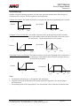
1
3401 Manual
Point I/O Stepper Module
Revision 2.0
Module Overview
The 3401 module is a one-axis stepper controller that occupies one slot in a Point I/O or a 1769-L18
system. This unit receives profile data from the PLC and outputs Step and Direction signals or
Clockwise/Counter Clockwise pulses to a stepper driver. Inputs on the module allow homing and
emergency stop operations.
The 3401 uses four 16 bit input words and eight 16 bit output words. Status information and the Current
Position data are reported to the Input Registers. The 8 output registers have two purposes. First, they are
used to configure the module with parameters such as Output Type, Homing Type, Inputs Used, Input Active
Level, and Starting Speed. Second, they are used to send the move commands, along with the distance,
speed, and acceleration and deceleration rates used to define the move profile.
32-bit parameters are divided into two words, MSW and LSW. The upper word (MSW) has the 1000s
places and the lower word (LSW) has the 1s, 10s and 100s places. Negative values are handled by setting
both the upper and lower words independently negative. For example:
Value
-12,345
12,000
-12,000
345
-345
MSW
-12
12
-12
0
0
LSW
-345
0
0
345
-345
Because the 3401 module does not use a non-volatile memory, it must be configured at every power up.
The 3401 module is not shipped with the 1734-TB (screw clamp) or the 1734-TBS (spring clamp) wiring
base assembly. These parts must be separately ordered from Rockwell Automation.
Sample programs showing how to program the 3401 module are available from the following page of our
website.
http://www.amci.com/sampleprograms.asp
Driver files that can be used to add the 3401 module to ControlNet, DeviceNet, or Profibus systems can
be downloaded from the following page of our website.
http://www.amci.com/driverfiles.asp
20 Gear Drive, Plymouth Industrial Park, Terryville, CT 06786
Tel: (860) 585-1254 Fax: (860) 584-1973 E-mail: Sales @amci.com
page: 1
3401 Manual
Point I/O Stepper Module
Revision 2.0
General Information
Important User Information
The products and application data described in this manual are useful in a wide variety of different
applications. Therefore, the user and others responsible for applying these products described herein are
responsible for determining the acceptability for each application. While efforts have been made to
provide accurate information within this manual, AMCI assumes no responsibility for the application or
the completeness of the information contained herein. Throughout this manual the following two notices
are used to highlight important points.
WARNINGS tell you when people may be hurt or equipment may be damaged if the procedure is not
followed properly.
CAUTIONS tell you when equipment may be damaged if the procedure is not followed properly. No
patent liability is assumed by AMCI, with respect to use of information, circuits, equipment, or software
described in this manual. The information contained within this manual is subject to change without
notice. UNDER NO CIRCUMSTANCES WILL ADVANCED MICRO CONTROLS, INC. BE
RESPONSIBLE OR LIABLE FOR ANY DAMAGES OR LOSSES, INCLUDING INDIRECT OR
CONSEQUENTIAL DAMAGES OR LOSSES, ARISING FROM THE USE OF ANY INFORMATION
CONTAINED WITHIN THIS MANUAL, OR THE USE OF ANY PRODUCTS OR SERVICES
REFERENCED HEREIN.
Standard Warranty
ADVANCED MICRO CONTROLS, INC. warrants that all equipment manufactured by it will be free
from defects, under normal use, in materials and workmanship for a period of [18] months. Within this
warranty period, AMCI shall, at its option, repair or replace, free of charge, any equipment covered by
this warranty which is returned, shipping charges prepaid, within 18 months from date of invoice, and
which upon examination proves to be defective in material or workmanship and not caused by accident,
misuse, neglect, alteration, improper installation or improper testing. The provisions of the “STANDARD
WARRANTY” are the sole obligations of AMCI and excludes all other warranties expressed or implied.
In no event shall AMCI be liable for incidental or consequential damages or for delay in performance of
this warranty.
Returns Policy
All equipment being returned to AMCI for repair or replacement, regardless of warranty status, must have
a Return Merchandise Authorization number issued by AMCI. Call (860) 585-1254 with the model and
serial numbers along with a description of the problem. A “RMA” number will be issued. Equipment
must be shipped to AMCI with transportation charges prepaid. Title and risk of loss or damage remains
with the customer until shipment is received by AMCI.
24 Hour Technical Support Number
Technical Support, in the form of documents, FAQs, and sample programs, is available from our website,
www.amci.com. 24 Hour technical support is also available on this product. For technical support, call
(860) 583-7271. Your call will be answered by the factory during regular business hours, Monday
through Friday, 8AM - 5PM EST. During non-business hours, an automated system will ask you to leave
a detailed message and the telephone number that you can be reached at. The system will page an
engineer on call. Please have your product model number and a description of the problem ready before
you call.
20 Gear Drive, Plymouth Industrial Park, Terryville, CT 06786
Tel: (860) 585-1254 Fax: (860) 584-1973 E-mail: Sales @amci.com
page: 2
3401 Manual
Point I/O Stepper Module
Revision 2.0
Table of Contents
Installing the 3401 Module
Chapter 1
Installing the Hardware
Module Specifications
Front Panel & LED Functions
Connector Pinout and Wiring
Installing in a 1769-L18 System
Configuring a ControlNet System
Configuring a DeviceNet System
Configuring an Ethernet System
Configuring a Profibus System
4
4
5
5
6
8
9
11
12
13
Calculating Move Profiles
Chapter 2
15
Configuration Programming
Chapter 3
Configuration Bits
Input Active Level
Starting Speed
Invalid Configurations
Configuration Mode Input Data
17
18
19
19
19
20
Command Mode Operations
Chapter 4
Absolute & Relative Moves
Hold Move
Resume Move
Immediate Stop
Find Home +/(CW), Find Home -/(CCW)
Manual Move +/(CW), Manual
Move -/(CCW)
Preset Current Position
Reset Errors
Blend Move
Acceleration Types
21
21
22
22
22
23
25
Command Mode Output Data
Chapter 5
Command Words
Command Bits
Blend Move Programming
29
29
30
31
Command Mode Input Data
Chapter 6
Status Bits
Current Position Input Word Function
Status and Error Bit Functions
Manual Revisions
34
34
35
35
38
20 Gear Drive, Plymouth Industrial Park, Terryville, CT 06786
Tel: (860) 585-1254 Fax: (860) 584-1973 E-mail: Sales @amci.com
26
26
27
28
page: 3
3401 Manual
Point I/O Stepper Module
Revision 2.0
Chapter 1: Installing the 3401 module
Disconnect power before attempting to install or remove the 3401 module.
Installation Notes
• Verify that your system’s power supply has adequate reserve current capacity. The 3401 module
requires 85mA @5Vdc
• A maximum of five (5) 3401 modules can be installed in one network base. The cause is a small
voltage drop across each of the 3401 modules, and past five modules, the voltage is too low for a 3401
module to operate. It is possible to add more 3401 modules to the Point I/O base by adding a 1734EP24DC to the system.
• Because of their on board microprocessors, the 3401 modules will become warmer than most Point I/O
modules. There is no reason to be concerned and adequate spacing around the Point I/O system to
allow convection cooling is all that is required.
• The 3401 module is not shipped with the 1734-TB (screw clamp) or the 1734-TBS (spring clamp)
mounting base assembly. These parts must be separately ordered from Rockwell Automation.
Installing the Mounting Base
1. Verify that the DIN rail locking screw is in the horizontal position. The mounting base will not attach
to the DIN rail if this screw is in the vertical position.
2. Position the mounting base vertically above any currently installed units, such as an adapter, power
supply, or an existing module.
3. Slide the mounting base down allowing the interlocking side pieces to engage the adjacent module or
adapter.
4. Press firmly until the mounting base snaps onto the DIN rail.
5. To remove the mounting base from the DIN rail, remove the 3401 module, and then use a small
bladed screwdriver to rotate the base locking screw to the vertical position. This releases the locking
mechanism holding the mounting base to DIN rail. Lift the mounting base straight up to remove.
Installing the 3401 Module into the Mounting Base
The 3401 module can be installed before or after Mounting Base has been installed. However, before
installing the module, verify that the Mounting Base is correctly keyed for the 3401 module. If it is not,
use a small bladed screwdriver to rotate the keyswitch on the mounting base until it matches keying on
the 3401 module.
Install the 3401 module by inserting it into the Mounting Base and pressing straight down. The module
will lock into place.
Installing/Removing the Removable Terminal Block (RTB)
A removable terminal block is supplied with the Mounting Base assembly. Pull up on the RTB handle to
remove. This allows the mounting base to be removed and replaced as necessary without removing any
of the wiring. Use the following procedure to reinsert the removable terminal block.
1. Insert the end opposite the handle into the base unit. This end has a curved section that engages with
the wiring base.
2. Rotate the terminal block into the wiring base until it locks itself in place.
3. If an I/O module is installed, snap the RTB handle into place on the module.
WARNING
20 Gear Drive, Plymouth Industrial Park, Terryville, CT 06786
Tel: (860) 585-1254 Fax: (860) 584-1973 E-mail: Sales @amci.com
page: 4
3401 Manual
Point I/O Stepper Module
Revision 2.0
Module Specifications
•
•
•
Pointbus Current Draw: 85mA @5Vdc
A maximum of five 3401 modules can be installed in one Point I/O base. It is possible to add
more 3401 modules to the Point I/O base by adding a 1734-EP24DC to the system.
Throughput Time: 250 µs (Inputs must be on for 250 µs to be scanned by the module)
The throughput time represents how long the 3401 module will need between
receiving a command and acting on it. It does not include the time that it will
take to transfer data to and from the 3401 module over the network.
Stepper Outputs
Output Voltage: +5Vdc differential (3.5Vdc to 4Vdc peak typical)
Maximum Output Current: 20mA
Maximum Output Frequency: 1MHz
Discrete Inputs
Input Type: Sinking
Input Voltage Range:
On = 8 to 24Vdc
Off = 0 to 2Vdc
Input Current: 15mA @ 24Vdc
Response Time (On and Off): 5µs
Input Functions: Home and Emergency Stop inputs
Environmental Conditions
Operating Temperature: 0 to 60° C
Relative Humidity: 5 to 95% (non-condensing)
Storage Temperature: -40 to 85° C
LED Function
Module
Network
Status
Limit
Input
Home
Input
Module LED
Solid Green: Module OK, no motion in progress
Blinking Green: Motion occurring
Blinking Red: Configuration Error, Command Error, Input Error, Home
Invalid Error, or an Invalid Profile Error.
Network Status
Off: No communication with scanner module
Green: Communicating with the scanner module
Red: Communication Error
Limit and Home Input LED
Orange: Indicates that the input is active. These LEDs will be ON if the
Input has been configured as Active High and is receiving power
or if the Input has been configured as Active Low and is not
receiving power.
20 Gear Drive, Plymouth Industrial Park, Terryville, CT 06786
Tel: (860) 585-1254 Fax: (860) 584-1973 E-mail: Sales @amci.com
page: 5
3401 Manual
Point I/O Stepper Module
Revision 2.0
Connector Pin Out
The following diagram shows the function of the 8 pin 1734-RTB terminal block when it is used with the
3401 module.
Pin 0
-Step or –CW output
Pin 2
-Direction or –CCW output
Pin 4
Module Common
Pin 6
Limit Input
Pin 1
+Step or +CW output
Pin 3
+Direction or +CCW output
Pin 5
Chassis Ground (shields)
Pin 7
Home Input
Home and Limit Input Wiring
The Home and Limit Inputs are sinking inputs that will be activated when you source current to them.
The following diagram shows how to wire the Home and Limit Inputs to a sourcing sensor.
Power Supply
Home (7) or Limit (6) Input
Module Common (4)
Sourcing Sensor
20 Gear Drive, Plymouth Industrial Park, Terryville, CT 06786
Tel: (860) 585-1254 Fax: (860) 584-1973 E-mail: Sales @amci.com
+ 8 to 24Vdc
Common
page: 6
3401 Manual
Point I/O Stepper Module
Revision 2.0
Wiring Notes:
•
•
•
•
•
•
•
Stepper signals are generally low voltage, low power signals. If you are using A-B guidelines for
cabling installation, treat the cable as a Category 2 cable. It can be installed in conduit along with
other low power cabling such as communication cables and low power ac/dc I/O lines. It cannot
be installed in conduit with ac power lines or high power ac/dc I/O lines.
To reduce or eliminate the influence of electrical noise on the system, the step and direction cable
shields must be connected to chassis ground terminal 5. Also, the shields must be connected to
only one end of the cable run and treated as conductors at any junctions. Do not ground the
shields at the junction box.
If the signal cable must cross power feed lines, it should do so at right angles.
Route the cable at least five feet from high voltage enclosures, or sources of “rf” radiation.
The Module Common should be connected to the COM of the supply that powers the discrete
inputs. A Stepper Driver with Single Ended Step and Direction inputs can also be referenced here.
The Chassis Ground pin is connected to the PLC’s chassis ground.
POINT I/O is grounded through the DIN rail to chassis ground. Use zinc plated, yellow chromated
steel DIN rail to assure proper grounding. Using other DIN rail materials (e.g. aluminum, plastic,
etc.) that can corrode, oxidize or are poor conductors can result in improper or intermittent
platform grounding.
20 Gear Drive, Plymouth Industrial Park, Terryville, CT 06786
Tel: (860) 585-1254 Fax: (860) 584-1973 E-mail: Sales @amci.com
page: 7
3401 Manual
Point I/O Stepper Module
Revision 2.0
Installing the 3401 module in 1769-L18 PLC
1.
2.
3.
4.
Open RSLogix 5000 and the project in which you want to install the AMCI 3401 module.
Right click on I/O Configuration in the Project Tree.
Select New Module.
Select the following module type and description from the list that appears.
Type = 1769-MODULE
Description = Generic 1769 Module
5. Click on OK.
6. Enter the following module properties.
Name: Your Choice (must begin with a letter)
Description: Your Choice
Comm Format: Data-INT (The default is Input Data-INT. This must be changed to Data-INT)
Slot: location of 3401 module
7. Enter the Connection Parameters from the following table.
Input
Output
Configuration
Assembly Instance
101
102
103
Size
6
8
0
8. Click on Next and select the RPI time. The minimum RPI time for the 3401 is 2ms.
9. The 3401 module will now appear in the project tree and three new data tags will have been
created, Local:X.I.Data[Y], Local:X.O.Data[Y] and Local:X.C.Data[Y] where “X” is the slot
number and “Y” is the word number. The status, current position, encoder position, and captured
data value are located in the Input tags. All commands are sent to the 3401 module through the
Output tags. The 3401 module does not use the Configuration tags.
Please note that the first two input words, Local:X.I.Data[0] and Local:X.I.Data[1] are not used
and will always be equal to zero.
20 Gear Drive, Plymouth Industrial Park, Terryville, CT 06786
Tel: (860) 585-1254 Fax: (860) 584-1973 E-mail: Sales @amci.com
page: 8
3401 Manual
Point I/O Stepper Module
Revision 2.0
Installing the 3401 module in a ControlNet system
1. Create or open a new Ladder Logic program.
2. If it does not already exist, add a ControlNet adapter module, such as the 1756-CNBR/D module,
to the rack configuration
3. Right click on the ControlNet adapter module and then select New Module.
4. Select the 1734-ACNR module from the list of modules that appears. The Module Properties
window will open. Enter the following parameters.
Name: Your Choice, but it must begin with a letter
Description: Your Choice
Comm Format: Rack Optimization or None
Node: Must match the address set on the 1734-ACNR adapter.
Chassis Size: One plus the number of Point I/O modules attached to the 1734-ACNR. After
changing and downloading the chassis size, go online, select the chassis tab, and click on “Set
Chassis Size in Module.”
5. If the Comm Format above was set to None, click on Finish>> to accept the configuration. If the
Comm Format above was set to Rack Optimization, click on Next> and set the RPI time for the
discrete I/O modules in your system, and then click on Finish>> to accept the configuration.
6. Right click on the 1734-ACNR module and then select New Module.
7. Select the 1734-Module as the module type. The description will be Generic 1734 module.
Enter the following parameters on the Module Properties window that opens.
Name: Your choice, but it must begin with a letter
Description: Your choice
Comm Format: Data-INT (must be Data-INT)
Slot: Location of the AMCI 3401 module. Slot 1 will be located directly to the right of the
1734-ACNR adapter.
Connection Parameters:
Input
Output
Configuration
Assembly Instance
101
102
103
Size
6
8
0
ControlLogix system will
create 198 configuration
words. These words are not
sent to the 3401 module.
8. Click on Next and select the RPI time. Because the AMCI 3401 is a Specialty I/O module, it will
only use direct connections to communicate with the scanner module. Although any value down
to 3ms can be selected, AMCI does not recommend values below 15ms. Additionally, to avoid
overloading the 1734-ACNR adapter, AB recommends that a RPI time of 50ms or greater be used
for all direct communication modules.
9. The other pages of the Module Properties window are not used by the AMCI 3401 module. Click
on Finish>> to complete the installation.
10. The following tags will have been created. The adapter name shown here was selected for the
1734-ACNR in Step 4 above. Also, X = slot number and Y = word number.
adapter_name:X:I.data[Y] Input Data sent from the 3401 module to the PLC. Words 0
and 1 will always be zero.
adapter_name:X:O.data[Y] Output Data sent from the PLC to the 3401 module.
adapter_name:X:C.data[Y] Configuration Data, not used by the 3401 module.
20 Gear Drive, Plymouth Industrial Park, Terryville, CT 06786
Tel: (860) 585-1254 Fax: (860) 584-1973 E-mail: Sales @amci.com
page: 9
3401 Manual
Point I/O Stepper Module
Revision 2.0
Because the data from the 3401 module is updated at the RPI time
asynchronously to the program scan, AMCI recommends that the input data
be buffered before it is used by the ladder logic program.
11. Save the project.
12. Download the new configuration to the processor.
RSNetWorx Setup
Although it is not required to make the 3401 module operate in a ControlNet system, adding the 3401
module’s EDS file to RSNetWorx will allow it to appear in your network. If the EDS file is not added to
RSNetWorx, then the 3401 module will appear as an Unknown Device.
The EDS file is available in the Driver File Download section of our website, www.amci.com. The
following procedure, used to add the EDS file to RSNetWorx, assumes that you have already downloaded
this file and un-zipped it.
1.
2.
3.
4.
5.
6.
7.
8.
9.
10.
11.
12.
Start RSNetWorx for ControlNet and either open an existing project or create a new one.
In the RSNetWorx program, click on Tools in the menu bar.
Click on EDS Wizard… from the pull down menu that appears.
Click on Next> in the window that appears.
Select Register an EDS file(s) and click on Next>.
Select Register and EDS file.
Click on Choose File… and navigate to the folder where you placed the un-zipped EDS file.
Double click on 3401_r01.eds file.
Click on Next>.
Click on 3401_r01.eds file so that it is highlighted.
Click on Next> to assign an icon to the device.
Click on the 3401 and then click on Change icon… and select one of the built in icons that
Rockwell Automation offers.
13. Click on Next> and then click on Finish to complete the installation of the AMCI 3401 EDS
file to the RSNetWorx system.
14. Go Online. RSNetWorx will scan the ControlNet network and should discover both the Point
I/O adapter and the 3401 module at the node address that you set on the Point I/O adapter.
15. Click on the Enable Edits checkbox and then save the project. You should now have a
working network.
20 Gear Drive, Plymouth Industrial Park, Terryville, CT 06786
Tel: (860) 585-1254 Fax: (860) 584-1973 E-mail: Sales @amci.com
page: 10
3401 Manual
Point I/O Stepper Module
Revision 2.0
Installing the 3401 module in a DeviceNet system
Before the 3401 can be attached to a network, it must be added to the RSNetWorx for DeviceNet
software. The EDS file is available in the Driver File Download section of our website, www.amci.com.
The following procedure to add the EDS file to RSNetWorx assumes that you have already downloaded
this file and un-zipped it.
Please note that the 3401 does not support ADR (Automatic Device Replacement).
1.
2.
3.
4.
5.
6.
7.
8.
9.
10.
11.
12.
Start RSNetWorx for DeviceNet.
In the RSNetWorx program, click on Tools in the menu bar.
Click on EDS Wizard… from the pull down menu that appears.
Click on Next> in the window that appears.
Select Register an EDS file(s) and click on Next>.
Select Register and EDS file.
Click on Choose File… and navigate to the folder where you placed the un-zipped EDS file.
Double click on 3401_r01.eds file.
Click on Next>.
Click on 3401_r01.eds file so that it is highlighted.
Click on Next> to assign an icon to the device.
Click on the 3401 and then click on Change icon… and select one of the built in icons that
Rockwell Automation offers.
13. Click on Next> and then click on Finish to complete the installation of the AMCI 3401 EDS file
to the RSNetWorx system.
14. Open or create a network where a 1734-ADN scanner module is present. In this network, the
scanner module will have a node address of zero.
15. Add the 3401 to your network as you would any other Point I/O module, including adding it to
the scanlist configuration of the scanner module. The 3401 module has a default node address of
63.
16. Go online with the DeviceNet network and drill down to the subnet network.
17. Expand the Point I/O network associated with the 1734-ADN PointIO DeviceNet Adapter module
and select the DeviceNet Subnet, DeviceNet network.
18. If, after the network is scanned, the 3401 module has a different address from the desired one,
right click on the module, select Properties… and change the address to the desired value. It will
also be necessary to update the Scanlist in the Scanner module. Please note that to operate
correctly, the lower numbered addresses must be located closer to the 1734-ADN Scanner
module.
19. Once the network has been correctly configured, save it, and then download it to the scanner
module.
20. Open or create a second network that will be reading the data from the Point I/O network created
above. In this network, the node number of the 1734-ADN adapter module must match what is
physically set by the address switches on the 1734-ADN adapter module.
21. Right click on the 1734-ADN module and select Properties…
22. Click on the Device Bridging Tab
23. Click on Associate File and select the file that was created above.
24. Click on Apply.
25. Once the network has been correctly configured, save it, and then download it to the network’s
scanner module.
20 Gear Drive, Plymouth Industrial Park, Terryville, CT 06786
Tel: (860) 585-1254 Fax: (860) 584-1973 E-mail: Sales @amci.com
page: 11
3401 Manual
Point I/O Stepper Module
Revision 2.0
Installing the 3401 module in an Ethernet system
10. Create or open a new Ladder Logic program.
11. If it does not already exist, add an Ethernet bridge module to the rack configuration. For example
the 1756-ENET/B module.
12. Enter the IP address, for example 192.168.001.002, and then click on Finish >> to accept the
configuration.
13. Right click on the 1756-ENET/B module and then select New Module.
14. Select the 1734-AENT/A from the list of modules that appears. The Module Properties window
will open. Enter the following parameters.
Name: Your Choice, but it must begin with a letter
Description: Your Choice
Comm Format: Rack Optimization or None
IP Address: Except for the last three digits, it must match the IP address entered in step 3 above.
The last three digits must match the node number entered on the 1734-AENT/A
adapter.
Chassis Size: One plus the number of Point I/O modules attached to the 1734-AENT/A.
(If adding the 3401 module to an existing system, the Chassis Size parameter must
also be modified on the Chassis Size tab of the 1734-AENT/A module. After
changing and downloading the chassis size, go online, select the chassis tab, and
click on “Set Chassis Size in Module.”)
15. If the Comm Format was set to None, click on Finish>> to accept the configuration. If the
Comm Format above was set to Rack Optimization, click on Next> and set the RPI time for the
discrete I/O modules in your system, and then click on Finish>> to accept the configuration.
16. Right click on the 1734-ENET/B module and then select New Module.
17. Select the 1734-Module as the module type. The description will be Generic 1734 module. The
Module Properties window will open. Enter the following parameters.
Name: Your choice, but it must begin with a letter
Description: Your choice
Comm Format: Data-INT (must be Data-INT)
Slot: Location of the AMCI 3401 module. Slot 1 will be located directly to the right of the
1734-AENT/A adapter.
Connection Parameters:
Input
Output
Configuration
Assembly Instance
101
102
103
Size
6
8
0
18. Click on Next and select the RPI time. Because the AMCI 3401 is a Specialty I/O module, it will
only use direct connections to communicate with the scanner module. Although any value down
to 3ms can be selected, AMCI does not recommend values below 10ms. Additionally, to avoid
overloading the 1734-AENT adapter, AB recommends that a RPI time of 50ms or greater be used
for all direct communication modules.
19. The other pages of the Module Properties window are not used by the AMCI 3401 module. Click
on Finish>> to complete the installation.
20 Gear Drive, Plymouth Industrial Park, Terryville, CT 06786
Tel: (860) 585-1254 Fax: (860) 584-1973 E-mail: Sales @amci.com
page: 12
3401 Manual
Point I/O Stepper Module
Revision 2.0
20. The following tags will have been created. The adapter name shown here was selected for the
1734-AENT in Step 5 above. Also, X = slot number and Y = word number.
adapter_name:X:I.data[Y] Input Data sent from the 3401 module to the PLC. Words 0
and 1 will always be zero.
adapter_name:X:O.data[Y] Output Data sent from the PLC to the 3401 module.
adapter_name:X:C.data[Y] Configuration Data, not used by the 3401 module.
Because the data from the 3401 module is updated at the RPI time
asynchronously to the program scan, AMCI recommends that the input data
be buffered before it is used by the ladder logic program.
21. Save the project.
22. Download the new configuration to the processor.
Installing the 3401 module in a Profibus system
SST-PFB-SLC Profibus interface module to AB 1734-APB
Because of the communication parameters that it stores in the module’s
memory, once a 3401 module has been used with a 1734-APB, it may not
operate in a Point I/O system that is based on a different network.
1. If it is not already present, install the SST-PFB-SLC module in the SLC rack and configure the rack
(the ID code is 13635) for the module.
2. Place the PLC in program mode.
3. Connect a serial cable from the computer’s COM port to the RS232 port of the SST-PFB-SLC
module.
4. With the power off, set the station address 1734-APB.
5. Attach the 1734-APB to the Profibus network.
6. Apply power to the 1734-APB.
7. Start the SST Profibus Configuration software.
8. Either create a new or open an existing network.
9. To use the AMCI 3401 module in a Profibus Point I/O system, it must be added to the GSD file
for the 1734-APB. There are two options.
a. Download the 1734-APB file that already contains the AMCI 3401 module. This file is
named 1734AMCI.gsd and will replace the GSD file that is currently being used to
communicate with the 1734-APB
b. Use a text editor to add the AMCI 3401 information to your existing 1734-APB GSD
file. This file is named 3401_Profibus.txt. After you have added it, register the
modified GSD file with your Profibus network software.
The ZIP file containing these two files is named AMCI_3401_Profibus.zip and are
available for download from the Tech Library section of our website, www.AMCI.com.
20 Gear Drive, Plymouth Industrial Park, Terryville, CT 06786
Tel: (860) 585-1254 Fax: (860) 584-1973 E-mail: Sales @amci.com
page: 13
3401 Manual
Point I/O Stepper Module
Revision 2.0
10. Add the GSD file to your Profibus program by clicking on Library in the toolbar and then select
Add GSD file. Choose the directory where the GSD file is located, and then select the file.
When registered this module will appear under Slaves as: Allen Bradley, 1734-APB [1.15].
11. If SST-PBF-SLC module is not already present, click on Masters. Click and drag the Master
(Rev 1.4) into the network. Right click on it and configure it according to your system’s
requirements.
12. Under slaves, click and drag the 1734-APB [1.15] module into the network. The setup window
will appear.
13. Under the General tab, set the station number to match the station number set by the switches on
the 1734-APB.
14. Click on the Modules tab and then click on Add.
15. Scroll to the bottom of the list, select AMCI 3401 Stepper, not AMCI stepper Empty Slot, and
then click on OK.
16. Click on the SLC Address tab. Select the Input data location (I type or M1) and offset and the
Output data location (O type or M0) and the offset. The AMCI 3401 module uses four sixteen
input words and eight sixteen bit outputs words. Be careful not to leave any gaps between the
address of the 3401 module and any existing modules in your system.
17. Click on OK to accept.
18. Save the network file.
19. Right click on the Master Module and select Connect from the menu that appears.
20. Click on Yes if asked to retain the configuration.
21. Again right click on the Master Module and then select Load Configuration from the menu that
appears.
22. Place the PLC in Run mode.
20 Gear Drive, Plymouth Industrial Park, Terryville, CT 06786
Tel: (860) 585-1254 Fax: (860) 584-1973 E-mail: Sales @amci.com
page: 14
3401 Manual
Point I/O Stepper Module
Revision 2.0
Chapter 2: Calculating Move Profiles
Before starting a move operation, the 3401 module completely calculates each portion of the move
profile. That is, it calculates how many steps of the move profile will be required for acceleration and
how many steps will be required for deceleration. Depending on the data used to define the move profile,
this can result in two types of velocity profiles, either a Trapezoidal Profile or a Triangular Profile.
A Trapezoidal Profile jumps from rest to the Starting Speed, accelerates to the Programmed Velocity at
the commanded acceleration rate, continues at the Programmed Velocity to a predetermined point, and
then decelerates to the target position at the commanded deceleration rate to the starting speed and stops.
Velocity
Trapezoidal Profile
Starting
Speed
Time
However, if the length of a commanded move is not long enough to attain the programmed velocity
before the deceleration point is reached, a Triangular Velocity profile will be generated.
Velocity
Triangular Profile
Starting
Speed
Time
Regardless of the type of Velocity Profile that is being run, the following equations can be used to
determine both the time to accelerate and the number of steps needed to accelerate. These formulas can
also be used to calculate the time and distance to decelerate.
Ta = (Vs – Vo)/a
Da = Ta * (Vo + Vs)/2
Vo = Starting Speed (steps/second)
Vs = Programmed Speed (steps/second)
Ta = Time to accelerate (seconds)
Da = Distance to accelerate (steps)
a = Acceleration rate (steps/second/second)
Velocity
Vs
Vo
Time
If using Triangular S Curve Acceleration, Ta = 2 * Ta calculated above
If using Trapezoidal S Curve Acceleration, Ta = (4/3) * Ta calculated above
The acceleration rate entered in these equations must have units of steps/second/second, not the
steps/ms/second used by the 3401 module. See the Calculation Notes below for a complete explanation.
20 Gear Drive, Plymouth Industrial Park, Terryville, CT 06786
Tel: (860) 585-1254 Fax: (860) 584-1973 E-mail: Sales @amci.com
page: 15
3401 Manual
Point I/O Stepper Module
Revision 2.0
Calculation Notes
1. The acceleration and deceleration values sent to the 3401 module as part of the move profile have
units of steps/ms/sec.
If you are using the above formulas to calculate Ta (the time to accelerate), multiply the
acceleration value sent to the 3401 module by 1000 before using it in the formulas.
If you are using the above formulas to calculate the acceleration rate from a desired Time to
accelerate, divide the result of the calculation by 1000 before using it as the acceleration
parameter sent to the 3401 module.
2. If the number of steps to accelerate plus the number of steps to decelerate is greater than the
number of steps programmed in the target position registers, than the 3401 module will run a
Triangular Velocity Profile.
3. If the number of steps to accelerate plus the number of steps to decelerate is less than the number
of steps programmed in the target position, than the 3401 module will run a Trapezoidal Velocity
Profile.
Velocity
Vs
Starting
Speed
Da
Ds
Dd
Tt
Ds = (Total Number of Steps) – (Da + Dd)
Tt = Ta + Td + Ds/Vs
Da = Distance to Accelerate (steps)
Ds = Distance at the programmed speed (steps)
Dd = Distance to decelerate (steps)
Vs = Programmed Speed (steps/sec)
Tt = Total Profile Time (seconds)
Starting Speed
The starting speed has a range of 1 to 1,000,000 pulses/sec and is the pulse frequency at which every
move begins and ends. That is, the first and last pulses of the move profile will be at the starting speed.
Although it is not necessary, the smoothest transition from rest to the programmed speed will be achieved
with a Starting Speed equal to the square root of the acceleration value.
20 Gear Drive, Plymouth Industrial Park, Terryville, CT 06786
Tel: (860) 585-1254 Fax: (860) 584-1973 E-mail: Sales @amci.com
page: 16
3401 Manual
Point I/O Stepper Module
Revision 2.0
Chapter 3: Configuration Programming
Configuration Mode
The Configuration Mode provides the ability to select the proper setup configuration to match the stepper
application without having to set any switches. The configuration file, consisting of four 16-bit words,
allows the following parameters to be defined.
1.
2.
3.
4.
5.
6.
7.
8.
9.
If the Limit Input will as and Emergency Stop Input
If the Limit Input will be used as a CW End Limit Switch
If the Limit Input will be used as a CCW End Limit Switch
If CW Homing Operations will be allowed
If CCW Homing Operations will be allowed
If a Backplane Home Proximity bit will be part of the homing operations
The output type, either CW and CCW Pulses or Pulse and Direction
The Limit Input and Home input active state
The Starting Speed. The starting speed is the pulse frequency at which every move begins and end.
Some portions of the homing operations are also performed at the starting speed.
10. The Starting Speed. The starting speed is the pulse frequency that every move begins and ends at.
Some portions of the homing operations are also performed at the starting speed.
Configuration Mode Output Data
(Eight 16 bit words sent from the PLC to the 3401 module)
While in configuration mode, the output registers have the following format.
16 bit output
Word
0
1
2
3
4
5
6
7
Configuration
Output Data
Configuration Bits MSW
Configuration Bits LSW
Starting Speed MSW
Starting Speed LSW
0
0
0
0
Units
Range
See description below
See description below
Steps/Second
1 to 1,000,000
Note 1: The module will power up in Command Mode showing a Configuration Error. The
Configuration Error bit will remain set as long as valid configuration data has not been written to
the module.
Note 2: If Configuration Mode is entered while a move is occurring, the Command Error bit will be set,
the move will run to completion, and then the module will enter Configuration Mode.
Note 3: The Starting Speed is programmed in two words. The MSW contains the 1000 places and the
LSW contains the 1s, 10s, and 100s places of the value. For example, if the starting speed is
12,345 steps/sec, than the MSW would 12 and the LSW would be 345.
20 Gear Drive, Plymouth Industrial Park, Terryville, CT 06786
Tel: (860) 585-1254 Fax: (860) 584-1973 E-mail: Sales @amci.com
page: 17
3401 Manual
Point I/O Stepper Module
Revision 2.0
Configuration Bits MSW
Bit 0: Set when the Limit Input is configured to be used as an Emergency Stop input. When this bit
is set, an active Limit Input will immediately stop all motion.
Bit 1: Set when the Limit Input is configured to be used as a CW Over Travel Limit Switch. When
this bit is set, an active Limit Input will stop Absolute, Relative, and Blend Move profiles. It
will also stop CW Manual Move operations, but not CCW Manual Move operations. If the
Limit Input is reached during a CW Home operation, the direction of motion will be reversed
and the 3401 module will search for the home input in the CCW direction.
Bit 2: Set when the Limit Input is configured to be used as a CCW Over Travel Limit Switch.
When this bit is set, an active Limit Input will stop Absolute, Relative, and Blend Move
profiles. It will also stop CCW Manual Move operations, but not CW Manual Move
operations. If the Limit Input is reached during a CCW Home operation, the direction of
motion will be reversed and the 3401 module will search for the home input in the CW
direction.
Bit 3: Reserved for future use
Bit 4: Set when a CW Homing Operations will be allowed. If this bit is reset, issuing a CW Home
command will generate a Home Invalid error.
Bit 5: Set when a CCW Homing Operations will be allowed. If this bit is reset, issuing a CCW
Home command will generate a Home Invalid error.
Note: It is possible to set both bits 4 and 5, only one of the two bits, or to not set either of
the bits.
Bit 6: set for backplane Home Proximity operations (this bit can only be set if bits 4 or 5 are used)
The 3401 can be configured to ignore changes on the physical home input until the Home
Proximity Bit makes a 0 to 1 transition. The 3401 will home on the next inactive to active
change of the physical home input once this transition occurs. You must program your PLC to
control the state of this bit. Do not set this bit if you want to home only to the home input.
Bit 7: “1” when output pulse type is pulse train and direction
“0” when output pulse type is CW pulse train and CCW pulse train
Bits 8 to 14: Reserved for future use
Bit 15: “1” for configuration mode operations, “0” for command mode operations
AMCI feels that it is dangerous to home in a direction that does not
have an End Limit Switch configured. Configuration Bits 4 and 5 were
created to ensure that the user is aware of this warning when selecting
the configuration bits. Even though it is not recommended, it is
possible to configure the 3401 module to home in a direction that does
not have an end limit switch configured.
Configuration Bits LSW (Defines the Input Active Level of the Limit and Home Input)
Bit 0: determines the active level of the Limit Input configured to be used as an E-Stop Input
Bit 1: determines the active level of the Limit Input configured to be used as a CW over travel limit
switch
Bit 2: determines the active level of the Limit Input configured to be used as a CCW over travel limit
switch
Bit 3: determines the active level of the Home input
Bits 4 to 15: Reserved for future use, must be zero
20 Gear Drive, Plymouth Industrial Park, Terryville, CT 06786
Tel: (860) 585-1254 Fax: (860) 584-1973 E-mail: Sales @amci.com
page: 18
3401 Manual
Point I/O Stepper Module
Revision 2.0
Input Active Level
This parameter defines the active level of the inputs. These bits will be set for high level active, Normally
Open (NO), or reset for low level active or Normally Closed (NC). High-level active means that
supplying current to the input will activate it. Low-level active means that removing current from the
input will activate it.
Please note that only one of bits 0, 1, and 2 can be set at one time and that the active level bits can only be
set when the input has been selected in configuration word 0.
The inputs to the 3401 module are always sinking. That is, to operate they must be connected to sensors
that source current.
Starting Speed
The starting speed has a range of 1 to 1,000,000 pulses/sec and is the pulse frequency at which every
move begins and ends. That is, the first and last pulses of the move profile will be at the starting speed.
Some portions of the homing operations are also performed at the starting speed.
Note 1: Although it is not necessary, the smoothest transition from rest to the programmed speed
will be achieved with a Starting Speed equal to the square root of the acceleration.
Note 2: A lower starting speed will also increase the length of time between moves.
Invalid Configurations
The 3401 module will not accept all possible configurations. The following is a list of the invalid
configurations:
1.
2.
3.
4.
5.
6.
7.
If more than one of the bits that determine the function of the Limit Input are set at one time. This
refers to bits 0, 1, and 2 in configuration word 0.
Selecting the use of the Backplane Home Proximity bit without allowing either CW or CCW
homing by setting bit 4 and or 5 in Configuration word 0.
Selecting any of the Input Active level bits in Configuration word 1 without first selecting that the
input will be used in Configuration word 0. This also includes selecting the active state of the
home input without allowing either CW or CCW homing.
A starting speed outside the range of 1 < starting speed < 1,000,000.
If the lower word of the starting speed is outside of the range of 0 to 999.
Setting any of the unused bits in either word 0 or word 1 of the configuration data.
Setting any of the unused words to a value other than zero.
The 3401 module has to be configured before starting any operations. When the Configuration Mode flag
is set in the output registers, the stepper controller enters Configuration Mode. When in this mode, the
stepper controller will stop its operations and set the Configuration Mode flag in the input registers. It
then waits for the configuration file to be transferred. If there is no current Configuration File present or
if the transferred Configuration File is not valid, the Configuration Error Input bit will be set. If the
transferred configuration file is accepted, and if it is different from the current configuration, the
configuration data will be mirrored in the input registers.
20 Gear Drive, Plymouth Industrial Park, Terryville, CT 06786
Tel: (860) 585-1254 Fax: (860) 584-1973 E-mail: Sales @amci.com
page: 19
3401 Manual
Point I/O Stepper Module
Revision 2.0
Configuration Mode Input Data
(Four 16 bit words sent from the 3601 module to the PLC)
While in configuration mode, the input registers will mirror the configuration data that was sent to the
3401 module in the output registers. The exceptions are the Module OK bit, input word 0, status bit 14
and the Configuration Error bit, input word 0, status bit 13.
16 bit Input
Word
0
1
2
3
ControlLogix ControlNet,
Ethernet Systems, &
1769-L18 Systems
0
1
2
3
4
5
Configuration Input Data
Always Zero
Always Zero
Mirror of Configuration Bits MSW
Mirror of Configuration Bits LSW
Mirror of Starting Speed MSW
Mirror of Starting Speed LSW
Note: Input Word 0, bits 13 to 15 are not mirrored. These three bits always function as status bits,
regardless of whether the 3401 module is in Configuration or Command mode.
20 Gear Drive, Plymouth Industrial Park, Terryville, CT 06786
Tel: (860) 585-1254 Fax: (860) 584-1973 E-mail: Sales @amci.com
page: 20
3401 Manual
Point I/O Stepper Module
Revision 2.0
Chapter 4: Command Mode Operations
The following is a description of the various commands that the module accepts and the operations that it
will perform while in Command Mode. When switching from Configuration Mode to Command Mode,
the position will be invalid and the Current Position will be zero.
Absolute/Relative Move
The current position must to be valid in order to perform an ABSOLUTE MOVE. A HOME or PRESET
operation will have to be performed before the position becomes valid. The distance moved, that is the
number of pulses issued by the 3401, is equal to the difference between the Target Position and the
Current Position. For example, if the Current Position is 5000, and the Target Position is 7500, than the
unit will output 2500 pulses. After the Absolute Move has been completed, the Current Position will be
7500. The direction of motion of an Absolute Move is determined by the relationship between the
Current Position and Target Position. If the Target Position > Current Position, than CW motion will
occur. If the Target Position < Current Position, than CCW motion will occur.
The current position does not have to be valid to perform a RELATIVE MOVE. The Target Position
defines the distance, in number of pulses, to travel relative to the Current Position. For example, if the
Current Position is 5000 and the Target Position is 7500, than the unit will output 7500 pulses. After the
Relative Move has been completed, the Current Position will be 12,500. The direction of motion of a
Relative Move is selected by the sign of the Target Position. A positive Target Position will generate a
CW move while a negative Target Position will generate a CCW move.
The ABSOLUTE or RELATIVE MOVE operations can produce two different velocity profiles.
Normally the move operations start at the Starting Speed, accelerate to the Programmed speed at the
defined acceleration rate, continue at the Programmed speed until it is time to decelerate back to the
Starting Speed, and Stop. This generates a trapezoidal velocity profile.
However, if the move operation does not reach the Programmed speed by the time the deceleration is to
begin, the move is decelerated to the Starting Speed and Stopped. In this way a triangular velocity profile
is generated.
If the move operation runs to completion without error, the MOVE COMPLETE FLAG is set. If an error
does occur, the MOVE COMPLETE FLAG will not be set, and an error flag will be set.
20 Gear Drive, Plymouth Industrial Park, Terryville, CT 06786
Tel: (860) 585-1254 Fax: (860) 584-1973 E-mail: Sales @amci.com
page: 21
3401 Manual
Point I/O Stepper Module
Revision 2.0
Hold Move
The HOLD MOVE command causes the move operation to decelerate at the programmed deceleration
rate to the Starting Speed and stop. When this operation is successfully performed, the Hold State Input
Bit is set. While the Hold operation is in affect, the velocity and acceleration deceleration parameters can
be changed, however, entering a new position will have no affect. If no error occurred during the stop
operation, the RESUME MOVE command can be used to restart the move operation.
•
•
•
•
•
•
•
A Command Error will be generated if not all of the other command bits are reset when the Hold
Command is issued.
Any command, including an entirely new move command, can be issued while the 3401 module is
in a Hold State. The module does not require that the Resume command be the next command
issued after the Hold command.
Output words 1 to 7 do not have to be zero when the Hold command is issued.
Because the module is already decelerating, it will ignore a Hold Move command issued during
the deceleration part of the profile.
Homing operations cannot be held. If a Hold Move command is issued during a home operation, a
Command Error will be generated and remain while the home will run to completion.
Blend Moves cannot be held. If a Hold Move command is issued while a Blend Profile is running,
the module will generate a command error, motion will continue until the profile is complete,
when the Command Error bit will be reset.
A Hold Move command issued during a manual move generates a command error and will cause
the motion to stop.
Resume Move
The RESUME MOVE command resumes a previously held Absolute or Relative Move. If the Resume
Move command is the first command issued after a Hold Move operation, and no errors have occurred,
the Resume Move command will cause the stepper motor to restart from the point where it was stopped,
and the Hold State Input Flag be reset. If Triangular S Curve or Trapezoidal S Curve acceleration is
required, the appropriate acceleration type bit(s) must be set with the Resume Move bit. When the move
operation has been successfully completed, the Move Complete Flag will be set.
The velocity, acceleration, and deceleration parameters must be present when the Resume Command is
issued.
A move operation can be held and resumed many times until one of the following has occurred:
1. The move reaches its programmed target position
2. An error condition has occurred
3. Some other command is issued
Immediate Stop
The Immediate Stop command causes the current move operation to stop without any deceleration. The
pulse signal is simply stopped. If the channel was moving when this command was issued, the current
position will become invalid, and the Position Invalid Input Bit will be set. The channel will have to be
Preset or Homed again before an Absolute Move operation can be performed. However, it will be
possible to perform a Relative Move or a Manual Move after an Immediate Interrupt has occurred. There
will be no changes to the status bits if the Immediate Stop command is issued when there is no motion
occurring,
20 Gear Drive, Plymouth Industrial Park, Terryville, CT 06786
Tel: (860) 585-1254 Fax: (860) 584-1973 E-mail: Sales @amci.com
page: 22
3401 Manual
Point I/O Stepper Module
Revision 2.0
Find Home +/(CW), Find Home -/(CCW)
There are two homing options available. They are,
1. Home Limit Switch Only
2. Home Limit Switch with a backplane Home Proximity bit.
When the homing operation is complete, the 3401 will set the At Home input bit, and then resets the
current position to zero.
The Find Home commands require that the 3401 module has been configured to allow homing in the
specified direction. The 3401 will not accept a Find Home +/(CW) command when it has not been
configured to allow CW homing (Configuration word 0, bit 4). Likewise, it will not accept a Find Home
-/(CCW) command when it has not been configured to allow CCW homing (Configuration word 0, bit 5).
If either of these operations are attempted, the HOME INVALID Error bit will be set.
S-Curve acceleration profiles are not allowed during a homing operation. Initiating a home operation
with S curve accelerations will cause a command error to be generated.
If the Limit Input is reached during a homing operation, and if the direction of homing matches the
configuration of the Limit Input (CW Over Travel Limit Switch and a CW homing operation), then the
module will stop outputting pulses (essentially an emergency stop), wait for two seconds, reverse
direction, and start searching for the appropriate homing signal again. It is important not to have the
velocity set to high during a homing operation. The sudden stop and change in direction at high speeds
may cause the motor to lock up.
If the opposite Limit Input is reached during a homing operation (CCW Over travel Limit Switch and a
CW homing operation or the CW Over travel Limit Switch and a CCW homing operation), then the
module will stop outputting pulses and set the Input Error, Home Invalid, and the Position Invalid Error
bits.
It is possible to home off of an active Over Travel Limit Switch. For example, you can perform a CW
home operation if the CCW Over Travel Limit Switch is active.
The following diagrams illustrate the different homing options.
Home Limit Switch Only
2. Runs at the
programmed speed
1. Accelerates to
programmed speed
3. Detects the Home Limit
Switch
4. Decelerates to stop
and waits 2 seconds.
5. Accelerates to the programmed
speed opposite to the requested
direction
6. Decelerates when the Home
Limit Switch goes On then
Off. Waits 2 seconds
7. Returns to the Home Limit
Switch at the starting speed
20 Gear Drive, Plymouth Industrial Park, Terryville, CT 06786
Tel: (860) 585-1254 Fax: (860) 584-1973 E-mail: Sales @amci.com
page: 23
3401 Manual
Point I/O Stepper Module
Revision 2.0
Backplane Home Proximity Bit with Home Limit Switch
1. Accelerates to
programmed speed
2. Runs at the
programmed speed
4. Detects backplane proximity bit and
decelerates to the starting speed.
5. Runs at the starting speed.
6. Detects Home Limit
Switch and stops.
Reaching an End Limit Switch During a Homing Operation
1. Runs at the Programmed Speed
2. Reaches the end Limit Switch,
stops without deceleration, and
waits for two seconds
4. Waits for the Home
Input to turn On then
Off.
3. Turns at the programmed speed opposite
to the requested direction
5. Returns at the starting speed to where the Home
Input was detected. Continues to Marker Pulse or
Home Limit Switch if applicable.
Note: The Home Input shown above can be either the Home Limit Switch or the Backplane Proximity bit.
Home Limit Switch Active when the Home Command is issued
1. Home Limit Switch
Active (gray used to
indicate width of home
limit switch)
2. Turns at the programmed speed in the direction
opposite to the requested homing operation until the
home limit switch turns off
3: Decelerates when
the Home Limit
Switch turns off
4. Returns at the starting speed to
where the home limit switch
was detected
20 Gear Drive, Plymouth Industrial Park, Terryville, CT 06786
Tel: (860) 585-1254 Fax: (860) 584-1973 E-mail: Sales @amci.com
page: 24
3401 Manual
Point I/O Stepper Module
Revision 2.0
End Limit Switch Active when the Home Command is issued
3. Home input is detected
going on and off
2. Motor turns at the programmed speed in the
direction opposite of the requested homing operation
4. Motor decelerates
and stops
1. End Limit Switch active when home
command is issued
5. Runs at the starting speed until the
home input again turns on. Continues
to Marker Pulse if applicable.
Note 1: The Home Input shown above can be either the Home Limit Switch or the Backplane Proximity
bit.
Note 2: The above diagram is only true if the active End Limit Switch is the same as the issued home
command, for example if the CW Limit Switch is active and a CW home command is issued. If
the CW Limit Switch is active and a CCW home command is issued, than the unit will home
normally, as if the end limit switch was not active.
Manual Move +/(CW), Manual Move -/(CCW)
This command performs the Manual Move operation at the programmed speed in the specified direction.
Motion will occur as long as the command bit remains set. The Target Position register must be zero
during all Manual Move operations.
If the programmed speed is less than or equal to the starting speed, the starting speed is not used and the
acceleration and deceleration parameters are ignored. The motor will “jump” to and run at the
programmed speed without any acceleration. The speed cannot be changed when the module is running
in this “constant speed mode.” If it is, a Command Error and an Invalid Profile Error will be generated
and the motion will be stopped.
If the programmed speed is greater than the starting speed, the axis begins the move at the starting speed,
accelerates until the programmed speed is reached, and continues to move at the programmed speed until
one of the following occurs:
-The Manual Move command bit is turned off
-The Immediate Stop output bit is set
-The Emergency Stop Input is activated
-The End Limit Switch in the same direction as the motion is reached
-The Programmed speed Changes
If the Manual Move command bit is turned off, the axis will decelerate at the programmed rate to the
starting speed and stop, retaining a valid position. If the Immediate Stop Output bit or the Emergency
Stop Input is used, the axis will stop without deceleration and the position will become invalid.
If the initial programmed speed is greater than the starting speed, the speed of a Manual Move operation
can be changed without stopping the motion. If the velocity data is changed while the axis is moving, the
module will accelerate or decelerate to the new speed, which can be less than the starting speed. The
20 Gear Drive, Plymouth Industrial Park, Terryville, CT 06786
Tel: (860) 585-1254 Fax: (860) 584-1973 E-mail: Sales @amci.com
page: 25
3401 Manual
Point I/O Stepper Module
Revision 2.0
acceleration and or the deceleration parameters can also be changed, although these changes do not take
affect until the programmed speed is changed. Both the acceleration and deceleration parameters must be
valid when the speed is changed. If the changed velocity, acceleration, or deceleration parameters are
invalid, motion will stop, command and invalid profile errors will be generated, and the position will
become invalid.
An additional feature of the Manual Move parameter is the ability to do a One Shot Manual Move. With
the programmed speed set to zero, a 0 → 1 transition of the Manual Move bit will cause the stepper
controller to output 1 pulse in the specified direction. Please note that in One Shot Manual Move mode,
the Motion Direction bit will remain on and the Status LED will flash as long as the Manual Move
command bit remains set. The Stopped status bit will not be set when the Manual Move command bit is
reset.
If the End Limit Switch in the same direction as motion is reached during a Manual Move, the axis will
stop without deceleration and the input error and position invalid input bits will be set. For example,
reaching the CW Limit Switch during a CW Manual Move will stop the motion. However, an End Limit
Switch in the direction opposite to motion will not stop a Manual Move operation. For example, reaching
the CCW Limit Switch during a CW Manual Move. This feature allows the module to be moved off of
an active end limit switch.
Preset Current Position
This command will set the Current Position to the value present in the Target Position Registers. If the
position is currently invalid, presetting the position will cause the position to become valid. The
programmed speed, acceleration, and deceleration parameters must be zero when this command is sent to
the module.
The Preset Current Position command also resets the Move Compete input bit.
Reset Errors
This command clears all nonfatal errors detected by the stepper controller. A nonfatal error is one that
can be recovered from. For example, requesting an Absolute Move when the position is not valid is a
nonfatal error. The Lower Command Word must be zero when the Reset Errors command is issued.
When there is a Command Error, the controller will not perform any other operations until the Reset
Errors command is issued.
General Command Mode Information:
1. Only a 0 → 1 transition of any of the command bits listed above will cause the specified operation to
occur. If a command it to be issued more than once, then the 3401 module must see the Command bit
go to zero for at least one program scan before it will act on the second move command.
2. With the exception of the acceleration type and backplane proximity bits, only one command bit should
be set at any one time.
20 Gear Drive, Plymouth Industrial Park, Terryville, CT 06786
Tel: (860) 585-1254 Fax: (860) 584-1973 E-mail: Sales @amci.com
page: 26
3401 Manual
Point I/O Stepper Module
Revision 2.0
Blend Move
This command allows the user to create more complicated move profiles consisting of two to sixteen
segments, as the following diagram illustrates.
2. Accelerates from the starting speed
to the first programmed speed using
the first programmed rate and type
3. Runs at the first
programmed target
speed
4. Runs at the final
programmed speed
5. Decelerates to the starting
speed using the final segment
deceleration parameter and
stops
Velocity
1. Jumps to the
starting speed
Position
Each segment is defined by four parameters:
1.
2.
3.
4.
Acceleration Type (Constant, Triangular S Curve, or Trapezoidal S curve)
Relative Segment Length
Target speed
Acceleration/Deceleration Rate
The minimum amount of information necessary to define a new move segment is the Target Speed. The
Segment Length and the Acceleration/Deceleration rate do not have to change from one segment to the
next. An Invalid Profile Error will be generated if the Target Speed parameter is not different in two
consecutive blend move segments.
The blend move programming is done at one time, with the segments of the blend move profile stored in
the internal memory of the 3401. This data will remain in the module’s memory until power is removed
from the module, the configuration data is programmed, or a new blend move profile is sent to the unit.
The Blend Move Profile is programmed as a series of Relative Moves (segments), so the position does
not have to be valid for the blend move operation to take place. The first segment starts at the Starting
Speed and accelerates to the specified Programmed speed. The starting speed for the next segment is
equal to the programmed speed of the current segment. The final segment will decelerate from the final
programmed speed to the starting speed and then stop. It is not possible to program a direction reversal in
the blend move profile.
Programming the configuration data will clear a stored blend move profile from the 3401 modules
memory.
Because the 3401 module stores the data for the Blend Move Profile in its memory, the programmed
profile can be run more than once and from any location. Two command bits allow the blend move
profile to be run in either direction. Please note that it is possible to perform other move or home
operations between performing the blend move profiles.
20 Gear Drive, Plymouth Industrial Park, Terryville, CT 06786
Tel: (860) 585-1254 Fax: (860) 584-1973 E-mail: Sales @amci.com
page: 27
3401 Manual
Point I/O Stepper Module
Revision 2.0
Acceleration Types
With the exception of homing operations, all of the move operations defined above allow the type of
acceleration to be selected. The three options are described below.
Constant Acceleration: The module accelerates at a constant rate until the programmed speed is reached.
Velocity
Acceleration
T
T
Time
Time
Triangular S Curve Acceleration: The module accelerates slowly at the beginning of the acceleration,
faster at the middle of the acceleration, and again slowly at the end of
the acceleration. The acceleration rate is never constant.
Acceleration
Velocity
T
T/2
Time
Time
T/2
Trapezoidal S Curve Acceleration: The module accelerates slowly at the beginning of the acceleration, at
a constant rate at the middle of the acceleration, and again slowly at
the end of the acceleration.
Velocity
Acceleration
T
Time
T/4
T/2
T/4
Time
Notes:
1. The defined acceleration type is also applied to the deceleration.
2. Constant acceleration has the shortest acceleration time and Triangular S Curve has the longest
acceleration time.
3. The constant portion of the Trapezoidal S Curve Acceleration is 50% of the total acceleration time.
20 Gear Drive, Plymouth Industrial Park, Terryville, CT 06786
Tel: (860) 585-1254 Fax: (860) 584-1973 E-mail: Sales @amci.com
page: 28
3401 Manual
Point I/O Stepper Module
Revision 2.0
Chapter 5: Command Mode Output Data
(Eight 16 bit words sent from the PLC to the 3401 module)
All stepper motor operations are performed in command mode. This mode is entered, after a successful
configuration file has been transferred to the stepper controller, by resetting the Mode Flag bit 15 of
Output Word 0. In Command Mode, the PLC program can issue commands and activate different
operations or moves. A move profile typically consists of a Target Position, Programmed Speed,
Acceleration, and Deceleration parameters. The following table shows the function of the output words.
16 bit Output
Word
0
1
2
3
4
5
6
7
1.
2.
3.
4.
Function
Command MSW
Command LSW
Target Position MSW
Target Position LSW
Programmed Speed MSW
Programmed Speed LSW
Acceleration
Deceleration
Units
Steps
Steps/Second
Steps/ms/sec
Steps/ms/sec
Range
See description below
See description below
-8,388,608 to 8,388,607
Starting Speed to
1,000,000
1 to 2000
1 to 2000
Command Mode Programming Notes
Only a single bit can be set at any one time in the Most Significant Command Word.
A Command Error will be generated if a move operation is started before the previous move
operation is completed. A move operation should only be started if the Move Complete, Stopped,
or Hold status bits are set.
The Target Position and Programmed Speed parameters are divided into two words, MSW and
LSW. The upper word (MSW) has the 1000s places and the lower word (LSW) has the 1s, 10s
and 100s places
A negative Target Position value will be programmed as a negative decimal number in both the
MSW and LSW data words. For example;
Value
-12,345
12,000
-12,000
345
-345
MSW
-12
12
-12
0
0
LSW
-345
0
0
345
-345
5. The Position parameter has a range of -8,388,608 < Target Position < 8,388,607.
6. The LSW of the Target Position has a range of –999 to +999.
7. The Programmed Speed has a range of Starting Speed < Programmed Speed < 1,000,000
steps/sec.
8. The LSW of the Programmed Speed has a range of 0 to 999.
9. The acceleration and deceleration parameters have a range of 1 < acceleration/deceleration <
2,000 and is measured in steps/msec/sec. Multiply the acceleration rate by 1000 to convert it
from steps/ms/sec to steps/sec/sec.
10. Switching the PLC to Program Mode will cause any move operation to stop and the position to
become invalid.
20 Gear Drive, Plymouth Industrial Park, Terryville, CT 06786
Tel: (860) 585-1254 Fax: (860) 584-1973 E-mail: Sales @amci.com
page: 29
3401 Manual
Point I/O Stepper Module
Revision 2.0
Command Word MSW
Bit 0 = set to perform an ABSOLUTE MOVE operation
Bit 1 = set to perform a RELATIVE MOVE operation
Bit 2 = set to perform a HOLD MOVE operation
Bit 3 = set to perform a RESUME MOVE operation
Bit 4 = set to perform an IMMEDIATE STOP operation
Bit 5 = set to perform a FIND HOME +/(CW) operation
Bit 6 = set to perform a FIND HOME -/(CCW) operation
Bit 7 = set to perform a MANUAL MOVE +/(CW) operation
Bit 8 = set to perform a MANUAL MOVE -/(CCW) operation
Bit 9 = set to PRESET the Current Position (This function also resets the Move Complete input bit)
Bit 10 = reserved
Bit 11 = set to perform a RESET ERRORS operation
Bit 12 = set to RUN BLEND MOVE PROFILE in the positive direction
Bit 13 = set to RUN BLEND MOVE PROFILE in the negative direction
Bit 14 = reserved;
Bit 15 = MODE FLAG: "1" for Configuration Mode "0" for Command Mode
Command Word LSW
Bit 0 = reset for CONSTANT ACCELERATION, set for S-CURVE ACCELERATION
Bit 1 = reset for TRIANGULAR S-CURVE ACCELERATION, set for TRAPOZOIDAL S-CURVE
ACCELERATION. This bit is only valid if bit 0 of the LSW is set.
Bits 2 to 7 = Reserved
Bit 8 = set to PROGRAM a BLEND MOVE PROFILE. This bit must remain on while the Blend
Move Profile segments are being programmed.
Bit 9 = BLEND MOVE TRANSMIT bit
Bits 10 and 11 = Reserved
Bit 12 = Back plane Home Proximity bit.
The 3401 module will ignore the state of this bit unless the module was configured to
accept backplane home proximity operations, and if there is no homing operation taking
place.
If the 3401 has been configured to use the Backplane Proximity Bit, the 3401 module will
ignore any transitions on the home input until the PLC has set this bit.
Bits 13 to 15 = Reserved.
Note: The bits in the LSW must be reset when single bit commands in the MSW are issued. For
example, the LSW must be zero when the RESET ERRORS command is issued.
20 Gear Drive, Plymouth Industrial Park, Terryville, CT 06786
Tel: (860) 585-1254 Fax: (860) 584-1973 E-mail: Sales @amci.com
page: 30
3401 Manual
Point I/O Stepper Module
Revision 2.0
Blend Move Programming
A Blend Move consists of two to sixteen segments consisting of a Relative Segment Length, a Target
Velocity, the Acceleration and Deceleration parameters. The blend move operation will be run each time
bit 12 or 13 in the output Command Word MSW 1 transitions from 0 to 1.
When bits 8 and 9 of the Command LSW are first activated, the module reads the first part of the
programming block for the blend move operation and activates the BLEND MOVE ACKNOWLEDGE
bit 9 of Status LSW. With bit 8 staying ON deactivating of bit 9 (BLEND MOVE DATA VALID) causes
deactivating of the BLEND MOVE ACKNOWLEDGE. Each additional transition of the bit BLEND
MOVE DATA VALID from 0 to 1 makes the module to read a consecutive part of the blend move
programming data for the next segment.
The following table shows the layout of the Blend Move data sent to the module.
BLEND MOVE DATA – FIRST PROGRAMMING BLOCK
Word
0
1
2
3
4
5
6
7
Function
Command word MSW
Command word LSW
Number of Segments
Acceleration Type MSW
(segments 9 to 16)
Acceleration Type LSW
(segments 1 to 8)
Final Segment Deceleration
& Acceleration Type
0
0
BLEND MOVE DATA – PROGRAMMING BLOCKS 2…17
Word
0
1
2
3
4
5
6
7
Function
Command word MSW
Command word LSW
Segment Length MSW
Segment Length LSW
Target Speed MSW
Target Speed LSW
Acceleration/Deceleration
0
Number of Segments
This parameter defines the number of blend move segments that are being programmed. This parameter
has a range of 2 to 16. A value outside of this range will generate an Invalid Profile Error.
20 Gear Drive, Plymouth Industrial Park, Terryville, CT 06786
Tel: (860) 585-1254 Fax: (860) 584-1973 E-mail: Sales @amci.com
page: 31
3401 Manual
Point I/O Stepper Module
Revision 2.0
Segment Length Restrictions
•
•
•
The sum of all of the segment lengths cannot exceed 8,388,607.
The segments must be positive.
The LSW of the segment length has a range of 0 to 999.
Acceleration Type
Every two bits in these words define the acceleration type of each segment. When the least significant bit
of the two is reset, the acceleration type of the segment will be Constant. When the least significant bit of
the two is set, the state of the most significant bit determines the type of S curve acceleration. If the most
significant bit is reset, triangular S curve acceleration will be used. If the most significant bit is set,
trapezoidal S curve acceleration will be used. The following table shows an example of how the bits in
this word are used.
Word
LSW
Segment
1
Bits 1 & 0
2
Bits 3 & 2
MSW
MSB of pair
0
0
1
0
0
1
LSB of pair
0
1
1
0
1
1
Function
Constant Acceleration
Triangular S Curve Acceleration
Trapezoidal S Curve Acceleration
Constant Acceleration
Triangular S Curve Acceleration
Trapezoidal S Curve Acceleration
0
0
1
0
0
1
0
1
1
0
1
1
Constant Acceleration
Triangular S Curve Acceleration
Trapezoidal S Curve Acceleration
Constant Acceleration
Triangular S Curve Acceleration
Trapezoidal S Curve Acceleration
15
Bits 13 & 12
16
Bits 15 & 14
Final Segment Deceleration & Acceleration Type
This word defines the deceleration rate between the final segments programmed speed and the starting
speed. The two Most Significant bits in this 16 bit-word also define the deceleration type.
Bit 15
0
0
1
Bit 14
0
1
1
Function
Constant Acceleration
Triangular S Curve Acceleration
Trapezoidal S Curve Acceleration
Acceleration/Deceleration Parameters
This parameter defines the rate of change of the speed between two adjacent segments. If the speed in the
next segment is greater than the speed in the current segment, then this parameter will be used as an
acceleration value. If the speed in the next segment is less than the speed in the current segment, then this
parameter will be used as a deceleration value.
20 Gear Drive, Plymouth Industrial Park, Terryville, CT 06786
Tel: (860) 585-1254 Fax: (860) 584-1973 E-mail: Sales @amci.com
page: 32
3401 Manual
Point I/O Stepper Module
Revision 2.0
BLEND MOVE PROGRAMMING ROUTINE
The following is a description of how the Blend Move Profile will be programmed. For this description,
the 3401 module is plugged into slot 2 of the Point I/O rack.
Note: Programming the configuration data will clear a stored blend move profile from the 3401 modules
memory.
1.
2.
3.
4.
5.
6.
The Point I/O processor writes the first programming block and sets the PROGRAM BLEND
MOVE PROFILE bit (OUTPUT WORD 1 bit 8) and it sets BLEND MOVE TRANSMIT bit
(OUTPUT WORD 1 bit 9) to validate the data part.
The 3401 module responds by setting the BLEND MOVE ACKNOWLEDGE bit (INPUT WORD
1 bit 9). If an error is detected, it also sets the INVALID PROFILE bit (INPUT WORD 0 bit 9),
and the Error LED in which case the dialog will be terminated and the PLC processor will have to
perform a RESET ERRORS operation.
When the Point I/O processor detects that the BLEND MOVE ACKNOWLEDGE bit is set, it
resets the BLEND MOVE TRANSMIT BIT (OUTPUT WORD 1 bit 9).
The 3401 module detects that the BLEND MOVE TRANSMIT bit is reset, and resets the BLEND
MOVE ACKNOWLEDGE bit (INPUT WORD 1 bit 9).
Steps 1 … 4 are repeated for the remaining data parts until the entire blend move profile has been
entered. The maximum number of segments per profile is 16.
After the last segment has been transferred, the Point I/O processor exits Blend Move Mode by
resetting bit PROGRAM BLEND MOVE PROFILE (OUPTUT WORD 1 bit 8).
20 Gear Drive, Plymouth Industrial Park, Terryville, CT 06786
Tel: (860) 585-1254 Fax: (860) 584-1973 E-mail: Sales @amci.com
page: 33
3401 Manual
Point I/O Stepper Module
Revision 2.0
Chapter 6: Command Mode Input Data
(Four 16 bit words sent from the 3401 module to the PLC)
(Six 16 bit words will be required for ControlLogix systems)
Because the data from the 3401 module may be updated asynchronously to the program scan, AMCI
recommends that the input data be buffered before it is used by the ladder logic program
16 bit Input
Word
0
1
2
3
ControlLogix ControlNet,
Ethernet, &
1769-L18 Systems
0
1
2
3
4
5
Configuration Input Data
Always Zero
Always Zero
Status Word MSW (see description below)
Status Word LSW (see description below)
Current Position MSW
Current Position LSW
Status Word MSW Layout
Bit 0 = set when the axis is moving CW
Bit 1 = set when the axis is moving CCW
Bit 2 = set when the stepper controller is in a HOLD STATE. This bit will be reset when the next move
operation is taking place.
Bit 3 = set when the axis is STOPPED
Bit 4 = set when the axis is AT HOME at the completion of a homing operation
Bit 5 = set when the axis is ACCELERATING
Bit 6 = set when the axis is DECELERATING
Bit 7 = set when MOVE COMPLETE. Valid for Absolute, Relative, and Blend Moves.
Bit 8 = set when there is a HOME INVALID ERROR
Bit 9 = set when there is an INVALID PROFILE
Bit 10 = set when POSITION INVALID
Bit 11 = set when there is an INPUT ERROR. (This bit will be automatically reset when the next move
operation is initiated. This bit will also be reset by a RESET ERRORS command.)
Bit 12 = set when there is a COMMAND ERROR. This bit must be reset before another command,
including immediate stop, will be accepted
Bit 13 = set when there is a CONFIGURATION ERROR
Bit 14 = set when MODULE OK
Bit 15 = MODE FLAG
"1" configuration mode, "0" for command mode
20 Gear Drive, Plymouth Industrial Park, Terryville, CT 06786
Tel: (860) 585-1254 Fax: (860) 584-1973 E-mail: Sales @amci.com
page: 34
3401 Manual
Point I/O Stepper Module
Revision 2.0
Status Word LSW Layout
Bit 0 = set when the Limit Input configured as an Emergency Stop is active
Bit 1 = set when the Limit Input configured as a CW Limit Switch is active
Bit 2 = set when the Limit Input configured as a CCW Limit switch is active
Bit 3 = set when the HOME LIMIT SWITCH input is active
Bits 4 to 11: Reserved
Bit 8 = set when the stepper controller is running a BLEND MOVE profile
Bit 9 = BLEND MOVE to ACKNOWLEDGE bit, set when the 3401 has received a blend move
programming block
Bits 10 and 11: Reserved
Bit 12 = set when the backplane home proximity output bit is set, even if no home operation is occurring.
Bits 13 to 15: Reserved
CURRENT POSITION
These two words (MSW and LSW) report the Current Position based on the number of steps that have been
output to the stepper driver. . The upper word (MSW) has the 1000s places and the lower word (LSW) has
the 1s, 10s and 100s places. A negative Current Position value will be displayed as a negative decimal
number in both the MSW and LSW. For example;
Value
-12,345
12,000
-12,000
345
-345
MSW
-12
12
-12
0
0
LSW
-345
0
0
345
-345
The +8,388,607 range of the output parameters does not limit the current position data. The current
position instead has a range of 0 to 65,535,999. The LSW word has a range of –999 to 999 and all 16 bits
are used in the upper word. Please note that if the Most Significant Bit is used to indicate the sign, the
MSW value will become negative when it changes from 7fffh to 8000h or positive if it changes from
8000h to 7fffh.
Switching from Configuration Mode to Command Mode will cause the Current Position to be reset to
zero.
The Stopped Bit will be set under the following conditions
The Stopped Bit will be set whenever the 3401 module is in command mode and there is no motion
occurring. The Stopped bit will turn on 400 to 500ms after motion has stopped.
The Move Complete Bit will be set under the following conditions
After an Absolute Move, a Relative Move, or a Blend Move have been successively completed. The
Move Complete bit will be reset when the next move operation is initiated or when a Preset Command
has been issued.
20 Gear Drive, Plymouth Industrial Park, Terryville, CT 06786
Tel: (860) 585-1254 Fax: (860) 584-1973 E-mail: Sales @amci.com
page: 35
3401 Manual
Point I/O Stepper Module
Revision 2.0
The Home Invalid bit will be set under the following conditions
1.
2.
3.
4.
Issuing a Home command if the Programmed Speed is less than the starting speed.
Issuing a Homing command with the Target Position registers not equal to zero.
Issuing a Home Command in a direction that has not been configured.
If the opposite End Limit Switch is reached during a homing operation. For example, if the CCW
Limit Switch is first reached during a CW homing operation. Improper placement or configuration
of the limit switch would most likely cause this error.
The Invalid Profile bit will be set under the following conditions
1. If the Programmed Speed is less than the starting speed.
2. If the Target Position, Programmed Speed, Acceleration, or Deceleration parameters are outside of
their valid ranges. This also includes if the LSW is outside of the range of –999 to +999 or if one
word of the parameter is negative and the other is not zero and positive.
3. If the defined profile overflows the internal registers of the 3401 module.
4. Setting the number of Blend Move Segments to be less than 2 or greater than 16.
5. If a Blend Move segment does not reach the Programmed Speed. That is, if the distance that it
takes to accelerate to the programmed speed exceeds the length of the segment.
6. Programming a Blend Move segment without changing the Programmed Speed.
7. If a Manual Move is initiated with data in the Target Position register.
8. Changing the speed of a Manual Move whose initial speed was less than or equal to the starting
speed.
9. If invalid changes are made to the velocity, acceleration, or deceleration parameters of a manual
move that is occurring. This also includes if the lower word is outside of the range of 0 to 999.
The Position Invalid will be set under the following conditions
1. After a configuration operation has occurred. This will be true even if the position was valid
before the configuration operation occurred.
2. After an Immediate Stop command has been issued.
3. If the Emergency Stop input has been activated.
4. If either of the End Limit Switches become active during any move operation except for homing and
if the same end limit is reached during a Manual Move. For example, if the CW Limit Switch is
reached during a CW Manual Move.
5. If the opposite End Limit Switch is reached during a homing operation. For example, if the CCW
Limit Switch is first reached during a CW homing operation. Improper placement or configuration
of the limit switch would most likely cause this error.
The Input Error bit will be set under the following conditions
1. If the Emergency Stop input has been activated.
2. If either of the End Limit Switches become active during any move operation except for homing, and
if the same end limit is reached during a Manual Move. For example, if the CW Limit Switch is
reached during a CW Manual Move.
3. Performing a Manual Move in the same direction as the active End Limit Switch.
4. If the opposite End Limit Switch is reached during a homing operation. For example, if the CCW
Limit Switch is first reached during a CW homing operation. Improper wiring or placement of the
limit switch would most likely cause this error.
20 Gear Drive, Plymouth Industrial Park, Terryville, CT 06786
Tel: (860) 585-1254 Fax: (860) 584-1973 E-mail: Sales @amci.com
page: 36
3401 Manual
Point I/O Stepper Module
Revision 2.0
A Command Error will be generated under the following conditions
1. If the RPI time is set to too small a value for your system. Even though the command data itself is
correct, it may not be transferred to the 3401 module correctly. For example, the module may
receive only half of the new command data during one transfer cycle. If the combination of half new
data and half old data is not valid, the module will generate a command error.
2. Configuring the unit while a move operation is occurring. The move will run to completion and then
the configuration will be allowed to occur, clearing the command error.
3. If more than one Command bit in output word 0 (MSW) is set.
4. If the Target Position, Programmed Speed, Acceleration, or Deceleration parameters are outside of
their valid ranges. This also includes if the LSW is outside of the range of –999 to +999 or if one
word of the parameter is negative and the other is not zero and positive.
5. If the programmed speed is less than the starting speed. This applies to Absolute Moves, Relative
Moves, Homing operations, and Blend Moves. However, Manual Moves can be run at speeds less
than the starting speed.
6. Performing an Absolute Move when the Current Position is not valid.
7. Issuing a Hold Command when there is no Absolute or Relative move in progress. For example,
during Manual Moves, Blend Moves, or Homing Operations.
8. Issuing a Resume command when the channel is not in a Hold state.
9. A Preset Command that has data in the registers that contain the Programmed Speed, Acceleration,
or Deceleration parameters.
10. Issuing a Homing Command with S-Curve Acceleration selected.
11. Performing a Manual Move with data in the Target Position registers.
12. Changing the speed of a Manual Move whose initial speed was less than or equal to the starting
speed.
13. If invalid changes are made to the velocity, acceleration, or deceleration parameters of a manual
move that is occurring.
14. If a Blend Move operation was initiated before the profile was programmed.
15. If a blend move profile is started with data in the target position, programmed speed, acceleration, or
deceleration parameters.
16. If a blend move profile is programmed while a blend move operation is in progress. If this occurs,
the final segments deceleration will be used to immediately stop the motion.
17. If the hold command is issued while a blend move profile is running. If this occurs, the command
error bit will be set while the blend move profile runs to completion. When completed, the
command error will be reset.
The Configuration Error bit will be set under the following conditions
1. At power up, before the 3401 module has been configured.
2. If an invalid configuration has been sent to the module.
The Module OK Flag
This bit will be set as long as the module is operating. Only a fatal error will cause this bit to be reset to
zero.
20 Gear Drive, Plymouth Industrial Park, Terryville, CT 06786
Tel: (860) 585-1254 Fax: (860) 584-1973 E-mail: Sales @amci.com
page: 37
3401 Manual
Point I/O Stepper Module
Revision 2.0
Limit Input Configured as an Emergency Stop
The Emergency Stop Input causes the current move operation to stop without any deceleration. The
pulse signal is simply removed. The Position Invalid Input Bit will be set if the channel was moving
when this input became active. The channel will have to be Preset or Homed again before an
Absolute Move operation can be performed. However, it will be possible to perform a Relative or a
Manual Move after the Emergency Stop Input has been used.
Limit Input Configured as a CW Over Travel Limit Switch
The CW Over Travel Limit Switch will act exactly as the Emergency Stop input if it is reached
during an Absolute, Relative, or Blend Moves. It will also stop CW Manual Move operations, but not
CCW Manual Move operations. If the Limit Input is reached during a CW Home operation, the
direction of motion will be reversed and the 3401 module will search for the home input in the CCW
direction.
Limit Input Configured as a CCW Over Travel Limit Switch
The CCW Over Travel Limit Switch will act exactly as the Emergency Stop input if it is reached
during an Absolute, Relative, or Blend Moves. It will also stop CCW Manual Move operations, but
not CW Manual Move operations. If the Limit Input is reached during a CCW Home operation, the
direction of motion will be reversed and the 3401 module will search for the home input in the CW
direction.
Specification Revision History:
Revision 0.0 was released on 7/19/04 and was the preliminary release of the procedure.
Revision 1.0 was released on 5/16/05. Chapters were added showing how to install the module on various
networks and a chapter was added showing how to calculate a move profile.
Revision 2.0 was released on 4/13/12. The following changes were made.
•
•
•
•
The name was changed from 3401 specifications to 3401 Manual.
A note was added that the only five modules can be installed at one time and that an additional power
supply can be used to add more modules.
A note was added that the modules will be warmer than standard Point I/O modules.
Information that the 3401 can be used in a 1769-L18 system was added.
File: 3401_manual.doc
Date: 4/13/12
20 Gear Drive, Plymouth Industrial Park, Terryville, CT 06786
Tel: (860) 585-1254 Fax: (860) 584-1973 E-mail: Sales @amci.com
page: 38