1
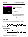
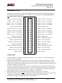
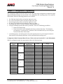
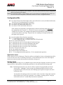
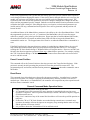
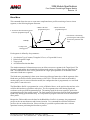
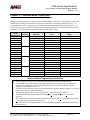
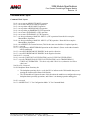
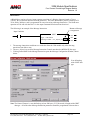
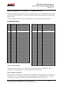
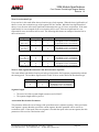
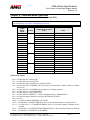
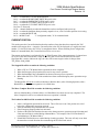
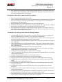
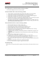
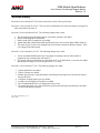
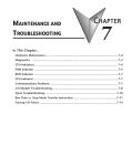
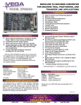
3204 Module Specifications
Four Channel ControlLogix Stepper Module
Revision 1.0
The 3204 module is a four-axis stepper controller that occupies one slot in a ControlLogix rack. This unit
receives profile data from the PLC and outputs Step and Direction signals or Clockwise/Counter
Clockwise pulses to a stepper driver. Inputs on the module allow homing and emergency stop operations.
The 3204 uses twenty 32 bit input words and twenty 32 bit output words. The four channels are totally
independent from each other and can be configured and programmed to perform different operations.
Because the 3204 module does not use a non-volatile memory, it must be configured at every power up.
Sample programs showing how to program the 3204 module are available from the following page of our
website.
http://www.amci.com/sampleprograms.asp
20 Gear Drive, Plymouth Industrial Park, Terryville, CT 06786
Tel: (860) 585-1254 Fax: (860)584-1973 E-mail: Sales @amci.com
page: 1
3204 Module Specifications
Four Channel ControlLogix Stepper Module
Revision 1.0
General Information
Important User Information
The products and application data described in this manual are useful in a wide variety of different
applications. Therefore, the user and others responsible for applying these products described herein are
responsible for determining the acceptability for each application. While efforts have been made to
provide accurate information within this manual, AMCI assumes no responsibility for the application or
the completeness of the information contained herein. Throughout this manual the following two notices
are used to highlight important points.
WARNINGS tell you when people may be hurt or equipment may be damaged if the procedure is not
followed properly.
CAUTIONS tell you when equipment may be damaged if the procedure is not followed properly. No
patent liability is assumed by AMCI, with respect to use of information, circuits, equipment, or software
described in this manual. The information contained within this manual is subject to change without
notice. UNDER NO CIRCUMSTANCES WILL ADVANCED MICRO CONTROLS, INC. BE
RESPONSIBLE OR LIABLE FOR ANY DAMAGES OR LOSSES, INCLUDING INDIRECT OR
CONSEQUENTIAL DAMAGES OR LOSSES, ARISING FROM THE USE OF ANY INFORMATION
CONTAINED WITHIN THIS MANUAL, OR THE USE OF ANY PRODUCTS OR SERVICES
REFERENCED HEREIN.
Standard Warranty
ADVANCED MICRO CONTROLS, INC. warrants that all equipment manufactured by it will be free
from defects, under normal use, in materials and workmanship for a period of [18] months. Within this
warranty period, AMCI shall, at its option, repair or replace, free of charge, any equipment covered by
this warranty which is returned, shipping charges prepaid, within one year from date of invoice, and
which upon examination proves to be defective in material or workmanship and not caused by accident,
misuse, neglect, alteration, improper installation or improper testing. The provisions of the “STANDARD
WARRANTY” are the sole obligations of AMCI and excludes all other warranties expressed or implied.
In no event shall AMCI be liable for incidental or consequential damages or for delay in performance of
this warranty.
Returns Policy
All equipment being returned to AMCI for repair or replacement, regardless of warranty status, must have
a Return Merchandise Authorization number issued by AMCI. Call (860) 585-1254 with the model and
serial numbers along with a description of the problem. A “RMA” number will be issued. Equipment
must be shipped to AMCI with transportation charges prepaid. Title and risk of loss or damage remains
with the customer until shipment is received by AMCI.
24 Hour Technical Support Number
Technical Support, in the form of documents, FAQs, and sample programs, is available from our website,
www.amci.com. 24 Hour technical support is also available on this product. For technical support, call
(860) 583-7271. Your call will be answered by the factory during regular business hours, Monday
through Friday, 8AM - 5PM EST. During non-business hours, an automated system will ask you to leave
a detailed message and the telephone number where you can be reached. The system will page an
engineer on call. Please have your product model number and a description of the problem ready before
you call.
20 Gear Drive, Plymouth Industrial Park, Terryville, CT 06786
Tel: (860) 585-1254 Fax: (860)584-1973 E-mail: Sales @amci.com
page: 2
3204 Module Specifications
Four Channel ControlLogix Stepper Module
Revision 1.0
Table of Contents
Installing the 3204 Module
Chapter 1
Installing the 3204 module
Configuring a ControlLogix system
Module Specifications
Discrete Input Specifications
Front Panel & LED Functions
Output Signals
Connector Pinout and Wiring Notes
Differential Output Wiring
4
4
4
5
5
6
6
7
8
Calculating Move Profiles
Chapter 2
9
Configuration Programming
Chapter 3
Configuration Bits
Input Active Level
Starting Speed
Invalid Configurations
Configuration Mode Input Data
11
12
12
12
13
13
Command Mode Operations
Chapter 4
Absolute & Relative Moves
Hold Move
Resume Move
Immediate Stop
Find Home +/(CW), Find Home -/(CCW)
Manual Move +/(CW), Manual
Move -/(CCW)
Preset Current Position
Reset Errors
Blend Move
Acceleration Types
14
14
15
15
15
16
18
19
19
20
21
Command Mode Output Data
Chapter 5
22
Command Words
22
Command Bits
23
Blend Move Programming (message instructions) 24
Command Mode Input Data
Chapter 6
Status Bits
Input Word Functions
Status & Error Bit Functions
Revision History
20 Gear Drive, Plymouth Industrial Park, Terryville, CT 06786
Tel: (860) 585-1254 Fax: (860)584-1973 E-mail: Sales @amci.com
27
27
28
28
31
page: 3
3204 Module Specifications
Four Channel ControlLogix Stepper Module
Revision 1.0
Chapter 1: Installing the 3204 module
The 3204 can be installed in any ControlLogix module slot as long as power supply requirements are met.
The 3204 module requires 560mA from the 5Vdc supply to operate.
1. Align the module’s circuit board with the top and bottom card guides in the rack.
2. Gently slide the module into the rack until the top and bottom latches secure the module in place.
To remove the module, depress the top and bottom latches and slide the module out of the rack.
Note The ControlLogix backplane is hot-swappable. That is, the 3204 module can be inserted and
removed under power.
Configuring the ControlLogix system for the 3204 module
1.
2.
3.
4.
Open RSLogix 5000 and the project in which you want to install the AMCI 3204 module.
Right click on I/O Configuration in the Project Tree.
Select New Module.
Select the following module type and description from the list that appears.
Type = 1756-MODULE
Description = Generic 1756 Module (This module will appear as an Unknown Device when viewed
from RSNetworx.)
Click on OK.
5. Enter the following module properties.
Name: Your Choice (must begin with a letter)
Description: Your Choice
Comm Format: Data-DINT (must be Data-DINT)
Slot: location of 3204 module
6. Enter the Connection Parameters from the following table. (The Listen Only columns will only be
used by any additional processors that are installed in the rack chassis.)
CONNECTION PARAMETERS
INPUT
OUTPUT
CONFIGURATION
Owner Controller
Assembly
Size in 32
Instance
bit words
100
20
194
20
242
0
Listen Only
Assembly
Size in 32
Instance
bit words
101
20
195
1
2
0
7. Click on Next >
8. Set the RPI (Rate Packet Interval) Time to the desired value. 5ms is the recommended value. The
minimum RPI is 0.5ms. However, below 3ms, the unit may occasionally lose communication with
the PLC.
9. Click on Finish >>
20 Gear Drive, Plymouth Industrial Park, Terryville, CT 06786
Tel: (860) 585-1254 Fax: (860)584-1973 E-mail: Sales @amci.com
page: 4
3204 Module Specifications
Four Channel ControlLogix Stepper Module
Revision 1.0
The 3204 module will now appear in the project tree and three new data tags will have been created,
Local:X.I.Data[Y], Local:X.O.Data[Y] and Local:X.C.Data[Y] where “X” is the slot number and “Y” is
the word number. The status and current position values are located in the Input tags. With the exception
of the programming of the blend move profile, which uses a message instruction; all commands are sent
to the 3204 module through the Output tags. The 3204 module does not use the Configuration tags.
Module Specifications
•
•
•
Backplane Current Draw: 560mA @5Vdc
Throughput Time: 500 µs
(Inputs must be on for 500µs to be scanned by the module)
Minimum recommended RPI time = 3ms
Stepper Outputs
•
•
•
5V differential (3.5V to 4Vdc peak typical)
Maximum Output Current: 20mA
Maximum Output Frequency: 1MHz
Discrete Inputs
•
•
•
•
•
•
Input Type: Sinking
Input Voltage Range:
On = 8 to 24Vdc
Off = 0 to 2Vdc
Input Current: 15mA @ 24Vdc
Response Time (On and Off): 5µs
The module interrogates the Discrete Inputs a maximum of every 500µs.
The Input Functions are described below
Emergency Stop
The Emergency Stop Input causes the current move operation to stop without any deceleration. The
pulse signal is simply stopped. If the channel was moving when this input was activated, the current
position will become invalid, and the Position Invalid Input Bit will be set. The channel will have to
be Preset or Homed again before an Absolute Move operation can be performed. However, it will be
possible to perform a Relative or a Manual Move after the Emergency Stop Input has been used.
Home Input
Reaching the Home Input during a homing operation will cause the 3204 module to reset the Current
Position to zero. The Home Input has no function unless a homing operation is being performed.
CW & CCW Limit Switch Inputs
During most move operations, the CW and CCW Limit Switches act as an Emergency Stop input.
There are two exceptions. The first is during a homing operation, where the direction of motion will
be reversed and the module will start looking for the Home Input in the opposite direction. The
second is if the opposite end limit switch is reached during a Manual Move operation. For example if
the CW limit switch is reached during a CCW Manual Move. In this case, the module will ignore the
End Limit Switch input. Each channel of the 3204 module must be configured with at least one of
these Limit Switch Inputs.
20 Gear Drive, Plymouth Industrial Park, Terryville, CT 06786
Tel: (860) 585-1254 Fax: (860)584-1973 E-mail: Sales @amci.com
page: 5
3204 Module Specifications
Four Channel ControlLogix Stepper Module
Revision 1.0
Front Panel
LED Function
Status LED (Listed by priority)
Solid Red: Module failed power up diagnostics
Blinking Red: Configuration Error, Command Error, Input
Error, Home Invalid Error, or an Invalid Profile
Error. Set when error detected on any channel.
Blinking Green: Motion on any channel
Solid Green: Module OK, no motion in progress, at least one
channel configured
Off: All channels disabled
OK LED
Solid Red: Module Fault
Blinking Red: Communication between module and PLC
interrupted
Blinking Green: PLC is in Program Mode or one way
communication, module only sends data to the
PLC, or slot is not correctly configured for the
module
Solid Green: Module Owned, two way communication
Output Signals
The 3204 module can be programmed to output either Step and Direction signals or CW / CCW steps.
There is no advantage to either type; you must simply configure each channel of the 3204 module to
match the input type of your driver. The two signals types are illustrated below.
Step and Direction Output
Step Output
Direction Output
CCW Motion or Decreasing Counts
CW Motion or Increasing Counts
CW and CCW Step Outputs
Increasing Counts
CW Output
Decreasing Counts
CCW Output
20 Gear Drive, Plymouth Industrial Park, Terryville, CT 06786
Tel: (860) 585-1254 Fax: (860)584-1973 E-mail: Sales @amci.com
page: 6
3204 Module Specifications
Four Channel ControlLogix Stepper Module
Revision 1.0
Connector Pin Out:
The input connector consists of a Removable Terminal Block with the Rockwell Automation Part Numbers
1756-TBCH (36 position cage clamp) or 1756-TBS6H (36 position spring clamp). The terminal block is
not supplied with the 3204 module.
Channel 1 +Step or +CW Output
2
1
Channel 3 +Step or +CW Output
Channel 1 –Step or –CW Output
4
3
Channel 3 –Step or –CW Output
Channel 1 +Dir. or +CCW Output
6
5
Channel 3 +Dir. or +CCW Output
Channel 1 –Dir. or –CCW Output
8
7
Channel 3 –Dir. or –CCW Output
Chassis Ground (shields)
10
9
Chassis Ground (shields)
Channel 2 +Step or +CW Output
12
11
Channel 4 +Step or +CW Output
Channel 2 –Step or –CW Output
14
13
Channel 4 –Step or –CW Output
Channel 2 +Dir. or +CCW Output
16
15
Channel 4 +Dir. or +CCW Output
Channel 2 –Dir. or –CCW Output
18
17
Channel 4 –Dir. or –CCW Output
Channel 1 Home Input
20
19
Channel 3 Home Input
Channel 1 Emergency Stop Input
22
21
Channel 3 Emergency Stop Input
Channel 1 CW Limit Switch
24
23
Channel 3 CW Limit Switch
Channel 1 CCW Limit Switch
26
25
Channel 3 CCW Limit Switch
Channel 2 Home Input
28
27
Channel 4 Home Input
Channel 2 Emergency Stop Input
30
29
Channel 4 Emergency Stop Input
Channel 2 CW Limit Switch
32
31
Channel 4 CW Limit Switch
Channel 2 CCW Limit Switch
34
33
Channel 4 CCW Limit Switch
Module Common
36
35
Module Common
Wiring Notes
•
•
•
•
•
•
•
The 3204 module uses a DS26LS31 differential line driver in series with a 10Ω resistor for the stepper (+/step and +/- direction) outputs.
Stepper signals are generally low voltage, low power signals. If you are using A-B guidelines for cabling
installation, treat the cable as a Category 2 cable. It can be installed in conduit along with other low power
cabling such as communication cables and low power ac/dc I/O lines. It cannot be installed in conduit with ac
power lines or high power ac/dc I/O lines.
To reduce or eliminate the influence of electrical noise on the system, the step and direction cable shields
must be connected to chassis ground terminals 9 or 10. Also, the shields must be connected to only one end
of the cable run and treated as conductors at any junctions. Do not ground the shields at the junction box.
If the signal cable must cross power feed lines, it should do so at right angles.
Route the cable at least five feet from high voltage enclosures, or sources of “rf” radiation.
The Module Common terminals must be connected to the COM of the supply that powers the discrete inputs.
A Stepper Driver with Single Ended Step and Direction inputs can also be referenced here.
The Chassis Ground pin is connected to the PLC’s chassis ground.
20 Gear Drive, Plymouth Industrial Park, Terryville, CT 06786
Tel: (860) 585-1254 Fax: (860)584-1973 E-mail: Sales @amci.com
page: 7
3204 Module Specifications
Four Channel ControlLogix Stepper Module
Revision 1.0
Differential Wiring Diagram
The pulse and direction cable shields must be
connected to chassis ground input pins 9 or 10
20 Gear Drive, Plymouth Industrial Park, Terryville, CT 06786
Tel: (860) 585-1254 Fax: (860)584-1973 E-mail: Sales @amci.com
page: 8
3204 Module Specifications
Four Channel ControlLogix Stepper Module
Revision 1.0
Chapter 2: Calculating Move Profiles
Before starting a move operation, the 3204 module completely calculates each portion of the move
profile. That is, it calculates how many steps of the move profile will be required for acceleration and
how many steps will be required for deceleration. Depending on the data used to define the move profile,
this can result in two types of velocity profiles, either a Trapezoidal Profile or a Triangular Profile.
A Trapezoidal Profile jumps from rest to the Starting Speed, accelerates to the Programmed Velocity at
the commanded acceleration rate, continues at the Programmed Velocity to a predetermined point, and
then decelerates to the target position at the commanded deceleration rate to the starting speed and stops.
Velocity
Trapezoidal Profile
Starting
Speed
Time
However, if the length of a commanded move is not long enough to attain the programmed velocity
before the deceleration point is reached, a Triangular Velocity profile will be generated.
Velocity
Triangular Profile
Starting
Speed
Time
Regardless of the type of Velocity Profile that is being run, the following equations can be used to
determine both the time to accelerate and the number of steps needed to accelerate. These formulas can
also be used to calculate the time and distance to decelerate.
Ta = (Vs – Vo)/a
Da = Ta * (Vo + Vs)/2
Vo = Starting Speed (steps/second)
Vs = Programmed Speed (steps/second)
Ta = Time to accelerate (seconds)
Da = Distance to accelerate (steps)
a = Acceleration rate (steps/second/second)
Velocity
Vs
Vo
20 Gear Drive, Plymouth Industrial Park, Terryville, CT 06786
Tel: (860) 585-1254 Fax: (860)584-1973 E-mail: Sales @amci.com
Time
page: 9
3204 Module Specifications
Four Channel ControlLogix Stepper Module
Revision 1.0
Calculation Notes
1. The acceleration and deceleration values sent to the 3204 module as part of the move profile have
units of steps/second/second.
2. The acceleration and deceleration values have a minimum value of 1,000 steps/second/second
and a maximum of 2,000,000 steps/second/second.
3. If the number of steps to accelerate plus the number of steps to decelerate is greater than the
number of steps programmed in the target position registers, than the 3204 module will run a
Triangular Velocity Profile.
4. If the number of steps to accelerate plus the number of steps to decelerate is less than the number
of steps programmed in the target position, than the 3204 module will run a Trapezoidal Velocity
Profile.
Velocity
Vs
Starting
Speed
Da
Ds
Dd
Tt
Ds = (Total Number of Steps) – (Da + Dd)
Tt = Ta + Td + Ds/Vs
Da = Distance to Accelerate (steps)
Ds = Distance at the programmed speed (steps)
Dd = Distance to decelerate (steps)
Vs = Programmed Speed (steps/sec)
Tt = Total Profile Time (seconds)
Starting Speed
The starting speed has a range of 1 to 1,000,000 steps/sec and is the pulse frequency at which every move
begins and ends. That is, the first and last steps of the move profile will be at the starting speed. Some
portions of the homing operations are also performed at the starting speed.
The Starting Speed can be any value less than or equal to the programmed speed of the slowest move.
Although it is not necessary, the smoothest transition from rest to the programmed speed will be achieved
with a Starting Speed equal to the square root of the acceleration value.
You may have the starting speed set to too small a value if you have a larger than expected delay between
two of your move operations. For example, a starting speed of 1 step per second will result in a 1 second
delay between move operations.
20 Gear Drive, Plymouth Industrial Park, Terryville, CT 06786
Tel: (860) 585-1254 Fax: (860)584-1973 E-mail: Sales @amci.com
page: 10
3204 Module Specifications
Four Channel ControlLogix Stepper Module
Revision 1.0
Chapter 3: Configuration Programming
The Configuration Mode provides the ability to select the proper setup configuration to match the stepper
application without having to set any switches. The configuration file, consisting of two 32 bit words on
each channel, allows the following parameters to be defined.
1.
2.
3.
4.
5.
6.
If a CW Limit Switch will be used and its input active state
If a CCW Limit Switch will be used and its input active state
If an Emergency Stop will be used and its input active state.
If a Home Limit Switch will be used and its input active state.
The output type, either CW and CCW Steps or Step and Direction.
The type of homing operation that will be performed. There are two Homing possibilities.
•
•
Home Limit Switch Only
Home Limit Switch with a backplane bit acting as a Home Proximity. The backplane
proximity bit is a set by the PLC to indicate to the 3204 module that you are nearing the
location of the Home Limit Switch
7. The Starting Speed. The starting speed is the pulse frequency that every move begins and ends at.
Some portions of the homing operations are also performed at the starting speed.
Configuration Mode Consumed Data (Twenty 32 bit words sent from the PLC to the 3204 module)
While in configuration mode, the output registers have the following format.
32 bit output
Word
0
1
2
3
4
5
6
7
8
9
10
11
12
13
14
15
16
17
18
19
Channel
1
2
3
4
Configuration
Output Data
Configuration Bits
Starting Speed
0
0
0
Configuration Bits
Starting Speed
0
0
0
Configuration Bits
Starting Speed
0
0
0
Configuration Bits
Starting Speed
0
0
0
Units
Steps / Second
Steps / Second
Steps / Second
Steps / Second
20 Gear Drive, Plymouth Industrial Park, Terryville, CT 06786
Tel: (860) 585-1254 Fax: (860)584-1973 E-mail: Sales @amci.com
Range
See description below
1 to 1,000,000
Must be zero
Must be zero
Must be zero
See description below
1 to 1,000,000
Must be zero
Must be zero
Must be zero
See description below
1 to 1,000,000
Must be zero
Must be zero
Must be zero
See description below
1 to 1,000,000
Must be zero
Must be zero
Must be zero
page: 11
3204 Module Specifications
Four Channel ControlLogix Stepper Module
Revision 1.0
Note 1: At power up, all of channels will be disabled. They will remain disabled as long as configuration
data is not written to the module.
Note 2: If Configuration Mode is entered while a move is occurring, the Command Error bit will be set,
the move will run to completion, and then the module will enter Configuration Mode.
Configuration Bits
Bit 0: set when a Home Limit Switch Input will be used (If this bit is not set, the Home Invalid status
bit will be set if a homing operation is initiated.)
Bit 1: set when the Emergency Stop Input will be used
Bit 2: set when a CW Limit Switch will be used
Bit 3: set when a CCW Limit Switch will be used
Even if they are not required by your application, at least one end limit switch must exist in
the configuration data. Set bits 2, 3, 18, and 19 if you are not using either of the end limit
switches in your system. This configures the channel for both end limit switch inputs and
sets the active state to active high. Simply do not wire anything to the input terminals and
the inputs will be ignored.
Bit 4: set for backplane Home Proximity operations
Bit 5: “1” when output pulse type is step and direction
“0” when output pulse type is CW pulse train and CCW pulse train
Bits 6 to15: reserved for future use
Bit 16: determines the active level of the Home Limit Switch input
Bit 17: determines the active level of the Emergency Stop input
Bit 18: determines the active level of the CW Limit Switch
Bit 19: determines the active level of the CCW Limit Switch
Bits 20 to 27: Reserved for future use
Bit 28: Set to disable the channel
Bits 29 and 30: Reserved for future use
Bit 31: “1” for configuration mode operations, “0” for command mode operations
Input Active Level
Defines the active level of the inputs. These bits will be set for high level active or Normally Open (NO),
or reset for low level active or Normally Closed (NC). Please note that the active level of the inputs is
taken into account only when the input has been defined as being used.
Starting Speed
The starting speed has a range of 1 to 1,000,000 steps/sec and is the pulse frequency at which every move
begins and ends. Some portions of the homing operations are also performed at the starting speed.
Note: The Starting Speed can be any value less than or equal to the programmed speed of the
slowest move. Although it is not necessary, the smoothest transition from rest to the
programmed speed will be achieved with a Starting Speed equal to the square root of the
acceleration value.
You may have the starting speed set to too small a value if you have a larger than expected
delay between two of your move operations. For example, a starting speed of 1 step per
second will result in a 1 second delay between move operations.
20 Gear Drive, Plymouth Industrial Park, Terryville, CT 06786
Tel: (860) 585-1254 Fax: (860)584-1973 E-mail: Sales @amci.com
page: 12
3204 Module Specifications
Four Channel ControlLogix Stepper Module
Revision 1.0
Invalid Configurations
Invalid Configurations
The 3204 module will not accept all possible configurations. The following is a list of the invalid
configurations:
1.
2.
3.
4.
5.
A configuration without at least one End Limit Switch, either CW or CCW.
Using the Backplane Home Proximity bit without the Home Limit Switch.
A starting speed outside the range of 1 < starting speed < 1,000,000.
Setting any of the unused bits in the configuration word.
Setting any of the unused words to a value other than zero.
The 3204 has to be configured before starting any operations. When the Configuration Mode bit is set in
the output registers, the stepper controller enters Configuration Mode. When in this mode, the stepper
controller will stop its operations and set the Configuration Mode status bit in the input registers. It then
waits for the configuration file to be transferred. If there is no current Configuration File present or if the
transferred Configuration File is not valid, the Configuration Error Input bit will be set. If the transferred
configuration file is accepted, and if it is different from the current configuration, the configuration data
will be mirrored in the input registers.
Configuration Mode Input Data
While in configuration mode, the input registers will mirror the configuration data that was sent to the
3204 module in the output registers. The exceptions are the Module OK bit, status bit 30, the Channel
Disabled bit, status bit 28, and the Configuration Error bit, status bit 13.
32 bit Input
Word
0
1
2
3
4
5
6
7
8
9
10
11
12
13
14
15
16
17
18
19
Channel
1
2
3
4
Configuration
Input Data
Mirror of Configuration Bits
Mirror of Starting Speed
0
Bits 16 to 31 = Major Revision, Bits 0 to 15 = Minor Revision
0
Mirror of Configuration Bits
Mirror of Starting Speed
0
Bits 16 to 31 = Major Revision, Bits 0 to 15 = Minor Revision
0
Mirror of Configuration Bits
Mirror of Starting Speed
0
Bits 16 to 31 = Major Revision, Bits 0 to 15 = Minor Revision
0
Mirror of Configuration Bits
Mirror of Starting Speed
0
Bits 16 to 31 = Major Revision, Bits 0 to 15 = Minor Revision
0
20 Gear Drive, Plymouth Industrial Park, Terryville, CT 06786
Tel: (860) 585-1254 Fax: (860)584-1973 E-mail: Sales @amci.com
page: 13
3204 Module Specifications
Four Channel ControlLogix Stepper Module
Revision 1.0
Chapter 4: Command Mode Operations
The following is a description of the various commands that the module accepts and the operations that it
will perform while in Command Mode. When switching from Configuration Mode to Command Mode,
the position will be invalid and the Current Position will be zero.
Absolute/Relative Move
The current position must be valid in order to perform an ABSOLUTE MOVE. A HOME or PRESET
operation will have to be performed before the position becomes valid. The distance moved, that is the
number of steps issued by the 3204, is equal to the difference between the Target Position and the Current
Position. For example, if the Current Position is 5000, and the Target Position is 7500, than the unit will
output 2500 steps. After the Absolute Move has been completed, the Current Position will be 7500. The
direction of motion of an Absolute Move is determined by the relationship between the Current Position
and Target Position. If the Target Position > Current Position, than CW motion will occur. If the Target
Position < Current Position, than CCW motion will occur.
The current position does not have to be valid to perform a RELATIVE MOVE. The Target Position
defines the distance, in number of steps, to travel relative to the Current Position. For example, if the
Current Position is 5000 and the Target Position is 7500, than the unit will output 7500 steps. After the
Relative Move has been completed, the Current Position will be 12,500. The direction of motion of a
Relative Move is selected by the sign of the Target Position. A positive Target Position will generate a
CW move while a negative Target Position will generate a CCW move.
The ABSOLUTE or RELATIVE MOVE operations can produce two different velocity profiles.
Normally the move operations start at the Starting Speed, accelerate to the Programmed speed at the
defined acceleration rate, continue at the Programmed speed until it is time to decelerate back to the
Starting Speed, and Stop. This generates a trapezoidal velocity profile.
However, if the move operation does not reach the Programmed speed by the time the deceleration is to
begin, the move is decelerated to the Starting Speed and Stopped. In this way a triangular velocity profile
is generated.
If the move operation runs to completion without error, the MOVE COMPLETE FLAG is set. If an error
does occur, the MOVE COMPLETE FLAG will not be set, and an error flag will be set. The Move
Complete status bit will be reset at the beginning of the next move operation.
It is possible to hold both Absolute or Relative moves either by issuing a backplane Hold Command.
20 Gear Drive, Plymouth Industrial Park, Terryville, CT 06786
Tel: (860) 585-1254 Fax: (860)584-1973 E-mail: Sales @amci.com
page: 14
3204 Module Specifications
Four Channel ControlLogix Stepper Module
Revision 1.0
Hold Move
The HOLD MOVE command causes the move operation to decelerate at the programmed deceleration
rate to the Starting Speed and stop. When this operation is successfully completed, the module will set
the Hold State Input status bit. You have two options while the 3204 module is in a Hold state. Either
the Resume Move command can be issued, with our without changing the velocity, acceleration, or
deceleration parameters, or an entirely new move profile can be sent to the 3204 module.
Note 1: Only the Hold Move bit must be set in the Command Word. A Command Error will be
generated, and the Hold Command ignored, if any other command bits set at the same time.
Note 2: Because the module is already decelerating, it will ignore a Hold Move command issued during
the deceleration part of the profile.
Note 3: A Blend Move cannot be held. If a Hold Move command is issued during a Blend Move
operation, the module will generate a command error, motion will continue until the blend move
is complete, when the Command Error bit will be reset.
Note 4: A Hold Move command issued during a manual move generates a command error and will cause
a controlled stop. The position will not become invalid.
Note 5: Issuing a Hold Command during a Homing operation will cause a command error to be
immediately generated, but the home operation will run to completion.
Resume Move
The RESUME MOVE command resumes a previously held Absolute or Relative Move. If the Resume
Move command is the first one issued after a Hold Move operation, and no errors have occurred, motion
will start from the point where it was stopped. The Hold State status bit will also be reset. If Triangular S
Curve or Trapezoidal S Curve acceleration is required, the appropriate acceleration type bit(s) must be set
at the same time the Resume Move bit is set. When the move operation has been successfully completed,
the Move Complete Flag will be set.
A move operation can be held and resumed many times until one of the following has occurred:
•
•
•
The move reaches its programmed target position
An error condition has occurred
Some other command is issued
Immediate Stop
The Immediate Stop command causes the current move operation to stop without any deceleration. The
step signal is simply stopped. If the channel was moving when this command was issued, the current
position will become invalid, and the Position Invalid Input Bit will be set. The channel will have to be
Preset or Homed again before an Absolute Move operation can be performed. However, it will be
possible to perform a Relative Move or a Manual Move after an Immediate Stop command has been
issued. There will be no changes to the Status Bits if the Immediate Stop command is issued when
motion was not occurring.
20 Gear Drive, Plymouth Industrial Park, Terryville, CT 06786
Tel: (860) 585-1254 Fax: (860)584-1973 E-mail: Sales @amci.com
page: 15
3204 Module Specifications
Four Channel ControlLogix Stepper Module
Revision 1.0
Find Home +/(CW), Find Home -/(CCW)
Find Home +/(CW), Find Home -/(CCW)
There are two homing options available. They are,
1. Home Limit Switch Only
2. Home Limit Switch with a backplane Home Proximity bit.
When the homing operation is complete, the 3204 will set the At Home input bit, and then reset the
current position to zero.
The Find Home commands require that both the Home Input and at least one End Limit Switch, either
CW or CCW, be configured. The 3204 will not accept a Find Home command if the Home Input has not
been configured. It will also not accept a Find Home +/(CW) command when there is no CW Limit
Switch configured or a Find Home -/(CCW) command when there is no CCW Limit Switch configured.
If any of these operations are attempted, the COMMAND ERROR Input bit will be set.
S-Curve acceleration profiles are not allowed during a homing operation. Initiating a home operation
with S curve accelerations will cause a Command Error to be generated.
If, during a Home operation, either of the End Limit Switch endpoints are reached, the module will stop
outputting pulses (essentially an emergency stop), wait for two seconds, reverse direction, and start
searching for the appropriate homing signal again. It is important not to have the velocity set too high
during a homing operation. The sudden stop and change in direction at high speeds may cause the motor
to lock up.
The following diagrams illustrate the different homing options.
Home Limit Switch Only
2. Runs at the
programmed speed
1. Accelerates to
programmed speed
6. Decelerates when the Home
Limit Switch goes On then
Off. Waits 2 seconds
3. Detects the Home Limit
Switch
4. Decelerates to stop
and waits 2 seconds.
5. Accelerates to the programmed
speed opposite to the requested
direction
7. Returns to the Home Limit
Switch at the starting speed
20 Gear Drive, Plymouth Industrial Park, Terryville, CT 06786
Tel: (860) 585-1254 Fax: (860)584-1973 E-mail: Sales @amci.com
page: 16
3204 Module Specifications
Four Channel ControlLogix Stepper Module
Revision 1.0
Backplane Home Proximity Bit with Home Limit Switch
2. Runs at the
programmed speed
3. Detects backplane proximity bit and
decelerates to the starting speed.
4. Runs at the starting speed.
1. Accelerates to
programmed speed
5. Detects Home Limit
Switch and stops.
Reaching an End Limit Switch During a Homing Operation
1. Runs at the Programmed Speed
2. Reaches the end Limit Switch,
stops without deceleration, and
waits for two seconds
4. Waits for the Home
Input to turn On then
Off.
3. Turns at the programmed speed opposite
to the requested direction
5. Returns at the starting speed to where the Home
Input was detected. Continues to the Home Limit
Switch if applicable.
Note: The Home Input shown above can be either the Home Limit Switch or the Backplane Proximity bit.
Home Limit Switch Active when the Home Command is issued
1. Home Limit Switch Active
(gray used to indicate width
of home limit switch)
2. Turns at the programmed speed in the direction
opposite to the requested homing operation until the
home limit switch turns off
3: Decelerates when the Home
Limit Switch turns off
4. Returns at the starting speed to where the
home limit switch was detected
20 Gear Drive, Plymouth Industrial Park, Terryville, CT 06786
Tel: (860) 585-1254 Fax: (860)584-1973 E-mail: Sales @amci.com
page: 17
3204 Module Specifications
Four Channel ControlLogix Stepper Module
Revision 1.0
End Limit Switch Active when the Home Command is issued
3. Home input is detected
going on and off
2. Motor turns at the programmed speed in the
direction opposite of the requested homing operation
4. Motor decelerates
and stops
1. End Limit Switch active when home
command is issued
5. Runs at the starting speed until the home
input again turns on.
Note 1: The Home Input shown above can be either the Home Limit Switch or the Backplane Proximity
bit.
Note 2: The above diagram is only true if the active End Limit Switch is the same as the issued home
command, for example if the CW Limit Switch is active and a CW home command is issued. If
the CW Limit Switch is active and a CCW home command is issued, than the unit will home
normally, as if the end limit switch was not active.
Manual Move +/(CW), Manual Move -/(CCW)
This command performs the Manual Move operation at the programmed speed in the specified direction.
Motion will occur as long as the command bit remains set. The Target Position register must be zero
during all Manual Move operations.
If the programmed speed is less than or equal to the starting speed, the starting speed is not used and the
acceleration and deceleration parameters are ignored. The motor will “jump” to and run at the
programmed speed without any acceleration.
The speed cannot be changed when the module is running in this “constant speed mode.” If it is, a
Command Error will be generated and the motion will be stopped.
If the programmed speed is greater than the starting speed, the axis begins the move at the starting speed,
accelerates until the programmed speed is reached, and continues to move at the programmed speed until
one of the following occurs:
-The Manual Move command bit is turned off
-The Immediate Stop output bit is set
-The Emergency Stop Input is activated
-The End Limit Switch in the same direction as the motion is reached
-The Programmed speed Changes
If the Manual Move command bit is turned off, the axis will decelerate at the programmed rate to the
starting speed and stop, retaining a valid position. If the Immediate Stop Output bit or the Emergency
Stop Input is used, the axis will stop without deceleration and the position will become invalid.
20 Gear Drive, Plymouth Industrial Park, Terryville, CT 06786
Tel: (860) 585-1254 Fax: (860)584-1973 E-mail: Sales @amci.com
page: 18
3204 Module Specifications
Four Channel ControlLogix Stepper Module
Revision 1.0
If the initial programmed speed is greater than the starting speed, the speed of a Manual Move operation
can be changed without stopping the motion. If the velocity data is changed while the axis is moving, the
module will accelerate or decelerate to the new speed, which can be less than the starting speed. The
acceleration and or the deceleration parameters can also be changed, although these changes do not take
affect until the programmed speed is changed. Both the acceleration and deceleration parameters must be
valid when the speed is changed. If the changed velocity, acceleration, or deceleration parameters are
invalid, motion will stop, command and invalid profile errors will be generated, and the position will
become invalid.
An additional feature of the Manual Move parameter is the ability to do a One Shot Manual Move. With
the programmed speed set to zero, a 0 → 1 transition of the Manual Move bit will cause the stepper
controller to output 1 pulse in the specified direction. Please note that in One Shot Manual Move mode,
the motion Direction bit will remain on and the Status LED will flash as long as the Manual Move
command bit remains set. The Stopped status bit will not be set when the Manual Move command bit is
reset.
If the End Limit Switch in the same direction as motion is reached during a Manual Move, the axis will
stop without deceleration and the input error and position invalid input bits will be set. For example,
reaching the CW Limit Switch during a CW Manual Move will stop the motion. However, an End Limit
Switch in the direction opposite to motion will not stop a Manual Move operation. For example, reaching
the CCW Limit Switch during a CW Manual Move. This feature allows the module to be moved off of
an active end limit switch.
Preset Current Position
This command will set the Current Position to the value present in the Target Position Registers. If the
position is currently invalid, presetting the position will cause the position to become valid. The
programmed speed, acceleration, and deceleration parameters must be zero when this command is sent to
the module.
Reset Errors
This command clears all nonfatal errors detected by the stepper controller. A nonfatal error is one that
can be recovered from. For example, requesting an Absolute Move when the position is not valid is a
nonfatal error. When there is a Command Error, the controller will not perform any other operations until
the Reset Errors command is issued.
General Command Mode Operation Notes
1. Only one command bit can be set at any one time.
2. A Command Error will be generated if a move operation is started before the previous move
operation is completed. A move operation should only be started if the Move Complete, Stopped,
or Hold status bits are set.
3. Only a 0 to 1 transition of any of the control bits listed above will cause the specified operation to
take place.
4. If either the CW or CCW Limit Switches are reached during a normal move or manual move
operation, the module will treat the input as an emergency stop, meaning that the motor will stop
and the position will become invalid.
5. It is possible to home the 3204 module off of an end limit switch.
20 Gear Drive, Plymouth Industrial Park, Terryville, CT 06786
Tel: (860) 585-1254 Fax: (860)584-1973 E-mail: Sales @amci.com
page: 19
3204 Module Specifications
Four Channel ControlLogix Stepper Module
Revision 1.0
Blend Move
This command allows the user to create more complicated move profiles consisting of two to sixteen
segments, as the following diagram illustrates.
2. Accelerates from the starting speed
to the first programmed speed
3. Runs at the first
programmed speed
4. Runs at the final
programmed speed
5. Decelerates to the starting
speed using the final segment
deceleration parameter and
stops
Velocity
1. Jumps to the
starting speed
Position
Each segment is defined by four parameters:
1.
2.
3.
4.
Acceleration Type (Constant, Triangular S Curve, or Trapezoidal S curve)
Relative Segment Length
Target speed
Acceleration/Deceleration Rate
The minimum amount of information necessary to define a new move segment is the Target Speed. The
Segment Length and the Acceleration/Deceleration rate do not have to change from one segment to the
next. An Invalid Profile Error will be generated if the Target Speed parameter is not different in two
consecutive blend move segments.
The blend move programming is done at one time using a Message Instruction, with the segments of the
blend move profile stored in the internal memory of the 3204. This data will remain in the module’s
memory until power is removed from the module, the configuration data is programmed, or a new blend
move profile is sent to the unit.
The Blend Move Profile is programmed as a series of Relative Moves, so the position does not have to be
valid for the blend move operation to take place. The first segment starts at the Starting Speed and
accelerates to the specified Programmed speed. The starting speed for the next segment is equal to the
programmed speed of the current segment. The final segment will decelerate from the final programmed
speed to the starting speed and then stop. It is not possible to program a direction reversal in the blend
move profile.
Because the 3204 module stores the data for the Blend Move Profile in its memory, the programmed
profile can be run more than once and from any location. Two command bits allow the blend move
profile to be run in either direction. Please note that it is possible to perform other move or home
operations between performing the blend move profiles.
20 Gear Drive, Plymouth Industrial Park, Terryville, CT 06786
Tel: (860) 585-1254 Fax: (860)584-1973 E-mail: Sales @amci.com
page: 20
3204 Module Specifications
Four Channel ControlLogix Stepper Module
Revision 1.0
Acceleration Types
With the exception of homing operations, all of the move operations defined above allow the type of
acceleration to be selected. The three options are described below.
Constant Acceleration: The module accelerates at a constant rate until the programmed speed is reached.
This is the only option for homing operations.
Velocity
Acceleration
T
T
Time
Time
Triangular S Curve Acceleration: The module accelerates slowly at the beginning of the acceleration,
faster at the middle of the acceleration, and again slowly at the end of
the acceleration. The acceleration rate is never constant.
Acceleration
Velocity
T
T/2
Time
Time
T/2
Trapezoidal S Curve Acceleration: The module accelerates slowly at the beginning of the acceleration, at
a constant rate at the middle of the acceleration, and again slowly at
the end of the acceleration.
Velocity
Acceleration
T
Time
T/4
T/2
T/4
Time
Notes:
1. The defined acceleration type is also applied to the deceleration.
2. Constant acceleration has the shortest acceleration time and Triangular S Curve has the longest
acceleration time.
3. The constant portion of the Trapezoidal S Curve Acceleration is 50% of the total acceleration time.
20 Gear Drive, Plymouth Industrial Park, Terryville, CT 06786
Tel: (860) 585-1254 Fax: (860)584-1973 E-mail: Sales @amci.com
page: 21
3204 Module Specifications
Four Channel ControlLogix Stepper Module
Revision 1.0
Chapter 5: Command Mode Output Data
(Twenty 32 bit words sent from the PLC to the 3204 module)
All stepper motor operations are performed in Command Mode. This mode is entered, after a successful
configuration file has been transferred to the stepper controller, by resetting the Mode Flag bit 31. In
Command Mode, the PLC program can issue commands and activate different operations or moves. A
move profile typically consists of a Target Position, Programmed Speed, Acceleration, and Deceleration
parameters. The following table shows the function of the output words.
32 bit
Output Word
0
1
2
3
4
5
6
7
8
9
10
11
12
13
14
15
16
17
18
19
Channel
1
2
3
4
Function
Command
Target Position
Programmed Speed
Acceleration
Deceleration
Command
Target Position
Programmed Speed
Acceleration
Deceleration
Command
Target Position
Programmed Speed
Acceleration
Deceleration
Command
Target Position
Programmed Speed
Acceleration
Deceleration
Units
Steps
Steps/Second
Steps/Second/Second
Steps/Second/Second
Steps
Steps/Second
Steps/Second/Second
Steps/Second/Second
Steps
Steps/Second
Steps/Second/Second
Steps/Second/Second
Steps
Steps/Second
Steps/Second/Second
Steps/Second/Second
Range
See description below
-8,388,608 to 8,388,607
Starting Speed to 1,000,000
1,000 to 2,000,000
1,000 to 2,000,000
See description below
-8,388,608 to 8,388,607
Starting Speed to 1,000,000
1,000 to 2,000,000
1,000 to 2,000,000
See description below
-8,388,608 to 8,388,607
Starting Speed to 1,000,000
1,000 to 2,000,000
1,000 to 2,000,000
See description below
-8,388,608 to 8,388,607
Starting Speed to 1,000,000
1,000 to 2,000,000
1,000 to 2,000,000
Command Mode Programming Information
1. Only a single bit can be set at any one time in the Most Significant Command Word.
2. A Command Error will be generated if a move operation is started before the previous move
operation has completed. A move operation should only be started if the Move Complete,
Stopped, or Hold status bits are set.
3. A negative Target Position value will be programmed as a negative decimal number. If viewed in
binary, this will be 2s compliment format.
4. The Position parameter has a range of -8,388,608 < Target Position < 8,388,607.
5. The Programmed Speed has a range of Starting Speed < Programmed Speed < 1,000,000
steps/sec.
6. The acceleration and deceleration parameters have a range of 1,000 < acceleration / deceleration
< 2,000,000 and is measured in steps/sec/sec.
7. Switching the PLC to Program Mode will cause any move operation to stop and the position to
become invalid.
20 Gear Drive, Plymouth Industrial Park, Terryville, CT 06786
Tel: (860) 585-1254 Fax: (860)584-1973 E-mail: Sales @amci.com
page: 22
3204 Module Specifications
Four Channel ControlLogix Stepper Module
Revision 1.0
Command Word Layout
Command Word Layout
bit 0 = set to start an ABSOLUTE MOVE operation
bit 1 = set to start a RELATIVE MOVE operation
bit 2 = set to perform a HOLD MOVE operation
bit 3 = set to perform a RESUME MOVE operation
bit 4 = set to perform an IMMEDIATE STOP operation
bit 5 = set to start a FIND HOME +/(CW) operation
bit 6 = set to start a FIND HOME -/(CCW) operation
bit 7 = set when performing a MANUAL MOVE +/(CW) operation. Reset this bit to stop the
Manual Move Operation.
bit 8 = set when performing a MANUAL MOVE -/(CCW) operation. Reset this bit to stop the
Manual Move Operation.
bit 9 = set to PRESET the Current Position (This bit does not reset the Move Complete input bit)
bit 10 = reserved
bit 11 = set to perform a RESET ERRORS operation on this channel. (Errors on the other channels
will be unaffected)
bit 12 = set to RUN BLEND MOVE PROFILE in the positive direction
bit 13 = set to RUN BLEND MOVE PROFILE in the negative direction
bits 14 & 15 = reserved
bit 16 = reset for CONSTANT ACCELERATION, set for S CURVE ACCELERATION
bit 17 = reset for TRIANGULAR S CURVE ACCELERATION, set for TRAPOZOIDAL S
CURVE ACCELERATION. This bit is only valid if bit 16 is set, otherwise it will be a
“don’t care.”
bits 18 to 28 = Reserved
bit 29: Backplane Home Proximity bit.
•
•
The backplane proximity bit is a set by the PLC to indicate to the 3204 module that you are
nearing the location of the Home Limit Switch.
The 3204 module will ignore the state of this bit unless the module was configured to accept
backplane home proximity operations, and if there is no homing operation taking place
bit 30 = reserved
bit 31 = MODE FLAG: "1" for Configuration Mode "0" for Command Mode
20 Gear Drive, Plymouth Industrial Park, Terryville, CT 06786
Tel: (860) 585-1254 Fax: (860)584-1973 E-mail: Sales @amci.com
page: 23
3204 Module Specifications
Four Channel ControlLogix Stepper Module
Revision 1.0
Blend Moves
A Blend Move consists of up to sixteen segments consisting of a Relative Segment Length, a Target
Velocity, the Acceleration and Deceleration parameters. The entire Blend Move profile is made up of 52
32 bit words, 208 bytes, and is programmed all at one time using a Message Instruction. The blend move
operation will be run each time bit 11 in the output Command word transitions from 0 to 1.
The following is an example of the Message Instruction
Button to Message
Configuration
Input Condition
MSG
Type – CIP Generic
Message Control user_defined_tag
EN
DN
ER
1. The message instruction sends data to or reads data from the 3204 module only when the rung
transitions from false to true.
2. The user_defined_tag used for Message Instruction Control must have the MESSAGE data type.
3. Clicking on the button in the Message Instruction opens the Message Configuration Window, shown
below.
User defined tag
with a DINT data
type
Note: The Source Element is a user defined tag at least 208 bytes (52 32 bit words) in length with a DINT
data type. All of the other Message Instruction parameters should be programmed as shown above.
20 Gear Drive, Plymouth Industrial Park, Terryville, CT 06786
Tel: (860) 585-1254 Fax: (860)584-1973 E-mail: Sales @amci.com
page: 24
3204 Module Specifications
Four Channel ControlLogix Stepper Module
Revision 1.0
Message Configuration – user defined tag
(Communication Tab)
When the Configuration window shown above is completed, click on the Communication tab and set the
path parameter to the 3204 module. All of the remaining Communication parameters can remain at their
default settings.
The following table shows the layout of the Blend Move data sent with the Message Instruction.
BLEND MOVE DATA
Word Segment
0
ALL
1
N/A
2
ALL
3
N/A
4
5
6
7
8
9
10
11
12
13
14
15
16
17
18
19
20
21
22
23
24
1
1
1
2
2
2
3
3
3
4
4
4
5
5
5
6
6
6
7
7
7
Function
Channel Number
Number of Segments
Acceleration Type
Final Deceleration
& Deceleration Type
Segment Length
Target Speed
Acceleration/Deceleration
Segment Length
Target Speed
Acceleration/Deceleration
Segment Length
Target Speed
Acceleration/Deceleration
Segment Length
Target Speed
Acceleration/Deceleration
Segment Length
Target Speed
Acceleration/Deceleration
Segment Length
Target Speed
Acceleration/Deceleration
Segment Length
Target Speed
Acceleration/Deceleration
Word
25
26
27
28
Segment
8
8
8
9
Function
Segment Length
Target Speed
Acceleration/Deceleration
Segment Length
29
30
31
32
33
34
35
36
37
38
39
40
41
42
43
44
45
46
47
48
49
50
51
9
9
10
10
10
11
11
11
12
12
12
13
13
13
14
14
14
15
15
15
16
16
16
Target Speed
Acceleration/Deceleration
Segment Length
Target Speed
Acceleration/Deceleration
Segment Length
Target Speed
Acceleration/Deceleration
Segment Length
Target Speed
Acceleration/Deceleration
Segment Length
Target Speed
Acceleration/Deceleration
Segment Length
Target Speed
Acceleration/Deceleration
Segment Length
Target Speed
Acceleration/Deceleration
Segment Length
Target Speed
Acceleration/Deceleration
Word 0: Channel Number
This parameter has a range of 1 or 2 and defines which of the two channels the blend move data is
assigned to. A value other than 1 or 2 will generate an Invalid Profile error.
Word 1 Number of Segments
This parameter defines the number of blend move segments that are being programmed. This parameter
has a range of 2 to 16. A value outside of this range will generate an Invalid Profile Error. Any data
contained in the segments beyond the number defined by this parameter will be ignored.
20 Gear Drive, Plymouth Industrial Park, Terryville, CT 06786
Tel: (860) 585-1254 Fax: (860)584-1973 E-mail: Sales @amci.com
page: 25
3204 Module Specifications
Four Channel ControlLogix Stepper Module
Revision 1.0
Word 2 Acceleration Type
Every two bits in this word define the acceleration type of each segment. When the least significant bit of
the two is reset, the acceleration type of the segment will be Constant. When the least significant bit of
the two is set, the state of the most significant bit determines the type of S curve acceleration. If the most
significant bit is reset, triangular S curve acceleration will be used. If the most significant bit is set,
trapezoidal S curve acceleration will be used. The following table shows an example of how the bits in
this word are used.
Segment
1
Bits 1 & 0
2
Bits 3 & 2
MSB of pair
0
0
1
0
0
1
LSB of pair
0
1
1
0
1
1
Function
Constant Acceleration
Triangular S Curve Acceleration
Trapezoidal S Curve Acceleration
Constant Acceleration
Triangular S Curve Acceleration
Trapezoidal S Curve Acceleration
0
0
1
0
0
1
0
1
1
0
1
1
Constant Acceleration
Triangular S Curve Acceleration
Trapezoidal S Curve Acceleration
Constant Acceleration
Triangular S Curve Acceleration
Trapezoidal S Curve Acceleration
15
Bits 29 & 28
16
Bits 31 & 30
Word 3: Final Segment Deceleration Value & Deceleration Type Bits
This word defines both the deceleration rate and type between the final segments programmed speed and
the starting speed. The two Most Significant bits in this 32 bit are used to define the deceleration type.
Bit 31
0
0
1
Bit 30
0
1
1
Function
Constant Acceleration
Triangular S Curve Acceleration
Trapezoidal S Curve Acceleration
Segment Length
•
•
The sum of all of the segment lengths cannot exceed 8,388,607.
The segment lengths must be positive.
Acceleration/Deceleration Parameters
This parameter defines the rate of change of the speed between two adjacent segments. If the speed in the
next segment is greater than the speed in the current segment, then this parameter will be used as an
acceleration value. If the speed in the next segment is less than the speed in the current segment, then this
parameter will be used as a deceleration value.
20 Gear Drive, Plymouth Industrial Park, Terryville, CT 06786
Tel: (860) 585-1254 Fax: (860)584-1973 E-mail: Sales @amci.com
page: 26
3204 Module Specifications
Four Channel ControlLogix Stepper Module
Revision 1.0
Chapter 6: Command Mode Input Data
(Twenty 32 bit words sent from the 3204 module to the PLC)
Sample Programs showing how to program the 3204 module are available from the following page of
our website; http://www.amci.com/sampleprograms.asp
32 bit
Input
Word
0
1
2
3
4
5
6
7
8
9
10
11
12
13
14
15
16
17
18
19
Channel
1
2
3
4
Command Mode Input
Data
Units
Status Word
Current Position
0
0
0
Status Word
Current Position
0
0
0
Status Word
Current Position
0
0
0
Status Word
Current Position
0
0
0
See Description Below
Counts (# of steps output)
0
0
0
See Description Below
Counts (# of steps output)
0
0
0
See Description Below
Counts (# of steps output)
0
0
0
See Description Below
Counts (# of steps output)
0
0
0
Status Word Layout
bit 0 = set when the axis is moving CW
bit 1 = set when the axis is moving CCW
bit 2 = set when the stepper controller is in a HOLD STATE
bit 3 = set when the axis is STOPPED (This bit will not be set if the Move Complete, Hold, or At Home
bits are set)
bit 4 = set when the axis is AT HOME at the completion of a homing operation
bit 5 = set when the axis is ACCELERATING
bit 6 = set when the axis is DECELERATING
bit 7 = set when MOVE COMPLETE Valid for Absolute, Relative, and Blend Moves
bit 8 = set when the stepper controller is running a BLEND MOVE profile
bit 9 = reserved
bit 10 = set to indicate that the POSITION is INVALID
bit 11 = set when there is an INPUT ERROR (A move can be initiated when there is an Input Error)
bit 12 = set when there is a COMMAND ERROR, must be reset before another command will be
accepted
bit 13 = set when there is a CONFIGURATION ERROR (This bit is not set when the channel is disabled)
bit 14 = set when there is a HOME INVALID ERROR
20 Gear Drive, Plymouth Industrial Park, Terryville, CT 06786
Tel: (860) 585-1254 Fax: (860)584-1973 E-mail: Sales @amci.com
page: 27
3204 Module Specifications
Four Channel ControlLogix Stepper Module
Revision 1.0
bit 15 = set when there is an INVALID PROFILE
bit 16 = set when the HOME LIMIT SWITCH input is active
bit 17 = set when the EMERGENCY STOP input is active
bit 18 = set when the CW LIMIT SWITCH input is active
bit 19 = set when the CCW LIMIT SWITCH input is active
bits 20 to 27: Reserved
bit 28 = channel disabled (set when the channel has not been configured after power up)
bit 29 = set when the backplane home proximity output bit is set, even if no home operation is occurring.
bit 30 = set when MODULE OK
bit 31 = MODE FLAG
"1" configuration mode, "0" for command mode
CURRENT POSITION
This word reports the Current Position based on the number of steps that have been output by the 3203
module to the stepper driver. A negative Current Position value will be displayed as a negative decimal
number. If viewed in binary, this will be 2s compliment format. When switching from Configuration
Mode to Command Mode, the Current Position will be reset to zero.
The current position data is not limited by the +8,388,607 range of the output parameters. It instead uses
all 32 bits in the data word and has a range of 0 to ffff_ffffh. Please note that because the Most
Significant Bit is used to indicate the sign, the value will become negative when it changes from
7fff_ffffh to 1000_0000h.
The Stopped Bit will be set under the following conditions
1.
2.
3.
4.
When a CW or CCW Manual Move operation has been completed.
When the Emergency Stop input has been used to stop a move operation.
When the Immediate Stop command bit has been used to stop a move operation
When either the CW or CCW Limit switches have been reached during any move operation except
Homing.
The Stopped bit will not be set after an Absolute or Relative Move, after a Homing Operation, after a
Blend Move, or when a move operation is in a Hold State.
The Move Complete Bit will be set under the following conditions
After an Absolute Move, a Relative Move, or a Blend Move have been successively completed. The
Move Complete bit will be reset when the next move operation is initiated.
The Position Invalid Bit will be set under the following conditions
1. After a configuration operation has occurred. This will be true even if the position was valid
before the configuration operation occurred.
2. After an Immediate Stop command has been issued.
3. If the Emergency Stop input has been activated.
4. If either of the End Limit Switches become active during any move operation except for homing and
if the same end limit is reached during a Manual Move. For example, if the CW Limit Switch is
reached during a CW Manual Move.
5. If both End Limit Switches are reached during a homing operation. This error will only occur when
the motor has reversed direction after encountering the first End Limit switch.
20 Gear Drive, Plymouth Industrial Park, Terryville, CT 06786
Tel: (860) 585-1254 Fax: (860)584-1973 E-mail: Sales @amci.com
page: 28
3204 Module Specifications
Four Channel ControlLogix Stepper Module
Revision 1.0
6. If the opposite End Limit Switch is reached during a homing operation. For example, if the CCW
Limit Switch is first reached during a CW homing operation. Improper wiring or placement of the
limit switch would most likely cause this error.
The Input Error bit will be set under the following conditions
1. If the Emergency Stop input has been activated
2. If either of the End Limit Switches become active during any move operation except for homing and
if the same end limit is reached during a Manual Move. For example, if the CW Limit Switch is
reached during a CW Manual Move.
3. Starting a manual move in the same direction as an active end limit switch.
4. If both End Limit Switches are reached during a homing operation. This error will only occur when
the motor has reversed direction after encountering the first End Limit switch.
5. If the opposite End Limit Switch is reached during a homing operation. For example, if the CCW
Limit Switch is first reached during a CW homing operation. Improper wiring or placement of the
limit switch would most likely cause this error.
A Command Error will be generated under the following conditions
1. Configuring the unit while a move operation is occurring. The move will run to completion and
then the Configuration will be allowed to occur, clearing the command error.
2. If more than one Command bit is set. The exceptions are bits 16 and 17, the acceleration type bits.
Bit 29, the backplane home proximity bit, can be set at any time.
3. If the Target Position, Programmed Speed, Acceleration, or Deceleration parameters are outside of
their valid ranges.
4. If the programmed speed is less than the starting speed. This applies to Absolute Moves, Relative
Moves, Homing operations, and Blend Moves. However, Manual Moves can be run at speeds less
than the starting speed.
5. Performing an Absolute Move when the Current Position is not valid.
6. Issuing a Hold Command when there is no Absolute or Relative move in progress. For example,
during Manual Moves, Blend Moves, or Home operations.
7. Issuing a Resume command when the channel is not in a Hold state.
8. A Preset Command that has data in the registers that contain the Programmed Speed, Acceleration,
or Deceleration parameters.
9. Issuing a Homing Command with S-Curve Acceleration selected.
10. Performing a Manual Move with data in the Target Position registers.
11. Placing a non zero value in the Target Position registers for a Manual Move that is occurring.
12. Changing the speed of a Manual Move whose initial speed was less than or equal to the starting
speed.
13. Changing the speed of a Manual Move to zero.
14. If invalid changes are made to the velocity, acceleration, or deceleration parameters of a manual
move that is occurring.
15. If a Blend Move operation was initiated before the profile was programmed using a message
instruction.
16. If a blend move profile is started with data in the target position, programmed speed, acceleration,
or deceleration parameters.
17. If a blend move profile is programmed while a blend move operation is in progress. If this occurs,
the final segments deceleration will be used to immediately stop the motion.
18. If the hold command is issued while a blend move profile is running. If this occurs, the command
error bit will be set while the blend move profile runs to completion.
20 Gear Drive, Plymouth Industrial Park, Terryville, CT 06786
Tel: (860) 585-1254 Fax: (860)584-1973 E-mail: Sales @amci.com
page: 29
3204 Module Specifications
Four Channel ControlLogix Stepper Module
Revision 1.0
The Configuration Error bit will be set under the following conditions
1. If an invalid configuration has been sent to the module.
The Home Invalid bit will be set under the following conditions
1.
2.
3.
4.
5.
Issuing a Homing command without having configured the module to use the Home Input
Issuing a Home command if the Programmed Speed is less than the starting speed.
Issuing a Home Command in a direction that does not have an End Limit Switch configured.
Issuing a Home Command with a value in the Target Position Register.
If both End Limit Switches are reached during a homing operation. This error will only occur when
the motor has reversed direction after encountering the first End Limit switch.
6. If the opposite End Limit Switch is reached during a homing operation. For example, if the CCW
Limit Switch is first reached during a CW homing operation. Improper wiring or placement of the
limit switch would most likely cause this error.
The Invalid Profile bit will be set under the following conditions
1.
2.
3.
4.
5.
6.
7.
8.
9.
10.
11.
12.
13.
14.
If the Programmed Speed is less than the starting speed.
If any of the move parameters are outside of their valid ranges.
If the defined profile overflows the internal registers of the 3204 module.
Initiating a Manual Move with a value in the Target Position register.
Placing a non zero value in the Target Position registers for a Manual Move that is occurring.
Changing the speed of a Manual Move to zero.
Changing the speed, acceleration, or deceleration parameters of a Manual Move in progress to an
invalid value.
Changing the speed of a Manual Move whose initial speed was less than or equal to the starting
speed.
If the blend move channel number is not equal to 1 or 4.
Setting the number of Blend Move Segments to be less than 2 or greater than 16.
If a Blend Move segment does not reach the Programmed Speed. That is, if the distance that it
takes to accelerate to the programmed speed exceeds the length of the segment.
Programming a Blend Move segment with no change in the Programmed Speed from the previous
segment.
Programming a Blend Move Profile before configuring the module.
If the sum of the Blend Move Segment Lengths exceeds 8,388,607.
The Module OK Flag
This bit will be set as long as the module is operating. Only a fatal error will cause this bit to be reset to
zero.
20 Gear Drive, Plymouth Industrial Park, Terryville, CT 06786
Tel: (860) 585-1254 Fax: (860)584-1973 E-mail: Sales @amci.com
page: 30
3204 Module Specifications
Four Channel ControlLogix Stepper Module
Revision 1.0
Revision History
Revision 0.0 was released on 2/27/03 and was the initial version of the specifications.
Revision 0.1 was released on 4/11/03. The reset errors command bit was incorrectly shown as being bit 10,
when it should have been bit 11.
Revision 0.2 was released on 8/14/03. The following changes where made.
1.
2.
3.
4.
5.
The Assembly Instance and Input Size for Listen Only operations was added.
Details on the Stopped Bit were added.
Details on the Move Complete bit were added.
Added details that a Home Invalid and Invalid Profile error will cause the Status LED to flash red.
The name of pins 35 and 36 was changed from Limit Switch Common to Module Common. There
is no change in the functionality.
Revision 0.3 was released on 12/11/03. The following changes were made.
1. A note was added that RPI times below 3ms might occasionally cause the 3204 module to
temporarily stop communicating with the PLC.
2. The stepper output specifications were changed from 5V to 5V differential. A note was also added
that the typical voltage level of the outputs will be 3.5 to 4Vdc.
Revision 1.0 was released on 7/7/06. The following changes were made.
1. General Information was added
2. Table of Contents was added
3. Module Specifications, wiring information, and front panel description was moved to the front of
the specifications.
4. A diagram of output signals types was added.
5. A chapter on calculating move profiles was added.
6. The recommended RPI time was changed from 3ms to 5ms.
7. The sample programs were removed from the specifications and replaced with links to the online
versions of the sample programs.
File: 3204_specifications_rev_1.0
Date: 7/7/06
20 Gear Drive, Plymouth Industrial Park, Terryville, CT 06786
Tel: (860) 585-1254 Fax: (860)584-1973 E-mail: Sales @amci.com
page: 31