1
VC-A560U(A)/A560U/A560U(B)
VC-H960U/H960U(B)/H961U
SERVICE MANUAL
S41R7VC-A411U
SERVICE MANUAL
VIDEO CASSETTE RECORDER
VC-A560U(A)/A560U/A560U(B)
VC-H960U/H960U(B)
VIDEO CASSETTE RECORDER
VC-H961U
MODELS
VC-A560U(A)
VC-A560U/A560U(B)
VC-H960U/H960U(B)
VC-H961U
In the interests of user-safety (Required by safety regulations in some countries) the set should be restored to its
original condition and only parts identical to those specified
be used.
CONTENTS
MODELS VC-A560U(A)/A560U/A560U(B)/H960U/H960U(B)/H961U
Page
1. GENERAL INFORMATION ........................................................................................................... 5
2. DISASSEMBLY AND REASSEMBLY ........................................................................................... 7
3. FUNCTION OF MAJOR MECHANICAL PARTS ......................................................................... 10
4. ADJUSTMENT, REPLACEMENT AND ASSEMBLY OF MECHANICAL UNITS ........................ 12
5. ELECTRICAL ADJUSTMENT ..................................................................................................... 30
6. MECHANISM OPERATION FLOWCHART AND TROUBLESHOOTING GUIDE ...................... 32
7. TROUBLESHOOTING ................................................................................................................ 38
8. BLOCK DIAGRAM....................................................................................................................... 50
9. SCHEMATIC DIAGRAM AND PWB FOIL PATTERN ................................................................. 58
10. REPLACEMENT PARTS LIST .................................................................................................... 71
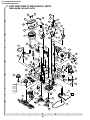
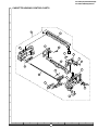
11. EXPLODED VIEW OF MECHANICAL PARTS ........................................................................... 80
12. PACKING OF THE SET .............................................................................................................. 85
VC-H961U ...................... Models for Canada
VC-A560U(A)/A560U/A560U(B)/H960U/H960U(B) ................. Models for U.S.A
SHARP CORPORATION
This document has been published to be used for
after sales service only.
1The contents are subject to change without notice.
VC-A560U(A)/A560U/A560U(B)
VC-H960U/H960U(B)/H961U
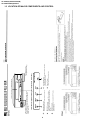
IMPORTANT SERVICE NOTES
etc.) and measure the AC voltage drop across the
resistor. Reverse the AC plug on the set and repeat
AC voltage measurements for each exposed part.
Any reading of 0.45V rms (this corresponds to 0.3mA
rms AC.) or more is excessive and indicates a potential shock hazard which must be corrected before
returning the video cassette recorder to the owner.
BEFORE RETURNING THE VIDEO CASSETTE
RECORDER
Before returning the video cassette recorder to the user,
perform the following safety checks.
1. Inspect all lead dress to make certain that leads are
not pinched or that hardware is not lodged between
the chassis and other metal parts in the video cassette
recorder.
2. Inspect all protective devices such as non-metallic
control knobs, insulation materials, cabinet backs,
adjustment and compartment covers or shields, isolation resistor/capacitor networks, mechanical insulators etc.
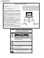
3. To be sure that no shock hazard exists, check for
current in the following manner.
● Plug the AC line cord directly into a 120 volt AC outlet
(Do not use an isolation transformer for this test).
● Using two clip leads, connect a 1.5k ohm, 10 watt
resistor paralleled by a 0.15µF capacitor in series with
all exposed metal cabinet parts and a known earth
ground, such as a water pipe or conduit.
● Use an SSVM or VOM with 1000 ohm per volt, or
higher, sensitivity or measure the AC voltage drop TO EXPOSED
across the resistor (See Diagram).
METAL PARTS
● Move the resistor connection to earth exposed metal
part having a return path to the chassis (antenna,
metal cabinet, screw heads, knobs and control shafts,
SSVM
AC SCALE
1.5k ohms.
10W
0.15 µF
TEST PROBE
WARNING :TO REDUCE THE RISK OF FIRE OR ELECTRIC SHOCK, DO NOT EXPOSE THIS APPLIANCE TO RAIN OR MOISTURE.
CAUTION
RISK OF ELECTRIC SHOCK
DO NOT OPEN
CAUTION: TO REDUCE THE RISK OF ELECTRIC SHOCK. DO
NOT REMOVE COVER. NO USER-SERVICEABLE
PARTS INSIDE. REFER SERVICING TO QUALIFIED
SERVICE PERSONNEL.
This symbol warns the user of uninsulated voltage
within the unit that can cause dangerous electric shocks.
This symbol alerts the user that there are important
operating and maintenance instructions in the literature
accompanying this unit.
CAUTION:
3.0A 125V
This symbol mark means fast operating fuse.
For continued protection against risk of fire, replace
only with same type fuse F901 (3.0A, 125V).
2
CONNECT TO
KNOWN EARTH
GROUND
VC-A560U(A)/A560U/A560U(B)
VC-H960U/H960U(B)/H961U
NOTES DE SERVICE IMPORTANTES
pièces métalliques exposées ayant un parcours de
retour au châssis (connexions d’antenne, coffret
métallique, tétes de vis, boutons et arbres de
commande, etc.) et mesurer la chute de tension CA
entre la résistance. Inverser la fiche CA (une fiche
intermédiaire non polarisée doit être utilisée à seule fin
de faire ces vérifications.) sur l’appareil et répéter les
mesures de tension CA pour chaque piéce métallique
exposée. Toute lecture de 0,45 Vrms (ceci correspond
à 0,3 mArms CA) ou plus est excessive et signale un
danger de choc qui doit être corrigé avant de rendre le
magnétoscope à son utilisateur.
AVANT DE RENDRE LE MAGNETOSCOPE
Avant de rendre le magnétoscope à l’utilisateur, effectuer
les vérifications de sécurité suivantes.
1. Vérifier toutes les gaines de fil pour être sûr que les fils
ne sont pas pincés ou que le matériel n’est pas coincé
entre le châssis et les autres pièces métalliques dans
le magnétoscope.
2. Vérifier tous les dispositifs de protection tels que les
boutons de commande non métalliques, les matériaux
d’isolement, le dos du coffret, les couvercles de
compartiment et ajustement ou les boucliers, les
réseaux de résistance / condensateur d’isolement, Ies
isolateurs mécaniques, etc.
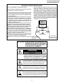
3. Pour être sûr qu’il n’y a aucun risque de choc électrique,
vérifier le courant de fuite de la maniére suivante.
● Brancher le cordon d’alimentation secteur directement
dans une prise de courant de 120 volts. (Ne pas utiliser
de transformateur d’isolement pour cet essai).
● Utiliser deux fils à pinces et connecter une résistance
de 10 watts 1,5 kohm en parallèle avec un condensateur
de 0,15 µF en série avec des pièces du coffret
métallique exposées et une masse de terre connue
telle qu’un tuyau ou un conduit d’eau.
● Utiliser un VTVM ou VOM avec une sensibilité de 1000
ohms par volt ou plus ou mesurer la chute de tension
CA entre la résistance (voir diagramme).
● Déposer la connexion de la résistance à toutes les VERS PIECES
VTVM
ECHELLE CA
1,5 KOHMS
10W
0,15 µF
SONDE D'ESSAI
METALLIQUES
EXPOSEES
ATTENTION: POUR REDUIRE LES RESQUES D'INCENDIE OU DE CHOC ELECTRIQUE,
NE PAS EXPOSER CET APPAREIL A
LA PLUIE OU A L'HUMIDITE.
ATTENTION
RISQUE DE CHOC ELECTRIQUE
NE PAS OUVRIR
ATTENTION: AFIN DE REDUIRE LES RISQUES DE CHOC
ELECTRIQUE, NE PAS RETIRER LE COUVERCLE,
AUCUN ORGANE INTERNE NE PEUT ETRE
REPARE PAR L'UTILISATEUR. CONFIER
L'APPAREIL A UN DEPANNEUR QUALIFIE.
Ce symbole signale à l'utilisateur la présence d'une
tension non isolée à l'intérieur de l'appareil qui peut être
la cause de secousses électriques dangereuses.
Ce symbole avertit l'utilisateur que des instructions
importantes relatives à l'utilisation et àl'entretien se
trouvent dans le manuel accompagnant l'appareil.
PRECAUTION:
Cette marque indique le fusible à action in stantansée.
Pour la protection continue contre le risque d'incendie,
ne remplacer que par le fusible type F901 (3,0A, 125V).
3,0A 125V
3
CANNECTER A
UNE MASSE DE
TERRE CONNUE
VC-A560U(A)/A560U/A560U(B)
VC-H960U/H960U(B)/H961U
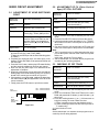
PRECAUTIONS IN PART REPLACEMENT
When servicing the unit with power on, be careful to the section marked white all over.
This is the primary power circuit which is live.
When checking the soldering side in the tape travel mode, make sure first that the tape has been loaded and then turn
over the PWB with due care to the primary power circuit.
Make readjustment, if needed after replacement of part, with the mechanism and its PWB in position in the main frame.
(1) Start and end sensors: Q701 and Q702
Insert the sensor’s projection deep into the upper hole of the holder. Referring to the PWB, fix the sensors tight
enough.
(2) Photocoupler: IC901
Refer to the symbol on the PWB and the anode marking of the part.
(3) Cam switches A and B: S704: QSW-RA001WJZZ.
Adjust the notch of the part to the white marker of the symbol on the PWB. Do not allow any looseness.
(4) Take-up and supply sensors: D707 and D706.
Be careful not to confuse the setting direction of the parts in reference to the symbols on the PWB. Do not allow any
looseness.
4
VC-A560U(A)/A560U/A560U(B)
VC-H960U/H960U(B)/H961U
1. GENERAL INFORMATION
1-1 FEATURES
Only for VC-H960U/H960U(B)/H961U
•
Hi-Fi Stereo Sound
• Built-in MTS (Multi-channel TV Sound) Decoder
Only for VC-H961U
• Built-in Front AV Jacks
•
•
•
•
•
•
•
•
•
•
•
•
•
•
•
•
•
Common Features
• EZ Set Up
• S-VHS Quasi Playback
• Double-Azimuth 4-Heads
• 19µ Clear Picture System (in EP mode)
• HQ System for Better Resolution and Color Reproduction
• Multi-Language (English/Spanish/French) OSD (On Screen
Display) with Menu Screen Guidance
• 181-channel PLL Quartz Synthesized Random Access Tuner
with Automatic Channel Setting
• Quick Start with Full Loading Mechanism
• 1-Year, 8 Event Programmable Timer
Simple Recording Timer
Universal Remote Control
Sharp Super Picture
5 sec. Timer Backup
Field-Still/Variable Slow/Frame Advance
Real-Time Counter (On Screen Display)
Automatic Daylight Saving-Time (D.S.T.) Adjustment
Blue Screen Noise Elimination
Auto Tracking Control System
Digital Program Search System (DPSS)
Skip Search
Instant Replay
Auto Zero Back
Recorded Section Auto Repeat
Full Automatic Playback
Tamper Proof
Up to 8 Hours of Recording and Playback (with T-160
cassette)
1-2 SPECIFICATIONS
Format:
Video Recording System:
Number of Video Heads:
Video Signal Standard:
Audio Recording System:
Tape Width:
Tape Speed:
Maximum Recording Time:
Channel Coverage:
Antenna Input:
Video Input:
Video Output:
Audio Input:
Audio Output:
Hi-Fi Audio (Only for Hi-Fi models):
Dynamic Range:
Frequency Response:
Memory Backup:
Operating Temperature:
Storage temperature:
Power Source:
Power Consumption:
Dimensions (approx.):
Weight (approx.):
Accessories included:
VHS NTSC Standard
Rotary Two-Head Helical Scan System
4
NTSC Color System
1 Stationary Head for Linear Audio
2 Rotary Heads for Hi-Fi stereo (Only for Hi-Fi models)
12.7 mm (1/2 inch)
(SP) 33.35 mm/sec. (1.31 i.p.s.)
(LP) 16.67 mm/sec. (0.66 i.p.s.) (playback only)
(EP) 11.12 mm/sec. (0.44 i.p.s.)
(SP) 160 min. (T-160)
(EP) 480 min. (T-160)
VHF 2-13
UHF 14-69
CATV 1-125
75 Ohm
0.5 to 2.0 Vp-p, 75 Ohm unbalanced
1.0 Vp-p, 75 Ohm unbalanced
–8 dBs, 47 kOhm unbalanced (0 dBs = 0.775 Vrms)
–8 dBs, 1 kOhm unbalanced (0 dBs = 0.775 Vrms)
90 dB
20 Hz-20 kHz
5 sec.
5°C to 40°C (41°F to 104°F)
–20°C to 60°C (–4°F to 140°F)
120 V AC, 60 Hz
14 W
360 (W) x 92.5 (H) x 229 (D) mm (14-3/16" x 3-41/64" x 9-1/64")
2.3 kg (5.1 lbs)
75 ohm coaxial cable, Operation manual, Infrared remote control, Battery (2 pcs.)
Note: Specifications are subject to change without notice.
5
(VC-H961U)
6
3
2
1
Basic function controls
(see Playback/Recording)
2
1
This indicator lights up when selecting "VCR" by using
the TV/VCR button.
VCR LED indicator
Point Remote Control at this window.
Remote Sensor
This indicator lights up when the VCR is set for timer
recording, Simple Recording Timer and Recording with
the Timer.
5
REC LED indicator
5
REMOTE SENSOR
TIMER LED indicator
4
4
REC
This indicator lights up on during recording. This indicator
flashes during REC-Pause.
3
VCR
This indicator lights up whenever the VCR is turned on.
POWER LED indicator
TIMER
POWER
LED Indicator (explained throughout the operation Instruction)
POWER button
(When pressed to turn on the VCR, POWER LED indicator
will light up. When the power is turned off. POWER LED
indicator wil turn off.)
Cassette compartment (see Playback/Recording)
VC-A560U(A)/A560U/A560U(B)
VC-H960U/H960U(B)/H961U
1-3 LOCATION OF MAJOR COMPONENTS AND CONTROL
VC-A560U(A)/A560U/A560U(B)
VC-H960U/H960U(B)/H961U
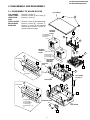
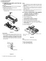
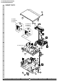
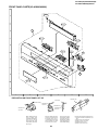
2. DISASSEMBLY AND REASSEMBLY
2-1 DISASSEMBLY OF MAJOR BLOCKS
TOP CABINET
TOP CABINET
FRONT PANEL
OPERATION
PWB
SHIELD ANGLE
MECHANISM/
MAIN PWB
: Remove 2 screws 1.
: Remove 2 screws 2 and 7 clips 3.
: Remove 1 screw 4.
1
: Remove 1 screw 5 with shield angle.
: Remove 1 screw 6, 2 screws 7.
Remove 1 screw 8 with antenna
terminal cover. Remove 1 screw 9
with top cabinet fix angle.
VC-H960U
VC-H960U(B)
VC-H961U
ANTENNA
TERMINAL
COVER
C
6
2
2
8
6
8
ANTENNA
TERMINAL
COVER
7
B
VC-A560U(A)
VC-A560U
VC-A560U(B) 3
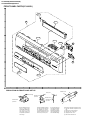
Front Panel
B
7
A
MECHANISM/
MAIN PWB
ASSEMBLY
FRONT AV
JACK
A
A
C
B
3
9
VC-H961U
VC-H961U
TOP CABINET
FIX ANGLE
LED HOLDER
3
Front Panel
B
B
A
6
B
A
3
VC-A560U(A)
VC-A560U
VC-A560U(B)
VC-H960U
VC-H960U(B) OPERATION PWB
MAIN FRAME
4
B
7
VC-A560U(A)/A560U/A560U(B)
VC-H960U/H960U(B)/H961U
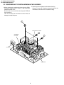
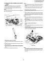
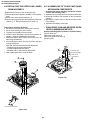
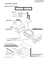
2-2 DISASSEMBLING THE MECHANISM/MAIN PWB ASSEMBLY
2. Removing the mechanism and cassette housing.
Remove 2 screws 3 fixing the cassette housing to the
mechanism, and remove the cassette housing.
1. When removing the mechanism from the main PWB,
remove the antenna cover 1 screw 1, and remove the
antenna terminal cover.
Remove the screw 2 which connecting the PWB and
the mechanism.
Take out vertically the mechanism so that it does not
damage the adjacent parts.
3
MECHANISM CHASSIS
1
CASSETTE
HOUSING
2
VC-H961U
MAIN PWB
8
VC-A560U(A)/A560U/A560U(B)
VC-H960U/H960U(B)/H961U
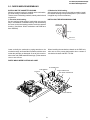
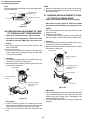
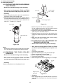
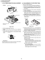
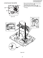
2-3 CARES WHEN REASSEMBLING
INSTALLING THE CASSETTE HOUSING
When the cassette housing is installed on the mechanism,
the initial setting is essential condition.
There are two initial setting methods, namely electrical and
mechanical.
1. Electrical initial setting
So as to perform initial setting of mechanism execute the
Step 1 of Installation of cassette housing. After ascertaining
the return to the initial setting position install the cassette
housing. (Conditions: When mechanism and PWB have
been installed)
2. Mechanical initial setting
After ascertaining the return to the initial set position install
the cassette housing in the specified position. (This method
is applied only for the mechanism.)
INSTALLING THE MECHANISM ON PWB
Master cam
Push up
Drive lever
Lower vertically the mechanism, paying attention to the
mechanism edge, and install the mechanism with due care
so that the parts are not damaged. So as to fix the mechanism to the main PWB install two housings. (Fit the antenna
cover to one of them.
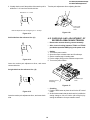
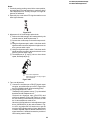
When installing the mechanism chassis on the PWB unit,
take care so as to prevent deformation due to contact of
mechanism chassis with REC TIP SW.
PARTS WHICH NEED PARTICULAR CARE
AE CONNECTOR
END SENSOR
DRUM CONNECTOR
VC-H961H
AC HEAD CONNECTOR
END TIP SW
START SENSOR
9
VC-A560U(A)/A560U/A560U(B)
VC-H960U/H960U(B)/H961U
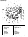
3. FUNCTION OF MAJOR MECHANICAL PARTS (TOP VIEW)
17
18
15
10
16
14
1
9
2
11
3
5
7
8
6
No.
4
12
Function
13
No.
Function
1
Full erase head
10
A/C head ass’y
2
Supply pole base ass’y
11
Reverse guide lever ass’y
3
Tension arm
12
Reel relay gear
4
Idler wheel ass’y
13
Take-up reel disk
5
Open guide
14
Pinch roller lever ass’y
6
Supply reel disk
15
Drum ass'y
7
Supply main brake
16
Loading motor block
8
Take-up main brake
17
Drum driver motor
9
Pinch drive cam
18
Take-up pole base ass'y
10
VC-A560U(A)/A560U/A560U(B)
VC-H960U/H960U(B)/H961U
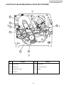
FUNCTION OF MAJOR MECHANICAL PARTS (BOTTOM VIEW)
21
22
25
19
20
23
No.
24
Function
No.
Function
19
Syncro Gear
23
Clutch lever
20
Master cam
24
Limiter pulley ass’y
21
Capstan D.D. motor
25
Shifter
22
Reel belt
11
VC-A560U(A)/A560U/A560U(B)
VC-H960U/H960U(B)/H961U
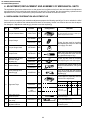
4. ADJUSTMENT, REPLACEMENT AND ASSEMBLY OF MECHANICAL UNITS
The explanation given below relates to the on-site general service (field service) but it does not relates to the adjustment
and replacement which need high-grade equipment, jigs and skill. For example, the drum assembling, replacement and
adjustment service must be performed by the person who have finished the technical courses.
4-1 MECHANISM CONFIRMATION ADJUSTMENT JIG
So as to perform completely the mechanism adjustment prepare the following special jigs. So as to maintain the initial
performance of the machine the maintenance and check are necessary. Utmost care must be taken so that the tape is
not damaged. If adjustment needs any jig, be sure to use the required jig.
No.
Jig ltem
Part No.
Code
1.
Torque Cassette Meter
JiGVHT-063
CZ
JiGTG0090
CM
2.
Torque Gauge
JiGTG1200
CN
3.
Torque Gauge Head
JiGTH0006
AW
4.
Torque Driver
JiGTD1200
CB
Master Plane Jig and
Reel Disk Height
Adjusting Jig
JiGRH0002
BR
5.
JiGMP0001
BY
JiGSG2000
BS
JiGSG0300
BF
JiGADP003
BK
6.
7.
Configuration
This cassette torque meter is used for checking and adjusting the torque of take-up for
measuring tape back tension.
These Jigs are used for checking
and adjusting the torque of take-up
and supply reel disks.
When fixing any part to the threaded
hole using resin with screw, use the
jig. (Specified torque 5 kg)
These Jigs are used for checking
and adjusting the reel disk height.
There are two gauges used for the
tension measurements, 300 g and
2.0 kg.
Tension Gauge
Pinch pressing force
measuring jig
Remarks
This Jig is used with the tension
gauge. Rotary transformer clearance
adjusting jig.
These tapes are especially used for
electrical fine adjustment.
Video
8.
9.
Alignment Tape
Guide roller height
adjustment driver
10.
X value adjustment
gear driver
11.
Tension Pole
Adjustment Driver
VROATSV
CD
VROEFZCS
OR
VROEFZHS
BG
Track
7k
—
58µm
NTSC Color Bar
1k
—
58µm
—
19µm
1k
2.3k
This screwdriver is used for adjusting the
guide roller height.
JiGDRiVERH-4 AP
JiGDRiVER-6
HiFi Audio
525 Monoscope
Black Level
(only SYNC) signal
BH
Audio
For X value adjustment
BM
This Jig is used for adjustment
of tension pole.
12
VC-A560U(A)/A560U/A560U(B)
VC-H960U/H960U(B)/H961U
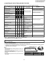
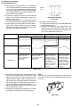
4-2 MAINTENANCE CHECK ITEMS AND EXECUTION TIME
Perform the maintenance with the regular intervals as follows so as to maintain the quality of machine.
Maintained 500 1000 1500 2000 Possible symptom
Remarks
encountered
hrs. hrs. hrs. hrs.
Parts
Abnormal rotation or significant
Guide roller ass’y
vibration requires replacement.
Sup guide shaft
Reverse guide
Lateral noises Head
occasionally blocked
Clean tape contact part with the
specified cleaning liquid.
Slant pole on pole base
Full erase head
A/C head
Upper and lower drum ass’y
Capstan D.D. motor
Pinch roller
Reel belt
Colour and beating
Small sound or sound
distortion
Poor S/N ratio, no colour
Poor flatness of the
envelope with alignment
tape
No tape running,
uneven colour
No tape running, tape
slack
No tape running, tape
slack, no fast forward/
rewind motion
Tension band ass’y
Screen swaying
Loading motor
Cassette not loaded or
unloaded
Idler ass’y
Limiter pulley
Supply/take-up main brake levers
Clean tape contact area with the
specified cleaning liquid.
Clean rubber and rubber contact
area with the specified cleaning
liquid.
No tape running, tape
slack
Tape slack
NOTE
: Part replacement.
: Cleaning
: Apply grease
<Specified> Cleaning liquid Industrial ethyl alcohol
* This mechanism does not need electric adjustment with variable resistor. Check parts. If any deviation is found,
clean or replace parts.
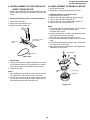
Video head cleaning procedure
1. Apply one drop of cleaning liquid to the cleaning paper with the baby oiler.
2. Gently press the cleaning paper against the video head to fix your finger, and move the upper drum so that each head
is passed to and fro 5 times (do not move the cleaning paper).
3. Wipe with the dry cleaning paper.
Rotate the upper drum
with one hand.
Notes :
• Use the commercially available ethanol of Class 1 as
cleaning liquid.
• Since the video head may be damaged, do not move up
and down the cleaning paper.
• Whenever the video head is cleaned, replace the cleaning paper.
• Do not apply this procedure for the parts other than the
video head.
Gently press the cleaning paper to
fix with your finger, and rotate the
upper drum to clean.
Move to and fro 5 times for each head.
(Do not move the cleaning paper.)
Parts Code
ZPAPRA56-001E
ZOiLR-02-24TE
13
Description
Cleaning Paper
Babe Oiler (Spoit)
Code
AW
AH
VC-A560U(A)/A560U/A560U(B)
VC-H960U/H960U(B)/H961U
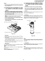
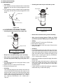
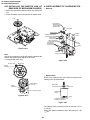
4-3 REMOVING AND INSTALLING THE CASSETTE HOUSING
Notes:
1. In the case when you use the magnet screw driver, never
approach the magnet driver to the A/C head, FE head,
and drum.
2. When installing or removing, take care so that the
cassette housing control and tool do not contact the
guide pin or drum.
3. After installing the cassette housing control once perform cassette loading operation.
• Removal
1. In the cassette removing mode, remove the cassette.
2. Unplug the power cord.
3. Remove in the following numerical order.
a) Remove two screws 1.
b) Pull the drive lever slide and pull up the cassette
housing control.
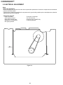
4-4 TO RUN A TAPE WITHOUT THE CASSETTE
HOUSING CONTROL ASSEMBLY
1
1.
2.
3.
4.
Remove the full-surface panel.
Short-circuit between TP803 and TP802.
Plug in the power cord.
Turn off the power switch.
(The pole bases move into U.L.position.)
5. Open the lid of a cassette tape by hand.
6. Hold the lid with two pieces of vinyl tape.
7. Set the cassette tape in the mechanism chassis.
8. Stabilize the cassette tape with a weight (500g) to
prevent floating.
9. Turn on the power switch.
10. Perform running test.
500g
Figure 4-1.
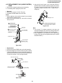
• Reassembly
1. Before installing the cassette housing control, shortcircuit between TP803 and TP802 provided at main
PWB, press the eject button. The master cam turns and
stops when the positioning mark appears. Fit the drive
lever to master cam through main chassis, and push up
the drive lever.
Mechanism chassis
Weight to prevent
float (500g)
Figure 4-3.
Note:
The weight should not be more than 500g.
To take out the cassette tape.
1. Turn off the power switch.
2. Take out the cassette tape.
Master cam
Push up
Drive lever
Figure 4-2.
2. Install in the reverse order of removal.
14
VC-A560U(A)/A560U/A560U(B)
VC-H960U/H960U(B)/H961U
4-5 REEL DISK REPLACEMENT AND HEIGHT
CHECK
Notes:
1. When installing the reel disk, take due care so that the
tension band ass'y is not deformed and grease does no
adhere.
2. Do not damage the Supply main brake ass'y. Be careful
so that grease does not adhere to the brake surface.
• Removal
1. Remove the cassette housing control assembly.
2. Remove the Supply/Take-up main brake ass'y.
3. Pull the tension band out of the tension arm ass'y.
4. Remove the reel disk.
Note:
Take care so that the tension band ass'y and main brake
ass'y are not deformed.
• Reassembly (Take-up reel disk)
1. Clean the reel disk shaft and apply grease (SC-141) to
it.
2. Align the phase of the reel disk to that of the reel relay
gear and to install a new take-up reel disk onto the shaft.
3. Check the reel disk height and reassemble the take-up
main brake ass'y.
Note:
1. Take care so that the Take-up main brake ass'y is not
damaged. Take care so that grease does not adhere the
brake surface.
2. After reassembly, check the video search rewind back
tension (see 4-10), and check the brake torque (see 414).
Tension
Take-up main brake ass'y
Ten arm ass'y
Supply main brake
Tension band
ass'y
Supply reel disk
• Height checking and adjustment
Note:
1. Set the master plane with due care so that it does not
contact the drum.
2. When putting the master plane, shift the reverse guide
a little in the loading direction. Care must be taken since
excessive shift results in damage.
Take-up reel disk
Master plane
• Reassembly (Supply reel disk)
1. Clean the reel disk shaft and apply grease (SC-141) to
it.
2. Match the phases of reel disk and reel relay gear, and set
the new reel disk.
3. After checking the reel disk height, wind the tension
band ass'y around the reel disk, and hook to tension arm
ass'y.
4. Assemble the Supply main brake ass'y.
Supply reel disk
Cassette lock
release shaft
Take-up reel disk
Figure 4-4.
Note:
• Check that the reel disk is lower than part A but higher
than part B. If the height is not correct, readjust the reel
disk height by changing the poly-slider washer under the
reel disk.
15
VC-A560U(A)/A560U/A560U(B)
VC-H960U/H960U(B)/H961U
Note:
Whenever replacing the reel disk, perform the height checking and adjustment.
Reel disk height
adjusting jig
Master plane
10 ± 0.2mm
Notes:
1. Hold the torque gauge by hand so that it is not moved.
2. Do not keep the reel disk in lock state. Do not allow longtime measurement.
4-7 CHECKING AND ADJUSTMENT OF TAKEUP TORQUE IN REWIND MODE
Mechanism chassis
Reel disk
• Remove the cassette housing control assembly.
A
B
• After short-circuiting between TP803 and TP802
provided at operation PWB, plug in the power cord.
Reel disk
Figure 4-5.
• Setting
1. Set a torque gauge to zero on the scale. Place it on the
supply reel disk.
2. Press the rewind button.
3. To calculate the remaining capacity, slowly rotate the
take-up reel disk, and then shift it into the rewind mode.
4-6 CHECKING AND ADJUSTMENT OF TAKEUP TORQUE IN FAST FORWARD MODE
• Remove the cassette housing control assembly.
• After short-circuiting between TP803 and TP802
provided at operation PWB, plug in the power cord.
• Checking
1. Turn the torque gauge slowly (one rotation every 2 to 3
seconds) by hand in the CCW direction.
2. Make sure that the indication of torque gauge is not less
than 30mN·m (306gf·cm).
• Setting
1. Set a torque gauge to zero on the scale. Place it on the
take-up reel disk.
2. Press the FF button.
3. To calculate the remaining capacity of the play back
mode, slowly rotate the supply reel disk, and then shift
it into the forward mode.
Torque gauge
30mN·m (306gf·cm)
or more
• Checking
1. Turn the torque gauge slowly (one rotation every 2 to 3
seconds) by hand in the CW direction.
2. Make sure that the indication of torque gauge is not less
than 30mN·m (306gf·cm).
CCW
The gauge is held at
its maximum value.
(Red mark)
Torque gauge
Supply reel disk
CW
30mN·m (306gf·cm)
or more
The gauge is held at
its maximum value.
(Red mark)
Idler ass'y
Figure 4-7.
• Adjustment
1. If the rewind winding-up torque is less than the specified
value, clean the capstan D.D. worm gear, drive belt, and
limiter pulley with cleaning liquid, rewind again, and
check the winding-up torque.
2. If the winding-up torque is still out of range, replace the
drive belt.
Idler ass'y
Figure 4-6.
• Adjustment
1. If the FF winding-up torque is less than the specified
value, clean the capstan D.D. worm gear, drive belt, and
limiter pulley with cleaning liquid, and check again.
2. If the torque is less than the set value, replace the reel
belt.
16
VC-A560U(A)/A560U/A560U(B)
VC-H960U/H960U(B)/H961U
Notes:
1. Hold the torque gauge by hand so that it is not moved.
2. Do not keep the reel disk in lock state. Do not allow longtime measurement.
4-9 CHECKING AND ADJUSTMENT OF TAKEUP TORQUE IN VIDEO SEARCH REWIND
MODE
4-8 CHECKING AND ADJUSTMENT OF TAKEUP TORQUE IN RECORD/PLAYBACK
MODE
• After short-circuiting between TP803 and TP802
provided at operation PWB, plug in the power cord.
• Remove the cassette housing control assembly.
• Setting
Press the playback button and rewind button to set the
video search rewinding mode.
• Remove the cassette housing control assembly.
• After short-circuiting between TP803 and TP802
provided at operation PWB, plug in the power cord.
• Turn off the power switch.
• Open the cassette torque meter lid, and fix it with
tape.
• Load the cassette torque meter into the unit.
• Put the weight (500g) on the cassette torque meter.
• Turn on the power switch.
• Press the picture record button, and set EP picture
record mode (x3).
• Checking
Place the torque gauge on the supply reel disk, and turn it
counterclockwise very slowly (one rotation every 1 to 2
seconds) and check that the torque is within the set value
change to 14.1 ± 3.5mN⋅m. (144 ± 35gf⋅cm)
Torque gauge
+20
Set value EP change to 6.9 +2.0
–2.5 mN⋅m (70 –25gf⋅cm)
CCW
500g
Cassette torque meter
Supply reel disk
Figure 4-8.
• Checking
1. Make sure that value is within the setting 6.9 +2.0
–2.5 mN·m
(70+20
–25 gf·cm).
2. The winding-up torque fluctuates due to variation of
rotation torque of limiter pulley ass'y. Read the center
value of fluctuation as setting.
3. Set the EP record mode (x3) and make sure that the
winding-up torque is within setting.
Figure 4-9.
Note:
Surely put the torque gauge on the reel disk to measure. If
the torque gauge is raised, accurate measurement is
impossible.
• Adjustment
If the rewinding playback winding-up torque is not within the
setting, replace the limiter pulley assembly.
• Adjustment
If the playback winding-up torque is not within the setting,
replace the limiter pulley assembly.
Note:
When the torque cassette is set, put a weight (500g) to
prevent rise.
When the cassette torque meter is taken out.
Turn off the power switch.
Note:
The winding-up torque fluctuates due to variation of rotation torque of supply reel disk. Read the center value of
fluctuation as setting.
17
VC-A560U(A)/A560U/A560U(B)
VC-H960U/H960U(B)/H961U
4-10 CHECKING THE VIDEO SEARCH REWIND
BACK TENSION
• Remove the cassette housing control assembly.
• After short-circuiting between TP803 and TP802
provided at operation PWB, plug in the power cord.
Tension gauge
900 - 1,200gf
Pinch roller
• Checking
1. After pressing the play button, press the rewind button,
and set the video search rewind mode.
2. Place the torque gauge on the take-up reel disk, and turn
it counterclockwise very slowly (one rotation every 2 to
3 seconds) and check that the torque is within the set
value 3.4 ± 1.5mN⋅m (35 ± 15gf⋅cm).
Capstan shaft
Tension gauge adapter
Figure 4-11.
Torque gauge
1. Detach the pinch roller from the capstan shaft.
Do not separate excessively. Or the pinch lever and
pinch double action lever may disengage.
2. Engage the tension gauge adapter with the pinch roller
shaft, and pull in the arrow direction.
3. Gradually return the pinch roller, and measure the
pulling force when the pinch roller contacts the capstan
shaft.
4. Make sure that the measured value is within setting
change to 9.8 ± 1N (1.0 ± 0.1kgf).
CCW
Take-up reel disk
4-12 CHECKING AND ADJUSTMENT OF
TENSION POLE POSITION
• Remove the cassette housing control assembly.
Figure 4-10.
• After short-circuiting between TP803 and TP802
provided at operation PWB, plug in the power cord.
Notes:
Set the torque gauge securely on the take-up reel disk.
If it is not secure, the measurement will be incorrect.
•
1.
2.
3.
4.
5.
6.
4-11 C H E C K I N G T H E P I N C H R O L L E R
PRESSURE
• Remove the cassette housing control assembly.
• After short-circuiting between TP803 and TP802
provided at operation PWB, plug in the power cord.
Setting
Turn off the power switch.
Open the cassette tape (T-120), and fix with tape.
Set the cassette tape in loading state.
Put the weight (500g) on the cassette tape.
Turn on the power switch.
Make the adjustment with the beginning of a T-120 tape.
(T-120)
• Checking
Press the play button to set the playback mode.
500g
Weight to prevent
float (500g)
Figure 4-12.
• Checking
1. Set a cassette tape, push the REC button to place the
unit in the SP record mode. Now check the tension pole
position.
18
VC-A560U(A)/A560U/A560U(B)
VC-H960U/H960U(B)/H961U
2. Visually check to see if the position of the tension pole is
within the 0 ± 0.2mm from the left side line.
Tension pole adjustment driver adjusting direction
CW
CC
W
Standard A = 0 ± 0.2mm
A
Tension pole
adjustment
driver
Make the adjustment with the beginning of a T-120 tape.
Figure 4-16.
Figure 4-13.
At left side from the reference line. (A).
4-13 CHECKING AND ADJUSTMENT OF
RECORD/PLAYBACK BACK TENSION
• Remove the cassette housing control assembly.
• After short-circuiting between TP803 and TP802
provided at operation PWB, plug in the power cord.
•
1.
2.
3.
4.
5.
A
Figure 4-14.
Setting
Turn off the power switch.
Open the torque cassette meter and fix with tape.
Set the cassette tape in loading state.
Put the weight (500g) on the cassette torque meter.
Turn on the power switch.
Insert the tension pole adjustment driver, and rotate
counterclockwise.
At right side from the reference line. (A).
500g
Cassette torque
meter
Weight to prevent
float (500g)
Figure 4-17.
A
• Checking
1. Push the REC button to place the unit in the SP record
mode.
2. At this time ascertain that the back tension is within the
setting change to 3.9 to 5.5mN⋅m (40 to 56gf·cm) by
seeing the indication of torque cassette meter.
Figure 4-15.
Insert the tension pole adjustment driver, and rotate clockwise.
19
VC-A560U(A)/A560U/A560U(B)
VC-H960U/H960U(B)/H961U
• Adjustment
1. If the indication of torque cassette meter is lower than
the setting, shift the tension spring engagement to the
part A.
2. If the indication of torque cassette meter is higher than
the setting, shift the tension spring engagement to the
part B.
A
• Checking the brake torque at the take-up side
Torque gauge
Tension arm
B
CW
CCW
Take-up reel
disk
Tension spring
CCW: 4.41 ± 1.5mN⋅m (45 ± 15gf⋅cm)
CW:
4.12 ± 1.2mN⋅m (42 ± 12gf⋅cm)
Figure 4-18.
4-14 CHECKING THE BRAKE TORQUE
• Checking the brake torque at the supply side
Figure 4-20.
• Remove the cassette housing control assembly.
Torque gauge
CCW
• After short-circuiting between TP803 and TP802
provided at operation PWB, plug in the power cord.
CW
•
1.
2.
3.
Supply reel disk
Setting
Switch from the FF mode to the STOP mode.
Disconnect the power cord.
Set a torque gauge to zero on the scale. Place it on the
take-up reel disk.
• Checking
1. Turn the torque gauge at a rate of about one turn/2 sec
in the CCW direction/CW direction so that the reel disk
and torque gauge pointer rotates at equal speed and
make sure that the value is within the setting (CCW
direction: 4.41 ± 1.5mN·m (45 ± 15gf·cm), CW direction:
4.12 ± 1.2mN·m (42 to 12gf·cm).
CCW: 4.41 ± 15mN⋅m (45 ± 15gf⋅cm)
CW:
4.12 ± 1.2mN⋅m (42 ± 12gf⋅cm)
Figure 4-19.
• Remove the cassette housing control assembly.
• After short-circuiting between TP803 and TP802
provided at operation PWB, plug in the power cord.
2. Adjustment of the brake torque at the supply side and the
take-up side
• Unless the supply side brake torque or take-up side
brake torque is within the setting, clean the felt surface
of reel disk (supply, take-up) brake lever, check again
the brake torque.
• If value cannot be set within the setting yet, replace the
main brake ass'y or main brake spring.
• Setting
1. Set a torque gauge to zero on the scale. Place it on the
supply reel disk.
2. Switch from the FF mode to the STOP mode.
3. Disconnect the power cord.
• Checking
Turn the torque gauge at a rate of about one turn/2 sec
in the CW direction/CCW direction with respect to the
supply reel disk so that the reel disk and torque gauge
pointer rotate at equal speed, and make sure that the
value is within the setting (CW direction: 4.12 ± 1.2mN·m
(42 ± 12gf·cm); CCW direction: 4.41 ± 15mN·m (45 ±
15gf·cm).
20
VC-A560U(A)/A560U/A560U(B)
VC-H960U/H960U(B)/H961U
3. Align the left end of gear of A/C head arm with the
punched mark of chassis, tentatively tighten the screws
1 so as to ensure smooth motion of A/C head arm.
Tightening torque must be 0.45 ± 0.05N·m (4.5 ±
0.5kgf·cm).
4-15 REPLACEMENT OF A/C (AUDIO/CONTROL)
HEAD
1. Remove the cassette housing control assembly.
2. In unloading state unplug the power cord.
• Removal
1. Remove the screws 123, Tilt screw.
2. Unsolder the PWB fitted to the A/C head.
Notes:
1. When replacing, never touch the head. If you touched,
clean with the cleaning liquid.
2. When removing the screw 3, take care so that the
spring may out.
Height screw
1
3 AC head screw
Azimurh spring
Left end of A/C head arm gear
Punched line mark on chassis
Figure 4-23.
*Derection designation.
(The bottom part is big.)
Tilt screw
2 Azimuth adj. screw
Note:
1. If the screw 1 is tighten tentatively too loose, the
azimuth and height of A/C head may change when they
are finally tightened. Therefore care must be taken.
2. After completion of A/C head be sure to adjust tape
running. (Execute the running adjustment by the method
described in 4-17.)
AC head PWB
AC head PWB ass'y
(with A/E)
Height adj. screw
1
A/C head plate
Height Adj. spring
Figure 4-21.
• Replacement
1. Solder the removed PWB to the new head assembly.
2. Adjust the height from the A/C head arm (lower surface)
to the A/C head plate to 10.8mm with slide calipers. (3
places of azimuth screw section, tilt screw section and A/
C head front section) (See the figure below.)
New A/C head ass'y
AC head PWB
Solder
A/C head plate
*Fit the groove of FFC to
the boss of the holder.
A/C head FFC
A/C FFC holder
10.8mm
Figure 4-22.
21
VC-A560U(A)/A560U/A560U(B)
VC-H960U/H960U(B)/H961U
4-16 A/C HEAD HEIGHT ROUGH ADJUSTMENT
4-17 ADJUSTMENT OF TAPE DRIVE TRAIN
1. Tape run rough adjustment
1 Remove the cassette housing control assembly.
2 After shortcircuiting between TP803 and TP802 provided at operation PWB, plug in the power cord.
3 Check and adjust the position of the tension pole.
(See 4-12.)
4 Check and adjust the video search rewind back
tension. (See 4-10.)
5 Connect the oscilloscope to the test point for PB ATR
signal output (TP201). Set the synchronism of the
oscilloscope to EXT. The PB ATR signal is to be
triggered by the head switching pulse (TP202).
6 Set the alignment tape (VROATSV) to play. (Put a
500g weight on the cassette tape to prevent lift of
cassette tape.)
• Setting
Azimuth screw
TiH screw
Height screw
Cassette tape
Guide roller
Cassette Tape
500g
500g
Mechanism chassis
Weight to prevent
float (500g)
Weight of 500g
Figure 4-26.
Figure 4-24.
7 Press the tracking button (+), (–) and change the
ATR signal waveform from max to min and from min
to max. At this time make sure that the ATR signal
waveform changes nearly parallel.
8 Unless the ATR signal waveform changes nearly
parallel, adjust the height of supply side and take-up
side guide roller so that the envelope waveform
changes nearly parallel. (For ATR signal adjustment
procedure refer to Figure 4-30.)
9 Turn the tilt screw to remove the tape crease at the
fixing guide flange.
Playback the tape and check for tape crease at the
fixing guide flange.
(1) If there is no tape crease
Turn the tilt screw clockwise so that tape crease
appears once at the flange, and then return the tilt
screw so that the crease disappears.
(2) If there is tape crease
Turn counterclockwise the tilt screw so that the
tape crease disappears.
(Reference) If the tilt screw is turned clockwise
crease appears at the lower flange.
1. Set the cassette tape in the unit.
2. Press the PLAY button to put the unit in the playback
mode.
3. Roughly adjust the height of the A/C head by turning the
height screw until the tape is in the position shown
A/C head
below.
Tape
0.3mm
Figure 4-25.
• Adjustment
Adjust the height screw visually so that the control head is
visible 0.3mm below the bottom of the tape.
22
VC-A560U(A)/A560U/A560U(B)
VC-H960U/H960U(B)/H961U
Notes:
1. Previously set the tracking control in the center position,
and adjust the ATR signal waveform to maximum with X
value adjustment nut. Thereby the tape run rough adjustment is facilitated.
2. Especially the outlet side ATR signal waveform must
have higher flatness.
Figure 4-27.
2. Adjustment of A/C head height and azimuth
1 Perform the initial setting of A/C head position by the
method stated in "4-15 Replacement 3".
2 Connect the oscilloscope to the audio output terminal.
3 Using the alignment tape in which 1 kHz linear audio
signal has been recorded, adjust the height screw so
as to get max audio output.
4 Using the alignment tape in which 7 kHz linear audio
signal has been recorded, adjust the azimuth screw
so as to get max audio output.
5 The adjustment of 3 and 4 twice or three times
repeat, and finally adjust 4.
For X value adjustment
Adjust the X value, turning the geartype screwdriver.
Figure 4-28.
3. Tape run adjustment
1 Connect the oscilloscope to PB ATR signal output
test point, set oscilloscope sync to EXT, trigger-input
the PB CHROMA signal (head switching pulse).
2 Rough adjustment of X value
Tentatively fix A/C head arm screws 1 by the method
described in 4-15 "Replacement 3".
Playback the alignment tape (VROATSV) and
shortcircuit between TP801 and TP802. As a result
the auto-tracking is automatically cancelled, so that
the X value adjustment mode is set.
Move the A/C head with the X value adjustment gear
driver (JiGDRiVER-6) by the method shown in Figure 4-33, and adjust the A/C head so as to get the
maximum ATR signal waveform. (Note: When the A/
C head is adjusted, adjust so that the maximum ATR
signal waveform is obtained nearest the position of
initial setting made in 4-15.)
23
VC-A560U(A)/A560U/A560U(B)
VC-H960U/H960U(B)/H961U
3 Next, press the tracking button (+), (–) and change
the ATR signal waveform from max to min and from
min to max. At this time adjust the height of supply
and take-up side guide roller with the adjustment
driver (JiGDRiVERH-4) so that the ATR signal waveform changes nearly parallel.
4 If the tape is lifted or sunk from the helical lead
surface, the PB ATR signal waveform appears as
shown in Figure 4-30.
5 Press the tracking button (+), (–) and make sure that
the ATR signal waveform changes nearly parallel.
6 Finally, check tape crease near the reverse guide. If
tape crease is found, adjust tilt screw 45˚ counter
clockwise. Small tape crcase will appear at retain
guide after this adjustment finished.
PB ATR
Signal
Head switching pulse
Figure 4-29.
4. A/C head X value adjustment
1 Fix A/C head arm screws 1 by the method described
in 4-15 "Replacement 3".
2 Playback the alignment tape (VROATSV), and
shortcircuit between TP801 and TP802. As a result
the auto-tracking is automatically cancelled, so that
the X value adjustment mode is set.
When the tape is above the helical lead.
Supply side
Adjustment
Supply side guide roller
rotated in clockwise
direction (lowers guide
roller) to flatten
ATR signal.
Take-up side
Take-up side guide roller
rotated in clockwise
direction (lowers guide
roller) to flatten
ATR signal.
When the tape is below the helical lead.
Supply side
Take-up side
Supply side guide roller
rotated in counterclockwise direction (raises
guide roller) to make the
tape float above the helical
lead. The supply
side guide roller is then
rotated in the clockwise
direction to flatten the
ATR signal.
Take-up side guide roller
rotated in counterclockwise direction (raises
guide roller) to make the
tape float above the
helical lead. The take-up
side guide roller is then
rotated in the clockwise
direction to flatten the
ATR signal.
Figure 4-30.
3 Move the A/C head with the X value adjustment gear
driver by the method shown in Figure 4-33, and
adjust the A/C head so as to get the maximum ATR
signal waveform. (Note: At this time adjust so as to
get the maximum ATR signal waveform nearest the
A/C head position which has been set in case of X
value rough adjustment as stated in 4-17, 3- 2.)
4 Adjust the playback switching point (Refer to the
electric adjustment method.)
5 Playback the self-picture-recorded tape, and check
the flatness of ATR signal waveform and sound.
Notes:
When the A/C head X value adjustment is performed, be
sure to perform at first X value rough adjustment (refer to 417, 3-2).
1
Figure 4-31.
24
VC-A560U(A)/A560U/A560U(B)
VC-H960U/H960U(B)/H961U
4-19 REPLACEMENT OF DRUM D.D. MOTOR
4-18 REPLACEMENT OF THE CAPSTAN D.D.
(DIRECT DRIVE) MOTOR
1. Set the ejection mode.
2. Withdraw the main power plug from the socket.
• Remove the mechanism from the main PWB (refer to 22 item 1 When removing the mechanism from the main
PWB ).
•
1.
2.
3.
4.
5.
• Removal (Follow the order of indicated numbers.)
1. Remove the reel belt 1.
2. Remove the slow brake lever 2.
3. Remove the three screws 3.
Notes:
1. In removing the D.D. stator assembly, part of the drum
earth spring pops out of the pre-load collar.
Be careful not to lose it.
2. Install, so that the D.D. rotor ass'y and upper drum ass'y
mounting direction check holes align.
(Align the upper drum dent with the rotor hole.)
3. Be careful not to damage the upper drum or the video
head.
4. Protect the hole elements from shock due to contact with
D.D. stator or D.D. rotor ass'y.
5. After installation adjust the playback switching point for
adjustment of servo circuit.
3
Capstan D.D. motor
control PWB
Capstan D.D.
motor
Removal (Perform in numerical order.)
Disconnect the FFC cable 1.
Unscrew the D.D. stator assembly fixing screws 2.
Take out the D.D. stator assembly 3.
Unscrew the D.D. rotor assembly fixing screws 4.
Take out the D.D. rotor assembly 5.
2
1 Reel belt
D.D.stator ass'y
2
1
Figure 4-32.
4
• Reassembly
1. Taking care so that the capstan shaft does not contact
the mechanism chassis, set its position on the mechanism chassis, and then install with the three screws.
2. Install the reel belt.
4
FFC
5
Notes:
1. After installing the capstan D.D. motor, be sure to rotate
the capstan D.D. motor and check the movement.
2. Set the tape, and check for the tape crease near the
reverse guide in the playback mode. Adjust the A/C
head and azimuth as stated in 4-17 item 2.
D.D. rotor ass'y
Upper drum
Figure 4-33.
25
VC-A560U(A)/A560U/A560U(B)
VC-H960U/H960U(B)/H961U
4-20 REPLACING THE UPPER AND LOWER
DRUM ASSEMBLY
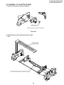
4-21 ASSEMBLING OF PHASE MATCHING
MECHANISM COMPONENTS
• Replacement (Perform in the numerical order)
1 Remove the motor as stated in 4-19 D.D. motor replacement.
2 Remove the drum earth brush ass’y 2.
3 Remove the upper and lower drum assembly from main
chassis 1. 4. Remove the drum FFC holder 3.
• Assemble the phase matching mechanism components in the following order.
1. Assemble the reverse guide lever and pinch drive cam.
2. Mounting the shifter (on the back of the mechanism
chassis).
3. Mounting the master cam (on the back of the mechanism chassis).
4. Assemble the loading motor parts.
[Cares when replacing the drum]
1. Be careful so that the drum earth brush is not lost.
2. Do not touch directly the drum surface.
3. Fit gently the screwdriver to the screws.
4. Since the drum assembly is an extremely precise assembly, it must be handled with utmost care.
5. Make sure that the drum surface is free from dust, dirt
and foreign substances.
6. After replacing the drum be sure to perform the tape
running adjustment.
After that, perform also the electrical adjustment.
• Playback switching point adjustment
• X-position adjustment and check
• Standard and x-3 slow tracking adjustment
7. After replacing the drum clean the drum.
• PINCH DRIVE CAM AND REVERSE GUIDE
LEVER ASSEMBLING METHOD.
(Place the following parts in position in numerical order.)
(1)Pinch drive cam
(2)Reverse guide spring 2
(3)Reverse guide lever ass’y 3
(4)Open guide
4
Insert it into the
groove of the shaft
3
2
2
1
Don't run up
on the spring
1
Dot A
3
Dot B
Figure 4-35.
Lower dorum bottom side
Figure 4-34.
26
VC-A560U(A)/A560U/A560U(B)
VC-H960U/H960U(B)/H961U
1. Make sure that the loading arm T and S are at the PhaseMatching point as shown below a .
2. Fix the shifter position setting part to the roading arm T
position setting part as shown in figure .b
3. Make sure tension arm not run on the shifter as shown
in figure c .
4-22 INSTALLING THE SHIFTER
Drum
Capstan D.D.
motor
Limiter
pully
(Bottom side of mechanism chassis)
Figure 4-36.
Loading arm (T)
Loading arm (S)
Insert point
Loading arm (T)
Phase matting
Shifter
*Not run on the
sifter.
Sifter
Tension arm
Figure 4-37.
27
VC-A560U(A)/A560U/A560U(B)
VC-H960U/H960U(B)/H961U
4-23 INSTALLING THE MASTER CAM (AT
REAR SIDE OF MECHANISM CHASSIS)
4-24 REPLACEMENT OF LOADING MOTOR
• Removal
1. Make sure beforehand that the shifter is at initial position.
2. Place the master cam in the position as shown below.
E-ring
Apply grease
*Apply grease to
the tip as well.
Worm gear
Apply grease
Loading
motor.
Leading connect gear.
Apply grease
Worm wheel gear.
Red
Apply grease
Wire
+ : Red
- : White
Insert
Figure 4-38-1.
L-M-Block.
Note:
See the figure below for the phase matching between the
master cam synchro gear and pinch drive cam.
3. Finally fix with the E ring.
Synchro gear
Phase
matching
Figure 4-39.
Master cam
• Replacement
Remove the loading motor, and install the replacement
loading motor as shown below.
Hole of Pinch
drive cam.
Phase
matching
Worm gear
6.95 +0
-0.15 mm
Line of synchro gear.
Loading
motor
Figure 4-38-2.
A part
To press the motor in, first
receive it by portion A.
Figure 4-40.
The loading motor pressing-in must be less than 14.7 N
(1,500 gf).
Adjust the distance between motor and pulley to 6.95
+0. 2
–0.15 mm.
28
VC-A560U(A)/A560U/A560U(B)
VC-H960U/H960U(B)/H961U
4-25 ASSEMBLY OF CASSETTE HOUSING
1. Proof lever Proof lever spring and Holder R
MSPRD0215AJFJ
*Proof lever spring fixing direction designated.
Figure 4-41.
2. Frame R, Frame L, Drive Arm R, Drive Arm L, Upper
Plate.
LANGF9661AJFW
Top surface should be free from scratches or soil.
29
VC-A560U(A)/A560U/A560U(B)
VC-H960U/H960U(B)/H961U
5. ELECTRICAL ADJUSTMENT
Notes:
• Before the adjustment:
Electrical adjustments discussed here are often required after replacement of electronic components and mechanical
parts such as video heads.
Check that the mechanism and all electric components are in good working condition prior to the adjustments, otherwise
adjustments cannot be completed.
• Instruments required:
• Color TV monitor
• Audio signal generator
• Blank video cassette tape
• Screwdriver for adjustment
• RF signal generator
• Dual-trace oscilloscope
• AC milli-voltmeter
• Alignment tape (VROEFZHS)
• Color bar generator
TP201~204
Figure 5-1.
30
VC-A560U(A)/A560U/A560U(B)
VC-H960U/H960U(B)/H961U
SERVO CIRCUIT ADJUSTMENT
5-2 ADJUSTMENT OF FV (False Vertical
Sync) OF STILL PICTURE
5-1 ADJUSTMENT OF HEAD SWITCHING
POINT
Measuring
instrument
Color TV monitor
Mode
Playback still
Cassette
Self-recorded tape (SP mode)
(See Note below 2)
Measuring
instrument
Dual-trace oscilloscope
Mode
Playback
Cassette
Alignment tape (VROEFZHS)
Control
Tracking control buttons(+) or (–)
Test point
VIDEO OUT jack to CH2
TP202 (Sig.)~TP203 (GND) to CH1
Specification
No vertical jitter of picture
Control
Call up the test mode (short circuit
between TP801 and TP802 on the
operation PWB). Use the tracking/
channel select (') and (") buttons
of the set.
Specification
6.0 ± 0.5H (lines)
1. Play a cassette which was recorded by the unit in SP
mode.
2. Press the PAUSE/STILL button to freeze the picture.
3. Look at the monitor screen and adjust (+) or (–) TRACKING buttons so that the vertical jitter of the picture is
minimized.
4. Play and freeze the self-recorded tape in EP mode and
make sure vertical jitter of the picture is not noticeable.
Note:
1 The FV goes back to the it’s initial state when the unit is
put into the system controller reset mode due to power
failure, etc.
In this case, preset the FV once again.
2 Self-recorded tape is a cassette whose program was
recorded by the unit being adjusted.
1. Connect a dual-trace oscilloscope to the VIDEO OUT
jack and TP202 (Sig.) and TP203 (GND).
(Trigger the oscilloscope with the head switching pulse
on TP202.)
2. Playback the alignment tape, and then short circuit
between TP801 and TP802 on the operation PWB to call
the test mode.
3. Press the PLAY button, and the play LED starts blinking
and the automatic adjustment function gets started.
4. Wait until the play LED stays on to indicate that the
adjustment is complete.
5. Watch the oscilloscope screen and make sure that the
leading edge of the head switching pulse is 6.0H (lines)
ahead of the vertical sync as shown in Figure 5-2.
6. If the setting is out of this range, readjust the data using
the channel select (') and (") buttons of the set or the
remote controller.
7. Finally press the STOP button to quit the test mode.
CH-1: 1V/dev 50µsec/dev
CH-2: 1V/dev 50µsec/dev
CH-2
VIDEO OUT
CH-1
HEAD
SWITCHING
PULSE
5-3 CHECKING OF OFF TRACK
6.0 ± 0.5H (lines)
Measuring
instrument
Color TV monitor
Mode
Playback
Cassette
Self-recorded tape (EP mode)
(See Note below)
Control
Tracking control buttons(+) or (–)
Specification
No Poor picture and Hi-Fi sound
1. Play a cassette which was recorded by the unit in EP
mode.
2. Short circuit between TP801 and TP803 on the main
PWB, and press both CH button (+) and CH button (–) at
same time.
3. Press the tracking buttons (+) or (–) 20 times each to
bring the tracking off center. Make sure that:
1) There is nothing unusual on the playback screen.
2) There is nothing unusual in the Hi-Fi sound (for the HiFi models only).
4. Cancel the short circuit.
Note:
Self-recorded tape is a cassette whose program was recorded by the unit being adjusted.
V-sync.
Figure 5-2.
31
32
0
19.812
CA/END
CS/EJ
1 1
1 1
Mode detection inside
S sensor
Open
S sensor Close
0 0
EJ
10.354 12.812
0
5
10
15
20
25
Mode detection outside
Mode detection inside
(D708 SW A)
Mode detection outside
(D709 SW B)
Mode check
Cam mark
G mechanical timing
0
0
0
UL
0
1
1
1
0
0
0
0
0
0
PU1
PU2
VSR
PB
SLOW
FF
STOP
0
1
1
0
1
1
1
1
0
sensor B
1 1
1
Mode detection outside
0
1 1
PU
PU1
179
180
sensor A
1
1
120
Mode detection inside
0 1
1 1
ULD
1 or 0
0
0
UL
81
CS/EJ
1
0
0
60
Cam graph E
0 0
1 0
PU2
PU2
200
240
0 0 0
1 1 0
VSR
VSR
233
0
1
0
0
PB
PB
265
0
0
0
1
SLW
300
0
1
SLOW
282
0 0
0 1
FF
FF
316
0
1
0
0
STP
STOP
334
380
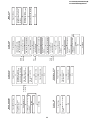
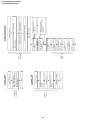
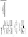
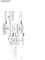
Fullloading
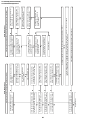
Cassette
inserting
Insert cassette.
Loading motor turns in reverse
direction and master cam
counterclockwise.
Start sensor close.
(Cassette is judged
caught halfway.)
NO
End
End
YES
Is drum FG pulse outputted ?
Loading motor stop.
Cam switch is at PB position.
Pinch roller comes into contact.
Tape loading.
Drum motor starts.
YES
NO
Unloading
Are start/end sensors at low level NO
before cassette insertion ?
(Cassette LED or some other part
is judged defective.)
YES
Does mechanism position sw.
come off within 2.5 sec.?
Loading motor starts in normal
direction and master cam counter
clockwise.
STOP
Cassette is ejected and loading
motor stops.
CASSETTE INSERTION
Double action rack slides.
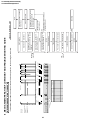
* This flowchart describes the outline of the mechanism’s operation, but does not give its details.
MECHANISM OPERATION FLOWCHART
6. MECHANISM OPERATION FLOWCHART AND TROUBLESHOOTING GUIDE
VC-A560U(A)/A560U/A560U(B)
VC-H960U/H960U(B)/H961U
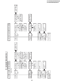
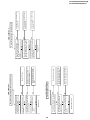
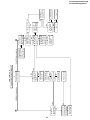
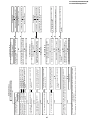
REC/PLAY
33
VSF
End
Set capstan motor to search
speed.
Press FF key.
PLAY
Unloading
End
YES
Is take-up reel sensor signal
outputted ?
Picture appears.
Capstan motor turns
counterclockwise.
Press REC/PLAY key.
STOP
NO
Slow brake
pressing
STILL
STOP
Unloading
End
YES
Is take-up reel sensor signal
outputted ?
End
Stop loading motor.
Cam switch is at VSR
position.
Press pinch roller.
Turn loading motor
counterclockwise.
Cam switch is at PU1 position.
Release the supply auxiliary
brake.
Loading motor turns clockwise.
Turn capstan motor in
reverse direction.
Stop loading motor.
Cam switch is at PU2 position.
Release pinch roller.
Loading motor turns
clockwise and master
cam counterclockwise.
Set capstan motor to search
speed.
Pinch
roller
pressing
Idler
swinging
Pinch
roller
releasing
VSR
Press REW key.
PLAY
Stop capstan motor.
Capstan motor turns in
reverse direction.
Press STOP key.
REC/PLAY
End
Capstan motor stops.
Loading motor stops.
Cam switch is at STILL
position.
Slow brake comes into
contact with capstan motor.
Loading motor turns in
counterclockwise direction
and master cam clockwise.
Press STILL key.
PLAY
NO
PLAY
End
Cam switch is at PB position.
Capstan motor turns
counterclockwise. PB speed.
Loading motor turns counterclockwise and master cam
clockwise.
Press PLAY Key.
VSR
VC-A560U(A)/A560U/A560U(B)
VC-H960U/H960U(B)/H961U
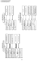
Brake
function
FF/REW
operation
FF/REW
STOP
34
End
Loading motor stops.
Cam switch is at Stop
position.
Stop capstan motor.
Loading motor turns counterclockwise.
Press STOP key.
FF/REW
End
Turn capstan motor in
normal or reverse direction,
after the remaining tape has
been detected.
Press FF/REW key.
STOP
Cassette
eject
Tape
unloading
CASSETTE EJECT
End
Capstan motor
stops.
Loading motor
stops.
Cam switch is at
Eject position.
Loading motor turns
clockwise.
Capstan motor turns
clockwise.
YES
Does the take-up
reel pulse output
two edges ?
YES
4 supply reel pulses
outputted ?
NO
NO
Capstan motor turns
counterclockwise in about
2 seconds.
Capstan motor turns
clockwise.
Stop loading motor.
Cam switch is at UL position.
Capstan motor turns in reverse direction.
Loading motor turns in clockwise and master cam
counterclockwise.
Press EJECT key.
STOP
VC-A560U(A)/A560U/A560U(B)
VC-H960U/H960U(B)/H961U
NO
35
The cassette tape
is presumably
damaged.
YES
Is the pulse
NO
outputted from reel
sensor ?
YES
Are idler wheel
NO
ass’y and reel disk
in mesh ?
YES
Does capstan
NO
motor turn in FF (or
REW) direction ?
YES
Is master cam at
FF position ?
Replace the reel
sensor.
Replace the idler
ass’y.
Replace the
capstan motor.
YES
Are Vco 12V and
Vcc 5V applied ?
Loading motor
control system
in trouble.
YES
Modes changing
smoothly through
cam switch ?
YES
Does loading
motor operate ?
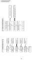
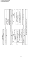
Press FF key.
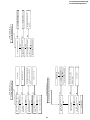
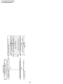
1. FF/REW FAILURE (NO TAPE WINDING)
NO
NO
NO
Voltage supply
system in trouble.
Mode sensor
system in trouble
or master cam
malpositioned.
Loading motor is
damaged. Replace
it.
YES
Is voltage applied NO
to loading motor ?
MECHANISM TROUBLESHOOTING
Voltage supply
system in trouble.
NO
Check main PWB.
YES
Is the pulse
NO
outputted from reel
sensor ?
YES
Are idler wheel
NO
ass'y and reel disk
in mesh ?
YES
Does capstan
motor turn ?
YES
Is the master cam NO
at PB position ?
Replace the reel
sensor.
Replace the idler
ass’y.
Replace the
capstan motor.
YES
Are Vco 12V and
Vcc 5V applied ?
Loading motor
control system
in trouble.
YES
Modes changing
smoothly through
cam switch ?
YES
Does loading
motor operate ?
2. REC/PLAY FAILURE (MODE RELEASE)
NO
NO
Voltage supply
system in trouble.
Loading motor is
damaged. Replace
it.
YES
Is voltage applied NO
to loading motor ?
Voltage supply
system in trouble.
VC-A560U(A)/A560U/A560U(B)
VC-H960U/H960U(B)/H961U
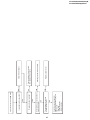
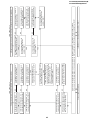
NO
NO
36
Check main PWB.
YES
Is pulse outputted NO
from reel sensor ?
YES
Is supply reel disk NO
winding torque
normal ?
YES
Are idler wheel
NO
ass’y and supply
reel disk in mesh ?
YES
Master cam
shifting to VSR
position ?
Press REW key.
YES
Is Playback
function normal ?
Replace reel
sensor.
Replace limiter
pulley ass’y.
Replace idler
gear ass’y.
Go to 2. REC/
PLAY FAILURE
routine.
Go to 2. REC/
PLAY FAILURE
routine.
3. WINDING FAILURE AT VSR
Replace loading motor block.
YES
Is unusual sound heard during
loading/unloading ?
NO
Unusual sound heard with pinch
roller lever going up or down ?
NO
Is unusal sound heard during
cassette control running ?
4-i) Unusual sound in cassette
insertion and ejection mode
YES
YES
4. UNUSUAL SOUND IN EACH MODE
Check pinch roller drive cam, pinch roller
drive lever and reverse guide for their actions.
Replace damaged one with new one.
Replace cassette control ass’y.
VC-A560U(A)/A560U/A560U(B)
VC-H960U/H960U(B)/H961U
37
Check drive system’s gears for
damage. Replace damaged gear
with new one.
• Reel disk
• Limiter pulley ass’y
• Idler wheel ass’y
NO
Turn capstan motor by hand.
Unusual sound heard ?
NO
Drive system out of contact with any
part on main PWB ?
YES
Thrust gap found at reel disk ?
YES
Is reel disk height as specified ?
4-ii) Unusual sound in FF/REW mode
YES
YES
NO
NO
Replace capstan motor.
Rearrange the parts on main PWB.
Check reel disk and main chassis.
And replace defective parts.
Adjust reel disk height.
VC-A560U(A)/A560U/A560U(B)
VC-H960U/H960U(B)/H961U
38
Replace IC901.
Check whether the secondary side
photocoupler circuit operates
normally.
YES
Check whether the primary side
photocoupler output control
functions normally.
YES
Check the circuit and replace parts.
(IC901, IC903, etc.)
Check the circuit and replace parts.
(IC901, IC903, Q902, T901, etc.)
NO
NO
When the output voltage fluctuates.
FLOW CHART NO.3
Check for short-circuiting of
rectifying diode and circuit in each
rectifying circuit of secondary circuit.
(D9334, D931~933)
Check for leak or short-circuiting of
primary circuit part.
(L901, D901~904, T901, C906,
R904, Q901~902, etc.)
Check the power failure circuit.
(Q705)
Check each rectifier circuits and
short-circuit of secondary circuit.
Check for leak or short-circuiting
of primary circuit part.
(L901, D901~904, T901, C906,
R904, Q901~902, etc.)
Case (2)
Fuse blown out.
FLOW CHART NO.2
NO
NO
NO
NO
Case (1)
Is "H" level applied at pin(96) of
IC701?
YES
Are AT 44V, AT 27V, PC 12V,
normal?
YES
Are AT 5V voltage line normal?
YES
Is the normal state restored when
once unplugged power cord is
plugged again after several
seconds?
YES
Is the fuse good?
The fuse blows out even when it is
replaced with new one.
See FLOW CHART NO.2
<Fuse blown out.>.
Check for short-circuiting of circuit and rectifying diode of each rectifying circuit of secondary
circuit and check for failure of shunt regulator circuit. (D9334, D931~933, IC903, C935, C963)
When buzz is heard from the vicinity of power circuit.
No power
NO
FLOW CHART NO.4
FLOW CHART NO.1
7. TROUBLESHOOTING
VC-A560U(A)/A560U/A560U(B)
VC-H960U/H960U(B)/H961U
FLOW CHART NO.6
39
YES
Replace loading motor.
YES
Does pin(10) of P701 go from 2.5V
to 4.2V when the cassette tape is
inserted.
NO
NO
NO
Check line pin(72) of IC701 and all
the way up thru to pin(10) of P701.
Check line start sensor and all the
way up thru to pin(67) of IC701.
Check start sensor shutter.
Check line between at remote
control receiver thru to pin(4) of
IC701.
A cassette tape is not take in.
Does pin(67) of IC701 change from
"H" to "L" level when the cassette
tape is inserted?
YES
NO
Check AT 5V lines.
Replace the remote control receiver
or replace the remote control
transmitter if necessary.
FLOW CHART NO.7
Are start sensor shutter go to open
when the cassette tape is inserted?
Replace IC701.
YES
Is inputted "L" pulse to pin(4) of
IC701?
YES
Is "L" pulse sent out pin(1) terminal of
NO
receiver when the infrared remote
control is activated?
Operation is possible from the VCR,
but no operation is possible from the
infrared remote control.
YES
Is the supply voltage of 5V feed to
NO
pin(3) terminal of remote control
receiver?
YES
No operation is possible from the infrared remote control.
NO
Replace IC701.
YES
Does the master cam mode shifter
operate normally when the cassette
tape is loaded?
YES
NO
Does the end sensor pulse at pin(66) NO
of IC701 change from "L" to "H" level
when the cassette tape is loaded?
YES
Does the start sensor pulse at
pin(67) of IC701 change from "L" to
"H" level when the cassette tape is
loaded?
Check cam switch and all the way
up thru to IC701.
Check end sensor and all the way
up thru to IC701.
Check start sensor and all the way
up thru to IC701.
A cassette tape is taken in, but ejected at once.
FLOW CHART NO.8
VC-A560U(A)/A560U/A560U(B)
VC-H960U/H960U(B)/H961U
Replace cassette cam, gear, etc.
YES
Does the loading motor run?
YES
Does pin(10) of P701 go from 2.5V
to 0.8V when veel pules has beer
input.
YES
Are pulses applied at pin(2) of IC701
when the take-up reel disk is turning?
YES
NO
NO
NO
Does the take-up reel disk turn when NO
the capstan motor is running?
YES
NO
Replace loading motor.
Check pin(72) of IC701.
Check take-up reel sensor and all the
way up thru to IC701.
Check reel disk and reel drive unit.
See FLOW CHART NO.11.
NO
NO
40
NO
Is the voltage more than 2.6V DC
sent in pin(9) of P701.
Is the supply voltage of 12V feed to
pin(2) of P701.
YES
Is the voltage at pin(5) of P701
3.5V?
YES
YES
YES
NO
NO
NO
Is the supply voltage of 5V feed to
pin(3) of P701.
YES
NO
Replace capstan motor.
Check motor-VCC line and motor
voltage selector circuit.
Check between the pin(71) of IC701
and all the way up thru to pin(5) of
P701.
Check between pin(9) of P701 and
all the way up thru to pin(24) of
IC701.
Check PC 5V line.
Check IC701.
Check Q951 and the AT 5V line.
The capstan motor fails to run.
Is the voltage more than about 2.6V
DC given out of pin(24) of IC701.
Check IC701.
Check IC701 and all the way up thru
to Q951.
FLOW CHART NO.11
Check peripheral circuits for poor
soldering.
YES
Is 5V sent out of the emitter of
Q951?
YES
Does the base of Q951 change from NO
about 5.0V to 4.5V?
YES
Does power control(H) signal at
pin(76) of IC701 change from "L" to
"H" level?
No power is turned on.
The cassette tape fails to eject.
Does the capstan motor start when
the EJECT button is pressed?
FLOW CHART NO.10
FLOW CHART NO.9
VC-A560U(A)/A560U/A560U(B)
VC-H960U/H960U(B)/H961U
41
FLOW CHART NO.13
NO
NO
NO
Check AT 12V line.
Check between pin(25) of IC701
and all the way up to pin(12) of
P701.
Check PC 5V line.
Check IC701.
Replace IC701.
YES
Is V-H.SW.P pulse given out of
pin(18) of IC701?
YES
Is drum PG signal given out of
pin(47) of IC701?
YES
Is drum PG signal given out of
pin(11) of P701.
NO
NO
NO
Check IC701.
Check line between pin(11) of P701
and all the way up thru to
pin(47) of IC701.
Check or replace drum motor.
YES
Check pin(12) of P701.
NO
Replace IC706.
The drum motor runs only for a few seconds.
Check or replace drum motor.
YES
Is the supply voltage of 12V feed to
pin(8) of P701.
YES
Is the voltage more than about 2.6V
applied at pin(2) of P701.
YES
Is the supply voltage of 5V feed to
pin(3) of P701.
YES
NO
NO
Check peripheral circuit of P701
Is the drum PG/FG signal present
on pin(11) of P701.
YES
Is the drum PG/FG signal present
on pin(47) of IC701.
YES
Is the drum motor rotating?
YES
NO
NO
Replace IC701.
See FLOW CHART NO.12,13
Could be lines between P701
and IC701.
No head switching pulse.
The drum motor fails to run.
Is the voltage more than about 2.6V
DC given out of pin(25) of IC701.
FLOW CHART NO.14
FLOW CHART NO.12
VC-A560U(A)/A560U/A560U(B)
VC-H960U/H960U(B)/H961U
Check drum PG/FG signal line.
YES
42
Does the IC706 operate normally?
YES
Is the drum control voltage applied
to pin(2) of IC701.
YES
Is the drum-error at pin(29) of IC701
present?
YES
YES
NO
NO
Is the head switching pulse at pin(18) NO
of IC701 present?
NO
Is there drum PG/FG signal at
pin(47).
In PB mode
Replace drum motor.
Is pin(25) of IC701 in high
impedance?
YES
Check lines between pin(29) of
IC701 and pin(12) of P701.
Replace IC701.
See FLOW CHART NO.14.
YES
Is there 14.318MHz oscillation at
pins(37) and (38) of IC701?
Drum servo does not function.
FLOW CHART NO.15
NO
NO
YES
Replace IC701.
Check peripheral circuit of pin(41) of
IC701, C715, C7716 and R708.
NO
Is the V-SYNC signal(reference) at
pin(41) of IC701?
In REC mode
Check peripheral circuit of X701.
VC-A560U(A)/A560U/A560U(B)
VC-H960U/H960U(B)/H961U
43
YES
Adjust the height
of the A/C head.
YES
Does A/C head
NO
operate normally?
NO
Does PB CTL
signal appear at
pin(58) of IC701?
1
Only PB mode inoperative
Replace A/C head.
Replace IC701.
NO
Is there CAPERROR at pin(28)
of IC701?
YES
Check capstan
motor unit and/or
replace.
Check peripheral
circuit of X701.
NO
Is there 14.318MHz YES
oscillation at pin
(32) and (33) of
IC701?
YES
Are REC and/or PB
mode inoperative?
Capstan servo does not function.
FLOW CHART NO.16
Check peripheral
circuit of pin(41) of
IC701, C715,
C7716 and R708.
Only REC mode inoperative
Check peripheral
circuit of AC
connector.
NO
YES
Is there REC CTL
NO
signal output at
pin(57) and (56)
of IC701?
YES
Does the capstan
FG signal appear YES
at pin (49) of IC701?
NO
Check the capstan
FG signal line between pin(1) of
P701 and pin(49)
of IC701.
NO Is the V-SYNC
signal(reference) at
pin(41) of IC701?
2
Check "1"
YES
Does pin(24) of
IC701 operate
normally?
YES
Is there CAPERROR signal at
pin (28) of IC701?
NO
Replace IC701.
NO
NO
Check "2"
Replace IC701.
YES Does PB CTL
signal appear at
pin (58) of IC701?
NO
VC-A560U(A)/A560U/A560U(B)
VC-H960U/H960U(B)/H961U
FLOW CHART NO.17
Check the line between pin(52) of IC201
and pin(40) of IC701.
NO
44
Check the AT 5V line.
NO
Is 5V applied to the pin(42) of IC701?
NO
NO
Check the PC 5V line.
NO
Check Q251 periphery.
Check the line between pins(63) and (62) of
IC201 and pins(64) and (65) of IC701.
NO
Is serial data clock signal applied to the
pins(63) and (62) of IC201?
YES
Is 5V applied to the pins(12), (61) and (90) of IC201?
NO
1 External input mode
Check the line between the rear video input terminal
and pin(30) of IC201.
2 U/V tuner mode
Check the line between the pin(25) of U/V tuner and
pin(31) of IC201.
1 Line output: Check Q251 periphery and output terminal periphery.
2 RF output: Check Q251 periphery and tuner pin(6) periphery.
YES
Is picture signal output to the emitter of video output
buffer (Q251)?
YES
Is picture signal output to the pin(38) of IC701 ?
YES
NO
Is picture signal output to the pin(52) of IC201?
Is picture signal input into the pin(40) of IC701?
YES
YES
Is picture signal input into pins(30) and (31) of IC201?
Picture E-E does not appear.
VC-A560U(A)/A560U/A560U(B)
VC-H960U/H960U(B)/H961U
45
YES
Check the pins(13) and (14) of IC201
peripheral circuit. (R201, R202, C203)
Check between the pins(24) and
(23) of IC201. (Check C210.)
Is CCD control voltage approx. 5V
applied normally to the pin(37) from
the pin(57) of IC201? Is clock signal
(approx. 7.16 MHz/0.5 Vp-p) for
CCD applied normally to the pin(44)
from the pin(69) of IC201?
YES
Is voltage 5V applied to the CCD section
power terminal pin(36) of IC201?
NO
Is luminance signal (approx. 0.5
Vp-p) input to the pin(39) of IC201?
YES
Check between the pins(39) and
(26) of IC201. (Check C212.)
Check between the pins(21) and
(42) of IC201. (Check C208.)
Check between the pins(18) and
(19) of IC201. (Check C206.)
YES
Is chroma signal (approx. 180
mVp-p/Burst) input into the
pin(58) of IC201?
YES
Is chroma signal (approx. 143
mVp-p/Burst) input into the
pin(46) of IC201?
YES
Is voltage 5V applied to the chroma
power terminal pin(61) of IC201?
NO
NO
NO
NO
Is chroma signal (approx. 180
mVp-p/Burst) output to the
pin(35) of IC201?
YES
Is PRE/REC Vcc 5V applied to the pin(90) of IC201?
NO
YES
Check between the pins(58) and
(35) of IC201. (Check R505, C512.)
Check whether the pins(71) and
(73) of IC201 oscillate (3.58 MHz)?
YES
Check between the pins(60) and
(46) of IC201. (Check C512.)
Check the periphery of pin(61) of
IC201 and PC 5V line.
SP mode: Is record FM signal (approx. 20 mAp-p) output to the pins(88) and (89) (SP1) and pins(86) and (87) (SP2) of IC201?
EP mode: Is record FM signal (approx. 20 mAp-p) output to the IC201 pins(93) and (94) (EP1) and pins(92) and (91) (EP2) of IC201?
NO
NO
NO
NO
NO
Check or replace the cylinder.
Is the luminance signal (approx. 0.5
Vp-p) input and output to the pins(13)
and (14) of IC201, respectively?
YES
Is luminance signal (approx. 0.5
Vp-p) input to the pin(23) of IC201?
YES
Is luminance signal (approx. 0.5
Vp-p) input to the pin(26) of IC201?
YES
Is luminance signal (approx. 0.3
Vp-p) input to the pin(42) of IC201?
YES
Is luminance signal (approx. 0.5
Vp-p) input to the pin(19) of IC201?
FLOW CHART NO.19
Although picture record is possible, color does not appear (E-E mode is possible).
FLOW CHART NO.18
Picture (luminance) record is impossible (E-E mode is possible).
VC-A560U(A)/A560U/A560U(B)
VC-H960U/H960U(B)/H961U
46
NO
NO
Replace IC201.
YES
Is luminance signal (approx. 0.5
Vp-p) input to the pin(23) of IC201?
YES
NO
NO
Is luminance signal (approx. 0.5
Vp-p) input to the pin(26) of IC201?
YES
Is luminance signal (approx. 0.5
Vp-p) input to the pin(42) of IC201?
YES
Is luminance signal (approx. 0.5
Vp-p) input to the pin(19) of IC201?
YES
Is the luminance signal (approx. 0.25
NO
Vp-p) input and output to the pins(13),
(14) and (16) of IC201, respectively?
YES
NO
YES
NO
NO
NO
YES
NO
Is chroma signal (approx. 508
mVp-p/Burst) output to the
pin(35) of IC201?
YES
Check between the pin(58) and pin(35)
of IC201. (Check R505, C515.)
Check whether the pin(71) and pin(73)
of IC201 oscillate (3.58 MHz)?
YES
Check between the pin(60) and
pin(46) of IC201. (Check C512.)
Check the periphery of pin(61) of
IC201 and PC 5V line.
Is voltage 5V applied to the CCD section power terminal pin(36) of IC201?
Replace IC201.
Check between the pin(55) and
pin(54) of IC201. (Check C514.)
NO
Is chroma signal (approx. 286
mVp-p/Burst) input into the
pin(54) of IC201?
YES
Is chroma signal (approx. 508
mVp-p/Burst) input into the
pin(58) of IC201?
YES
Is chroma signal (approx. 403
mVp-p/Burst) input into the
pin(46) of IC201?
YES
Is voltage 5V applied to the chroma
power terminal pin(61) of IC201?
Check between the pins(24) and (23) of IC201. (Check C210.)
Is control voltage approx. 5V applied normally to the pin(37) from the pin(57) of IC201? Is CCD clock signal
(approx. 7.16 MHz/0.5 Vp-p) applied to the pin(44) from the pin(69) of IC201?
NO
Is luminance signal (approx. 0.5
Vp-p) input to the pin(39) of IC201?
YES
Check between the pin(39) and
pin(26) of IC201. (Check C212.)
Check between the pin(21) and
pin(42) of IC201. (Check C208.)
Check between the pin(18) and
pin(19) of IC201. (Check C206.)
Check the periphery of pins(13),
(14) and (16) of IC201. (Check
C203, R201-2, L201, C205, R203.)
Check V-H.SW.P. line.
NO
Is V-H.SW.P. applied to the
pin(81) of IC201?
NO
Is luminance signal (approx. 0.4
Vp-p) input to the pin(79) of IC201?
YES
Check between the pins(79) and
(78) of IC201.
Although picture is played back, color does not appear (E-E mode is possible).
Playback picture does not appear (E-E mode is possible).
Is FM signal (approx. 0.4 Vp-p)
input to the pin(78) of IC201?
FLOW CHART NO.21
FLOW CHART NO.20
VC-A560U(A)/A560U/A560U(B)
VC-H960U/H960U(B)/H961U
pin(14) pin(9)
pin(48)
Rear input terminal
Tuner audio terminal
47
NO
NO
NO
NO
NO
NO
NO
Check line between X501 and pin(45)
of IC651.
NO
Is Sub carrier signal (3.58MHz, about
900mVp-p) input to pin(45) of IC651?
Check line between pin(36) of IC651
and pin(61) of IC701.
Check line between pins(43), (42) of
IC651 and pins(12), (13) of IC701.
Check the regulator circuit of Hi-Fi 5V
and PC 9V.
Check the peripheral circuit of front
input terminal.
Check the peripheral circuit of rear
input terminal.
Is there SIF signal from pin(24) of
Tuner?
Replace IC651.
NO
Line output terminal : Check line ranging from pins(53) and (57) of IC651 to the audio
output terminal.
RF output terminal : Check line ranging from pin(59) of IC651 to pin(2) of tuner (TU101).
YES
Line output terminal : Is there audio signal outputted at pins(53) and (57) of IC651?
RF output terminal : Is there audio signal outputted at pin(59) of IC651?
YES
Is "H" level applied at pin(45) of IC651?
YES
Is "L" level applied at pin(36) of IC651?
YES
Are serial data and clock signal at
pins(43), (42) of IC651?
YES
Is the voltage 5V applied to pin(40) of
IC651, 9V applied to pin(58).
YES
pin(15) pin(10)
Front input terminal
Is there signal inputted at each
terminal of IC651 as shown in table?
L-ch R-ch
No Hi-Fi E-E sound heard.
FLOW CHART NO.22
Check the AA-MH harness and A/C head.
YES
Is audio signal on which bias signal is
superposed output to the pin(4) of IC201?
YES
Does the bias oscillation circuit operate
normally?
YES
Is the pin(99) of IC201 in "L" level?
YES
Is audio signal input into the IC201 pin(8)?
Recording in linear audio is impossible
(Hi-Fi E-E mode is normal).
FLOW CHART NO.25
Replace IC651.
YES
Is playback envelope signal output to the
pins(29) and (30) of IC651? (300 mVp-p)
Hi-Fi sound cannot be played back
(E-E mode is normal).
FLOW CHART NO.24
Check the AH-MZ connector.
YES
Is record FM signal output to the pins(21) to
(24) (ch-1)/pins(21) and (22) (ch-2) of IC651?
YES
Is terminal voltage (REC AGC. ADJ.) pin(37)
of IC651 normal?
FLOW CHART NO.23
Hi-Fi sound cannot be recorded
(E-E mode is normal).
NO
NO
NO
NO
NO
NO
Check the bias oscillation circuit (T601, Q602,
Q603).
Check the periphery of pin(99) of IC201.
Check the line between the pin(61) of IC651
to the pin(8) of IC201.
Check the A-H.SW.P. line from the pin(27) of
IC651 to the pin(23) of IC701.
NO
Is A-H.SW.P input into the pin(27) of IC651?
YES
Replace IC651.
Check line of Hi-Fi 5V.
NO
Is voltage 5V applied to pin(25) of IC651.
Check Hi-Fi REC CTL line.
NO
Is the pin(29) of IC651 about 3.7V?
YES
Replace IC651.
VC-A560U(A)/A560U/A560U(B)
VC-H960U/H960U(B)/H961U
FLOW CHART NO.26
Check the line between the pin(11) of IC201 to
the pin(62) of IC651.
YES
Is audio signal output to the pin(11) of IC201?
YES
Is it possible to confirm the audio signal (PB EQ)
on the pin(100) of IC201?
Linear audio playback is impossible.
(Hi-Fi E-E mode is normal).
NO
NO
NO
Replace IC201.
YES
Check the periphery of pin(99) of IC201.
NO
Is the pin(99) of IC201 in "L" level?
Readjust the A/C head height.
Replace the AC head.
YES
Is AC head height adjusted properly?
YES
Is the AC head surface clean?
YES
Are MH-AA harness and playback AMP.
peripheral parts normal?
VC-A560U(A)/A560U/A560U(B)
VC-H960U/H960U(B)/H961U
48
VC-A560U(A)/A560U/A560U(B)
VC-H960U/H960U(B)/H961U
-MEMO-
49
VC-A560U(A)/A560U/A560U(B)
VC-H960U/H960U(B)/H961U
VC-A560U(A)/A560U/A560U(B)
VC-H960U/H960U(B)/H961U
8. BLOCK DIAGRAM
SYSTEM SERVO BLOCK DIAGRAM
50~51
VC-A560U(A)/A560U/A560U(B)
VC-H960U/H960U(B)/H961U
VC-A560U(A)/A560U/A560U(B)
VC-H960U/H960U(B)/H961U
SIGNAL FLOW BLOCK DIAGRAM(VC-A560U(A)/A560U/A560U(B))
52~53
VC-A560U(A)/A560U/A560U(B)
VC-H960U/H960U(B)/H961U
VC-A560U(A)/A560U/A560U(B)
VC-H960U/H960U(B)/H961U
SIGNAL FLOW BLOCK DIAGRAM(VC-H960U/H960U(B)/H961U)
54~55
VC-A560U(A)/A560U/A560U(B)
VC-H960U/H960U(B)/H961U
POWER CIRCUIT BLOCK DIAGRAM
56
VC-A560U(A)/A560U/A560U(B)
VC-H960U/H960U(B)/H961U
SCHEMATIC DIAGRAM
• The indicated voltages in the following diagram
are measured with an SSVM, upon receiving
color bars (400 Hz sound signal) in either the
record mode or the play mode voltage is indicated as follows.
4.0 . . . . Record mode (SP)
(4.0) . . . . PB mode (SP)
4.0 . . . . LP mode
4.0 . . . . EP mode
IMPORTANT SAFETY NOTICE:
PARTS MARKED WITH " å" (
) ARE
IMPORTANT FOR MAINTAINING THE SAFETY
OF THE SET.
BE SURE TO REPLACE THESE PARTS WITH
SPECIFIED ONES FOR MAINTAINING THE SAFETY AND PERFORMANCE OF THE SET.
NOTE:
1. The unit of resistance "ohm" is omitted (K: 1000
ohms M: 1 Meg ohm).
2. All resistors are 1/8 watt, unless otherwise noted.
3. All capacitors µF, unless otherwise noted P: µµF.
AVIS DE SECURITE IMPORTANT:
LES PIECES MARQUEES " å" (
) SONT
IMPORTANTES POUR MAINTENIR LA SECURITE
DE L'APPAREIL.
NE REMPLACER CES PIECES QUE PAR DES
PIECES DONT LE NUMERO EST SPECIFIE POUR
MAINTENIR LA SECURITE ET PROTEGER LE
BON FONCTIONNEMENT DE L'APPAREIL.
Voltages and waveform are measured as follows:
• DC voltages are measured with an SSVM placed
between points indicated and chassis ground,
with the supply voltage of 120V AC and all
controls for normal positions.
This circuit diagram is a standard one, actual circuits
printed may be subject to change for product
improvement without prior notice.
57
VC-A560U(A)/A560U/A560U(B)
VC-H960U/H960U(B)/H961U
VC-A560U(A)/A560U/A560U(B)
VC-H960U/H960U(B)/H961U
9. SCHEMATIC DIAGRAM AND PWB FOIL PATTERN
MAIN CIRCUIT(1)
J
I
H
G
F
E
D
C
B
A
1
2
* VOLTAGE MEASUREMENT MODE
PB .......... Parentheses ( )
REC ....... Without Parentheses
3
4
5
6
7
8
9
10
11
58~59
12
13
14
15
16
17
18
19
20
VC-A560U(A)/A560U/A560U(B)
VC-H960U/H960U(B)/H961U
VC-A560U(A)/A560U/A560U(B)
VC-H960U/H960U(B)/H961U
MAIN CIRCUIT(2)
J
I
H
G
F
E
D
C
B
A
1
2
* VOLTAGE MEASUREMENT MODE
PB .......... Parentheses ( )
REC ....... Without Parentheses
3
4
5
6
7
8
9
10
11
60~61
12
13
14
15
16
17
18
19
20
VC-A560U(A)/A560U/A560U(B)
VC-H960U/H960U(B)/H961U
VC-A560U(A)/A560U/A560U(B)
VC-H960U/H960U(B)/H961U
MAIN CIRCUIT(3)
J
I
H
G
F
E
D
C
B
A
1
2
* VOLTAGE MEASUREMENT MODE
PB .......... Parentheses ( )
REC ....... Without Parentheses
3
4
5
6
7
8
9
10
11
62~63
12
13
14
15
16
17
18
19
20
VC-A560U(A)/A560U/A560U(B)
VC-H960U/H960U(B)/H961U
VC-A560U(A)/A560U/A560U(B)
VC-H960U/H960U(B)/H961U
MAIN CIRCUIT(4)
J
I
H
G
F
E
D
C
B
A
1
2
* VOLTAGE MEASUREMENT MODE
PB .......... Parentheses ( )
REC ....... Without Parentheses
3
4
5
6
7
8
9
10
11
64~65
12
13
14
15
16
17
18
19
20
VC-A560U(A)/A560U/A560U(B)
VC-H960U/H960U(B)/H961U
OPERATION CIRCUIT
J
I
H
G
F
E
D
C
B
A
1
2
* VOLTAGE MEASUREMENT MODE
PB .......... Parentheses ( )
REC ....... Without Parentheses
3
4
5
6
66
7
8
9
10
VC-A560U(A)/A560U/A560U(B)
VC-H960U/H960U(B)/H961U
PWB FOIL PATTERN
OPERATION PWB
J
I
H
G
F
E
D
C
B
A
1
2
3
4
5
6
67
7
8
9
10
VC-A560U(A)/A560U/A560U(B)
VC-H960U/H960U(B)/H961U
VC-A560U(A)/A560U/A560U(B)
VC-H960U/H960U(B)/H961U
MAIN PWB
J
I
H
G
F
E
D
C
B
A
1
2
3
4
5
6
7
8
9
10
11
68~69
12
13
14
15
16
17
18
19
20
VC-A560U(A)/A560U/A560U(B)
VC-H960U/H960U(B)/H961U
-MEMO-
70
VC-A560U(A)/A560U/A560U(B)
VC-H960U/H960U(B)/H961U
Part No.
★
Description
10. REPLACEMENT
PARTS
LISTCode
Ref. No.
Ref. No.
No.
★
Description
10.PartLISTE
DES
PIECES
Code
PARTS REPLACEMENT
CHANGE DES PIECES
Many electrical and mechanical parts in video cassette recorder have
special safety-related characteristics. These characteristics are often
not evident from visual inspection nor can the protection afforded by
them necessarily be obtained by using replacement components rated
for higher voltage, wattage, etc. Replacement parts which have these
special safety characteristics are identified in this manual; electrical
components having such features are identified by " å " and shaded
areas in the Replacement Parts Lists and Schematic Diagrams.
The use of a substitute replacement part which does not have the same
safety characteristics as the factory recommended replacement parts
shown in this service manual may create shock, fire or other hazards.
De nombreuses pièces électriques et mécaniques de magnétoscopes présentent des caractéristiques particulières de sécurité.
Ces caractéristiques ne sont pas toujours évidentes à l’inspection
visuelle et la protection qu’elles assurent ne peut pas toujours être
obtenue par des pièces de rechange étalonnées à un régime de
tension, une puissance, etc. superieurs. Les pièces de rechange qui
présentent ces caractéristiques spéciales de sécurité, sont identifiées
dans ce manuel: les pièces électriques qui présentent ces particularités,
sont repérée par la marque " å " et sont hachurées dans les listes de
pièces et dans les diagrammes schématiques.
La substitution d’une pièce de rechange par une autre qui ne présente
pas les mêmes caractéristiques de sécurité que la pièce recommandée
par l’usine et repérée dans ce manuel de service, peut provoquer une
électrocution, un incendie ou tout autre sinistre.
"HOW TO ORDER REPLACEMENT PARTS"
To have your order filled promptly and correctly, please furnish
the following informations.
1. MODEL NUMBER
2. REF. NO.
3. PART NO.
4. DESCRIPTION
in USA :
"COMMENT COMMANDER LES PIECES DE RECHANGE"
Pour que votre commande soit rapidement et correctement remplie,
veuillez fournir les renseignements suivants.
Contact your nearest SHARP Parts Distributor to order.
For location of SHARP Parts Distributor,
Please Call Toll-free;
1-800-BE-SHARP
1. NUMERO DU MODELE
3. NO. DE PIECE
2. NO. DE REF
4. DESCRIPTION
In CANADA: Contact Sharp Electronics of Canada Limited
HOW TO IDENTIFY CHIP
TRANSISTORS AND
DIODES BY ITS MARKING
★MARQUE: SECTION LIVRAISON DES PIECES DE RECHANGE
Ref. No.
(3)
Marking
Marking
TR/TS
LE/LF
PC
PD
NC
ND/NE
Description
- Operation Unit
(VC-A560U/A560U(B)/
H960U/H960U(B)/H961U)
DUNTKB106TEW1 - Opeation Unit
(VC-A560U(A))
Fig. 1
Package
Fig. 1
Fig. 1
Fig. 1
Fig. 1
Fig. 1
Fig. 1
★
Part No.
DUNTKB106TEV3
(1) Base/Input
(2) Emitter/Ground
(3) Collector/Output
(1)
(2)
Phone (416) 890-2100
Code
—
—
DUNTKB105TEVA(VC-A560U)
DUNTKB105TEVC(VC-H960U)
DUNTKB105TEVX(VC-H960U(B))
DUNTKB105TEVY(VC-A560U(B))
DUNTKB105TEVZ(VC-H961U)
DUNTKB105TEW1(VC-A560U(A))
MAIN UNIT
Parts No.
VS2SA1530ARS1
VS2AC3052EF-1
VSKRA103S//-1
VSKRA104S//-1
VSKRC103S//-1
VS2SD1306-E1E
TUNER
MARK★: SPARE PARTS-DELIVERY SECTION
Ref. No.
Part No.
★
Description
IC201
VHiHA8317NF-1
IC651
VHiAN3663FB-1
IC701
RH-iXA033WJZZ
IC701
IC710
RH-iXA034WJZZ
VHiBR24C02F1E
IC710
VHiS524CD2S1E
IC903
VHiKiA431//-1
V Tuner
BC
INTEGRATED CIRCUITS
PRINTED WIRING BOARD ASSEMBLY
- Main Unit(VC-A560U)
- Main Unit(VC-H960U)
- Main Unit
(VC-H960U(B))
DUNTKB105TEVY - Main Unit
(VC-A560U(B))
DUNTKB105TEVZ - Main Unit(VC-H961U)
DUNTKB105TEW1 - Main Unit
(VC-A560U(A))
RTUNQ0003AJZZ
Code
PRINTED WIRING BOARD ASSEMBLIES
(NOT REPLACEMENT ITEM)
DUNTKB105TEVA
DUNTKB105TEVC
DUNTKB105TEVX
TU101
—
—
—
—
—
—
71
V HA118317NF,
AZ
Y/C Audio Processor
V AN3663FBP, Hifi Audio
Processor
(VC-H960U/H960U(B)/
H961U)
V IXA033WJ
(VC-A560U(A)/A560U(B)/
H960U(B)/H961U)
V IXA034WJ(VC-A560U/H960U)
V BR24C02F-W E2PROM
AF
(VC-A560U(A))
V S524CD2S E2PROM
(VC-A560U/A560U(B)/
H960U/H960U(B)/H961U)
V KIA431
AE
VC-A560U(A)/A560U/A560U(B)
VC-H960U/H960U(B)/H961U
Ref. No.
Part No.
★
Description
å L934
TRANSISTORS
Q251
Q602
Q603
Q604
Q605
Q606
Q651
VS2SA1530ARS1
VS2SC3203Y/-1
VS2SC3052EF-1
VSKRA103S//-1
VS2SC3052EF-1
VS2SC3052EF-1
VS2SC3052EF-1
V
V
V
V
V
V
V
Q652
VS2SC3052EF-1
V
Q658
Q704
Q705
Q706
Q861
Q862
Q863
Q864
å Q901
å Q902
Q961
Q967
Q968
Q7781
VSKRA104S//-1
V
VS2SA1530ARS1
VS2SC3052EF-1
VS2SA1530ARS1
VSKRC103S//-1
VSKRC103S//-1
VSKRC103S//-1
VSKRC103S//-1
VS2SC4418//-1
VS2SC3576AC-1
VS2SC3203Y/-1
VSKRC102S//-1
VS2SA1530ARS1
VS2SC3052EF-1
V
V
V
V
V
V
V
V
V
V
V
V
V
2SA1530AR
2SC3203Y
2SC3052EF
KRA103S
2SC3052EF
2SC3052EF
2SC3052EF
(VC-H960U/H960U(B)/
H961U)
Transistor
(VC-H960U/H960U(B)/
H961U)
Transistor
(VC-H960U/H960U(B)/
H961U)
2SA1530AR
2SC3052EF
2SA1530AR
KRC103S
KRC103S
KRC103S
KRC103S
2SC4418
2SC3576AC
2SC3203Y, PC 5V SW
KRC102S
2SA1530AR
2SC3052EF
Ref. No.
Code
AC
AB
AC
AA
AC
AC
AC
å
å
å
å
å
å
å
å
å
å
å
VHD1SS119//-1
V Diode
(VC-H960U/H960U(B)/
H961U)
J LED, Cassette LED
J LED, Supply Reel Sensor
J LED, Takeup Reel Sensor
V 1SS119
V PhotoDiode, Power
V PhotoDiode, Timer
V PhotoDiode, TV/VCR
V PhotoDiode, REC
V RL1N4004
V RL1N4004
V RL1N4004
V RL1N4004
V 10ELS4
V 1SS119
J Zener Diode, 3.6V
V 1SS119
V 10ELS4
V 15DF1FC
J Zener Diode, 9.1V
J Zener Diode, 33.1V
J DX0064GE
V PC817
J LED, Start Sensor
J LED, End Sensor
D701
D706
D707
D712
D861
D862
D863
D864
D901
D902
D903
D904
D905
D907
D912
D913
D931
D933
D963
D972
D9334
IC901
Q701
Q702
RH-PX0270GEZZ
RH-PX0252GEZZ
RH-PX0252GEZZ
VHD1SS119//-1
RH-PX0448AJZZ
RH-PX0448AJZZ
RH-PX0448AJZZ
RH-PX0448AJZZ
VHDRL1N4004-1
VHDRL1N4004-1
VHDRL1N4004-1
VHDRL1N4004-1
VHD10ELS4//-1
VHD1SS119//-1
RH-EX0601GEZZ
VHD1SS119//-1
VHD10ELS4//-1
VHD15DF1FC/1E
RH-EX0631GEZZ
RH-EX0677GEZZ
RH-DX0064GEZZ
RH-FX0034CEZZ
RH-PX0233GEZZ
RH-PX0233GEZZ
X501
X701
RCRSB0204GEZZ J Crystal, CRSB0204GE
RCRSB0205GEZZ J Crystal, CRSB0205GE
L101
L104
L201
L253
L301
L351
VP-CF101K0000
VP-XF100K0000
VP-XF820K0000
VP-XF101K0000
VP-MK101K0000
VP-MK101K0000
T601
å T901
L503
L602
å L901
å L933
VP-XF120K0000 V
VP-DF221K0000 V
RCiLF0005AJZZ V
RCiLP0147GEZZ J
Coil, CiLP0147GE
AC
RTRNH0098GEZZ J
OSC. Transformer
(VC-A560U/A560U(A)/
A560U(B))
RTRNHA001WJZZ V OSC. Transformer
(VC-H960U/H960U(B)/
H961U)
RTRNW0009AJZZ V Transformer
AE
AD
AK
CAPACITORS
AA
AC
AC
AC
AA
AA
AA
AA
AH
AC
AB
AA
AC
AC
C102
C103
C105
C106
C114
C144
VCKYCY1HB562K
VCEA9A1CW106M
VCEA0A0JW477M
VCKYCY1HF103Z
VCKYCY1HB221K
VCEA9M1HW335M
V
V
V
V
V
V
C145
VCEA9M1HW335M V
C146
VCEA9M1HW105M V
C148
VCKYCY1CF104Z
C160
VCEA9M1HW225M V
C162
VCKYCY1CB104K V
C163
VCEA9M1HW475M V
C164
VCKYCY1CB104K V
C165
VCKYCY1CB104K V
C166
VCKYCY1EB223K V
C167
VCKYCY1CB104K V
C168
VCEA9M1CW106M V
C169
VCEA9M1HW105M V
C201
C202
C203
C204
C205
C206
C207
C208
C209
C210
C211
C212
C213
C214
C215
C216
VCEA9M0JW476M
VCKYCY1CF104Z
VCCCCY1HH151J
VCKYCY1CF104Z
VCCCCY1HH560J
VCKYCY1CF104Z
VCKYCY1CF104Z
VCKYCY1CF104Z
VCKYCY1CF104Z
VCKYCY1CF104Z
VCEA9M1HW335M
VCEA9M1CW106M
VCEA9M1HW225M
VCEA9M1HW105M
VCEA9M1HW105M
VCEA9M1HW105M
V
V
V
V
V
V
V
V
V
V
V
V
V
V
V
V
C217
C218
C219
C220
VCEA9M0JW476M
VCKYCY1CF104Z
VCKYCY1CF104Z
VCKYCY1CF104Z
V
V
V
V
V
AB
AC
AF
AF
AB
AD
AD
AD
AD
AD
AB
AA
AB
AD
AD
AA
AB
AC
AE
AD
AD
AG
AM
COILS
Peaking, 100µH
Peaking, 10µH
Peaking, 82µH
Peaking, 100µH
Peaking, 100µH
Peaking, 100µH
(VC-H960U/H960U(B)/
H961U)
Peaking, 12µH
Peaking, 220µH
Coil, CiLF0005AJ
Coil, CiLP0147GE
J
Code
AC
PACKAGED CIRCUITS
V
V
V
V
V
V
RCiLP0147GEZZ
Description
TRANSFORMERS
T601
DIODES AND LED’S
D351
★
Part No.
AB
AB
AB
AB
AB
AB
AB
AB
AE
AC
72
5600p 50V Ceramic
10
16V Electrolytic
470
6.3V Electrolytic
0.01 50V Ceramic
220p 50V Ceramic
3.3
50V Electrolytic
(VC-H960U/H960U(B)/
H961U)
3.3
50V Electrolytic
(VC-H960U/H960U(B)/
H961U)
1
50V Electrolytic
(VC-H960U/H960U(B)/
H961U)
0.1
16V Ceramic
(VC-H960U/H960U(B)/
H961U)
2.2
50V Electrolytic
(VC-H960U/H960U(B)/
H961U)
0.1
16V Ceramic
(VC-H960U/H960U(B)/
H961U)
4.7
50V Electrolytic
(VC-H960U/H960U(B)/
H961U)
0.1
16V Ceramic
(VC-H960U/H960U(B)/
H961U)
0.1
16V Ceramic
(VC-H960U/H960U(B)/
H961U)
0.022 25V Ceramic
(VC-H960U/H960U(B)/
H961U)
0.1
16V Ceramic
(VC-H960U/H960U(B)/
H961U)
10
16V Electrolytic
(VC-H960U/H960U(B)/
H961U)
1
50V Electrolytic
(VC-H960U/H960U(B)/
H961U)
47
6.3V Electrolytic
0.1
16V Ceramic
150p 50V Ceramic
0.1
16V Ceramic
56p
50V Ceramic
0.1
16V Ceramic
0.1
16V Ceramic
0.1
16V Ceramic
0.1
16V Ceramic
0.1
16V Ceramic
3.3
50V Electrolytic
10
16V Electrolytic
2.2
50V Electrolytic
1
50V Electrolytic
1
50V Electrolytic
1
50V Electrolytic
(VC-H961U)
47
6.3V Electrolytic
0.1
16V Ceramic
0.1
16V Ceramic
0.1
16V Ceramic
AA
AB
AC
AA
AA
AB
AB
AB
AA
AB
AB
AB
AB
AB
AA
AB
AB
AB
AB
AA
AA
AA
AA
AA
AA
AA
AA
AA
AB
AB
AB
AB
AB
AB
AB
AA
AA
AA
VC-A560U(A)/A560U/A560U(B)
VC-H960U/H960U(B)/H961U
Ref. No.
Part No.
★
C221
C223
C227
C252
C301
C302
C303
C304
C305
C306
C307
C308
C309
C310
C311
C312
C319
C320
C351
VCEA9M1CW106M
VCKYCY1CF104Z
VCKYCY1CF104Z
VCEA0A0JW337M
VCEA9M0JW476M
VCKYCY1CF104Z
VCKYCY1HB102K
VCKYCY1HB562K
VCKYCY1HB562K
VCKYCY1HB102K
VCKYCY1HB102K
VCKYCY1HB562K
VCKYCY1HB562K
VCKYCY1HB102K
VCKYCY1HF103Z
VCKYCY1HF103Z
VCCCCY1HH100D
VCCCCY1HH100D
VCEA9M0JW476M
V
V
V
V
V
V
V
V
V
V
V
V
V
V
V
V
V
V
V
C352
VCKYCY1CF104Z
V
C353
VCKYCY1HF103Z
V
C354
VCKYCY1HF103Z
V
C356
VCCCCY1HH101J V
C357
VCKYCY1CB104K V
C358
VCKYCY1CB104K V
C501
C502
C503
C504
C505
C506
C507
C508
C509
C511
VCEA9M0JW107M
VCKYCY1CF104Z
VCKYCY1HB472K
VCEA9M1HW225M
VCKYCY1EB223K
VCEA9M1HW474M
VCKYCY1CF104Z
VCEA9M1HW475M
VCKYD41CY103N
VCKYCY1HF103Z
V
V
V
V
V
V
V
V
V
V
C512
C513
C514
C515
C517
C518
C521
C602
C603
C604
C605
C606
C607
C608
C610
VCKYCY1HF103Z
VCKYCY1HF103Z
VCKYCY1HF103Z
VCKYCY1HB331K
VCEA9M1HW335M
VCKYCY1HF333Z
VCCCCY1HH5R0C
VCKYCY1EB103K
VCEA9M1CW106M
VCKYCY1HB821K
VCEA9M1CW106M
VCEA9M1HW475M
VCEA9M1HW475M
VCEA9M0JW226M
VCKYCY1CF104Z
V
V
V
V
V
V
V
V
V
V
V
V
V
V
V
C611
C613
VCKYCY1CF104Z V
VCKYCY1EB183K V
C617
C618
C619
C620
C621
VCEA9M1CW476M
VCKYCY1EB103K
VCKYCY1EB103K
VCEA9M1CW106M
VCQPYA2AA562J
V
V
V
V
V
Description
10
16V Electrolytic
0.1
16V Ceramic
0.1
16V Ceramic
330 6.3V Electrolytic
47
6.3V Electrolytic
0.1
16V Ceramic
1000p 50V Ceramic
5600p 50V Ceramic
5600p 50V Ceramic
1000p 50V Ceramic
1000p 50V Ceramic
5600p 50V Ceramic
5600p 50V Ceramic
1000p 50V Ceramic
0.01 50V Ceramic
0.01 50V Ceramic
10p 50V Ceramic
10p 50V Ceramic
47
6.3V Electrolytic
(VC-H960U/H960U(B)/
H961U)
0.1
16V Ceramic
(VC-H960U/H960U(B)/
H961U)
0.01 50V Ceramic
(VC-H960U/H960U(B)/
H961U)
0.01 50V Ceramic
(VC-H960U/H960U(B)/
H961U)
100p 50V Ceramic
(VC-H960U/H960U(B)/
H961U)
0.1
16V Ceramic
(VC-H960U/H960U(B)/
H961U)
0.1
16V Ceramic
(VC-H960U/H960U(B)/
H961U)
100 6.3V Electrolytic
0.1
16V Ceramic
4700p 50V Ceramic
2.2
50V Electrolytic
0.022 25V Ceramic
0.47 50V Electrolytic
0.1
16V Ceramic
4.7
50V Electrolytic
0.01 16V Ceramic
0.01 50V Ceramic
(VC-H960U/H960U(B)/
H961U)
0.01 50V Ceramic
0.01 50V Ceramic
0.01 50V Ceramic
330p 50V Ceramic
3.3
50V Electrolytic
0.033 50V Ceramic
5p
50V Ceramic
0.01 25V Ceramic
10
16V Electrolytic
820p 50V Ceramic
10
16V Electrolytic
4.7
50V Electrolytic
4.7
50V Electrolytic
22
6.3V Electrolytic
0.1
16V Ceramic
(VC-A560U/A560U(A)/
A560U(B))
0.1
16V Ceramic
0.018 25V Ceramic
(VC-A560U/A560U(A)/
A560U(B))
47
16V Electrolytic
0.01 25V Ceramic
0.01 25V Ceramic
10
16V Electrolytic
5600p 100V
Code
Ref. No.
AB
AA
AA
AC
AB
AA
AA
AA
AA
AA
AA
AA
AA
AA
AA
AA
AA
AA
AB
C622
C622
C634
C636
C651
C652
C653
C654
C655
AA
C657
AA
C661
AA
C662
AA
C663
AB
C664
AB
C665
AB
AA
AA
AB
AA
AB
AA
AB
AA
AA
C667
C671
C672
C673
AA
AA
AA
AA
AB
AA
AA
AA
AB
AA
AB
AB
AB
AB
AA
C674
C675
C677
C678
C679
AA
AA
C681
C683
AB
AA
AA
AB
AC
C684
73
Part No.
★
Description
VCKYCY1HB222K V 2200p 50V Ceramic
(VC-A560U/A560U(A)/
A560U(B))
VCKYCY1HB332K V 3300p 50V Ceramic
(VC-H960U/H960U(B)/
H961U)
VCEA9M1HW475M V 4.7
50V Electrolytic
VCKYCY1HB222K V 2200p 50V Ceramic
VCEA9M1HW475M V 4.7
50V Electrolytic
(VC-H960U/H960U(B)/
H961U)
VCEA9M0JW336M V 33
6.3V Electrolytic
(VC-H960U/H960U(B)/
H961U)
VCEA9M1CW106M V 10
16V Electrolytic
(VC-H960U/H960U(B)/
H961U)
VCEA9M1CW106M V 10
16V Electrolytic
(VC-H960U/H960U(B)/
H961U)
VCEA9M1CW106M V 10
16V Electrolytic
(VC-H960U/H960U(B)/
H961U)
VCKYCY1EB153K V 0.015 25V Ceramic
(VC-H960U/H960U(B)/
H961U)
VCEA9M1CW476M V 47
16V Electrolytic
(VC-H960U/H960U(B)/
H961U)
VCKYCY1CF104Z V 0.1
16V Ceramic
(VC-H960U/H960U(B)/
H961U)
VCEA9M0JW226M V 22
6.3V Electrolytic
(VC-H960U/H960U(B)/
H961U)
VCKYCY1CF104Z V 0.1
16V Ceramic
(VC-H960U/H960U(B)/
H961U)
VCKYCY1CF104Z V 0.1
16V Ceramic
(VC-H960U/H960U(B)/
H961U)
VCEA9M1CW106M V 10
16V Electrolytic
(VC-H960U/H960U(B)/
H961U)
VCKYCY1HF103Z V 0.01 50V Ceramic
(VC-H960U/H960U(B)/
H961U)
VCKYCY1CF224Z V 0.22 16V Ceramic
(VC-H960U/H960U(B)/
H961U)
VCKYCY1HF103Z V 0.01 50V Ceramic
(VC-H960U/H960U(B)/
H961U)
VCEA9M0JW476M V 47
6.3V Electrolytic
(VC-H960U/H960U(B)/
H961U)
VCCCCY1HH560J V 56p 50V Ceramic
(VC-H960U/H960U(B)/
H961U)
Code
AA
AA
AB
AA
AB
AB
AB
AB
AB
AA
AB
AB
AB
AB
AB
AA
AB
AA
AB
AA
AA
AB
AA
AA
AA
AB
AA
VC-A560U(A)/A560U/A560U(B)
VC-H960U/H960U(B)/H961U
Ref. No.
C685
C702
C703
C704
C705
C706
C707
C708
C713
C715
C715
C716
C717
C721
C721
C726
C731
C734
C735
C740
C741
C742
C743
å
å
å
å
å
å
å
å
å
å
å
å
å
C744
C751
C752
C754
C774
C785
C786
C787
C791
C797
C805
C901
C903
C906
C907
C908
C911
C914
C915
C916
C931
C933
C934
C938
C939
C961
C962
C963
C972
C7716
C7741
C7742
C7743
C7781
Part No.
★
Description
VCCCCY1HH560J V 56p
50V Ceramic
(VC-H960U/H960U(B)/
H961U)
VCEA9M0JW476M V 47
6.3V Electrolytic
VCKYCY1CF104Z V 0.1
16V Ceramic
VCEA9M0JW476M V 47
6.3V Electrolytic
VCKYCY1CF104Z V 0.1
16V Ceramic
VCKYCY1CF104Z V 0.1
16V Ceramic
VCCCCY1HH100D V 10p
50V Ceramic
VCCCCY1HH100D V 10p
50V Ceramic
VCKYCY1HF103Z V 0.01 50V Ceramic
VCCCCY1HH101J V 100p 50V Ceramic
(VC-A560U/H960U)
VCCCCY1HH151J V 150p 50V Ceramic
(VC-A560U(A)/A560U(B)/
H960U(B)/H961U)
VCKYCY0JB105K V 1
6.3V Ceramic
(VC-A560U/H960U)
VCKYCY0JF105Z V 1
6.3V Ceramic
VCKYCY1CF224Z V 0.22 16V Ceramic
(VC-A560U/H960U)
VCKYCY1EB103K V 0.01 25V Ceramic
(VC-A560U(A)/A560U(B)/
H960U(B)/H961U)
VCKYCY1HB102K V 1000p 50V Ceramic
VCKYCY1HF103Z V 0.01 50V Ceramic
VCKYCY1HB102K V 1000p 50V Ceramic
VCKYCY1HF103Z V 0.01 50V Ceramic
VCKYCY1HB221K V 220p 50V Ceramic
VCKYCY1CF104Z V 0.1
16V Ceramic
(VC-A560U/H960U)
VCEA9M0JW226M V 22
6.3V Electrolytic
(VC-A560U/H960U)
VCKYCY1CF104Z V 0.1
16V Ceramic
(VC-A560U/H960U)
VCKYCY1EB103K V 0.01 25V Ceramic
VCKYCY1HF103Z V 0.01 50V Ceramic
VCKYCY1HF103Z V 0.01 50V Ceramic
VCKYCY1HF103Z V 0.01 50V Ceramic
VCEA9M1CW336M V 33
16V Electrolytic
VCKYCY1HF103Z V 0.01 50V Ceramic
VCEA9M1HW105M V 1
50V Electrolytic
VCEA0A0JW477M V 470
6.3V Electrolytic
VCKYCY1CF104Z V 0.1
16V Ceramic
VCEA9A0JW476M V 47
6.3V Electrolytic
VCEA9M0JW476M V 47
6.3V Electrolytic
RC-FZ026SCEZZ V 0.01 AC250V Electrolytic
RC-KZ0092GEZZ J 3300p AC250V Ceramic
RC-EZ0238CEZZ V 82
200V Electrolytic
RC-KZ0029CEZZ V 0.01 500V Ceramic
VCKYPA2HB221K V 220p 500V Ceramic
VCQYTA1HM472K V 4700p 50V Mylar
VCQYTA1HM332K V 3300p 50V Mylar
VCKYCY1HB221K V 220p 50V Ceramic
VCKYCY1HF333Z V 0.033 50V Ceramic
VCEA0M2AW106M V 10
100V Electrolytic
VCEA0A1VW477M V 470
35V Electrolytic
VCEA0A0JW108M V 1000 6.3V Electrolytic
VCEA0A1CW337M V 330
16V Electrolytic
VCEA0A0JW108M V 1000 6.3V Electrolytic
VCEA9M1CW106M V 10
16V Electrolytic
VCEA9M1CW106M V 10
16V Electrolytic
VCEA9M1CW106M V 10
16V Electrolytic
VCKYCY1HF103Z V 0.01 50V Ceramic
VCKYCY0JB105K V 1
6.3V Ceramic
(VC-A560U(A)/A560U(B)/
H960U(B)/H961U)
VCKYCY1CF104Z V 0.1
16V Ceramic
(VC-A560U(A)/A560U(B)/
H960U(B)/H961U)
VCEA9M0JW226M V 22
6.3V Electrolytic
(VC-A560U(A)/A560U(B)/
H960U(B)/H961U)
VCKYCY1CF104Z V 0.1
16V Ceramic
(VC-A560U(A)/A560U(B)/
H960U(B)/H961U)
VCEA9M1CW226M V 22
16V Electrolytic
Ref. No.
Code
★
Part No.
Description
C9335
C9336
VCEA9M1HW104M V 0.1
VCEA9M1HW104M V 0.1
RJ904
RJ908
RJ912
RJ931
VRS-CY1JF000J
VRS-CY1JF000J
VRS-CY1JF000J
VRS-CY1JF000J
V
V
V
V
RJ932
RJ934
VRS-CY1JF000J
VRS-CY1JF000J
V
V
AC
RJ935
R2
R7
VRS-CY1JF000J
VRS-CY1JF000J
VRS-CY1JF000J
V
V
V
AB
AA
R9
VRS-CY1JF000J
V
R11
VRS-CY1JF000J
V
R12
VRS-CY1JF000J
V
R13
VRS-CY1JF000J
V
R16
VRS-CY1JF000J
V
R19
VRS-CY1JF000J
V
R21
R26
VRS-CY1JF000J
VRS-CY1JF000J
V
V
R104
R105
R111
R112
R114
VRD-RA2BE681J
VRD-RA2BE681J
VRS-CY1JF153J
VRS-CY1JF153J
VRS-CY1JF000J
V
V
V
V
V
R127
R147
R153
R154
VRS-CY1JF000J
VRS-CY1JF000J
VRS-CY1JF473J
VRS-CY1JF822J
V
V
V
V
R155
R157
VRD-RA2BE102J
VRS-CY1JF000J
V
V
R164
R201
R202
R203
R207
R211
R212
R225
R227
R252
R253
R254
R282
VRS-CY1JF000J
VRS-CY1JF682J
VRS-CY1JF182J
VRS-CY1JF822J
VRS-CY1JF102J
VRS-CY1JF153J
VRS-CY1JF153J
VRS-CY1JF750J
VRS-CY1JF750J
VRD-RA2EE331J
VRS-CY1JF101J
VRS-CY1JF183J
VRS-CY1JF750J
V
V
V
V
V
V
V
V
V
V
V
V
V
AA
R285
R301
R351
VRD-RA2BE470J
VRS-CY1JF473J
VRD-RA2BE103J
V
V
V
AB
R501
VRS-CY1JF681J
V
AA
50V Electrolytic
50V Electrolytic
Code
AC
AC
RESISTORS
AB
AA
AB
AA
AA
AA
AA
AA
AA
AA
AA
AA
AA
AA
AA
AA
AA
AB
AA
AA
AA
AA
AA
AB
AA
AB
AC
AA
AB
AB
AE
AC
AE
AC
AA
AB
AB
AA
AA
AB
AC
AC
AC
AB
AB
AB
AA
AC
AA
AB
74
0
1/16W Metal Oxide
0
1/16W Metal Oxide
0
1/16W Metal Oxide
0
1/16W Metal Oxide
(VC-H960U/H960U(B)/
H961U)
0
1/16W Metal Oxide
0
1/16W Metal Oxide
(VC-A560U(A)/A560U(B)/
H960U(B)/H961U)
0
1/16W Metal Oxide
0
1/16W Metal Oxide
0
1/16W Metal Oxide
(VC-A560U(A)/A560U(B)/
H960U(B)/H961U)
0
1/16W Metal Oxide
(VC-A560U(A)/A560U(B)/
H960U(B)/H961U)
0
1/16W Metal Oxide
(VC-A560U(A)/A560U(B)/
H960U(B)/H961U)
0
1/16W Metal Oxide
(VC-A560U(A)/A560U(B)/
H960U(B)/H961U)
0
1/16W Metal Oxide
(VC-A560U(A)/A560U(B)/
H960U(B)/H961U)
0
1/16W Metal Oxide
(VC-A560U(A)/A560U(B)/
H960U(B)/H961U)
0
1/16W Metal Oxide
(VC-A560U/H960U)
0
1/16W Metal Oxide
0
1/16W Metal Oxide
(VC-A560U(A)/A560U(B)/
H960U(B)/H961U)
680 1/8W Carbon
680 1/8W Carbon
15k 1/16W Metal Oxide
15k 1/16W Metal Oxide
0
1/16W Metal Oxide
(VC-H960U/H960U(B)/
H961U)
0
1/16W Metal Oxide
0
1/16W Metal Oxide
47k 1/16W Metal Oxide
8.2k 1/16W Metal Oxide
(VC-A560U/A560U(A)/
A560U(B))
1k
1/8W Carbon
0
1/16W Metal Oxide
(VC-H960U/H960U(B)/
H961U)
0
1/16W Metal Oxide
6.8k 1/16W Metal Oxide
1.8k 1/16W Metal Oxide
8.2k 1/16W Metal Oxide
1k
1/16W Metal Oxide
15k 1/16W Metal Oxide
15k 1/16W Metal Oxide
75
1/16W Metal Oxide
75
1/16W Metal Oxide
330 1/4W Carbon
100 1/16W Metal Oxide
18k 1/16W Metal Oxide
75
1/16W Metal Oxide
(VC-H961U)
47
1/8W Carbon
47k 1/16W Metal Oxide
10k 1/8W Carbon
(VC-H960U/H960U(B)/
H961U)
680 1/16W Metal Oxide
AA
AA
AA
AA
AA
AA
AA
AA
AA
AA
AA
AA
AA
AA
AA
AA
AA
AA
AA
AA
AA
AA
AA
AA
AA
AA
AA
AA
AA
AA
AA
AA
AA
AA
AA
AA
AA
AA
AA
AA
AA
AA
AA
AA
AA
VC-A560U(A)/A560U/A560U(B)
VC-H960U/H960U(B)/H961U
Ref. No.
R502
R504
R601
R601
Part No.
VRS-CY1JF273J
VRS-CY1JF000J
VRS-CY1JF103J
VRS-CY1JF822J
R602
R603
R604
R605
R606
R609
VRS-CY1JF274J
VRS-CY1JF221J
VRS-CY1JF473J
VRS-CY1JF153J
VRS-CY1JF273J
VRS-CY1JF333J
R610
VRS-CY1JF183J
R611
VRS-CY1JF153J
R611
VRS-CY1JF393J
R612
VRS-CY1JF104J
R612
VRS-CY1JF123J
R615
VRD-RA2BE472J
R619
R620
R621
R622
VRS-CY1JF470J
VRS-CY1JF153J
VRD-RA2EE4R7J
VRS-CY1JF000J
R623
R624
R625
R626
R627
R635
R636
R653
VRS-CY1JF223J
VRS-CY1JF472J
VRS-CY1JF222J
VRS-CY1JF101J
VRS-CY1JF392J
VRS-CY1JF472J
VRD-RA2BE561J
VRS-CY1JF473J
R654
VRS-CY1JF682J
R655
VRD-RA2BE473J
R656
VRS-CY1JF682J
R657
VRS-CY1JF681J
R658
VRS-CY1JF223J
R663
VRD-RA2BE473J
R664
VRS-CY1JF682J
R665
VRS-CY1JF473J
R666
VRS-CY1JF682J
R667
VRD-RA2BE681J
★
Description
V 27k 1/16W Metal Oxide
V 0
1/16W Metal Oxide
V 10k 1/16W Metal Oxide
(VC-H960U/H960U(B)/
H961U)
V 8.2k 1/16W Metal Oxide
(VC-A560U/A560U(A)/
A560U(B))
V 270k 1/16W Metal Oxide
V 220 1/16W Metal Oxide
V 47k 1/16W Metal Oxide
V 15k 1/16W Metal Oxide
V 27k 1/16W Metal Oxide
V 33k 1/16W Metal Oxide
(VC-A560U/A560U(A)/
A560U(B))
V 18k 1/16W Metal Oxide
(VC-A560U/A560U(A)/
A560U(B))
V 15k 1/16W Metal Oxide
(VC-H960U/H960U(B)/
H961U)
V 39k 1/16W Metal Oxide
(VC-A560U/A560U(A)/
A560U(B))
V 100k 1/16W Metal Oxide
(VC-H960U/H960U(B)/
H961U)
V 12k 1/16W Metal Oxide
(VC-A560U/A560U(A)/
A560U(B))
V 4.7k 1/8W Carbon
(VC-A560U/A560U(A)/
A560U(B))
V 47
1/16W Metal Oxide
V 15k 1/16W Metal Oxide
V 4.7 1/4W Carbon
V 0
1/16W Metal Oxide
(VC-H960U/H960U(B)/
H961U)
V 22k 1/16W Metal Oxide
V 4.7k 1/16W Metal Oxide
V 2.2k 1/16W Metal Oxide
V 100 1/16W Metal Oxide
V 3.9k 1/16W Metal Oxide
V 4.7k 1/16W Metal Oxide
V 560 1/8W Carbon
V 47k 1/16W Metal Oxide
(VC-H960U/H960U(B)/
H961U)
V 6.8k 1/16W Metal Oxide
(VC-H960U/H960U(B)/
H961U)
V 47k 1/8W Carbon
(VC-H961U)
V 6.8k 1/16W Metal Oxide
(VC-H961U)
V 680 1/16W Metal Oxide
(VC-H960U/H960U(B)/
H961U)
V 22k 1/16W Metal Oxide
(VC-H960U/H960U(B)/
H961U)
V 47k 1/8W Carbon
(VC-H960U/H960U(B)/
H961U)
V 6.8k 1/16W Metal Oxide
(VC-H960U/H960U(B)/
H961U)
V 47k 1/16W Metal Oxide
(VC-H961U)
V 6.8k 1/16W Metal Oxide
(VC-H961U)
V 680 1/8W Carbon
(VC-H960U/H960U(B)/
H961U)
Code
Ref. No.
AA
AA
AA
R668
VRS-CY1JF223J
R671
VRS-CY1JF103J
R672
VRS-CY1JF151J
R673
VRS-CY1JF151J
R674
VRD-RA2BE473J
R675
VRS-CY1JF183J
R676
VRS-CY1JF102J
R677
VRS-CY1JF473J
R678
VRS-CY1JF273J
R685
VRS-CY1JF272J
R686
VRS-CY1JF272J
R690
VRS-CY1JF102J
R691
VRD-RA2BE102J
R702
R703
R704
R705
R707
R708
R709
R710
R712
VRS-CY1JF102J
VRS-CY1JF103J
VRS-CY1JF153J
VRS-CY1JF153J
VRS-CY1JF474J
VRS-CY1JF332J
VRS-CY1JF222J
VRS-CY1JF822J
VRD-RA2BE822J
R713
R714
R715
R716
R717
R718
R719
R721
VRS-CY1JF102J
VRS-CY1JF223J
VRS-CY1JF472J
VRS-CY1JF182J
VRS-CY1JF123J
VRS-CY1JF563J
VRS-CY1JF183J
VRS-CY1JF223J
R721
VRS-CY1JF563J
R728
R731
R738
R739
R741
R742
R743
R744
R745
R746
R747
R748
R751
R752
R754
VRS-CY1JF332J
VRS-CY1JF473J
VRS-CY1JF103J
VRD-RA2BE102J
VRS-CY1JF123J
VRS-CY1JF223J
VRS-CY1JF563J
VRS-CY1JF223J
VRD-RA2BE102J
VRS-CY1JF182J
VRS-CY1JF000J
VRS-CY1JF681J
VRD-RA2BE562J
VRD-RA2BE103J
VRD-RA2EE181J
Part No.
AA
AA
AA
AA
AA
AA
AA
AA
AA
AA
AA
AA
AA
AA
AA
AA
AA
AA
AA
AA
AA
AA
AA
AA
AA
AA
AA
AA
AA
AA
AA
AA
AA
AA
AA
75
★
Description
V 22k 1/16W Metal Oxide
(VC-H960U/H960U(B)/
H961U)
V 10k 1/16W Metal Oxide
(VC-H960U/H960U(B)/
H961U)
V 150 1/16W Metal Oxide
(VC-H960U/H960U(B)/
H961U)
V 150 1/16W Metal Oxide
(VC-H960U/H960U(B)/
H961U)
V 47k 1/8W Carbon
(VC-H960U/H960U(B)/
H961U)
V 18k 1/16W Metal Oxide
(VC-H960U/H960U(B)/
H961U)
V 1k
1/16W Metal Oxide
(VC-H960U/H960U(B)/
H961U)
V 47k 1/16W Metal Oxide
(VC-H960U/H960U(B)/
H961U)
V 27k 1/16W Metal Oxide
(VC-H960U/H960U(B)/
H961U)
V 2.7k 1/16W Metal Oxide
(VC-H960U/H960U(B)/
H961U)
V 2.7k 1/16W Metal Oxide
(VC-H960U/H960U(B)/
H961U)
V 1k
1/16W Metal Oxide
(VC-H960U/H960U(B)/
H961U)
V 1k
1/8W Carbon
(VC-H960U/H960U(B)/
H961U)
V 1k
1/16W Metal Oxide
V 10k 1/16W Metal Oxide
V 15k 1/16W Metal Oxide
V 15k 1/16W Metal Oxide
V 470k 1/16W Metal Oxide
V 3.3k 1/16W Metal Oxide
V 2.2k 1/16W Metal Oxide
V 8.2k 1/16W Metal Oxide
V 8.2k 1/8W Carbon
(VC-A560U/A560U(A)/
A560U(B))
V 1k
1/16W Metal Oxide
V 22k 1/16W Metal Oxide
V 4.7k 1/16W Metal Oxide
V 1.8k 1/16W Metal Oxide
V 12k 1/16W Metal Oxide
V 56k 1/16W Metal Oxide
V 18k 1/16W Metal Oxide
V 22k 1/16W Metal Oxide
(VC-A560U/H960U)
V 56k 1/16W Metal Oxide
(VC-A560U(A)/A560U(B)/
H960U(B)/H961U)
V 3.3k 1/16W Metal Oxide
V 47k 1/16W Metal Oxide
V 10k 1/16W Metal Oxide
V 1k
1/8W Carbon
V 12k 1/16W Metal Oxide
V 22k 1/16W Metal Oxide
V 56k 1/16W Metal Oxide
V 22k 1/16W Metal Oxide
V 1k
1/8W Carbon
V 1.8k 1/16W Metal Oxide
V 0
1/16W Metal Oxide
V 680 1/16W Metal Oxide
V 5.6k 1/8W Carbon
V 10k 1/8W Carbon
V 180 1/4W Carbon
Code
AA
AA
AA
AA
AA
AA
AA
AA
AA
AA
AA
AA
AA
AA
AA
AA
AA
AA
AA
AA
AA
AA
AA
AA
AA
AA
AA
AA
AA
AA
AA
AA
AA
AA
AA
AA
AA
AA
AA
AA
AA
AA
AA
AA
AA
AA
VC-A560U(A)/A560U/A560U(B)
VC-H960U/H960U(B)/H961U
Ref. No.
Part No.
★
Description
Code
R756
R769
R770
R771
R773
R781
R782
R783
R785
R786
R789
R790
R809
R811
R813
R814
R815
R816
R818
R821
R823
R824
R825
R826
R827
R828
R841
R842
R843
R861
R863
R864
R865
R901
R904
R905
R910
R912
R917
R930
R931
R932
R933
R934
R935
R936
R938
R961
R963
VRS-CY1JF103J
VRS-CY1JF1R0J
VRS-CY1JF1R0J
VRS-CY1JF103J
VRD-RA2BE103J
VRS-CY1JF103J
VRS-CY1JF103J
VRD-RA2BE102J
VRD-RA2BE391J
VRS-CY1JF473J
VRD-RA2BE391J
VRS-CY1JF473J
VRD-RA2BE101J
VRS-CY1JF183J
VRS-CY1JF272J
VRS-CY1JF332J
VRS-CY1JF472J
VRD-RA2BE822J
VRS-CY1JF000J
VRS-CY1JF183J
VRS-CY1JF272J
VRS-CY1JF332J
VRS-CY1JF472J
VRS-CY1JF822J
VRD-RA2BE333J
VRD-RA2BE563J
VRD-RA2BE221J
VRD-RA2BE221J
VRD-RA2BE221J
VRD-RA2BE102J
VRD-RA2BE102J
VRD-RA2BE102J
VRD-RA2BE102J
RR-DZ0047CEZZ
VRS-VV3DB333J
VRD-RM2HD154J
VRD-RM2HD390J
VRD-RM2HD390J
VRD-RA2BE562J
VRD-RA2BE332J
VRS-CY1JF102J
VRD-RA2BE101J
VRS-CY1JF102J
VRS-CY1JF102J
VRS-CY1JF102J
VRD-RA2BE102J
VRS-CY1JF000J
VRD-RA2BE561J
VRD-RA2EE151J
V
V
V
V
V
V
V
V
V
V
V
V
V
V
V
V
V
V
V
V
V
V
V
V
V
V
V
V
V
V
V
V
V
V
V
V
V
V
V
V
V
V
V
V
V
V
V
V
V
AA
AA
AA
AA
AA
AA
AA
AA
AA
AA
AA
AA
AB
AA
AA
AA
AA
AA
AA
AA
AA
AA
AA
AA
AA
AA
AA
AA
AA
AA
AA
AA
AA
AD
AA
AA
AA
AA
AA
AA
AA
AB
AA
AA
AA
AA
AA
AA
AA
R963
VRD-RM2HD820J
V
R968
R969
R970
R974
R7781
R7782
R7783
R7784
R7785
VRS-CY1JF103J
VRD-RA2EE102J
VRS-CY1JF472J
VRD-RM2HD152J
VRS-CY1JF222J
VRS-CY1JF821J
VRS-CY1JF470J
VRS-CY1JF684J
VRS-C F125J
V
V
V
V
V
V
V
V
V
10k 1/16W Metal Oxide
1
1/16W Metal Oxide
1
1/16W Metal Oxide
10k 1/16W Metal Oxide
10k 1/8W Carbon
10k 1/16W Metal Oxide
10k 1/16W Metal Oxide
1k
1/8W Carbon
390 1/8W Carbon
47k 1/16W Metal Oxide
390 1/8W Carbon
47k 1/16W Metal Oxide
100 1/8W Carbon
18k 1/16W Metal Oxide
2.7k 1/16W Metal Oxide
3.3k 1/16W Metal Oxide
4.7k 1/16W Metal Oxide
8.2k 1/8W Carbon
0
1/16W Metal Oxide
18k 1/16W Metal Oxide
2.7k 1/16W Metal Oxide
3.3k 1/16W Metal Oxide
4.7k 1/16W Metal Oxide
8.2k 1/16W Metal Oxide
33k 1/8W Carbon
56k 1/8W Carbon
220 1/8W Carbon
220 1/8W Carbon
220 1/8W Carbon
1k
1/8W Carbon
1k
1/8W Carbon
1k
1/8W Carbon
1k
1/8W Carbon
2.7M 1/2W Carbon
33k 2W
Metal Oxide
150k 1/2W Carbon
39
1/2W Carbon
39
1/2W Carbon
5.6k 1/8W Carbon
3.3k 1/8W Carbon
1k
1/16W Metal Oxide
100 1/8W Carbon
1k
1/16W Metal Oxide
1k
1/16W Metal Oxide
1k
1/16W Metal Oxide
1k
1/8W Carbon
0
1/16W Metal Oxide
560 1/8W Carbon
150 1/4W Carbon
(VC-A560U/A560U(A)/
A560U(B))
82
1/2W Carbon
(VC-H960U/H960U(B)/
H961U)
10k 1/16W Metal Oxide
1k
1/4W Carbon
4.7k 1/16W Metal Oxide
1.5k 1/2W Carbon
2.2k 1/16W Metal Oxide
820 1/16W Metal Oxide
47
1/16W Metal Oxide
680k 1/16W Metal Oxide
1.2M 1/16W Metal Oxide
S701
QSW-F0042AJZZ
å
å
å
å
å
å
å
å
å
å
å
å
å
å
Ref. No.
S704
S801
S802
S803
S804
S805
S806
S807
S808
Description
Code
MISCELLANEOUS PARTS
å
å
å
å
ACC901
F901
FH901
FH902
J201
QACCDA005WJZZ
QFS-B3025CEZZ
QFSHD1017CEZZ
QFSHD1018CEZZ
QJAKH0011AJZZ
V
V
V
V
V
J201
QJAKL0024AJZZ
V
J202
QJAKG0006AJZZ
P701
QPLGZ1283GEZZ
P809
QPLGN0459REZZ
RMC801 RRMCU0086GEZZ
SC301 QSOCNA006WJZZ
SC601 QSOCN0611REN1
SC602 QSOCZ0293GEZZ
TP201 QPLGN0447REZZ
W851
LHLDZ2185AJ00
W852
LHLDZ2185AJ00
V
J
V
J
V
V
J
V
V
V
AC Cord
Fuse, 3.0A/125V
Fuse Holder
Fuse Holder
Jack, Rear AV Jack
(VC-A560U/A560U(A)/
A560U(B))
Jack, Rear AV Jack
(VC-H960U/H960U(B)/
H961U)
Front AV Jack(VC-H961U)
Plug, 12Pin
Plug, 4Pin
Remote Receiver
Socket, 9Pin
Socket, 6Pin
Socket, 2Pin
Plug, 4Pin
Holder
Holder
AH
AD
AC
AC
AK
AH
AG
AQ
AC
AC
AA
AB
AB
DUNTKB105TEVZ(VC-H961U)
DUNTKB105TEW1(VC-A560U(A))
OPERATION UNIT
RESISTORS
R881
R882
R883
VRS-CY1JF103J
VRS-CY1JF103J
VRS-CY1JF223J
V 10k
V 10k
V 22k
1/16W Metal Oxide
1/16W Metal Oxide
1/16W Metal Oxide
S881
S882
S884
S886
QSW-K0004AJZZ
QSW-K0004AJZZ
QSW-K0004AJZZ
QSW-K0004AJZZ
SC881
QSOCZ0450CEZZ V Socket, 4Pin
AA
AA
AA
SWITCHES
V
V
V
V
Switch, PLAY
Switch, STOP
Switch, REW(360)
Switch, FF(360)
AB
AB
AB
AB
MISCELLANEOUS PART
AA
AA
AA
AA
AA
AA
AA
AA
AA
AA
SWITCHES
V Switch, Rec Tip SW
(VC-A560U/A560U(B)/
H960U/H960U(B)/H961U)
QSW-RA001WJZZ V Switch
QSW-K0004AJZZ V Switch, Power
QSW-K0004AJZZ V Switch, Eject
QSW-K0004AJZZ V Switch, Menu
QSW-K0004AJZZ V Switch, CHQSW-K0004AJZZ V Switch, Set
QSW-K0004AJZZ V Switch, CH+
QSW-K0004AJZZ V Switch, Pause
QSW-K0004AJZZ V Switch, Rec(360)
★
Part No.
AG
AB
AB
AB
AB
AB
AB
AB
AB
76
AC
VC-A560U(A)/A560U/A560U(B)
VC-H960U/H960U(B)/H961U
Ref. No.
Part No.
★
Description
Code
Ref. No.
MECHANISM CHASSIS PARTS
1
2
4
5
6
7
8
9
10
11
12
13
16
17
18
19
20
21
23
24
25
27
28
29
V Tension Band Ass’y
AC
(VC-A560U/A560U(B)/
H960U/H960U(B)/H961U)
LBOSZ1022AJZZ V Tension Arm Boss
AB
(VC-A560U/A560U(B)/
H960U/H960U(B)/H961U)
LBOSZ1006AJZZ V Cassette Stay L
AD
(VC-A560U/A560U(B)/
H960U/H960U(B)/H961U)
LCHSM0186AJZZ V Main Chassis Ass’y
AQ
(VC-A560U/A560U(B)/
H960U/H960U(B)/H961U)
LHLDZ2189AJZZ
V Loading Motor Block
AD
(VC-A560U/A560U(B)/
H960U/H960U(B)/H961U)
LPOLM0085GEZZ J Supply Pole Base Ass’y
AF
(VC-A560U/A560U(B)/
H960U/H960U(B)/H961U)
LPOLM0086GEZZ J Take-up Pole Base Ass’y AF
(VC-A560U/A560U(B)/
H960U/H960U(B)/H961U)
MLEVF0544AJZZ V Tension Arm Ass’y
AE
(VC-A560U/A560U(B)/
H960U/H960U(B)/H961U)
MARMP0061AJZZ V Loading Arm Take-up
AC
(VC-A560U/A560U(B)/
H960U/H960U(B)/H961U)
MARMP0062AJZZ V Loading Arm Supply
AC
(VC-A560U/A560U(B)/
H960U/H960U(B)/H961U)
MLEVF0545GEZZ J Pinch Roller Lever Ass’y AM
(VC-A560U/A560U(B)/
H960U/H960U(B)/H961U)
NBRGP0031AJZZ V Pinch Guide Bearing
(VC-A560U/A560U(B)/
H960U/H960U(B)/H961U)
LANGF9660AJFW V A/C Head Plate
AD
(VC-A560U/A560U(B)/
H960U/H960U(B)/H961U)
LHLDW1895AJZZ V A/C Head FFC Holder
AB
(VC-A560U/A560U(B)/
H960U/H960U(B)/H961U)
MLEVP0347AJZZ V Pinch Double Action Lever AC
(VC-A560U/A560U(B)/
H960U/H960U(B)/H961U)
MLEVP0344AJZZ V Reverse Guide Lever Ass'y AE
(VC-A560U/A560U(B)/
H960U/H960U(B)/H961U)
MLEVP0342AJZZ V Loading Link Take-up
AB
(VC-A560U/A560U(B)/
H960U/H960U(B)/H961U)
MLEVP0343AJZZ V Loading Link Supply
AB
(VC-A560U/A560U(B)/
H960U/H960U(B)/H961U)
MLEVP0346AJZZ V Clutch Lever
AC
(VC-A560U/A560U(B)/
H960U/H960U(B)/H961U)
MLEVP0348AJZZ V Supply Main Brake
AB
(VC-A560U/A560U(B)/
H960U/H960U(B)/H961U)
MLEVP0349AJZZ V Take-up Main Brake Ass’y AC
(VC-A560U/A560U(B)/
H960U/H960U(B)/H961U)
MSLiP0016AJZZ
V Shifter(VC-A560U/A560U(B)/
H960U/H960U(B)/H961U)
MSPRD0210AJFJ V Reverse Guide Spring
(VC-A560U/A560U(B)/
H960U/H960U(B)/H961U)
MSPRD0213AJFJ V Take-up Load Double
Action Spring
(VC-A560U/A560U(B)/
H960U/H960U(B)/H961U)
Part No.
30
MSPRD0214AJFJ
31
MSPRT0439AJFJ
32
MSPRT0438AJFJ
33
MSPRT0416AJFJ
34
NBLTK0069AJ00
35
NDAiV1093AJ00
36
NGERH1342AJZZ
37
NGERH1344AJZZ
38
NGERH1343AJZZ
41
NGERH1345AJZZ
43
NGERH1299AJZZ
44
NGERW1081AJZZ
45
NGERW1082AJZZ
46
NiDR-0036AJZZ
48
NPLYV0173AJZZ
49
NROLP0131GEZZ
51
MSPRC0217AJFJ
52
PREFL1025AJZZ
53
QCNW-A245WJZZ
55
QCNW-A247WJZZ
56
QPWBFB112WJZZ
58
RHEDTA001WJZZ
59
RHEDUA001WJZZ
59
RHEDUA002WJZZ
60
RMOTMA001WJZZ
LBNDK1021AJZZ
77
★
Description
Code
V Supply Load Double
Action Spring
(VC-A560U/A560U(B)/
H960U/H960U(B)/H961U)
V Pinch Double Action spring
Springing(VC-A560U/A560U(B)/
H960U/H960U(B)/H961U)
V Main Brake Spring
(VC-A560U/A560U(B)/
H960U/H960U(B)/H961U)
V Tension Spring
AD
(VC-A560U/A560U(B)/
H960U/H960U(B)/H961U)
V H-Reel Belt
(VC-A560U/A560U(B)/
H960U/H960U(B)/H961U)
V Reel Disk
AC
(VC-A560U/A560U(B)/
H960U/H960U(B)/H961U)
V Loading Connect Gear
(VC-A560U/A560U(B)/
H960U/H960U(B)/H961U)
V Master Cam
(VC-A560U/A560U(B)/
H960U/H960U(B)/H961U)
V Synchro Gear
(VC-A560U/A560U(B)/
H960U/H960U(B)/H961U)
V Pinch Drive Cam
(VC-A560U/A560U(B)/
H960U/H960U(B)/H961U)
V Reel Relay Gear
AE
(VC-A560U/A560U(B)/
H960U/H960U(B)/H961U)
V Worm Gear
(VC-A560U/A560U(B)/
H960U/H960U(B)/H961U)
V Worm Wheel Gear
(VC-A560U/A560U(B)/
H960U/H960U(B)/H961U)
V Idler Ass'y
(VC-A560U/A560U(B)/
H960U/H960U(B)/H961U)
V Limiter Pully Ass'y
(VC-A560U/A560U(B)/
H960U/H960U(B)/H961U)
J Guide Roller
AL
(VC-A560U/A560U(B)/
H960U/H960U(B)/H961U)
V Guide Roller Spring
AC
(VC-A560U/A560U(B)/
H960U/H960U(B)/H961U)
V Light Guide
(VC-A560U/A560U(B)/
H960U/H960U(B)/H961U)
V Drum Motor FFC
(VC-A560U/A560U(B)/
H960U/H960U(B)/H961U)
V A/C Head FFC
(VC-A560U/A560U(B)/
H960U/H960U(B)/H961U)
V A/C Head PWB
(VC-A560U/A560U(B)/
H960U/H960U(B)/H961U)
V Full Erase Head
(VC-A560U/A560U(B)/
H960U/H960U(B)/H961U)
V A/C Head Ass'y W/O AE AP
(VC-H960U/H960U(B)/
H961U)
V A/C Head Ass'y with AE
(VC-A560U/A560U(B))
V Loading Motor
(VC-A560U/A560U(B)/
H960U/H960U(B)/H961U)
VC-A560U(A)/A560U/A560U(B)
VC-H960U/H960U(B)/H961U
Ref. No.
61
62
63
63
64
65
66
67
70
71
72
Part No.
★
Description
Ref. No.
Code
RMOTNA001WJZZ V Capstan Motor
(VC-A560U/A560U(B)/
H960U/H960U(B)/H961U)
RMOTP1139GEZZ J Drum Drive Motor
AT
(VC-A560U/A560U(B)/
H960U/H960U(B)/H961U)
DDRMW0042TEX1 V Upper and Lower Drum
BF
Ass'y(VC-A560U/A560U(B))
DDRMW0043TEX1 V Upper and Lower Drum
BH
Ass'y(VC-H960U/H960U(B)/
H961U)
QCNW-A244WJZZ V Loading Motor Wire
(VC-A560U/A560U(B)/
H960U/H960U(B)/H961U)
QBRSK0041GEZZ J Earth Brush Ass'y
AD
(VC-A560U/A560U(B)/
H960U/H960U(B)/H961U)
XBPSD26P04500 V 2.6P+4.5A(D/M)
AB
(VC-A560U/A560U(B)/
H960U/H960U(B)/H961U)
PGiDM0187AJZZ V Open Guide
(VC-A560U/A560U(B)/
H960U/H960U(B)/H961U)
MSPRC0228AJFJ V Azimuth Spring
AB
(VC-A560U/A560U(B)/
H960U/H960U(B)/H961U)
MSPRC0224AJFJ V Height Adjusting Spring
AC
(VC-A560U/A560U(B)/
H960U/H960U(B)/H961U)
LHLDW1894AJZZ V R/T FFC Holder
AB
(VC-A560U/A560U(B)/
H960U/H960U(B)/H961U)
202
203
204
205
208
209
210
211
212
213
214
215
XBPSD26P08000
V 2.6P+8S A/C Head
(VC-A560U/A560U(B)/
H960U/H960U(B)/H961U)
LX-BZ3096GEFD
J Tilt Adjusting Screw
(VC-A560U/A560U(B)/
H960U/H960U(B)/H961U)
LX-HZ3082GEZZ
J WSW 2.6+6(AC)
(VC-A560U/A560U(B)/
H960U/H960U(B)/H961U)
XJPSD26P06000
V 2.6+6S(CAPST)
(VC-A560U/A560U(B)/
H960U/H960U(B)/H961U)
LX-RZ3015GEFJ
J CS Washer
(VC-A560U/A560U(B)/
H960U/H960U(B)/H961U)
XRESJ30-06000
V E-3(MASTERCAM)
(VC-A560U/A560U(B)/
H960U/H960U(B)/H961U)
XWHJZ31-03052
V Reel Washer 0.3
(VC-A560U/A560U(B)/
H960U/H960U(B)/H961U)
XWHJZ31-04052
V Reel Washer 0.4
(VC-A560U/A560U(B)/
H960U/H960U(B)/H961U)
XWHJZ31-05052
V Reel Washer 0.5
(VC-A560U/A560U(B)/
H960U/H960U(B)/H961U)
XWHJZ31-06052
V Reel Washer 0.6
(VC-A560U/A560U(B)/
H960U/H960U(B)/H961U)
XWHJZ31-07052
V Reel Washer 0.7
(VC-A560U/A560U(B)/
H960U/H960U(B)/H961U)
XWHJZ31-08052
V Reel Washer 0.8
(VC-A560U/A560U(B)/
H960U/H960U(B)/H961U)
XHPSD26P05WS0 V L/M Block Screw
(VC-A560U/A560U(B)/
H960U/H960U(B)/H961U)
LX-WZ1041GE00
219
LX-WZ1098GE00
221
XBPSD26P06000
222
XBPSD26P14000
224
XBPSD30P06000
★
Description
J CW2.6-6-0.5 ARM
(VC-A560U/A560U(B)/
H960U/H960U(B)/H961U)
J CW2.6-4.7-0.5
(VC-A560U/A560U(B)/
H960U/H960U(B)/H961U)
V Azimuth Adjusting Screw
(VC-A560U/A560U(B)/
H960U/H960U(B)/H961U)
V A/C Head Screw
(VC-A560U/A560U(B)/
H960U/H960U(B)/H961U)
V 3P+6S (DRM FIX)
(VC-A560U/A560U(B)/
H960U/H960U(B)/H961U)
Code
AA
AB
AA
AA
AA
CASSETTE HOUSING CONTROL PARTS
300
301
302
303
304
305
306
307
308
309
310
311
312
313
314
315
317
SCREW, NUTS AND WASHERS
201
Part No.
216
AA
AA
AD
AA
AB
AA
AC
AC
AC
AC
AC
AC
78
CHLDX3083TEV1
V Cassette Housing Control AP
Ass’y(VC-A560U/A560U(B)/
H960U/H960U(B)/H961U)
LANGF9661AJFW V Upper Plate
AD
LHLDX1049AJ00
V Frame (L)
AD
LHLDX1050AJ00
V Frame (R)
AE
LHLDX1051AJZZ V Holder (L)
AC
LHLDX1052AJZZ V Holder (R)
AC
MARMP0063AJZZ V Drive Arm (L)
AB
MARMP0064AJZZ V Drive Arm (R)
AC
MLEVP0350AJZZ V Drive Lever
AD
MLEVP0351AJZZ V Proof Lever
MLEVP0352AJ00 V Sensor Plate
MLEVP0353AJ00 V Open Lever
MSLiF0079AJFW V Slider
MSPRD0212AJFJ V Drive Arm Spring
MSPRP0175AJFJ V Cassette Spring
AE
MSPRD0215AJFJ V Proof Lever Spring
NSFTD0065AJFD V Main Shaft
VC-A560U(A)/A560U/A560U(B)
VC-H960U/H960U(B)/H961U
Ref. No.
Part No.
★
Description
Code
Ref. No.
CABINET PARTS
600
601
602
602
603
604
605
606
607
608
609
610
611
611
611
611
611
611
612
613
614
615
GCABA3169AJSM V Top Cabinet
AN
GCABB1253AJKB V Main Frame
AN
GCOVA2213AJKZ V Antenna Terminal Cover
AD
(VC-H960U/H960U(B)/
H961U)
GCOVA2223AJKZ V Antenna Terminal Cover
AD
(VC-A560U/A560U(A)/
A560U(B))
XHPSD30P06WS0 V Screw
AA
LANGK0261AJFW V Top Cabinet Fix Angle
AC
XEPSD30P14XS0 V Screw
AB
LX-HZ3047GEFF
J Screw
AA
XEBSD30P12000 V Screw
AA
LX-HZ3087GEFN J Screw
AB
LHLDZ2185AJ00
V Sensor LED Cover
AB
PGUMS0026AJZZ V Foot Cushion
AB
TLABM4602AJZZ V Model Label(VC-H960U) AD
TLABM4604AJZZ V Model Label(VC-A560U)
TLABM4605EJZZ V Model Label(VC-A560U(A))
TLABM4613AJZZ V Model Label(VC-H961U)
TLABM4639AJZZ V Model Label(VC-A560U(B))
TLABM4640AJZZ V Model Label(VC-H960U(B))
LHLDP1197AJZZ V LED Holder
AC
PSPAZA023WJZZ V Mecha Spacer
(VC-A560U(A))
XHPSD26P06WS0 V Screw
AA
PSLDM4594AJFW V H/A Shield
CPNLC2988TEV1
500
CPNLC2994TEV1
500
CPNLC3045TEV1
500-1
————
500-2
500-3
GCOVA2219AJZZ
HDECQ2453AJSA
500-3
HDECQ2461AJSA
500-3
HDECQ2473AJSA
500-4
HDECQ2474AJSA
500-6
HiNDP2234AJSA
500-6
HiNDP2242AJSA
500-7
500-10
MSPRD0105AJFJ
JBTN-3164AJSA
500-11
GCOVA2214AJZZ
500-11
GCOVA2222AJZZ
500-12
JBTN-3165AJSA
V Front Panel Ass'y
(VC-H960U/H960U(B))
V Front Panel Ass'y
(VC-A560U/A560U(B))
V Front Panel Ass'y
(VC-H961U)
- Front Panel
(Not Replacement Item)
V Timer LED Cover
V Cassette Flap
(VC-H960U/H960U(B))
V Cassette Flap
(VC-A560U/A560U(A)/
A560U(B))
V Cassette Flap
(VC-H961U)
V Window Dec.
(VC-H961U)
V Timer LED Indicator
(VC-A560U/A560U(A)/
A560U(B)/H960U/
H960U(B))
V Timer LED Indicator
(VC-H961U)
V Cassette Spring
V Button, POWER
(VC-A560U/A560U(A)/
A560U(B)/H960U/
H960U(B))
V R/C Cover
(VC-H961U)
V R/C Cover
(VC-A560U/A560U(A)/
A560U(B)/H960U/
H960U(B))
V Button, CH
(VC-A560U/A560U(A)/
A560U(B)/H960U/
H960U(B))
501
JBTN-3159AJSB
501
JBTN-3163AJSA
502
JBTN-3162AJSB
502
JBTN-3166AJSA
★
Description
V Button, PLAY/STOP
(VC-H961U)
V Button, PLAY/STOP
(VC-A560U/A560U(A)/
A560U(B)/H960U/
H960U(B))
V Button, FF/REW
(VC-H961U)
V Button, FF/REW
(VC-A560U/A560U(A)/
A560U(B)/H960U/
H960U(B))
Code
AC
AC
AC
AC
SUPPLIED ACCESSORIES
ACCESSORIES
QCNW-8614AJZZ V 75 ohm Coaxial Cable
RRMCGA021WJSA V Infrared Remote Control
Unit
TiNS-4084AJZZ
V Instruction Book
(VC-A560U/A560U(B)/
H960U/H960U(B)
TiNS-4084EJZZ
V Instruction Book
(VC-A560U(A))
TiNS-4087AJZZ
V Instruction Book
(VC-H961U)
AF
PACKING PARTS
(NOT REPLACEMENT ITEM)
FRONT PANEL PARTS
500
Part No.
AR
SPAKC4965AJZZ
AQ
SPAKC4979AJZZ
SPAKC4980EJZZ
—
SPAKC4988AJZZ
SPAKX1152AJZZ
AC
AE
SPAKX1158EJZZ
AE
TLABV0005AJZZ
TLABV0182AJZZ
SPAKAA012WJZZ
SPAKP0098AJZZ
AD
AC
AC
AC
AC
79
- Packing Case
(VC-H960U/H960U(B))
- Packing Case
(VC-A560U/A560U(B))
- Packing Case
(VC-A560U(A))
- Packing Case(VC-H961U)
- Packing Foam.
(VC-A560U/A560U(B)/
H960U/H960U(B)/H961U)
- Packing Foam.
(VC-A560U(A))
- Bar Code Label
(VC-A560U(A))
- Bar Code Label
(VC-A560U/A560U(B)/
H960U/H960U(B)/H961U)
- Packing Cusion
- Foam Bag
(VC-A560U(A))
—
—
—
—
—
—
—
—
—
—
VC-A560U(A)/A560U/A560U(B)
VC-H960U/H960U(B)/H961U
11. EXPLODED
VIEW
OF
MECHANICAL
Ref.
PARTS
No.
Part No.
★
Description
Code
★
Part No.
Ref. No.
Description
Code
MECHANISM CHASSIS PARTS
H
66
66
222
53
62
70
202
221
66
66
56
17
65
59
A
G
55
49
62
49
215
201
51
51
16
203
7
63
71
8
F
215
72
32
24
1
58
6
25
12
36
31
E
33
9
13
52
4
2
64
60
21
44
18
224
205
20
67
D
5
41
205 45
35
43
19
204
C
35
43
28
38
209
210
211
212
213
214
46
37
23
48
30
61
208
B
A
27
29
219
10
34
11
A
216
1
2
3
4
80
5
6
VC-A560U(A)/A560U/A560U(B)
VC-H960U/H960U(B)/H961U
Ref. No.
Part No.
★
Description
Code
Ref. No.
CASSETTE HOUSING CONTROL PARTS
★
Part No.
Description
Code
H
G
300
301
F
304
314
302
A
314
305
309
E
312
315
306
303
313
D
A
317
307
308
C
310
311
B
A
1
2
3
4
81
5
6
VC-A560U(A)/A560U/A560U(B)
VC-H960U/H960U(B)/H961U
Ref. No.
Part No.
CABINET PARTS
★
Description
Ref. No.
Code
★
Part No.
Description
Code
H
606
600
G
VC-H960U
VC-H960U(B)
VC-H961U
D
607
607
F
614
VC-A560U(A)
VC-A560U
VC-A560U(B)
602
607
605
602
C
B
E
B
A
VC-H961U only
E
615
D
603
609
612
604
C
E
C
608
A
611
D
B
610
607
601
A
1
2
3
4
82
5
6
VC-A560U(A)/A560U/A560U(B)
VC-H960U/H960U(B)/H961U
Ref. No. PANEL
Part No.
★
Description
Code
FRONT
PARTS(VC-A560U/H960U)
Ref. No.
★
Part No.
Description
Code
500-7
F
500-3
500
E
500-10
500-12
D
500-2
500-11
501
C
502
B
500-1
500-6
A
1
2
3
4
5
6
PRECAUTION ON FRONT PANEL SET-UP
Cassette cover
Front panel
3
4
Cassette housing
Cassette cover
open lever
Cassette cover
1
Cassette cover
open lever
Cassette cover
open lever
2
5
About 45°
Before attaching the front
panel in position, make
sure that the cassette cover
open lever is in its right
place (lower-most). If it is
out of position, push it down
with a finger.
Keep the cassette over about
45° open and make sure that
the cassette cover open lever is between the front panel
and the cassette cover. Now
fix the front panel in place.
83
Do not mount the front
panel with the cassette
cover tilted too open.
Otherwise the cassette
cover might wrongly run
on the cassette housing.
Removing the cassette compartment cover.
1 Open the cassette compartment cover
fully.
2 Remove the center positioner.
3 Slide the cover to the right.
4 Slightly bend the cover.
5 Draw out the left-side rod.
VC-A560U(A)/A560U/A560U(B)
VC-H960U/H960U(B)/H961U
Ref. No. PANEL
Part No.
★
Description
FRONT
PARTS(VC-H961U)
Ref. No.
Code
★
Part No.
Description
Code
500-7
F
500
500-3
E
500-1
500-2
D
500-11
501
C
502
B
500-6
500-4
A
1
2
3
4
5
6
PRECAUTION ON FRONT PANEL SET-UP
Cassette cover
Front panel
3
4
Cassette housing
Cassette cover
open lever
Cassette cover
1
Cassette cover
open lever
Cassette cover
open lever
2
5
About 45°
Before attaching the front
panel in position, make
sure that the cassette cover
open lever is in its right
place (lower-most). If it is
out of position, push it down
with a finger.
Keep the cassette over about
45° open and make sure that
the cassette cover open lever is between the front panel
and the cassette cover. Now
fix the front panel in place.
84
Do not mount the front
panel with the cassette
cover tilted too open.
Otherwise the cassette
cover might wrongly run
on the cassette housing.
Removing the cassette compartment cover.
1 Open the cassette compartment cover
fully.
2 Remove the center positioner.
3 Slide the cover to the right.
4 Slightly bend the cover.
5 Draw out the left-side rod.
VC-A560U(A)/A560U/A560U(B)
VC-H960U/H960U(B)/H961U
Part No.
★
Description
12. PACKING
OF THE
SET
Ref. No.
Code
Ref. No.
Part No.
★
Description
Code
■ Setting position of the Knobs
RF conv. CH. preset
at "3" channel
Accessories
TiNS-4084AJZZ
TiNS-4084EJZZ
TiNS-4087AJZZ
Instruction Book
(VC-A560U/A560U(B)/H960U/
H960U(B)
Instruction Book
(VC-A560U(A))
Instruction Book
(VC-H961U)
★ Dry Battery
RRMCGA021WJSA
Infrared Remote Control Unit
★ SPAKP0098AJZZ(VC-A560U(A))
Foam Bag
QCNW-8614AJZZ
75 ohm Coaxial Cable
★ SPAKX1152AJZZ(VC-A560U/A560U(B)/
H960U/H960U(B)/H961U)
★ SPAKX1158EJZZ(VC-A560U(A))
Packing Foam.
★ TLABV0005AJZZ(VC-A560U(A))
★ TLABV0182AJZZ(VC-A560U/A560U(B)/
H960U/H960U(B)/H961U)
Bar Code Label
★ SPAKAA012WJZZ
Packing Cusion
★
★
★
★
MARK ★ Not Replacement Item
85
SPAKC4965AJZZ(VC-H960U/H960U(B))
SPAKC4979AJZZ(VC-A560U/A560U(B))
SPAKC4980EJZZ(VC-A560U(A))
SPAKC4988AJZZ(VC-H961U)
Packing Case
VC-A560U(A)/A560U/A560U(B)
VC-H960U/H960U(B)/H961U
Ref. No.
Part No.
★
Description
Ref. No.
Code
★
Part No.
Description
Code
COPYRIGHT © 2002 BY SHARP CORPORATION
ALL RIGHTS RESERVED.
No part of this publication may be reproduced,
stored in a retrieval system, or transmitted in
any form or by any means, electronic, mechanical,
photocopying, recording, or otherwise, without
prior written permission of the publisher.
SHARP CORPORATION
AV Systems Group
Quality & Reliability Control Center
Yaita, Tochigi 329-2193, Japan
D SEM P SMM TQ1110-S
Jan. 2002 Printed in JAPAN
NA. DS
86