1
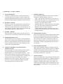
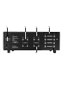
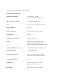
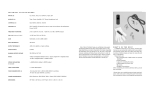
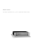
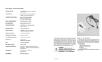
ANTHEM P RE
1L
OPERATI N G M ANU A L
We at Sonic Frontiers hope you will derive many years
of listening pleasure with your new Anthem Pre 1L. This
Operating Manual contains important information regarding the operation and care of the Pre 1L. Be sure to read
this manual carefully and follow these instructions in order
to keep it performing and sounding its best. Please contact Sonic Frontiers if you have any questions, a Customer
Service Representative will be pleased to assist you.
W H AT ’ S I N T H E B O X ?
In addition to the Pre 1L, the Power Supply (their appropriate covers), and the operating manual you are presently
reading (with associated inserts and warranty card), there
are a few more items to take inventory of before steps are
taken to make the Anthem Pre 1L operational.
These items are:
• two matched pairs of 6922 tubes (or equivalent),
totaling 4*
• a glove for handling the tubes
• a detachable AC power cord
• 18 screws
• 1 Philips #1 screwdriver
After completing an inventory of these items, proceed
to the next steps.
*These tubes are carefully measured and matched in
pairs. Take extra care to keep the pairs from being mixed
and mismatched which would degrade performance.
4/21/97 SKU#57388
A
B
D
E
F
C
G
H
I
CONTROL
A
FUNCTIONS
SE LE CTOR S WIT CH
F
This knob is rotated to select a Line Level Input (M overleaf). Note that the Selector Switch is bypassed
when the Tape/EPL(External Processor Loop) mode is
selected by depressing the Tape/EPL-Source button (E).
B
This Light Emitting Diode has three status conditions
identified by different displays. They are:
• DIM - indicates the Power Switch (I) has been initialized and that the Pre 1L is cycling through it’s 45
second turn on sequence. During this turn on
sequence the output will be muted.
• BRIGHT (Normal) - indicates that the Power Switch
(I) is in the ON position (depressed) and that the
Mute Switch (H) is in the out position.
• FLASH (Normal Intensity)- indicates the Pre 1L is
muted; the Mute-Operate button (H) is depressed in
the Mute position.
BALANCE CONTROL
This knob controls the relative balance of the left and
right channels to compensate for any discrepancies
caused by speaker placement, source imbalance, etc.
Full rotation to the left or right of the center detent will
fully attenuate the left or right channels.
C
VOLUME CONT RO L
This knob allows variable control over the Pre 1L output level. Turn it clockwise and the music gets louder!
D
G
HEADPHO NE INPUT JACK
H
M U T E - O P E R ATE BUTT ON
When in the OPERATE position (not depressed), this
button will allow normal operation. When in the MUTE
position (button depressed), the audio signal is prevented from reaching the Main Outputs (K - overleaf).
The LED (F) will flash as a reminder.
TAPE/EPL (E XTE RNAL PROCESSOR L OO P)SOURCE BUTT ON
When this button is in the SOURCE position (button is
not depressed) the signal is routed through the
Selector Switch (A) to the Tape/EPL Output (L - overleaf) connected with a tape deck or external processor such as a surround sound decoder. Listening and
taping is done in this mode. When the button is
depressed the source signal is taken from a tape or
processor source through the Tape/EPL Inputs (N overleaf) bypassing the selector switch.
MON O/S TE RE O BUTTON
When in the ON position (button depressed) the Mono
function is enabled. This function sums all selected
input signals together, and directs them to both channels. As long as the button is depressed a left or a
right mono signal will be sent to both channels of the
preamplifier. All other preamplifier functions will oper ate normally.
The Headphone Jack accepts 1/4” stereo headphone
plugs. Upon insertion of the headphone plug, the main
preamp output is disabled. All other preamp functions
remain operational. Removal of the headphone plug
restores the main output signal.
E
PREAMPLIFIE R LED
I
ON- OFF BUTT ON
When in the ON position (button depressed), all power
supplies within the preamplifier are initiated. A delay of
approximately 45 seconds is required for the power
supplies to stabilize. After the 45 second delay, the
muting relay will engage, and the preamplifier is operational. When in the OFF position (not depressed), the
Pre 1L is OFF.
J
K
L
N
M
CONNECTION
J
FUNCTIONS
D E TACHABLE IEC AC POW ER CORD S OCKE T
Plug the Detachable Power Cord into this socket (see
Figure 4). The Pre 1L is factory set for the correct
operating voltage for the area in which it is sold (see
shipping box for voltage setting). If a different operating voltage is required, please contact an authorized
Sonic Frontiers or Anthem dealer, distributor or the
factory directly.
K
MAIN OUTPUTS O NE AND TWO
These outputs connect to the single-ended inputs of
other units such as power amplifiers or a crossover
unit; connect left channel to left channel and right
channel to right channel. The set of two allows for
easier biamping and greater flexibility when dealing
with components such as electronic crossovers, a
powered subwoofer, etc.
L
TAPE/EPL(EXTE RNAL PROCESSOR L OO P) O UTPUT
This output connects to the single-ended inputs of a
tape deck or external processor; connect left channel
to left channel right channel to right channel. This output always follows the input selection of the Selector
Switch (A).
M LINE LEVEL INPUTS F OR CD, T UN ER
AND AUXILIARY SO URC ES
Line level single-ended source connection may be
made to these 4 sets of RCA connectors; connect left
channel to left channel right channel to right channel.
N
TAPE/EPL INPUT
This input accepts a single-ended RCA input connection from a tape deck or external processor;connect
left channel to left channel right channel to right channel. These inputs are activated when the Tape/EPLSource button (E) is depressed.
WARNING- DISCONNECT THE AC
DETACHABLE POWER CORD FROM THE
Pre 1L AND WAIT 5 MINUTES BEFORE
REMOVING COVER, TUBES OR FUSE.
SETTING
UP
The Pre 1L comes with four tubes, as follows:
6922 (LV1 & V1, LV2 & V2)
The 6922 tubes may be replaced with a matched set of
ECC88/6DJ8s or E188CC/7308s with no circuit modification. These tubes were chosen for their reliability and
extremely low noise. The amplifier topology used in the
Pre 1L delivers exceptional performance using the 6922
tube. The tubes’ low noise heightens dynamics and provides a natural tonal balance.
INSE RT ION O F THE TUBES
1. Using the screwdriver supplied, remove the cover of
the Pre 1L. For your convenience, only four of the screws
are installed at the factory.
2. When handling the tubes, it is recommended that the
cotton gloves provided be worn to prevent skin oils from
depositing on the glass surface.
3. Noting the location of the tube sockets in the top view
photo (Figure 2) or directly on the PC Board, inspect the
tubes for corresponding labels and markings. Once locations are mapped, take a tube and inspect the pins, noting the larger space between two of the pins (see Figure
1). This space will match with the socket. Insert each
tube into the appropriate tube socket, making sure all
pins and pin holes are aligned. Do not force the tubes
into the sockets. “Rock” the tubes gently while pushing
slowly until each tube is firmly seated.
Note the larger space
between two of the pins and
holes for proper alignment
of tube and socket.
Figure 1
LV2
V2
LV1
V1
FUSE
LOCATION
Figure 2 - Tube and Fuse Location
8dB
16dB
24dB
SW101
Figure 3 - Gain Switches (Viewed from front panel.)
Gain Switches shown in 8dB position.
SW102
After the insertion of the tubes, replace the cover and fasten it with the screws provided. The Pre 1L is now ready
for operation. For further information on tube replacement,
NOS (New Old Stock) tubes, contact your dealer, a Sonic
Frontiers Customer Service Representative or The Parts
Connection, a division of Sonic Frontiers.
OPERATION
Before plugging in the Pre 1L, check to see that the unit is
configured for the correct AC line voltage for country of
use. The operating AC line voltage is indicated on the side
of the shipping box. If the Pre 1L is set incorrectly for the
country in which it is to be operated, contact the dealer or
distributor in your area. If the unit is configured properly,
continue with operation.
Connect the Detachable Power Cord to the Pre 1L chassis
rear (see Figure 4). Plug your Pre 1L into the AC power
source.
Note: Never unplug your Pre 1L during operation.
First shut off your Power Amplifier, mute the Pre 1L
by depressing the Mute/Operate button (H), and
remove AC power by pressing and releasing
Power Switch (I).
All remaining connections to external equipment are made
with single-ended (unbalanced) type audio interconnect.
Connect source units to the Inputs of the Pre 1L (M) or
Tape Input (N); left channel to left channel and right channel
to right channel.
If a tape or other line level recording or processing device
is being implemented, connect the left and right audio output of the unit to the corresponding left and right Tape/
EPL Input (O) of the Pre 1L. Also connect the left and right
Tape/EPL Outputs (M) on the Pre 1L to the corresponding
left and right audio inputs of the external device.
Connect Set 1 of the Main Outputs (L) on the Pre 1L to a
stereo amplifier or two mono amplifiers; left channel to left
channel and right channel to right channel. Set 2 of the
Main Outputs (L) may be used under different situations
and in combination with Set 1. These situations include
biamping, the use of active crossovers, powered subwoofers and other equipment; all situations being unique
and system dependent. Refer to the instruction manuals
provided with the other equipment before using the second set of Outputs.
The Pre 1L is now ready for operation. Power the Pre 1L by
placing the On-Off button (I) in the ON position. The Power
Indicator LED (F) will stay DIM for approximately 45 seconds. During this time, the Main Outputs are muted while
the tubes are warming up and stabilizing. As soon as the
Power Indicator LED is at steady, normal intensity, the Pre
1L is ready for operation.
Select a ready signal source with the Selector Switch (A).
Balance is adjusted through use of the Balance Control (B);
turning it left and right will adjust the left and right levels
respectively. The center detent is an indicator for equal, or
balanced, left and right levels.
Volume is adjusted through use of the Volume Control (C).
Turning this control clockwise increases the volume level
of both channels. Be sure the level is sufficiently low when
turning the unit ON or returning to the OPERATE mode
after MUTING, to prevent damage to speakers, amplifiers
or the Pre 1L itself.
To record from a source, place the Tape/EPL-Source button (E) in the SOURCE position, select the source material
you wish to record via the Selector Switch (A), and commence recording. To play back a tape recording, place the
Tape EPL/ Source button in the TAPE position.
Muting the Pre 1L is achieved by placing the Mute/Operate
button (H) in the MUTE position (button depressed); the
output signal is then cut off. To resume listening, place the
button in the OPERATE position (not depressed).
NOTE: Under no circumstances should you replace the AC
power fuse with one of a higher current rating! Doing so may
cause further damage to the Pre 1L and will also void the
warranty. In addition, your continued protection from risk of
fire or shock would be seriously compromised.
• Ensure the tubes are plugged firmly into their sockets as
described in “INSERTION OF THE TUBES”.
4. Be sure the rest of the system is functioning properly (i.e.
source unit, power amplifiers, cables and connections, etc.).
5. With tubes, fuses, covers and power cords in place, check
that the LED (F) is lit. If all of the above troubleshooting steps
have been followed and the LED is not lit, contact your dealer
or distributor for assistance.
Figure 4 - Alignment of the AC power connector and detachable cord.
TROUBLESHOOTING
If at any time the Pre 1L fails to work properly, consult this
checklist:
1. Check that the AC Detachable Power Cord is plugged into
the Pre 1L Detachable Power Cord Socket (I) and is connected to a live source of AC power. For instance, if using a
power bar, check that the bar is turned on.
2. Ensure that all Input and Output connections are secure for
a proper electrical contact.
3. DISCONNECT THE AC POWER CORD, wait 5 minutes,
remove the chassis covers from the Pre 1L and check that:
• A “slow-blo” fuse, with a rating of 0.5 Amp/250 V (0.25
Amp/250 V for European and Asian versions), is installed on
the circuit board under the soft plastic cover (see figure 5).
• The AC power fuse is intact and has not blown. If the fuse
has blown, the thin metal conductor will have melted and the
glass may appear “smoked”. If the fuse has blown, replace
with a fuse of the same rating (0.5 Amp/250V fast-blo for 100
to 120 volt countries and .25 Amp/250V fast-blo for 220 to
240 volt countries). (See Figure 5.)
Figure 5 - Fuse location.
WARNING-DISCONNECT THE AC
DETACHABLE POWER CORD FROM THE
Pre 1L AND WAIT 5 MINUTES BEFORE
REMOVING COVER, TUBES OR FUSE.
BR EAK- IN TI ME
PACKI NG MAT E R I A L S
As with all audio electronic products, the ultimate sonic
character of the Pre 1L will not be realized until and unless
the unit receives a minimum of approximately 70 hours
of signal break-in time (i.e. the Pre 1L is on and producing
an output signal).
Please retain all of the packing material and shipping boxes
for your Pre 1L. They are custom designed to prevent shipping damage from occurring. Sonic Frontiers, Inc. will
accept no responsibility for any damage occurring to a Pre
1L that is shipped in packing material other than the original
Sonic Frontiers packing material.
P LACE MENT FOR PR OPER VENTILAT I O N
DISCLAIMER OF LIABILITY
Allow at least 4” (15 cm) of clear space above the Pre 1L
chassis for proper ventilation, making sure the air vent slots
in the chassis cover remain unobstructed. Also, be sure
that the Pre 1L is placed on a secure, hard and level surface (not on carpet).
Under no circumstances does Sonic Frontiers, Inc.
assume liability or responsibility for injury or damages sustained in the use or operation of this equipment or for
damages to any other equipment connected to it.
Sonic Frontiers, Inc. reserves the right to make design
changes or improvements without the obligation to revise
prior versions. All specifications are subject to change
without notice.
S AFETY INSTRU CTI ONS
1. Ventilation - Although your Pre 1L generates only nominal
heat in use, be sure that the ventilation slots in the top cover
have at least 4” of unobstructed air space above them.
2. Water and Moisture - This product should not be used
near water. To prevent fire or shock hazard, do not expose
this product to rain or moisture.
3. Heat - This product should be situated away from heat
sources such as radiators, heat registers, stoves, or other
appliances which produce heat.
4. Power Sources - This product should be connected to an
AC power source of the proper rated voltage. The original
shipping container will stipulate the AC voltage this unit can
operate with correctly.
5. Cleaning - A regular dusting with a soft, non-abrasive
cloth will generally keep the finish of the faceplate and chassis looking like new. At no time should you allow any liquid to
come in contact with the Pre 1L; it may run into the electronic circuitry and cause damage which will not be covered
under your warranty.
6. Servicing - Do not open this product. No user serviceable
parts inside. Refer servicing to an authorized service technician.
7. Non-Use Periods - The power cord of this product should
be unplugged from the outlet when left unused for an
extended period of time.
8. Do not remove the Pre 1L covers while the unit is “on”, or
connected to an AC power source. Cover screws could fall
through the ventilation slots and cause electrical damage to
the Pre 1L.
LIMITED F IVE YEAR WA R R A N T Y
Sonic Frontiers, Inc. warrants to the purchaser that each
Pre 1L is free of manufacturing defects for a period of five
(5) years from the date of purchase. This five (5) year
limited non-transferable warranty excludes all vacuum
tubes, which we warrant for a period of twelve (12)
months. To receive this warranty, the original purchaser
must complete and mail to Sonic Frontiers, within thirty
(30) days from the date of purchase, the enclosed
Warranty Registration Card. Sonic Frontiers, Inc. will then
validate the warranty to the original purchaser. This warranty is subject to the following conditions and limitations:
Units to be repaired by Sonic Frontiers, Inc. must be sent
shipping and insurance prepaid by the original purchaser
in the original packing material. A returned product should
be accompanied by a written description of the defect.
Repaired units will be returned by Sonic Frontiers, Inc.
shipping and insurance prepaid.
All other warranties or conditions either written or implied
are void.
Note: In foreign markets (anywhere outside of Canada and the
USA), the warranty is supplied by the authorized International
Distributor. Exact terms and conditions may vary.
1. Warranty applies only to the original purchaser.
2. This warranty is void and inapplicable if the product
has been handled other than in accordance with the
instructions in this Owner’s Manual, abused or misused,
damaged by accident or neglect or in being transported,
or the defect is due to the product being tampered with,
modified or repaired by anyone other than Sonic Frontiers,
Inc. or an authorized Sonic Frontiers repair depot.
3. Warranty does not cover normal maintenance.
4. Sonic Frontiers, Inc. shall not be responsible in any way
for consequential or indirect damages or liabilities resulting
from the use and operation of the product covered herein
or resulting from any breach of this warranty or any
implied warranty relating to said product.
During this period, Sonic Frontiers, Inc. will repair or
replace any defective components free of charge. A
Return Authorization Number (RA Number) is required
before any product is returned to our factory for any reason. This number must be visible on the exterior of the
shipping container(s) for Sonic Frontiers to accept the
return.
Units shipped to us without a Return Authorization Number
or without a visible RA Number on the exterior of the shipping container(s) will be returned to the sender, freight
collect.
This symbol is intended to alert the user to the
presence of uninsulated “dangerous voltage”
within the product’s enclosure that may be of
sufficient magnitude to constitute a risk of electric shock to persons.
This symbol is intended to alert the user to
the presence of important operating and
maintenance (servicing) instructions in the
literature accompanying the appliance.
TECHNICAL
SPECIFICATIONS
(AC line set at 117V 60Hz)
FREQUENCY RESPONSE :
2 Hz to 130 kHz -0.5 dB;
> 250 kHz -3.0 dB at 1VRMS output
THD & N (Output at 1V RMS) :
< 0.1% from 20 Hz to 20 kHz
GAIN:
Selectable, 24, 16 & 8dB settings @ 1kHz
INPUT IMPEDANCE:
40k ohms
OUTPUT IMPEDANCE:
<135 ohms @ 1kHz, all gain settings.
RATED OUTPUT:
1 VRMS
MAXIMUM OUTPUT VOLTAGE:
30 VRMS at 1% THD
NOISE:
< 115µV unweighted wideband noise
Approx. 60µV IHF A-weighted noise
-90 dB A-weighted below a 1 VRMS output
STEREO SEPARATION (Crosstalk):
> -60dB @ 1kHz relative to 1 VRMS output
TUBE COMPLEMENT:
4 - 6922 (6DJ8 types)
FUSE REQUIREMENTS (1):
.5 A slow-blo (100-120VAC countries),
.25A slow-blo (220-240VAC countries)
POWER REQUIREMENTS:
40VA
DIMENSIONS:
19” Wide x 11” Deep x 5.25” High
(48 cm x 28 cm x 13.4 cm)
NET WEIGHT:
Approx. 20 lbs (9 kg) - unpacked
279 0 BR I GHTO N R OAD, O AKVIL LE , ONTA RIO , CA NA DA
So n i c
F r o n t ie r s
E - m a i l
c a n
b e
r e a c h e d
9 : 00
S F I @ s o n i c f r o n t i e r s . c o m
D E S I G N E D
A N D
a m
W o r l d
M A N U F A C T U R E D
t o
L6H 5T4
6 : 0 0
W i d e
B Y
p m
W e b
T EL: (90 5) 82 9 -383 8
( E .S . T. )
S i t e
S O N I C
or
2 4
h o u r s
FA X: ( 90 5) 829 -3 03 3
a
d a y
b y
f a c s i m i l e
h t t p : / / w w w . s o n i c f r o n t i e r s . c o m
F R O N T I E R S
I N C O R P O R A T E D