1
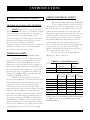
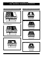
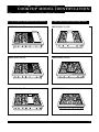
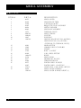
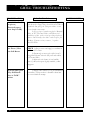
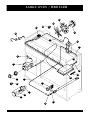
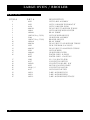
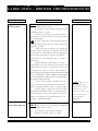
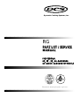
Dynamic Cooking Systems, Inc.
RG
PART LIST / SERVICE
MANUAL
PROFESSIONAL
48”, 36” , 30” ALL-GAS RANGE,
48” AND 36” GAS COOKTOP MODELS
CANADIAN GAS ASSOCIATION
R
APPROVED
Retain this manual for future reference.
As product improvement is an ongoing
process at DCS, we reserve the right to
change specifications or design without
notice.
Litho in USA
P/N 10582 REV 2 6/98
5800 Skylab Road Huntington Beach, CA 92647
(714) 372-7000
Fax (714) 372-7001
Direct Parts/Customer Service (888) 281-5698
Dynamic Cooking Systems Inc.
I N T RO D U C T I O N
D C S S E R V I C E M A N UA L
Thisservice manual covers Models DCS-(RG)
(C) - (30) (36) (48) - (4) (6)-(GD) (GL) (GG)
The DCS Professional Series of Gas Ranges
was designed to provide features tailored to a customer with high expectations. This Service Guide was
created with the goal of minimizing customer inconvenience and having anynecessaryrepairs done
quickly and correctly. If, in the course of using this
manual, you should haveany difficulty, or you feel
that some important item has been omitted, please let
us know with a phone call or Fax.
Thismanualwascreated for use by a qualified
technician, authorized by the DCS Service
Department.
To identify the Model and Serial #, locate and
read the appliance rating plate. Therating plate is
located on the rear left side of the interior top burner
box(remove the top burner grates and bowls), or on
the right side of the burner box on some six burner
models. In general, our Model numbering logic is as
follows;
1 2 3 4
ie. DCS-RG-484GG
1)(RG) denotes a Range with gasovens and
an integralgas cooktop, (C) denotes a gas cooktop.
2) (48)[47 7/8], (36)[35 7/8], or (30)indicates
unit nominal Width (in inches)
3)(4),or(6)indicates # of open top burners
4)(GG)indicates a GriddleandChar-Rock
Grill, (GD)indicatesathermostatically controlled
Griddle section, or (GL)indicatesaChar-Rock Grill
section
Beforeservicing the range, it is firstimportant
toaccurately define the exact details of the complaint
and then assess the cause of the defect. Complete
Installation Instructionsare includedwitheachappli-
ance and should be consulted to checkforproperinstala
l tionpractices.Chargesrelated to Installationare not
coveredunderwarranty. Common foraproduct this
largeandheavyisdamage due to reckless handling by
truckingfirms, or Installation personnel moving the
product into position.
What followsisanoverview of DCS warranty
provision. Reviewthewarranty policy to determine
what is covered under the warrantyrepairprovisions
andwhat will not be covered. Before beginningany
work, the proposedservice should either be authorized
by DCS, or, in the event the work is not coveredunder
warranty, the customer be informed of their responsibility fortherepaircharges.
TABLE
OF
CONTENTS:
Introduction / Warranty Introduction ...................1
Warranty Information..................................................2
Troubleshooting-General ...........................................3
Orifice Hood / Pin Size Chart- L.P / Nat. Gas..3
Model Identification ................................................4-5
Outer Body Parts.......................................................6-7
Backguards .................................................................8-9
Open Top Burners Partlist.................................10-11
Troubleshooting - Leaks ..........................................12
Troubleshooting - Open Top Burners ................12
Griddle Partlist ......................................................13-14
Troubleshooting - Griddle .................................15-16
Grill Partlist ............................................................17-18
Troubleshooting - Grill .......................................19-20
Large Oven / Broiler Partlist ............................21-22
Troubleshooting - Oven / Broiler....................23-25
Small Oven Partlist...............................................26-27
Troubleshooting - Small Oven..........................28-29
1
WA R R A N T Y
Thiswarranty covers the following cooktops and ranges. DCS RG 484 GG, DCS RG 486 GL, DCS RG 486
GD, DCS RG 364 GD, DCS RG 366, DCS RG 364 GL, DCS RG 304, DCS C 486 GL, DCS C 486 GD, DCS
C 484 GG, DCS C 364 GD, DCS C 366, DCS C 364 GL.
L E N G T H O F WA R R A N T Y
One (1) Year Full - Covers the entire product
Five (5) Years Limited - Surface burners, Griddle burners, Grill burner, Oven burner
Ten (10) Years Limited - Porcelain oven, Porcelain inner door panels
DCS W I L L PAY F O R ::
All repair labor and replacement parts, for parts found to be
defective, within the warranty period due to materials or workmanship. Service must be provided by Authorized Factory Agent
during normal working hours.
DCS W I L L N OT PAY F O R ::
Installation or start-up
Normal adjustment to burners, gas regulators, etc.
Cleaning of igniters and/or general maintenance
Shipping damage
Service by an unauthorized agency. Damage or repairs due to
service by an unauthorized agency or the use of unauthorized
parts.
Overtime, weekends, holiday labor rates
Discoloration of the griddle plate
Improper installation, such as: no regulator, improper hookup, etc.
Chipping of porcelain enamel grates
Service visits to:
- Teach you how to use the appliance.
- Correct the installation. (You are responsible for providing electrical wiring, gas installation and other connecting facilities.)
- Reset circuit breakers or replace home fuses.
- Damage caused from accident, abuse, alteration, misuse,
incorrect installation or installation not in accordance with
local codes.
- Repairs due to other than normal household use.
- Units installed in non-residential applications such as:
day care centers, bed and breakfast centers, churches,
nursing homes, restaurants, hotels, schools, etc.
This warranty applies to appliances used in residential applications;
it does not cover their use in commercial situations.This warranty
is for products purchased and retained in the 50 states of the
U.S.A., the District of Columbia and Canada. This warranty
applies even if you should move during the warranty period.
Should the appliance be sold by the original purchaser during the
warranty period, the new owner continues to be protected until
the expiration date of the original purchaser's warranty period.
This warranty gives you specific legal rights. You may also have
other rights which vary from state to state.
H OW TO O B TA I N S E RV I C E
Forwarrantyservice,contactyourlocalDCSauthorizedserviceagency.Providehimwiththe Model #, Serial #, gas
type and date of installation, and a brief description of the problem. If youneedassistanceinlocatingtheauthorizedserviceagencyinyourarea,contactyourlocaldealer.HewillhavealistingofauthorizedDCSserviceagentsinyourarea. We
wantyoutoremainasatisfiedcustomer.Ifaproblemdoescomeupthatcannotberesolvedtoyoursatisfaction,pleaseletus
know. Write: Dynamic Cooking Systems Inc., Customer Service Department, 5800 Skylab Road,
Huntington Beach CA 92647. Or call (714) 372-7000 or fax us at(714) 372-7001.
2
I N T RO D U C T I O N
G E N E R A L I N S T RU C T I O N S :
STEP ONE: ISOLATING THE PRO B L E M
N OTE: Before addressing any specific
problem the unit may have, it is advisable to help
isolate the nature of the problem byrunning a
general check of the 1) Gas Supply and 2)
Electrical Supply. The following procedure will
narrow the possibilities and help direct you to
the source of the problem. A detailed
Troubleshooting section with specific symptoms
and likely corrective courses of action follows
each sub-assembly Partlist section.
CHECK GAS SUPPLY
First, check to see if the gas has been turnedon.
Next, gain access to the regulator byremoving the grates over the cooktop burners on the far
left hand side of the cooktop. Beneath the grates,
towards the rear of the burner box, the regulator is
located between the manifold and rear incoming gas
line. Check the top of the regulator to see that it is set
up for the type of gas supplied to the unit. Thecap
on top of the regulator indicates whether the unit is
set up for NATURAL or L.P. gas.
When the gassupply is on, check the gas
pressure with a manometer. The front main open top
burner orifice is the most convenient place to check
gaspressure. To access the main burner orifice,
remove the four(4)screwsthat hold the burner
hangerdown and A) move aside the burner assembly
or B) disconnect the igniter wires and remove the
entire burner / hangerassembly. Hook up a flexible
line to the main burner orifice, turn that burner on...
the pressure should read 5.0" W.C. for Natural Gas,
and 10.0" W.C. for L.P. Gas. Turn on other burners
andcheck for an excessivedrop in pressure. A large
drop in pressure indicates a gassupplyproblem related to installation, not covered byservice warranty.
CHECK ELECTRICAL SUPPLY
First, check to see if the electricity has been turnedon.
Next, checkpower to the cord in the back of
the rangeandat the wallreceptacle. If power is OK
there, the nextarea to check will be at the service disconnect located behind the valve panel. The Valve
Panel can be removed byremoving the five(5)screws
that hold it in place. Two(2)screwsare locatedat
each end of the panel, while one (1) screw(painted
Red) behind a Burner Control knob must also be
removed before the valve panel can be removed.
Once the ValvePanel has been removed, unplug and
check forpower to the female side of the plug.
Between 110 & 120 volts should be present, if not,
there is a problem with the cord.
Check forpowerat the Terminal Blocks,
(Black= Live, White = Neutral)
ORIFICE or PIN SIZE References:
Gas Type
IncomingPressure
Pressure Regulator
to Regulator
Supplies
NATURAL 7.0" to 9.0" W.C.
5.0" W.C.
L.P.
11" to 14.0" W.C.
10.0" W.C.
Orifice Size
Nat. (DMS)
51
Center Simmer
78
Grill
48
Griddle
48
Infra Red Broiler
47
Small Oven
48
Large Oven
38
Size
Open Top
Pin Size Orifice
LP (DMS) LP (DMS)
57
50
87
80
55
55
55
55
55
55
55
55
52
52
*NOTE: Ensure the Air Shutter is installed whenconverting
an I/R Broiler to L.P,. See Gas Hookup Section, Range
Installation Manual.
3
RG M O D E L I D E N T I F I C AT I O N
48" GAS RANGE MODEL IDENTIFICATION:
36" GAS RANGE MODEL IDENTIFICATION:
MODEL DCS-RG-484 GG
MODEL DCS-RG-364 GD
MODEL DCS-RG-364 GL
MODEL DCS-RG-486 GL
MODEL DCS-RG-366
MODEL DCS-RG-486 GD
MODEL DCS-RG-304
4
COOKTO P M O D E L I D E N T I F I C AT I O N
48" GAS COOKTOP MODEL IDENTIFICATION:
36" GAS COOKTOP MODEL IDENTIFICATION:
MODEL DCS-C-484 GG
MODEL DCS-C-364 GD
MODEL DCS-C-486 GL
MODEL DCS-C-364 GL
MODEL DCS-C-486 GD
MODEL DCS-C-366
5
B O DY PA RT S A S S E M B LY
33
1
2
25
32
4
29
23
25
22
28
3
19
18
27
8
17
24
20
6
21
16
5
7
15
10
14
9
13
30
26
31
12
11
582fig02.eps
27” Oven Door Assembly
90184-02
12” Oven Door Assembly
90184-01
RG 304 Oven Door Assembly 90184-03
6
B O DY PA RT S A S S E M B LY
PA RT S L I S T:
ITEM #
1
2
3
4
5
6
7
8
9
10
11
11A
12
13
14
15
16
17
18
19
20
21
22
22A
23
24
25
26
27
28
29
30
31
PART #
DESCRIPTION
90104-01
90104-02
90104-03
90100-PA
90100-01
90100-02-PA
90102-PA
90102-01-PA
90102-02-PA
90099-PA
90101-PA
90101-01-PA
90101-02-PA
90103-PA
90103-01-PA
90347
90347-01
90103-02-PA
90090-01
90217-01
90114-01
90090-02
90217-02
90114-02
18052-02
90164
90219
90228
150034-3
90186-PC
90200-PC
150034-1
15097
14131
90106
90094-02
90184-02(27”), 90184-01(12”)
90184-03
17001
17001-03
90187-02
90187-03
18164
90112
90187-01
90107
90097
90113
90111-PC
15001-34
15001-09
90068-01-L/H, 90068-02-R/H
90212-36" , 90234-30"
90202-02-L/H, 90202-01-R/H
90213-36" , 90208-30"
30313-3
150034-2
90054-01 (R), 90054-02 (L)
90053-02 (R), 90053-01 (L)
90259-01(R), 90259-02(L)
90196-01-PC
90196-02-PC
90273-PC
90055-01(R), 90055-02(L)
90050-01(L), 90050-02(R)
90163
19003-1(BAKE), 19003-3(BROIL)
19044-01(BAKE), 19044-02(BROIL)
19003-02
RG 48 LANDING LEDGE
RG 36 LANDING LEDGE
RG 304 LANDING LEDGE
RG 484GG VALVE PANEL
RG 486GD VALVE PANEL
RG 486GL VALVE PANEL
RG 366 VALVE PANEL
RG 364GD VALVE PANEL
RG 364GL VALVE PANEL
RG 304 VALVE PANEL
C 484GG VALVE PANEL
C 486GD VALVE PANEL
C 486GL VALVE PANEL
C 364GL VALVE PANEL
C 364GD VALVE PANEL
RGA 304 (SS) VALVE PANEL
RGA 304 (WHITE) VALVE PANEL
C 366 VALVE PANEL
RG 48 RIGHT BODY PANEL
RG 36 RIGHT BODY PANEL
RG 304 RIGHT BODY PANEL
RG 48 LEFT BODY PANEL
RG 36 LEFT BODY PANEL
RG 304 LEFT BODY PANEL
LEVELING LEG
RG 48 KICK PANEL ASSEMBLY
RG 36 KICK PANEL ASSEMBLY
RG 304 KICK PANEL ASSEMBLY
HINGE RECEPTACLE
27" DOOR INSIDE LINER (RG 48/36)
(RG 304) DOOR INSIDE LINER
27" OVEN DOOR HINGE (RG 48/36)
(RG 304) OVEN DOOR HINGE
WINDOW PACK
27" OVEN OUTSIDE DOOR PANEL (RG 48/36)
(RG 304) OVEN OUTSIDE DOOR PANEL
OVEN DOOR ASSEMBLY
RG 304 DOOR ASSEMBLY
DCS LOGO -SM. (COOKTOPS)
DCS LOGO -LG. (RANGES)
27" OVEN DOOR HANDLE (RG 48/36)
(RG 304) OVEN DOOR HANDLE
DOOR HANDLE ENDCAP
12" DOOR OUTSIDE PANEL
12" DOOR HANDLE
27" DOOR INSULATION RETAINER (RG 48/36)
(RG 304) DOOR INSULATION RETAINER
12" DOOR INSULATION RETAINER
12" DOOR INSIDE PANEL
BOLT - DOOR HANDLE
SCREW - DOOR TOP
DRIP PAN - 48"
DRIP PAN
DRIP PAN HANDLE - 48"
DRIP PAN HANDLE
DRIP PAN LINER (UNDER GRILL / GRIDDLE ONLY)
12" OVEN DOOR HINGE
COOKTOP 48 SIDE TRIM
COOKTOP 36 SIDE TRIM
RG 366 FRONT PANEL
27” OVEN BOTTOM
12” OVEN BOTTOM
RG 304 OVEN BOTTOM
C 48”, 366 only SIDE INSULATION RETAINER
C 364 SIDE INSULATION RETAINER
RG / RGA CENTER SPACER- GRATE
27” OVEN RACK
RG / RGA 304 OVEN RACK
12” OVEN RACK
7
BACK GUARDS ASSEMBLY
RANGE HIGH SHELF BACKGUARD
COOKTOP HIGH SHELF BACKGUARD
1
14
2
3
15
17
4
* [InsulationPart # 140092
All Models]
13
* Insulation
6
5
16
RANGE LOW BACK BACKGUARD
COOKTOP LOW BACK BACKGUARD
7
187
9
3
8
19
* Insulation
* Insulation
RANGE ISLAND TRIM BACKGUARD
20
10
COOKTOP ISLAND TRIM BACKGUARD
11
12
21
* Insulation
8
BACK GUARDS ASSEMBLY
PA RT S L I S T:
ITEM #
1
2
3
4
5
6
7
8
9
10
11
12
13
14
15
16
17
18
19
20
21
PART #
DESCRIPTION
90089
90089-01
90089-02
90088
90088-01
90088-02
90041
90041-01
51147
90240-01
90240-02
90240-03
90087
90087-01
90087-02
90236
90236-01
90236-02
90040
90040-01
90040-02
90039
90039-01
90039-02
90038
90038-01
90038-02
90245-01
90245-02
90245-03
90248-01
90248-02
90248-03
90249-01
90249-02
90249-03
90236
90236-01
90240-01
90240-02
90371-01
90371-02
90369-01
90369-02
90370-01
90370-02
30130-48(48"), 30130-36(36")
30118-03(48"), 30118-02(36")
30128-03(48"), 30128-02(36")
90058
90052
RG 48 HIGH SHELF BACK SHEET
RG 36 HIGH SHELF BACK SHEET
RG 304 HIGH SHELF BACK SHEET
RG 48 HIGH SHELF INSULATION RETAINER
RG 36 HIGH SHELF INSULATION RETAINER
RG 304 HIGH SHELF INSULATION RETAINER
RG 48 HIGH SHELF / LOW BACK TOP
RG 36 HIGH SHELF / LOW BACK TOP
RG 304 HIGH SHELF / LOW BACK TOP-GCRG 304
RG 48 HIGH SHELF WELD ASSY.
RG 36 HIGH SHELF WELD ASSY.
RG 304 HIGH SHELF WELD ASSY.
RG48 HIGH SHELF FRONT SHEET
RG36 HIGH SHELF FRONT SHEET
RG304 HIGH SHELF FRONT SHEET
RG48 HIGH SHELF BOTTOM ENCLOSURE
RG36 HIGH SHELF BOTTOM ENCLOSURE
RG304 HIGH SHELF BOTTOM ENCLOSURE
RG 48 LOW BACK BACK SHEET
RG 36 LOW BACK BACK SHEET
RG 304 LOW BACK BACK SHEET
RG 48 LOW BACK INSULATION RETAINER
RG 36 LOW BACK INSULATION RETAINER
RG 304 LOW BACK INSULATION RETAINER
RG 48 LOW BACK FRONT SHEET
RG 36 LOW BACK FRONT SHEET
RG304 LOW BACK FRONT SHEET
RG48 TOP ASSEMBLY
RG36 TOP ASSEMBLY
RG304 TOP ASSEMBLY
RG 48 BACK SHEET
RG 36 BACK SHEET
RG 304 BACK SHEET
RG 48 INSULATION RETAINER
RG 36 INSULATION RETAINER
RG 304 INSULATION RETAINER
COOKTOP 48 HIGH SHELF BOTTOM ENCLOSURE
COOKTOP 36 HIGH SHELF BOTTOM ENCLOSURE
COOKTOP 48 HIGH SHELF WELD ASSY.
COOKTOP 36 HIGH SHELF WELD ASSY.
COOKTOP 48 TOP CAP
COOKTOP 36 TOP CAP
COOKTOP 48 HIGH SHELF FRONT SHEET
COOKTOP 36 HIGH SHELF FRONT SHEET
COOKTOP 48 HIGH SHELF BACK SHEET
COOKTOP 36 HIGH SHELF BACK SHEET
LOW BACK TOP CAP
LOW BACK BACK SHEET
LOW BACK FRONT SHEET
ISLAND TRIM - 48"
ISLAND TRIM - 36"
9
O P E N TOP BU R N E R A S S E M B LY
ELECTRICAL SCHEMATIC:
1
3PC BURNER
2PC BURNER
4A
2
4B
3
*IT IS CRITICAL FOR PROPER PERFORMANCE THAT THE SWITCHES
SUPPLYING POWER TO THE SPARK MODULE ARE PLUGGED INTO
THE SAME NUMBER TERMINAL AS THE ELECTRODE SERVING THE
BURNER IS PLUGGED INTO (e.g.- OPEN TOP SPARK IGNITER OUTPUT
#1 MUST BE ON THE SAME BURNER SERVED BY THE OPEN TOP
SWITCH PLUGGED INTO POWER INPUT # 1
4C
5
6
9
8
33
28
33
7
19
33
18
17
16
15
10
27
11
12
33
13
26
20
25
21
23
24
29
14
22
582FIGOI.eps
10
O P E N TOP BU R N E R A S S E M B LY
PA RT S L I S T:
ITEM #
1
1A
2
3
4A
4B
4C
5
6
7
8
9
10
11
12
13
14
15
16
17
18
19
20
21
22
23
24
25
26
27
28
29
30
31
32
33
PART #
12112
15002-32
12131
12130PC
12104
12102
12101
12105
12093
12094
15001-09
15020-29
14000
12113
12115
15004-04
13236
12116
12114
16006
15109
16075
16005
13071
14006-PL
14125
14124
13070
13005-80
13005-80
13005-50
13005-50
13069
12100
18170
15002-02
90129
90085
90084
16131-01
DESCRIPTION
TOP HALF GRATE
GRATE LEVELING SCREW
SIMMER CAP
BURNER PORT RING
SIMMER TUBE CAP
SIMMER BURNER CAP
SIMMER BURNER RING
SIMMER BURNER BOWL
ELECTRODE
ELECTRODE SPRING CLIP
BURNER BASE SCREWS
VENTURI BOLT
VENTURI GASKET
MAIN VENTURI, REAR
SIMMER VENTURI, REAR
VENTURI NUT
SPARK MODULE
SIMMER VENTURI, FRONT
MAIN VENTURI, FRONT
TERMINAL BLOCK
VALVE SCREW / PLUG / WASHER
POWER CORD - RANGES
POWER CORD - COOKTOPS
SPARK SWITCH / SIMMER, STD. BURNER
BEZEL
SIMMER BURNER KNOB
SIMMER BLOCK O-RING
SIMMER BLOCK
SIMMER ORIFICE HOOD, LP GAS
SIMMER ORIFICE HOOD, NATURAL GAS
ORIFICE HOOD, LP GAS
ORIFICE HOOD, NATURAL GAS
SIMMER VALVE
SIMMER BURNER BASE
OVEN FEED ADAPTER
SCREW
BURNER HANGER
GRATE SUPPORT (L)
GRATE SUPPORT (R)
ELECTRODE WIRE
11
L E A K / O P E N TO P T RO U B L E S H O OT I N G
PROBLEM A R E A :
WHAT TO DO:
Customer smells gas
at all times
CHECK for LEAKS at:
A) The two brass elbows coming from the
1/2"NPT pipe between the regulator and manifold
B) Along the manifoldat every nut/washer
point and plug
C) At all connection points between tubing
andthermal valvesat grill, griddle, and Small Oven(behind the front Kick Panel) locations.
D) At the Dual Thermal Valve located in the
back of the range behind the Griddle or Grill assembly.- To access the Dual T-Valve, the Griddle or Grill
assembly must be removed along with the rear
service cover.
Customer smells gas
only when Open Top
Burners, Large Oven,
or Grill are in operation
CHECK for LEAKS at:
A) The Thermal Valve and connections
supplying the Large Ovenat the front of the unit,
behind the KickPanel, with oven on.
B) The Thermal Valve and connections
supplying the Grill, with Grill turned on.
C) O-Ring between the Simmer Blockand
Simmer Valve for all Open Top Burners, with
burners on
Open Top Burner
Doesn't Light
Is the igniter sparking? Thespark should be
jumping to the brassburner ring.
A) Make surethat the lead to the electrode is
secure, as well as the lead to the Spark Module and
that there is poweralso.
B)Spark Switchesat control knobs should be
checked forpower to and coming out from (with
knob in "lite" position. If there is powergoing to, yet
not coming out the other side, replacesparkswitch.
C) See Open Top Burner Lighting and
"Adjustable Low Setting" sections in the Installation
Manual.
12
?
U S E F U L N OT E S :
N OTE: If using a
soap and water solution when checking
for leaks, be careful
not to get any water
on Spark Switches, as
doing so will cause a
short in the switch.
N OTE: It is
important that the
correct # wire be
traced from the Spark
Switch, to the Spark
Module, to the
Burner Electrode.
G R I D D L E A S S E M B LY
ELECTRICAL SCHEMATIC:
1
25
L
N
2
3
4
22
21
5
6
20
7
16
26
17
15
23
8
18
19
14
13
9
24
12
10
11
13
G R I D D L E A S S E M B LY
PA RT S L I S T:
ITEM #
1
2
3
4
5
6
7
8
9
10
11
12
13
14
15
16
17
18
19
20
21
22
23
24
25
26
14
PART #
90254
90140
90192-01
90192-02
90133
12005-1
16009-1
90141
30313-3
90045-01
13073
18017
18166
18165
15109
16046-1
13010-3
14006-PL
14129
16077
16006
16075
16005
16077
13005-48
14026
15001-09
16046-2
DESCRIPTION
GRIDDLE COVER
GRIDDLE FLUE COVER
GRIDDLE / GRILL FRONT TRIM
GRIDDLE FRONT TRIM
GRIDDLE PLATE ASSEMBLY
GRIDDLE BURNER
IGNITER
GRIDDLE BAFFLE
DRIP PAN LINER
GRIDDLE TUBING
THERMAL VALVE
ELBOW ASSEMBLY
MANIFOLD ADAPTER
PIPE PLUG
VALVE SCREW / PLUG / WASHER
INDICATOR LIGHT
GRIDDLE THERMOSTAT
BEZEL
GRIDDLE THERMOSTAT KNOB
FIBERGLASS SLEEVE
TERMINAL BLOCK
POWER CORD-RANGES
POWER CORD-COOKTOPS
FIBERGLASS SLEEVE
ORIFICE HOOD-NATURAL GAS (#48 DMS)
[ORIFICE PIN-LP GAS (#55 DMS)
(INTEGRAL TO THERMAL VA LV E )]
GRIDDLE COVER HANDLE
GRIDDLE COVER HANDLE SCREW (2)
INDICATOR LIGHT LENS
G R I D D L E T RO U B L E S H O OT I N G
PROBLEM AREA:
Griddle will not
operate
Griddle still will not
operate, (Electrically
operational Steps 1-8 OK)
WHAT TO DO:
CHECK 1) the Electrical / Gas Supply as outlined in the General Instruction section.
2) Remove Griddle plate assembly (fastened by 2 screws in the front and 1 screw in
the back, under the flue cover- Visually check
for igniter breakage. If igniter is broken,
remove / replace
3) Remove Valve Panel (see General
instructions and note removal of "Red" screw
behind control knob - not on all units)
4) 120 V supplied to Thermostat from
the terminal block ?(live= black) If not, troubleshoot power supply lines, If YES,
5) Disconnect power, Remove wires off
Thermostat & check for continuity between
Thermostat terminals when Thermostat dial is
rotated to the ON. If there is no continuity
remove / replace Thermostat.
6) If Thermostat is OK, Remove the
wires from the Thermal Valve and check for
continuity between the two (2) terminals on the
face of the valve. If none, remove / replace.
7) If the Thermal Valve is OK, Remove
the wires from the Griddle Igniter and check
the igniter leads for continuity. If none, remove
/ replace igniter.
8) If the Igniter is OK, Check the
Neutral Return Wire for continuity to the neutral (white) wire of the power supply cord.
U S E F U L N OT E S :
N OTE: Be careful
not to damage the
Capillary when
removing the Griddle
plate assembly
N OTE: -Ensure at
the supply source
that the live and neutral wires are not
reversed ( If theyare,
this would not be
covered under
warranty)
1) Verify Gas supply to the unit. Turn
the Gas supply OFF. Loosen tubing supplying
gas from the manifold to the Thermal Valveat
the Thermal Valve. Quickly turn manual valve
On, then Off while an assistant listens closely
for the sound of flowing gasat the loosened
end of the connection. If gas is not flowing,
check the tubing for blockage.
15
G R I D D L E T RO U B L E S H O OT I N G
PROBLEM AREA:
WHAT TO DO:
(Cont'd)-Griddle still
will not operate,
(Electrically operational Steps 1-8 OK)
If dirt or other foreign matter is blocking gas
flow, then the supply line should be disconnected and the line purged. This procedure is not
covered under warranty.
2) If gas is present at the Manual Valve,
and Electrical continuity of the valve exists per
Step 6 above, remove and visually check the
valve orifice for blockage. If none exists,
remove / replace Thermal Valve
Low Flame / Heat
from Griddle Burner
CHECK 1) Gas pressure and supply as outlined in
the "General" section.
2) Ensure the orifice hood is not tightened
down onto the L.P. jet nested within the Thermal
Valve.
3) Adjust the air shutter closed until the
flame is yellow, then open slightly until the yellow
disappears.
GRIDDLE
CALIBRATION
1) To calibrate the Griddle Thermostat, place
areliable griddle thermometer on the center of the
griddleplate. Rotate the thermostat to 350°F. After 3
burner cycles, the griddle plate should havereached
equilibrium.
2) (You'll need a knob with a hole drilled through
the center to allow a flat-tipped screwdriver to be inserted
through it.) With the knob in place, insert a thin blade,
flat-tipped screwdriverthrough the knob and nest it
into the small slotted screw in the thermostat (it may
be necessary to clear the screw of a small amount of
sealant)
3) Note the temperature shown on the griddle thermometer, then, while holding the screw still
with the screwdriver, rotate the knob to the thermometer temperature. DO NOT TURN THE
CALIBRATION SCREW. Reset the temperatureand
check foraccuracy. Repeat if necessary.
16
U S E F U L N OT E S :
N OTE: Before calibrating the
T hermostat, ensure
that the griddle sensing bulb is placed
within the small "V"
tube welded directly
to the bottom of the
griddle plate, pushed
about halfway back.
T he larger piece of
angle iron is for
flame diffusion, not
for placement of the
sensing bulb.
G R I L L A S S E M B LY
ELECTRICAL SCHEMATIC:
1
LIVE
2
3
NEUTRAL
4
5
9
21
20
19
15
14
6
11
22
16
8
13
17
12
18
*Power is supplied to the igniter
& thermal valve through the
"common" and "NC" (normally
closed) contacts of the switch
7
10
COM
NC
NO
17
G R I L L A S S E M B LY
PA RT S L I S T:
ITEM #
90253
90140
12108
90262
90034
90042
13073
90045-02
16009-01
18165
13005-48
12
13
14
15
16
17
18
19
20
21
16001
13068
18030
15109
90260
14006-PL
14130
16077
16006
16075
16005
150112
14026
15001-09
22
23
18
PART #
1
2
3
4
5
6
7
8
9
10
11
DESCRIPTION
GRILL COVER
GRILL FRONT TRIM
CAST IRON GRATE
BRIQUETTE TRAY ASSEMBLY
GRILL U-BURNER
GRILL BOX ASSEMBLY
THERMAL VALVE
GRILL TUBING
IGNITER
PIPE PLUG
ORIFICE HOOD-NAT. GAS (#48 DMS)
ORIFICE PIN-L.P. GAS (#55 DMS)
(INTEGRAL TO THERMAL VA LV E )
MICROSWITCH
SIMMER VALVE-STANDARD
ELBOW
BOLT / GASKET
CAM - GRILL SWITCH
BEZEL
GRILL KNOB
FIBERGLASS SLEEVE
TERMINAL BLOCK
POWER CORD - RANGES
POWER CORD - COOKTOPS
SPEED CLIP - CAM - GRILL SWITCH
GRILL COVER HANDLE
GRILL COVER HANDLE SCREW (2)
G R I L L T RO U B L E S H O OT I N G
PROBLEM AREA:
Grill will not operate
WHAT TO DO:
CHECK 1) the Electrical / Gas Supply as outlined in the General Instruction section.
2) Remove Grill racks and the radiant
tray- visually check for igniter breakage
3) Remove Valve Panel (see General
instructions and note removal of "Red" screw
behind control knob- not on all units)
4) 120 V supplied to "C"(common) terminal of Valve Switch?
5) Disconnect power, Remove wire from
"NC"(normally closed) terminal & check for
continuity between "C" and "NC" when valve
is rotated to the "ON" position. If none is,
switch positioned so that the tab on the valve
stem activates the switch when the knob is in
"OFF" (thus de-energizing to NC contact) ?
Test the switch manually, if non-operational,
remove / replace.
6) If switch is OK, Remove the wires
from the Thermal Valve and check for continuity between the two (2) terminals on the face of
the valve. If none, remove / replace.
7) If the Thermal Valve is OK, Remove
the wires from the Grill Igniter and check the
igniter leads for continuity. If none, remove /
replace igniter.
8) If the Igniter is OK, Check the
Neutral Return Wire for continuity to the neutral (white) wire of the power supply cord.
U S E F U L N OT E S :
?
Grill still will not
operate, (Electrically
operational Steps 1-8 OK)
N OTE: -Ensure at
the supply source
that the live and neutral wires are not
reversed ( If theyare,
this would not be
covered under warranty)
1) Verify Gas supply to the unit, Loosen
tubing supplying gas from the manual "on-off"
valve to the Thermal Valveat the Thermal
Valve. Quickly turn manual valve On, then Off
and listen closely for the sound of flowing gas.
If gas is not flowing, shut off gas supply, and
check the tubing for blockage.
19
G R I L L T RO U B L E S H O OT I N G
PROBLEM AREA:
WHAT TO DO:
(Cont'd)-Grill still will
not operate,
(Electrically operational Steps 1-8 OK)
If dirt or other foreign matter is blocking gas
flow, then the supply line should be disconnected and the line purged. This procedure is not
covered under warranty.
2) If gas is present through the Manual
Valve, to the Thermal Valve, and Electrical
continuity of the valve exists per Step 6 above,
remove and visually check the valve orifice for
blockage. If none exists, remove / replace
Thermal Valve
Low Flame / Heat
from Grill Burner
CHECK 1) Gas pressure and supply as outlined in
the "General" section.
2) If naturalgas, ensure the orifice hood is
not tightened down onto the L.P. jet nested within
the Thermal Valve.
3) Adjust the air shutter closed until the
flame is yellow, then open slightly until the yellow
disappears.
Too much Heat given
off by Grill Burner
when in "LOW "
position
1) Adjust center simmer screw per Installation
Instructions. (Thisprocedure is Installer relatedand
not coveredunderwarranty)
20
U S E F U L N OT E S :
L A RG E OV E N / B RO I L E R
20
19
17
18
21
16
13
12
1
11
1
10
2
9
15
8
4
3
5
22
25
24
23
6
7
21
L A RG E OV E N / B RO I L E R
PA RT S L I S T:
ITEM #
1
2
3
4
5
6
7
8
9
10
11
12
13
14
15
16
17
18
19
20
21
22
23
24
25
22
PART #
16051
13051
14128
90045-03
16009-1
18020-01
13005-38(Nat), -52(L.P)
51064
13005-47(Nat), -55(L.P.)
18020-01
90045-04
13053
90045-05
12023
16009-02
16075
16005
13003
16127
16056-R
16053
16036-1, -2
16127
16051-1
16051-3
16051-2
DESCRIPTION
OVEN LAMP ASSEMBLY
OVEN / BROILER THERMOSTAT
OVEN / BROILER KNOB
DUAL VALVE TO BURNER TUBING
OVEN BAKE BURNER IGNITER
BRASS ELBOW
OVEN BURNER ORIFICE
I/R BURNER ASSEMBLY
BROILER ORIFICE
BRASS ELBOW
DUAL VALVE TO I/R BURNER TUBING
DUAL THERMAL GAS VALVE
DUAL VALVE TO MANIFOLD TUBING
OVEN BURNER
I/R BURNER IGNITER
POWER CORD - RANGES
POWER CORD - COOKTOPS
L.P. / N.G. REGULATOR
CONVECTION SWITCH
CONVECTION BLADE, R/H
MOTOR COOLING BLADE
CONVECTION MOTOR
OVEN LIGHT SWITCH
LAMP ASSEMBLY LENS
LAMP ASSEMBLY BULB
LAMP ASSEMBLY RECEPTACLE
L A RG E OV E N / B RO I L E R T RO U B L E S H O OT I N G
PROBLEM AREA:
Large Oven Broiler
will not operate
WHAT TO DO:
CHECK 1) the Electrical / Gas Supply as outlined in
the GeneralInstruction section.
2) Visuallycheck for igniter breakage. If igniterisbroken, remove / replace
3)Remove ValvePanel (see Generalinstructions and note removal of "Red" screw behind control
knob- onsomeunits)
4) 120 V supplied to Thermostat from the terminal block ?(live= black) If not, troubleshoot power
supply lines, If YES,
5) Disconnect power, Remove livesupplywire
from Thermostat & check for continuity between the
live Thermostat terminal and the Broiler output terminalwhen Thermostat dial is rotated to the "Broil"
position. If there is no continuityremove / replace
Thermostat.
6) If Thermostat is OK, Remove the wires
from the Broil side of the Thermal Valve and check for
continuity between the two(2)terminals on the faceof
the valve. If none, remove / replace. [Access the Dual
Thermal Valvebyremovingthetop, central section of the cooktop
(may be a Grill, Griddle, or Open TopBurnersection,depending on the model) Next, removetheserviceaccesspanelinthe
rear to expose the Thermal Valve]
7) If the Thermal Valve is OK, Remove the
wiresfrom the Broiler Igniter and check the igniter
leadsfor continuity. If none, remove / replaceigniter.
8) If the Igniter is OK, Check the Live(black)
andNeutral(white)Return Wire for continuity to the
neutral(white)wire of the powersupplycord. If unit
continues to not function, checkallrelatedwiresfor
continuity. - (refertotheschematic)
U S E F U L N OT E S :
?
Oven will not operate
N OTE: -Ensure at
the supply source
that the live and neutral wires are not
reversed ( If theyare,
this would not be
covered under
warranty)
CHECK 1) the Electrical / Gas Supply as outlined in
the GeneralInstruction section.
2) Visuallycheck for igniter breakage.
If igniter is broken, remove / replace
23
L A RGE OV E N / B RO I L E R T RO U B L E S H O OT I N G
PROBLEM AREA:
(cont'd) Oven will not
operate
Oven / or Broiler still
will not operate,
(Electrically operational - Steps 1-8 OK)
24
WHAT TO DO:
3)Remove ValvePanel (see Generalinstructions and note removal of "Red" screw behind control
knob)
4) 120 V supplied to Thermostat from the terminal block ?(live= black) If not, troubleshoot power
supply lines, If YES,
5) Disconnect power, Remove livesupplywire
from Thermostat & check for continuity between the
live Thermostat terminal and the Bake output terminal
when Thermostat dial is rotated to the "Bake" position. If there is no continuityremove / replace
Thermostat.
6) If Thermostat is OK, Remove the wires
from the Bake side of the Thermal Valve and check for
continuity between the two(2)terminals on the faceof
the valve. If none, remove / replace. [Access the Dual
Thermal Valvebyremovingthetop, central section of the cooktop
(may be a Grill, Griddle, or Open TopBurnersection,depending on the model) Next, removetheserviceaccesspanelinthe
rear to expose the Thermal Valve]
7) If the Thermal Valve is OK, Remove the
wiresfrom the Oven Burner Igniter and check the
igniter leads for continuity. If none, remove / replace
igniter.
8) If the Igniter is OK, Check the Live(black)
andNeutral(white)Return Wire for continuity to the
neutral(white)wire of the powersupplycord. If Oven
continues to not function, checkallrelatedwiresfor
continuity. - (refertotheschematic)
1) Verify Gas supply to the unit. Turn the Gas
supply OFF. Loosen tubing supplyinggasfrom the
manifold to the Dual Thermal Valveat the Thermal
Valve. Quicklyturnmanualvalve On, then Offwhile
an assistant listens closely for the sound of flowinggas
at the loosened end of the connections.
U S E F U L N OT E S :
N OTE: -Ensure at
the supply source
that the live and
neutral wires are not
reversed
( If theyare, this
would not be covered
under warranty)
L A RGE OV E N / B RO I L E R T RO U B L E S H O OT I N G
PROBLEM AREA:
WHAT TO DO:
(cont'd ) Oven / or
Broiler still will not
operate, (Electrically
operational Steps 1-8
OK)
If gas is not flowing, Remove Gas Line Tubingand
check forblockage. If dirt or other foreignmatter is
blockinggasflow, then the supply line should be disconnected and the line purged. Thisprocedure is not
coveredunderwarranty.
2) If gasispresentat the Thermal Valve, and
Electrical continuity of the valveexists per Step 6,
remove and visuallycheck the valve orifice (at the Oven
Burner or at rear of the Broiler,dependingonwhethertheOven
or Broilerisbeingchecked) forblockage. If none exists,
remove / replace Thermal Valve
Low Flame / Heat
from Oven Burner
CHECK 1)Gaspressureandsupply as outlined in
the "General" section.
2)Ensure the orifice hood being used is correct for the type of gas supplied- See Chart, Page2
3) Adjust the Oven Burnerairshutterclosed
until the flame is yellow, then open slightly until the
yellowdisappears.
OV E N
CALIBRATION
1) Tocalibrate the Oven Thermostat, place a
reliable oven thermometer on the Oven. Rotate the
thermostat to 350°F. After 3 burnercycles, the oven
shouldhavereached equilibrium.
2) (You'll need a knob with a hole drilled throughthe
center to allow a flat-tipped screwdriver to be inserted throughit.)
With the knob in place, insert a thin blade, flat-tipped
screwdriverthrough the knob and nest it into the small
slotted screw in the thermostat (itmaybenecessary to
clearthescrew of a small amount of sealant)
3) Note the temperatureshown on the oven
thermometer, then, while holding the screw still with
thescrewdriver, rotate the knob to the thermometer
temperature. DO NOT TURN THE CALIBRATION SCREW. Reset the temperature and check for
accuracy. Repeat if necessary.
U S E F U L N OT E S :
25
S M A L L OV E N
11
10
7
1
2
8
3
4
9
5
6
26
S M A L L OV E N
PA RT S L I S T:
ITEM #
PART #
1
2
3
4
5
6
7
8
9
16051
16010-03
14129
16009-01
13073
12023
90045-06
16077
13005-48
10
16075
16005
13003
11
DESCRIPTION
OVEN LAMP ASSEMBLY
THERMOSTAT
OVEN THERMOSTAT KNOB
SMALL IGNITER
THERMAL VALVE
OVEN BURNER
GAS LINE TUBING
FIBERGLASS SLEEVE
ORIFICE HOOD -NATURAL GAS
ORIFICE PIN -LP GAS (#55 DMS)
(INTEGRAL TO THERMAL VALVE)
POWER CORD - RANGES
POWER CORD - COOKTOPS
GAS REGULATOR, (used on all RG 48, 36,
304, Cooktop 48, 36 Models)
27
S M A L L OV E N T RO U B L E S H O OT I N G
PROBLEM AREA:
Small Oven will not
operate
WHAT TO DO:
CHECK 1) the Electrical / Gas Supply as outlined in
the GeneralInstruction section.
2)Remove KickPanelassembly(fastened by2
screws in the front, just beloweach of the oven doors.
Remove the ovenracksupports and the twofront
lowerovenrackbrackets. Once the KickPanel and two
bracketshave been removed, pull out the bottom tray
in the Small Oven to access the igniter. - Visuallycheck
for igniter breakage. If igniter is broken, remove /
replace
3)Remove ValvePanel (see Generalinstructions and note removal of "Red" screw behind control
knob- onsomeunits)
4) 120 V supplied to Thermostat from the terminal block ?(live= black) If not, troubleshoot power
supply lines, If YES,
5) Disconnect power, Removewires off
Thermostat & check for continuity between
Thermostat terminalswhen Thermostat dial is rotated
to the ON. If there is no continuityremove / replace
Thermostat.
6) If Thermostat is OK, Remove the wires
from the Thermal Valve and check for continuity
between the two(2)terminals on the face of the valve.
If none, remove / replace.
7) If the Thermal Valve is OK, Remove the
wiresfrom the Small Oven Igniter and check the igniterleadsfor continuity. If none, remove / replace igniter.
8) If the Igniter is OK, Check the Neutral
Return Wire for continuity to the neutral(white)wire
of the powersupplycord.
U S E F U L N OT E S :
?
Small Oven still will
not operate,
(Electrically operational - Steps 1-8 OK)
28
1) Verify Gas supply to the unit. Turn the Gas
supply OFF. Loosen tubing supplyinggasfrom the
manifold to the Thermal Valveat the Thermal Valve.
Quicklyturnmanualvalve On, then Offwhileanassistant listens closely for the sound of flowinggasat the
loosened end of the connection.
N OTE: -Ensure at
the supply source
that the live and neutral wires are not
reversed
( If theyare, this
would not be covered
under warranty)
S M A L L OV E N T RO U B L E S H O OT I N G
PROBLEM AREA:
(Cont'd)-Small Oven
still will not operate,
(Electrically operational Steps 1-8 OK)
Low Flame / Heat
from Small Oven
Burner
OV E N
CALIBRATION
WHAT TO DO:
U S E F U L N OT E S :
If gas is not flowing, check the tubing forblockage. If
dirt or other foreignmatter is blockinggasflow, then
thesupply line should be disconnected and the line
purged. Thisprocedure is not coveredunderwarranty.
2) If gasispresentat the Thermal Valve, and
Electrical continuity of the valveexists per Step6
above, remove and visuallycheck the Thermal valve
orifice forblockage.
CHECK 1)Gaspressureandsupply as outlined in
the "General" section.
2)Ensure the orifice hood is not tightened
down onto the L.P. jet nested within the Thermal
Valve.- Seechart, Page3
3) Adjust the air shutter closed until the flame
isyellow, then open slightly until the yellowdisappears.
1) Tocalibrate the Oven Thermostat, place a
reliable oven thermometer on the Oven. Rotate the
thermostat to 350°F. After 3 burnercycles, the oven
shouldhavereached equilibrium.
2) (You'll need a knob with a hole drilled throughthe
center to allow a flat-tipped screwdriver to be inserted throughit.)
With the knob in place, insert a thin blade, flat-tipped
screwdriverthrough the knob and nest it into the small
slotted screw in the thermostat (itmaybenecessary to
clearthescrew of a small amount of sealant)
3) Note the temperatureshown on the oven
thermometer, then, while holding the screw still with
thescrewdriver, rotate the knob to the thermometer
temperature. DO NOT TURN THE CALIBRATION SCREW. Reset the temperature and check for
accuracy. Repeat if necessary.
29