1
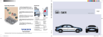
I N S T R U K T I O N S B O K V O LV O X C 9 0
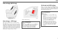
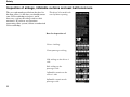
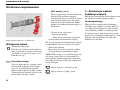
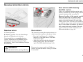
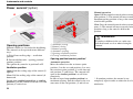
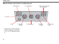
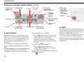
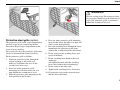
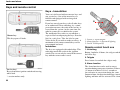
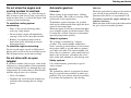
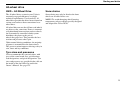
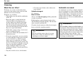
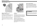
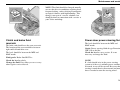
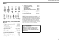
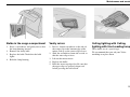
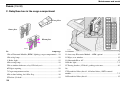
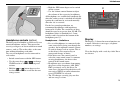
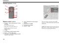
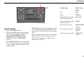
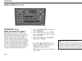
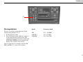
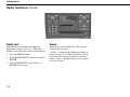
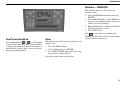
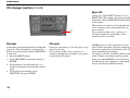
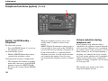
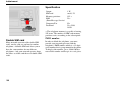
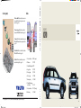
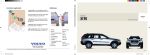
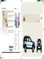
Glödlampor
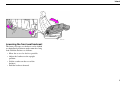
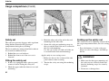
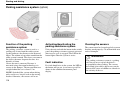
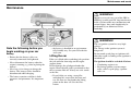
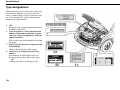
Kontrollera regelbundet
1. Spolarvätska. Se till att behållaren alltid är
välfylld. På vintern med frostskydd! Se sidan 142.
2. Servostyrning. Nivån skall ligga mellan MINoch MAX markeringarna. Se sidan 143.
10
3. Kylvätskan. Nivån skall ligga mellan MINoch MAX markeringarna på expansionstanken.
Se sidan 142.
9
8
7
6
4. Oljenivån. Nivån skall ligga mellan markegarna på mätstickan. Se sidan 141.
5. Bromsvätskenivån. Nivån skall ligga mellan
MIN- och MAX markeringarna. Se sidan 141.
1 2 34 5
3
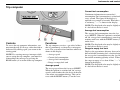
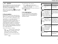
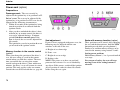
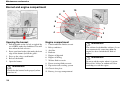
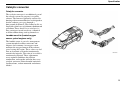
1. Blinker
H21W (orange)
2. Helljus
55W H7
VOLVO
XC90
WEB EDITION
3. Positions/parkeringsljus W5W
4. Halvljus
55W H7
5. Dimstrålkastare
55W H1
6. Dimljus, bak
21W BA5
7. Backljus
21W BA15
8. Positions/parkeringsljus
och bakljus
P21 4W
PY21W (orange)
10. Bromsljus
21W BA15
TP 6749
TP 6749 (Swedish) AT0346 3.300.10.03 Printed in Sweden, T Elanders Graphic Systems AB, Göteborg 2003
9. Blinker
2004
52930 XC90 Svensk.indd 1
2003-09-12, 07.09.41
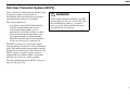
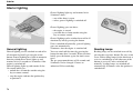
Volvo Service
Certain service measures, which affect the car’s electrical system, can only be carried out using electronic equipment
specially developed for your car. Always contact your Volvo workshop before beginning or carrying out service work
which affects the electrical system.
Installing accessories
Incorrect connection and installation of accessories can negatively affect the car’s electrical system. Certain accessories only function when the appropriate software has been programmed into the car’s electrical system. Always
contact your Volvo workshop before installing accessories which are connected to or affect the electrical system.
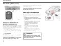
Recording vehicle data
One or several of the computers in your Volvo are capable of recording detailed information which may include
specific – without being limited to – details regarding; frequency of seat belt use by the driver and passenger, information on various vehicle system/module functions and information regarding engine, throttle, steering, brakes and
other system status.
This information may include details regarding the manner in which the driver operates the vehicle. This type of information can include specific – without being limited to – details regarding vehicle speed, use of the brakes, accelerator
pedal or steering wheel position. This information can be stored while the car is being driven, during a collision or a
near-collision.
The stored information may be read and used by:
•
•
•
•
Volvo Car Corporation
Service and repair facilities
Police and other authorities
Other interested parties who are entitled – or receive your permission for – access to this information.
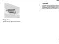
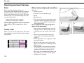
Introduction
Contents
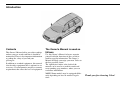
This Owner’s Manual offers you advice and tips
on how your car works and how it should be
maintained. There is also important information
regarding the safety of you and your
passengers.
In addition to standard equipment, this manual
also describes equipment that is optional or an
accessory. Certain countries may have statutory
requirements that affect the level of equipment.
The Owner’s Manual is used as
follows
Use this Owner’s Manual to better acquaint
yourself with the functions of the car and to
look for specific information. The Owner’s
Manual will help you enjoy your new Volvo to
the best possible extent.
The alphabetical index at the back of the
manual can be used to search for words and
corresponding page numbers, where you can
read more information.
127(Some models may be equipped differently depending on local or national regulations.
7KDQN\RXIRUFKRRVLQJ9ROYR
1
The specifications, design features and illustrations in this Owner’s Manual are not binding.
We reserve the right to make modifications
without prior notice.
©Volvo Car Corporation
2
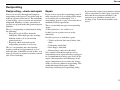
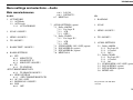
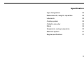
Contents
Safety
Instruments and controls
Climate control
Interior
Locks and alarm
Starting and driving
Wheels and tyres
Car care
Maintenance and service
Infotainment
Specifications
Alphabetical index
9
29
53
67
87
97
121
129
135
159
203
213
3
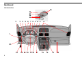
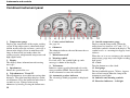
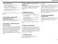
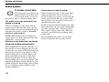
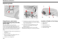
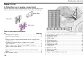
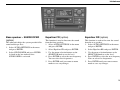
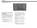
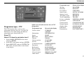
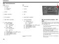
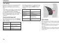
Dashboard
Left-hand drive
25
26
27
28
29
2
3
4
5
6
7 8 9 10 11
12
1
24
23
4
22 21 20 19 18
17
16
15
14
13
1.
2.
3.
4.
5.
6.
7.
8.
9.
10.
11.
12.
13.
14.
15.
16.
17.
18.
19.
20.
21.
22.
23.
Lighting panel
Air vent
Display
Temperature gauge
Odometer/Trip odometer/
Cruise control
Speedometer
Direction indicators
Tachometer
Outside temperature/Clock/
Gear position
Fuel gauge
Indicator and warning
symbols
Air vents
Glovebox
Hazard warning flashers
Audio system
Climate control
Windscreen wipers
Telephone/Audio keypad
Combined instrument panel
Horn
Cruise control
Direction indicators/Beam
selection/Read button
Parking brake
3DJH
38
55
35
30
30
30
30
30
30
30
24.
25.
26.
27.
28.
29.
30.
31.
Parking brake release
Reading lamp buttons
Interior lighting
Sunroof control
Seat belt reminder
Rearview mirror
Lock button for all doors
Blocking power windows in
the rear doors
32. Power window controls
33. Door mirror control
45
74
74
50
33
49
90
30 31
32
33
47
47
49
&RQWUROSDQHOLQWKHGULYHU¶VGRRU
31
55
77
42
165
56, 60
40
162
30
4
44
39, 35
45
5
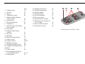
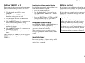
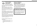
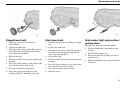
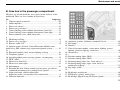
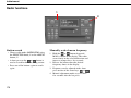
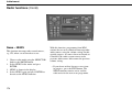
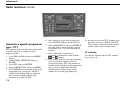
Right-hand drive
25
26
27
28
29
12
11 10 9
8 7
6 5 4
3
2
1
13
6
14 15 16 17 18 19 20
21 22
23
24
1. Lighting panel
2. Air vent
3. Indicator and warning
symbols
4. Fuel gauge
5. Outside temperature/Clock/
Gear position
6. Tachometer
7. Direction indicators
8. Speedometer
9. Odometer/Trip odometer/
Cruise control
10. Temperature gauge
11. Display
12. Air vents
13. Glovebox
14. Hazard warning flashers
15. Audio system
16. Climate control
17. Direction indicators/Beam
selection/Read button
18. Parking brake
19. Cruise control
20. Horn
21. Combined instrument panel
22. Telephone/Audio keypad
3DJH
38
55
31
30
30
30
30
30
30
30
35
55
77
42
165
56, 60
23.
24.
25.
26.
27.
28.
29.
30.
31.
Windscreen wipers
Parking brake release
Reading lamp buttons
Interior lighting
Sunroof control
Seat belt reminder
Rearview mirror
Lock button for all doors
Blocking power windows in
the rear doors
32. Power window controls
33. Door mirror control
40
45
74
74
50
33
49
90
30 31
32
33
47
47
49
&RQWUROSDQHOLQWKHGULYHU¶VGRRU
39, 35
45
44
6
30
162
7
8
Safety
Seat belts
10
Airbags (SRS)
12
Side airbags (SIPS bag)
15
Roll-Over Protection System (ROPS)
17
Inflatable Curtain (IC)
18
WHIPS
19
When are the safety systems activated?
21
Inspection of airbags, inflatable curtains and
seat belt tensioners
22
Child safety
23
9
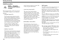
Safety
Seat belts
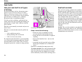
Use your seat belt for all types
of driving
Seat belt reminder
The seat belt warning symbol in the combined
instrument panel and above the rearview mirror
flashes until the driver and front seat passenger
put on their seat belts. The seat belt reminder
switches off after 6 seconds if speed is lower
than 10 km/h. If the driver or front seat
passenger have not put on their seat belts, the
reminder switches on if speed exceeds 10 km/h
and switches off if speed drops below 5 km/h. If
you take off your belt, the function reactivates
when speed exceeds
10 km/h.
Even hard braking can have dangerous consequences if you are not wearing a seat belt!
Always ask your passengers to use seat belts!
Otherwise, rear seat passengers may be thrown
into the front seat backrests in a collision.
Everyone in the car could then be hurt.
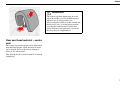
Use the seat belt as follows: pull the belt out
slowly and secure it by inserting the locking tab
into the lock. A loud "click" indicates that the
belt is locked.
The belt is not normally restricted and you can
move freely.
The belt is restricted and cannot be pulled out
further...
• ...if it is pulled out too fast
• ...during braking and acceleration
• ...if the car leans excessively
It is important that the belt lies against the body
so it can provide maximum protection. Do not
lean the backrest too far back. The seat belt is
designed to protect in a normal seating position.
([WHQGLQJWKHODSEHOW
Keep in mind the following:
• do not use clips or anything else that
prevents the belt from lying correctly.
• ensure the belt is not twisted or caught on
anything.
• the lap belt should sit low - not over the
abdomen.
• stretch the lap belt over the lap by pulling
the diagonal shoulder belt as illustrated
above.
Each belt is intended for RQH person only!
7RUHOHDVHWKHEHOW Press the red button in the
lock and allow the reel to pull the belt in. If it
does not pull in the belt completely, feed the
belt in manually so that it does not hang loose.
10
127(The seat belt reminder is intended for
an adult sitting in the front seat. If a belt-fitted
child seat is fitted in the front seat, the seat belt
reminder does not switch on.
Safety
Seat belts and seat belt
tensioners
All seat belts are equipped with seat belt
tensioners. A small mechanism, built into the
seat belt reel, triggers at the moment of impact
to tension the belt around the body and reduce
slack from clothing, etc. The belt thus restrains
the passenger more quickly.
0DUNLQJRQVHDW
EHOWVZLWKVHDWEHOW
WHQVLRQHUV
Pregnant women
Pregnant women should be especially careful
when using seat belts! Always remember to
position the belt so that there is no unnecessary
pressure on the womb. The lap belt of the threepoint seat belt should be low.
WARNING!
If the seat belt has been subjected to large
stresses, such as in a collision, the entire seat
belt assembly including reel, mountings,
bolts and lock must be replaced. Even if the
belt appears undamaged, some of the
protective properties may have been lost.
Replace the seat belt if it is worn or
damaged.
1HYHU make any modifications or repairs to
the seat belt yourself. Let an authorised
Volvo workshop perform this work.
11
Safety
Airbags (SRS)
/HIWKDQGGULYH
5LJKWKDQGGULYH
/RFDWLRQRIIURQWSDVVHQJHUDLUEDJ
Driver’s airbag
Front passenger airbag
To further increase interior safety, your car is
equipped with an airbag (SRS1) as a
complement to the three-point seat belt. The
inflatable airbag is installed folded up in the
centre of the steering wheel. The wheel is
marked SRS.
The airbag on the passenger side is folded up in
a compartment above the glovebox. The panel
is marked SRS. The volume of the inflated
airbag is approximately 140 litres.
When the airbag is inflated, its volume is
approx. 60 litres. The volume of the driver’s
airbag is less than that of the airbag on the
passenger side.
1. Supplemental Restraint System
(SRS)
12
WARNING!
Do not attach clips or any other equipment
to the dashboard or steering wheel!
This can result in injury and/or compromise
the intended protection of the airbag when it
is inflated.
WARNING!
Airbags (SRS) are designed to provide
additional protection and do not replace seat
belts. For maximum safety:$OZD\VXVHD
VHDWEHOW.
Safety
WARNING!
$LUEDJ±SDVVHQJHUVLGH
• 1HYHU put a child seat or booster
cushion in the front seat if the car is
equipped with an airbag (SRS) on the
passenger side.
• 1HYHU allow a child to stand or sit in
front of the front passenger seat.
• 1RRQH shorter than 140 cm should sit
in the front passenger seat.
• Passengers should sit as upright as
possible with their feet on the floor
and backs against the backrests. Seat
belts should be secured.
• No objects or accessories may be
positioned or stuck on or near the SRS
panel (above the glovebox) or in the
area affected by the airbag.
• Do not place loose objects on the
floor, seat or dashboard.
• Never interfere with SRS components
in the steering wheel hub or the panel
above the glovebox.
WARNING!
If the SRS warning lamp remains lit or lights
while driving, it means that the SRS system
is not functioning fully. Contact an
authorised Volvo workshop.
Warning lamp in the combined
instrument panel
The sensor/control module continuously
monitors the SRS system and there is a warning
lamp in the combined instrument panel. This
lamp lights when the ignition key is turned to
position I, II or III. The lamp goes out when the
sensor/control module has checked that the SRS
system is fault-free. This normally takes about
7 seconds.
13
Safety
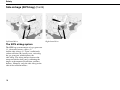
Airbags (SRS) (Contd)
Volvo Dual-Stage Airbag
(Dual-stage airbags)
If a collision is mild but sufficiently violent that
there is a risk of personal injury, the airbags are
partially inflated. If the collision is more severe,
the airbags are inflated fully.
WARNING!
656V\VWHPOHIWKDQGGULYH
656V\VWHPULJKWKDQGGULYH
SRS System
127(The sensor (3) reacts differently
depending on the severity of the collision and
whether the driver or passenger side seat belts
are in use. Crash situations may occur where
only one airbag is deployed. Never buckle the
front passenger seat belt into the driver’s side
belt buckle!
The system consists of a gas generator (1)
surrounded by the inflatable airbag (2). Upon a
sufficiently violent collision, a sensor (3) reacts,
activating the gas generator ignitor and the
airbag inflates as it heats up. To cushion the
impact, the airbag deflates when compressed.
When this occurs, smoke escapes into the car.
This is completely normal. The entire process,
including inflation and deflation of the airbag,
occurs in tenths of a second.
14
The SRS system senses the collision in the level
of braking and speed reduction caused by the
collision. The sensors determine if the collision
is of the character and nature requiring airbag
deployment to protect the occupants.
1HYHU try to repair any part of the SRS or
SIPS bag systems yourself. Any interference
in the system could cause malfunction and
serious injury. Any work should only be
performed by an authorised Volvo
workshop.
Safety
Side airbags (SIPS bag)
Child seat and SIPS airbag
If the car is only equipped with SIPS airbags
and does not have a front airbag (SRS) on the
passenger side, child seats/booster cushions can
be located in the front seat.
WARNING!
,QIODWHG6,36DLUEDJ
Side airbags – SIPS bags
Side airbags further increase interior safety.
The SIPS airbag system consists of two main
components: side airbags and sensors. The side
airbags are installed in the frames of the front
seat backrests and the sensors are located in the
insides of the centre pillars. The volume of an
inflated side airbag is about 12 litres.
WARNING!
Side airbags (SIPS bags) are an addition to
the existing SIPS system (Side Impact
Protection System). For maximum
protection:$OZD\VXVHDVHDWEHOW.
6,36DLUEDJ
• Never interfere with the SIPS airbag
system.
• Extra seat covers must not be used on
the front seats if they are not Volvo
Genuine covers or Volvo approved
seat covers for SIPS airbags.
• No objects or accessories may be
placed between the outer side of the
seat and the door panel because this
area may be affected by the SIPS
airbag.
15
Safety
Side airbags (SIPS bag) (Contd)
/HIWKDQGGULYH
The SIPS airbag system
The SIPS bag system consists of a gas generator
(1), electronic sensors, cables (3)
and the side airbags (2). Upon a sufficiently
violent collision, the sensors react, activating
the gas generator, which inflates the
side airbag. The airbag inflates between the
occupant and the door panel, cushioning the
impact at the moment of collision, and then
deflates. Normally, only the side airbag on the
side of the collision inflates.
16
5LJKWKDQGGULYH
Safety
Roll-Over Protection System (ROPS)
Volvo’s Roll-Over Protection System has been
designed to reduce the risk of the car
overturning and to provide the best possible
protection in the event of an accident.
The system consists of:
• A stabiliser system, RSC (Roll Stability
Control) that minimises the risk of
overturning during sudden evasive
manoeuvres or the like or if the car skids.
• Increased protection for the driver and
passengers through a reinforced body,
inflatable curtains and seat belt tensioners
in all seats. See page 11 and page 18.
The RSC system uses a gyro sensor which
registers changes in the car’s lateral inclination
angle. This information is then used to calculate
the risk for overturning. If a risk is detected, the
DSTC system is engaged, engine speed is
reduced and one or more wheels are braked
until the car returns to a stable position.
WARNING!
Under normal driving conditions, the RSC
system improves the car’s road safety, but
this should not be taken as a reason to
increase speed. Always follow the usual
precautions for safe driving.
For more information on the DSTC system, see
page 34 and page 108.
17
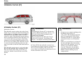
Safety
Inflatable Curtain (IC)
Inflatable Curtain (IC)
(Inflatable Curtain)
The inflatable curtain reduces the risk of head
injuries by preventing the head from hitting the
inside of the car and protecting against objects
with which the car collides, such as another
vehicle or a pole. The inflatable curtain protects
those travelling in both the front and outer rear
seats. It also prevents passengers from being
completely or partially thrown from the car in
the event of an accident. The inflatable curtain
is concealed in the headlining and covers the
upper part of the car interior at the front and rear
seats.
The inflatable curtain may be activated when
the car is hit from the side, overturns or rolls.
The curtain then fills with gas from the gas
generator, which is located in the rear of the
curtain.
18
WARNING!
The Inflatable Curtain (IC) is designed to
provide additional protection, not as a seat
belt replacement. For maximum safety:
$OZD\VXVHVHDWEHOWV.
Keep in mind that the Inflatable Curtain
protects the occupant’s head from side
impact – not impacts occurring from above.
In Volvo XC90, the inflatable curtains have
been further developed to protect occupants in
the event of overturning. The curtain also
covers those travelling in the third row of seats
in the variant that seats seven.
WARNING!
• Do not screw or mount anything to the
headlining, door pillars or
side panels. The intended protection
may be compromised. Only Volvo
Genuine parts that are approved for
placement in these areas should be
used.
• If the rear seat backrests are lowered,
do not load higher than the bottom
edge of the side windows. Leave 10
cm free space from the window
inwards. Otherwise, the intended
protection of the inflatable curtain
hidden in the headlining may be
compromised.
Safety
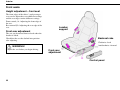
WHIPS
Whiplash Protection System
Correct seating position
WHIPS and child seat
This system consists of energy absorbing
backrests and specially developed head
restraints in both front seats.
For the best possible protection, you and your
front seat passenger should sit in the centre of
your seats with as little distance as possible
between the head restraints and your heads.
The WHIPS system does not negatively affect
the protective properties of the car with regard
to child seats. As long as there is no airbag
(SRS) on the passenger side, a Volvo child seat
may be located in the front passenger seat. The
WHIPS system still functions if a rear-facing
child seat is placed on the rear seat and
supported against the front seat backrest.
WHIPS seat
WHIPS is activated upon a collision from
behind based on the collision angle, speed and
nature of the colliding vehicle. Upon activation,
the backrests of the front seats, if occupied,
move backward and the seating position of the
occupants in the front seats is altered. This
diminishes the risk of whiplash injury.
WARNING!
WHIPS is designed to provide additional
protection and does not replace seat belts.
For maximum safety:$OZD\VXVHDVHDW
EHOW.
19
Safety
WHIPS (Contd)
WARNING!
Be sure to never hinder the function of the
WHIPS system!
• If a rear backrest is folded down, the
corresponding front seat must be
adjusted so that it is not in contact
with the folded backrest.
• Avoid placing boxes or similar cargo
so that it is clamped between the seat
cushion of the rear seat and the
backrest of the front seat.
20
WARNING!
If the seat has been exposed to a heavy load
strain, such as in a rear-end collision, the
WHIPS system should be inspected by an
authorised Volvo workshop. Even if the seat
does not appear damaged, the WHIPS
system may have deployed without causing
visible damage to the seat. The protective
capacity of the WHIPS system may be
impaired. Have the system checked at an
authorised Volvo workshop even after
minor rear-end collisions. Never modify or
repair the seat or WHIPS system yourself!
Safety
When are the safety systems activated?
System
Triggered
Seat belt tensioner
In the event of a head-on collision or overturning. The belt is tensioned around the body to reduce slack from clothing,
etc. The belt thus restrains the passenger more quickly.
In collisions if there is a risk that front seat passengers could be injured by hitting the dashboard or steering wheel.
In side-on collisions if the car is hit with sufficient force.
In side-on collisions or if the car overturns. The curtain reduces the risk of head injuries.
When hit from behind. Reduces the risk of neck injuries, i.e. whiplash.
During sudden evasive manoeuvres or the like or if the car skids. Reduces the risk of overturning.
Airbags (SRS)
Side airbags
Inflatable Curtain (IC)
WHIPS
RSC
WARNING!
WARNING!
The SRS system sensor is located in the
centre console. If the floor of the passenger
compartment has been drenched with water,
disconnect the battery cables in the cargo
compartment. Do not try to start the car; the
airbags may deploy. Have the car towed to
an authorised Volvo workshop.
Never drive with deployed airbags! This
may make the car difficult to steer. Other
safety systems may also be damaged.
Intense exposure to the smoke and dust
released when the air bags are deployed can
cause skin and eye irritation. In case of
problems, wash with cold water and contact
a doctor. The speed of the deployment and
the airbag fabric may cause friction burns on
the skin.
127(The SRS, SIPS and IC systems are only
deployed once in a collision. If the airbags have
been deployed, we recommend the following:
• Tow the car to a Volvo workshop. Do not
drive the car with the airbags deployed
even if the car can be driven after an
accident.
• Let an authorised Volvo workshop
replace components in the SRS, SIPS,
and IC systems.
The bodywork of the car could be greatly
deformed in a collision without airbag
deployment. This does not indicate a fault in the
airbags. This means that the function was not
needed at that moment and the occupants were
protected by the other safety systems of the car.
21
Safety
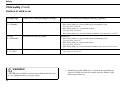
Inspection of airbags, inflatable curtains and seat belt tensioners
The year and month specified on the decal in
the door pillar(s) is the date you should contact
your Volvo workshop to inspect, and if
necessary, replace the airbags and seat belt
tensioners. If you have any questions
concerning either system, contact an authorised
Volvo workshop.
7KLVGHFDOLVORFDWHGLQWKH
UHDUOHIWGRRURSHQLQJ
'DWHIRULQVSHFWLRQRI
'ULYHU¶VDLUEDJ
)URQWSDVVHQJHUDLUEDJ
6LGHDLUEDJRQWKHGULYHU¶V
VLGH
6LGHDLUEDJRQWKH
SDVVHQJHUVLGH
,QIODWDEOHFXUWDLQRQWKH
GULYHU¶VVLGH
,QIODWDEOHFXUWDLQRQWKH
SDVVHQJHUVLGH
22
Safety
Child safety
Children should sit comfortably
and safely
Child seat and seat belt
reminder
Remember that children, regardless of age or
size, should always be securely strapped into
the car. Never allow a child to sit on the knee of
a passenger!
If a rear-facing infant or child seat is placed in
the front seat and secured using the seat belt, the
seat belt reminder might not be activated.
Always check that the belt is locked before
driving off!
The weight and height of the child must be
taken into consideration when selecting
equipment and its location. See page 24.
Volvo’s own child safety equipment is designed
for your car. If you select Volvo equipment, you
can be sure that the mounting points and attachments are correctly positioned and sufficiently
strong.
Children up to 3 years of age sit safest in a rearfacing child seat.
127(Many countries have regulations
regarding where children should be located in
the car. Find out what laws apply in the
countries you will be visiting.
WARNING!
Never put a child seat/booster cushion in the
front seat if the car is equipped with SRS
(airbag) on the passenger side.
$LUEDJVDQGFKLOGVHDWVDUHQRWFRPSDWLEOH
Child seat and airbag
If the car has a passenger airbag, the child seat
must be placed in the rear seat.
If seated in a child seat in front of a passenger
airbag and the airbag inflates, the child could be
seriously injured.
Passengers shorter than 140 cm must QHYHU sit
in the front passenger seat if the car has a
passenger airbag.
23
Safety
Child safety (Contd)
Position of child in car
Weight/age
Front seat with passenger airbag*
Front seat without passenger airbag (option)
<10 kg
(0 –9 months)
Not suitable for this age group.
Alternatives:
•
•
•
9–18 kg
(9 –36 months)
Not suitable for this age group.
Rear-facing child seat, secured with seatbelt and mounting strap.
7\SHDSSURYDO(
Rear-facing infant seat, secured with seatbelt.
7\SHDSSURYDO(
Rear-facing infant seat, secured in Isofix attachment. 7\SHDSSURYDO(
Alternatives:
• Rear-facing child seat, secured with seatbelt and mounting strap.
7\SHDSSURYDO(
• Rear-facing child seat, secured with seatbelt.
7\SHDSSURYDO(
• Rear-facing child seat, secured in Isofix attachment. 7\SHDSSURYDO(
15 –36 kg
(3 –12 years)
Not suitable for this age group.
WARNING!
* NEVER place a child seat or booster cushion in the front seat
of a car equipped with a passenger airbag.
24
• Booster cushion with or without backrest.
7\SHDSSURYDO(
1. Suitable for certain child seats as listed in the specified type
approval. Child seats may be vehicle-specific, limited, semiuniversal or universal.
Safety
Weight/age
Second row of seats, outer seats*
<10 kg
(0 –9 months)
Alternatives:
9–18 kg
(9 –36 months)
Alternatives:
15 –36 kg
(3 –12 years)
• Rear-facing child seat, secured with seatbelt, support and
mounting strap.7\SHDSSURYDO(
• Rear-facing infant seat, secured with seatbelt and
support. 7\SHDSSURYDO(
• Rear-facing infant seat, secured with Isofix attachment
and support. 7\SHDSSURYDO(
• Rear-facing child seat, secured with seatbelt, support and
mounting strap.7\SHDSSURYDO(
• Rear-facing child seat, secured with seatbelt and support.
7\SHDSSURYDO(
• Rear-facing child seat, secured with Isofix attachment
and support. 7\SHDSSURYDO(
• Booster cushion with or without backrest.
7\SHDSSURYDO(
1. Suitable for certain child seats as listed in the specified type
approval. Child seats may be vehicle-specific, limited, semiuniversal or universal.
2. Integrated and approved child safety equipment for this age
group.
*In cars seating seven, the seat row must be in its rearmost
position when using a child seat.
Second row of seats,
centre seat*
Third row of seats in cars
seating seven.
• Rear-facing child seat,
Not suitable for this age group.
secured with seatbelt, support
and mounting strap.
7\SHDSSURYDO(
• Rear-facing child seat,
Not suitable for this age group.
secured with seatbelt, support
and mounting strap.
7\SHDSSURYDO(
Alternatives:
• Booster cushion with or
without backrest.
7\SHDSSURYDO(
• Integrated booster cushion.
7\SHDSSURYDO(
• Booster cushion with or without
backrest.
7\SHDSSURYDO(
WARNING!
NEVER place a child seat or booster cushion in the front seat of
a car equipped with a passenger airbag.
25
Safety
Child safety (Contd)
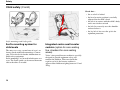
&KHFNWKDW
• the seat belt is locked
• the head restraint position is carefully
adjusted for the child’s head
• the belt is in contact with the child’s body
and is not slack or twisted
• the belt lies correctly over the shoulder
and not below it
• the lap belt is low over the pelvis for
optimum protection.
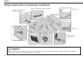
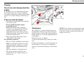
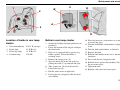
,VRIL[PRXQWLQJVDQG,VRIL[JXLGH
IIsofix mounting system for
child seats
The outer rear seats (second row of seats) are
factory fitted with Isofix mountings. Contact
your Volvo dealer for further information on
child safety equipment.
Isofix mountings are located in both outer rear
seats. The Isofix guide can be moved from one
side to the other as needed.
26
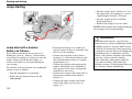
Integrated centre seat booster
cushion (option for cars seating
five, standard for cars seating
seven)
Volvo’s integrated booster cushion is specially
designed to provide optimum safety and
comfort for children. When used with the
regular seat belt, the booster cushion is
approved for children weighing between 15 and
36 kg.
Safety
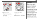
WARNING!
If an integrated booster cushion has been
subjected to great stress, such as in a
collision, the entire booster cushion,
including the seat belt and bolts, must be
replaced. Even if the integrated booster
cushion appears undamaged, it may not
afford the same level of protection.
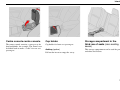
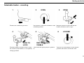
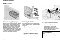
5DLVLQJWKHERRVWHUFXVKLRQ
/RZHULQJWKHERRVWHUFXVKLRQ
1. Pull that handle to raise the booster
cushion.
2. Grasp the cushion with both hands and
moveit rearwards.
3. Move the seat belt buckle aside; press the
cushion until it locks in place.
1. Pull the handle.
2. Move the seat down and press until it
locks.
Remember to first stow the booster cushion if
you wish to lower the seat’s backrest.
The booster cushion should also be replaced
if it is worn or damaged. Note, however, that
the cushion should only be replaced by a
professional as it is vital for passenger safety
that the booster cushion is correctly
installed. Therefore, replacement and any
repairs to the cushion should be referred to
an authorised Volvo workshop.
If the cushion becomes dirty, try to clean it
in situ. If the upholstery is so dirty that it
needs to be washed separately, the instructions provided above for replacing and
installing the cushion should be followed.
Do not modify or adapt the booster cushion
in any way.
27
Safety
Child safety (Contd)
Important tips!
When using other child safety products that are
available on the market, it is LPSRUWDQW to read
the installation instructions that accompany the
product and follow them carefully. Here are
some points you should consider:
• Volvo has child safety products that are
designed for and tested by Volvo.
• The child seat must always be placed
according to the manufacturer’s directions. See the child seat instruction
manual for further installation instructions.
• Do not attach the child seat straps to the
horizontal adjustment bar, springs or any
of the rails and struts under the seat that
may have sharp edges.
• Allow the backrest of the child seat to rest
against the dashboard (Applies to cars
ZLWKRXW an airbag (SRS) on the passenger
side).
• Never place a child seat in the front seat if
the car is equipped with an airbag (SRS)
on the passenger side.
28
127(If there are any problems with installation of child safety products, contact the
manufacturer for clearer installation instructions.
WARNING!
Support cushions/child seats with steel frames
or another design that can lie against the
seatbelt release button must not be used because
they can cause accidental release of the seatbelt. Do not allow the top of the child seat to rest
against the windscreen.
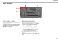
Instruments and controls
Combined instrument panel
30
Indicator and warning symbols
31
Switches in the centre console
36
Lighting panel
38
Direction indicator lever
39
Windscreen wipers/washer
40
Hazard warning flashers, rear window and door
mirror defrosters, heated front seats
42
Trip computer
43
Cruise control
44
Parking brake, bonnet, electric socket, etc.
45
Power windows
47
Rearview mirror/door mirrors
49
Power sunroof (option)
50
29
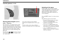
Instruments and controls
Combined instrument panel
7HPSHUDWXUHJDXJH
Displays the temperature of the engine cooling
system. If the temperature is abnormally high
and the needle enters the red zone, a message is
shown in the display. Bear in mind that extra
lamps in front of the air intake reduce the
cooling capacity at high outside temperature and
high engine loads.
'LVSOD\
The display shows information and warning
messages.
6SHHGRPHWHU
Shows the speed of the car.
7ULSRGRPHWHUV7DQG7
The trip odometers are used for measuring short
distances. The right-hand digit displays tenths
of a kilometre. Press the button for more than 2
seconds to reset. Change between trip
odometers by briefly pressing the button once.
30
&UXLVHFRQWUROLQGLFDWRU
See page 44.
2GRPHWHU
The odometer indicates the total distance the car
has travelled.
0DLQEHDPRQRII
:DUQLQJV\PERO
If a fault arises, the symbol lights up and a
message is shown in the display.
7DFKRPHWHU
Indicates engine speed in thousands of revolutions per minute (RPM). Do not allow the needle
of the tachometer to enter the red field.
$XWRPDWLFJHDUER[LQGLFDWRU
The selected gearshift programme is displayed
here.
2XWVLGHWHPSHUDWXUHJDXJH
Displays outside temperature. When the
temperature lies between +2°C and –5°C, a
snowflake symbol is shown in the display. This
symbol serves as a warning for slippery road
surfaces.
When the car is or was stationary, the outside
temperature gauge may read a higher reading
than actual.
&ORFN
Turn the button to set the clock.
)XHOJDXJH
The fuel tank holds approx. 70 litres. Approx. 8
litres of fuel remain when the lamp in the
instrument panel lights.
,QGLFDWRUDQGZDUQLQJV\PEROV
'LUHFWLRQLQGLFDWRUV±OHIWULJKW
Instruments and controls
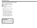
Indicator and warning symbols
Fault in the ABS system
If the ABS symbol lights, the ABS
system is malfunctioning. The car’s
normal braking system continues to work, but
without the ABS function.
• Stop the car in a safe place and switch off
the engine. Restart the engine.
• If the warning symbol goes out, continue
driving. It was an indicator error.
• If the warning symbol remains lit, drive
to an authorised Volvo workshop to have
the ABS system checked.
Fault in braking system
The indicator and warning symbols light when
you turn the ignition key to the driving position
(position II) before starting. This shows that the
symbols are functioning. When the engine is
started, all symbols go out. If the engine is not
started within 5 seconds, all symbols except
and
go out. Certain symbols may not
have the function indicated, depending on the
car’s equipment. The symbol for the parking
brake goes out when the parking brake is
released.
Warning symbol
dashboard
in centre of
The symbol lights with a red or orange glow
depending on the severity of the fault.
Red symbol:
Orange symbol:
Stop the car. Read the
message in the display.
Read the message in the
display. Remedy!
If the BRAKE symbol lights, the brake
fluid level may be too low.
• Stop the car in a safe place and check the
brake fluid reservoir level.
• If the reservoir level is below MIN, the
car should not be driven further. Have it
towed to an authorised Volvo workshop
to have the brake system checked.
31
Instruments and controls
Indicator and warning symbols (Contd)
If the %5$.( and $%6 warning
symbols light at the same time, there
may be a problem in the brake force
distribution.
•
•
•
•
•Stop the car in a safe place and
switch off the engine. Restart the
engine.
If both symbols go out, it was an indicator
error.
If the warning symbols remain lit, check
the brake fluid reservoir level.
If the reservoir level is below MIN, the
car should not be driven further. Have it
towed to an authorised Volvo workshop
to have the brake system checked.
If the brake fluid level is normal and the
lamps remain lit, carefully drive the car to
the nearest authorised Volvo workshop to
have the brake system checked.
WARNING!
If the BRAKE and ABS warning symbols
light at the same time, there is a risk that the
rear end will have a tendency to slide during
heavy braking.
32
Instruments and controls
Seat belt reminder
Fault in SRS
Parking brake applied
The lamp remains lit until the driver and
front seat passenger put on their seat belts.
If the symbol remains lit or lights while
driving, a fault has been detected in the
SRS system. Drive to an authorised Volvo
workshop to have the system checked.
Bear in mind that the lamp only indicates
that the parking brake is applied, not
how hard. Check by depressing the
pedal! If the pedal is set when driving, a
signal will be heard as a reminder.
Low oil pressure
Generator not charging
Rear fog lamp
If the lamp lights while driving, engine oil
pressure is too low. Stop the engine
immediately and check the oil level. If the
lamp lights but the oil level is normal,
stop the car and contact an authorised
Volvo workshop.
If this lamp lights while driving, there is
probably a fault in the electrical system.
Contact an authorised Volvo workshop.
This lamp lights when the fog lamp is on.
Fault in emissions system
Engine preheater (diesel)
Trailer indicator lamp
Contact an authorised Volvo workshop to
have the system checked.
This lamp lights to indicate that the engine
is being preheated. You can start the car
when the lamp goes out. Applies to cars
with disel engines only.
Flashes when the direction indicators of
the car and trailer are used. If the lamp
does not flash, one of the direction
indicators on the trailer or car is
defective.
33
Instruments and controls
Indicator and warning symbols (Contd)
DSTC with RSC
The DSTC system (Dynamic Stability and
Traction Control) with RSC (Roll Stability
Control) is described in more detail on page 36
and page 108. The system comprises several
different functions:
Reduced traction control
This symbol lights and shines with a constant
glow when the DSTC system has reduced
function due to high brake temperature. The
text "TRACTION CONTROL TEMPORARILY OFF" is shown in the display.
Reduced stability control
The LED in the button goes out when function
of the DSTC system has been reduced with the
DSTC button in the centre console. The text
"DSTC SPIN CONTROL OFF" is shown in the
display.
Fault in DSTC system
If the warning symbol lights and shines with a
constant glow even though you did not switch
off the system, it indicates a fault in one of the
systems. The text "ANTI-SKID SERVICE
REQUIRED" is shown in the display.
34
• Stop the car in a safe place and switch off
the engine. Restart the engine.
• If the warning symbol goes out, the fault
was temporary and it is not necessary to
visit a workshop.
• If the warning symbol remains lit, drive
to an authorised Volvo workshop to have
the system checked.
WARNING!
Under normal driving conditions, the DSTC
system improves the car’s road safety, but
this should not be taken as a reason to
increase speed. Always follow the usual
precautions for safe cornering and driving
on slippery surfaces.
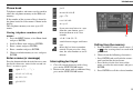
Instruments and controls
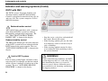
Messages in the display
Any warning or indicator symbol that appears is
accompanied by a message in the display. Once
you have read and understood the message,
press the READ button (A). Messages which
have been read are cleared from the display and
stored in the car’s memory. Fault messages will
remain in the memory until the fault has been
remedied.
9HU\VHULRXVIDXOWPHVVDJHVFDQQRWEHHUDVHG
IURPWKHGLVSOD\7KH\UHPDLQLQWKHGLVSOD\
XQWLOWKHIDXOWLVUHPHGLHG
Message
STOP SAFELY
STOP ENGINE
SERVICE URGENT
SEE MANUAL
SERVICE REQUIRED
FIX NEXT SERVICE
TIME FOR
REGULAR SERVICE
Messages stored in the memory can be read
again. Press the READ button (A) to see stored
messages. Scroll through the messages stored in
the memory by pressing the READ button.
Press the READ button to return read messages
to the memory.
127(If a warning message interrupts when
you are in the trip computer menu or wish to use
the telephone, you must first acknowledge the
message by pressing the READ button (A).
Meaning:
Stop and switch off the engine. Serious
risk of damage.
Stop and switch off the engine. Serious
risk of damage.
Take your car in for service immediately.
Consult your Owner’s Manual.
Take your car in for service as soon as
possible.
Have your car checked at the next service
interval.
When this message is shown, the car is
due for a service. When the message is
displayed is affected by the distance
travelled, number of months since last
service and engine running time.
35
Instruments and controls
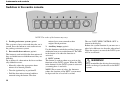
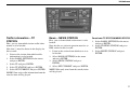
Switches in the centre console
1
2
3
4
5
6
7
8
127(7KHRUGHURIWKHEXWWRQVPD\YDU\
3DUNLQJDVVLVWDQFHV\VWHP (option)
This system is always activated when the car is
started. Press the button to activate/deactivate
the parking assistance system.
5HWUDFWDEOHGRRUPLUURUV (option)
This button is used to fold in the door mirrors if
they are folded out or to fold them out if they are
folded in.
Do as follows if a door mirror has been accidentally folded in or out:
• Manually adjust the appropriate door
mirror to its normal position.
• Turn the ignition key to position II.
• Fold the door mirror inward and then
outward using the button. The door
36
mirrors have now returned to their
original fixed positions.
$X[LOLDU\ODPSV (option)
Use this button to switch the auxiliary lamps on
with main beam or to switch them off. The LED
in the button is lit when the function is
activated.
'67&V\VWHP
This button is used to reduce or reactivate the
functions of the DSTC system. When the LED
in the button is lit, the DSTC system is activated
(assuming there is no fault).
127(For reasons of safety, the button to
reduce the function of the DSTC system must
be depressed for at least half a second.
The text "DSTC SPIN CONTROL OFF" is
shown in the display.
Reduce the system function if you must use a
wheel of a different size than the other wheels.
When the engine is restarted, the DSTC system
will be reactivated.
WARNING!
Keep in mind that the driving characteristics
of the car change if you deactivate the DSTC
system.
Instruments and controls
$LUFRQGLWLRQLQJLQWKHUHDURIWKH
SDVVHQJHUFRPSDUWPHQW(option)
Press the button to activate the air conditioning
in the rear of the passenger compartment. Rear
air conditioning is deactivated when the
ignition is completely switched off.
and use the heated coils. For reasons of safety,
always keep the cover on the socket when it is
not in use. The maximum current is 10A.
'HDFWLYDWLQJWKHGHDGORFNIXQFWLRQDQG
GHWHFWRUV
Use this button if you wish to switch off the
deadlock function (deadlock means that the
doors cannot be opened from the inside when
they are locked). This button is also used to
deactivate the movement and tilt detectors in
the alarm system. The LED lights when these
systems are deactivated.
&KLOGVDIHW\ORFNVLQWKHUHDUGRRUV
(option)
Use this button when you wish to activate or
deactivate the electric child safety locks in the
rear doors. The ignition key must be in position
I or II. When the child safety locks are
activated, the LED in the button lights. A
message is shown in the display when you
activate or deactivate the child safety locks.
(OHFWULFVRFNHW(standard)&LJDUHWWH
OLJKWHU(option)
The electric socket can be used for various 12V
accessories, such as mobile phones or coolers.
The cigarette lighter is activated by pushing in
the button . Once the lighter has been heated,
the button pops out again. Pull out the lighter
37
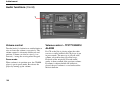
Instruments and controls
Lighting panel
A
B
C
A - Headlamps and position/
parking lamps
D - Front fog lamps
,JQLWLRQNH\LQSRVLWLRQ,, Press the button.
The fog lamps light in combination with the
position/parking lamps and main/dipped beam.
The LED in the button is lit while the fog lamps
are on.
All lighting off.
&DUVZLWKGD\WLPHUXQQLQJOLJKWV
FHUWDLQFRXQWULHV
,JQLWLRQNH\LQSRVLWLRQ,, Dipped beam
on (plus front and rear position/parking
lamps, numberplate lighting and
instrument illumination). Dipped beam
lights automatically when the ignition key
is switched to the driving position and
cannot be switched off. Before trips to
certain countries, your Volvo workshop
can help you deactivate the daytime
running lights.
Front and rear position/parking lamps.
,JQLWLRQNH\LQSRVLWLRQ All lighting
off.
,JQLWLRQNH\LQSRVLWLRQ,, Headlamps
light (plus front and rear position/
parking lamps, numberplate lighting and
instrument illumination).
127(You must always turn the light
switch to this position to switch on the
main beam.
127(In some countries, dipped beam may
not be used in combination with front fog
lamps.
E - Rear fog lamps
D
E
B - Headlamp levelling
To allow for headlamp beam adjustment to
compensate for different loads, certain cars
come equipped with an actuator motor for each
headlamp. Adjust the headlamps using the
headlamp levelling control on the dashboard.
Cars with Bi-Xenon lighting (option) have
automatic headlamp levelling.
C - Instrument illumination
Move the control upward ± brighter lighting.
Move the control downward ±dimmer lighting.
A twilight sensor (see page 60) automatically
adjusts the brightness of instrument illumination.
38
,JQLWLRQNH\LQSRVLWLRQ,,Press the button.
The rear fog lamp lights in combination with
the main/dipped beam. The LED in the button
and the symbol in the combined instrument
panel light at the same time.
3OHDVHUHPHPEHU Regulations for use of front
and rear fog lamps vary from country to
country.
Instruments and controls
Direction indicator lever
5HVLVWDQFHSRLQWSRVLWLRQ
When changing lanes or overtaking, move the
lever until you feel a distinct resistance. The
lever returns when released.
1RUPDOWXUQV
The direction indicators light when you move
the lever in the direction the wheel moves
during the turn. When the wheel returns after a
turn, the direction indicators switch off
automatically.
0DLQEHDPIODVK
Pull the lever lightly towards you (until you feel
a slight resistance). The main beam remains lit
until the lever is released.
$SSURDFKOLJKWLQJ
Do as follows when you leave your car when it
is dark out:
• Remove the key from the ignition.
• Pull the left lever (direction indicator)
towards you.
• Exit the car.
• Lock the doors.
Dipped beam, position/parking lamps, numberplate lighting and the lamps in the door mirrors
(option) now light and remain lit for 30, 60 or
90 seconds. An authorised Volvo workshop can
set a suitable duration for your car.
6ZLWFKLQJPDLQGLSSHGEHDP
Pull the lever towards you past the "flash
position" and release it to change between main
and dipped beam.
39
Instruments and controls
Windscreen wipers/washer
Rain sensor (option)
The rain sensor replaces the intermittent
function. The windscreen wipers
automatically increase or decrease speed
based on how much water the sensor
indicates is on the windscreen. 6HQVL
WLYLW\ can be adjusted using the ring (see
illustration).
To activate the rain sensor:
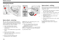
:LSHUZDVKHUIXQFWLRQ±ZLQGVFUHHQ
Windscreen wipers
Windscreen wipers off
If the lever is in the 0 position and you
move it upwards, the wipers will sweep
one stroke at a time for as long as you
hold the lever up.
Intermittent wiping
You can adjust and set a suitable speed
for intermittent wiping. Twisting the
ring (see A in illustration) upwards
increases the frequency of wiper strokes.
Twisting the ring towards you decreases
the frequency of wiper strokes.
40
• Turn on the ignition.
• Move the lever from the 0 position
to the position for intermittent wiping.
The rain sensor is deactivated when the ignition
is switched off. To reactivate the rain sensor:
• Turn on the ignition.
• Move the lever to the 0 position and then
to the position for intermittent wiping.
127(When using a car wash: Disengage the
rain sensor (move the lever to position 0) or
switch off the ignition completely. Otherwise
the windscreen wipers will begin swiping and
can be damaged.
Wipers operate at "normal" speed
Wipers operate at "high" speed
3 – Windscreen washer/
headlamp washers
Pull the lever towards the steering wheel to start
the windscreen and headlamp washers.
Headlamp washing
High-pressure washing of the headlamps
consumes vast amounts of washer fluid. To
save fluid, the headlamps are only washed
every fifth time (within a 2-minute period).
If 2 minutes have elapsed since the previous
windscreen washing, the headlamps are again
high-pressure washed then next time the
windscreen is washed.
Instruments and controls
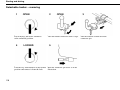
Windscreen wipers – reversing
If you engage reverse gear when the windscreen
wipers are already activated, the rear window
wipers will go into intermittent wiping mode*.
If the rear window wiper is already engaged at
normal speed, there is no change to the selected
function.
*This function (intermittent wiping when
reversing) can be switched off. Consult your
Volvo workshop.
:LSHUZDVKHUIXQFWLRQ±UHDUZLQGRZ
Rear window washer
Push the lever IRUZDUG to start the rear window
washer.
A. Rear window wiper – intermittent wiping
B. Rear window wiper – normal speed
41
Instruments and controls
Hazard warning flashers, rear window and door mirror defrosters, heated front seats
Rear window and
door mirror
defrosters
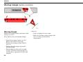
Hazard warning flashers
Use the hazard warning flashers (all direction
indicators flash) should you be forced to stop or
park where the car constitutes a possible traffic
hazard or obstruction.
3OHDVHUHPHPEHU Regulations for use of
hazard warning flashers vary from country to
country.
42
Use the defroster to
remove ice and misting
from the rear window
and door mirrors.
Pressing the switch starts
defrosting of the rear
window and door mirrors
simultaneously. The
LED in the switch lights to indicate this. A
built-in timer automatically disconnects the
defroster from the door mirrors after about 4
minutes and from the rear window after about
12 minutes.
Heated front
seats
See page 59 or 63 for
further information.
Instruments and controls
Trip computer
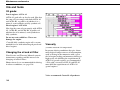
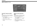
Current fuel consumption
Continuous information on current fuel
consumption. Fuel consumption is calculated
every second. The figure in the display is
updated every couple of seconds. When the car
is stationary, "----" is shown in the display.
127(The displayed value may be slightly off
if a fuel-driven heater is used.
Average fuel consumption
Controls
Functions
To access the trip computer information, you
must turn the ring (B) in steps, either forward or
backward. By turning again, you return to the
starting point.
The trip computer receives a great deal of data
that is continuously evaluated by a microprocessor. The system has four functions which are
shown in the display:
127(If a warning message interrupts while
you are using the trip computer, you must first
acknowledge the message by pressing the
READ button (A) to return to the trip computer.
• Average speed
• Current fuel consumption
• Average fuel consumption
• Range to empty fuel tank
Average speed
The average speed since the last reset (RESET).
When the ignition is switched off, the average
speed is stored and used as the basis of the new
value when you continue driving. This can be
reset with the RESET button (C) on the lever.
The average fuel consumption since the last
reset (RESET). When the ignition is switched
off, the average fuel consumption is stored and
remains until reset with the RESET button (C)
on the lever.
127(The displayed value may be slightly off
if a fuel-driven heater is used.
Range to empty fuel tank
Displays the approximate distance that can be
driven with the remaining fuel, calculated using
the average fuel consumption over the last 30
km and the remaining quantity of fuel. When
the range to empty is less than 20 km, "----" is
shown in the display.
127(The displayed value may be slightly off
if a fuel-driven heater is used.
43
Instruments and controls
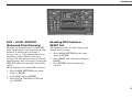
Cruise control
Temporary disengagement
Disengagement
Press to temporarily disengage the cruise
control.
Press CRUISE to switch off the cruise control.
" CRUISE " will disappear from the combined
instrument panel.
Depressing the brake or clutch pedal disengages
the cruise control. The previously set speed is
stored in the memory.
The cruise control is also temporarily disengaged when...
• the speed drops below the lower limit for
activation
• the gear selector is moved to position N
• upon a wheel spinning or locking.
Return to a speed
Activating
Press
The controls for cruise control are to the left of
the steering wheel.
Acceleration
6HWWLQJGHVLUHGVSHHG
• Press the CRUISE button. "CRUISE" is
displayed on the combined instrument
panel.
• Increase or decrease to the desired speed
by pressing + or –.
127( Cruise control cannot be engaged
at speeds under 35 km/h.
• Lightly press + or – to lock the desired
speed.
44
to resume the previously set speed.
A temporary increase in speed, e.g. during
overtaking, does not affect the cruise control
setting. The car will resume the previously set
speed. If cruise control is engaged, increase or
decrease speed with the + or – button. A short
press corresponds to approx. 1 k m/h. The speed
which the car has achieved at the time the
button is released will be programmed instead.
The cruise control is automatically disengaged
when the ignition is switched off.
127(If one of the cruise control buttons is
depressed for more than one minute, the system
will be disengaged. You must then turn the
ignition off to reset the cruise control.
Instruments and controls
Parking brake, bonnet, electric socket, etc.
2
1
3DUNLQJEUDNH/+'FDU
1
2
3DUNLQJEUDNH5+'FDU
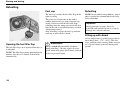
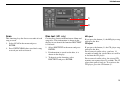
Parking brake
Opening the bonnet
The parking brake pedal is located to the left at
floor level. Apply the parking brake by
depressing the pedal (1). Release the brake by
pulling the handle (2).
Pull the handle towards you to release the
bonnet lock mechanism.
The parking brake holds the rear wheels. When
the brake is applied, the warning symbol lights
in the combined instrument panel.
Remember that the warning symbol in the
combined
instrument panel lights even if the parking
brake is only "slightly" applied.
WARNING!
Close the bonnet by placing your hand on its
top and pressing down. Do not close it by
holding the grille. Engine components on
the inside could injure your fingers.
45
Instruments and controls
Parking brake, bonnet, electric socket, etc. (Contd)
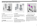
Electric socket for rear seat
passengers (option)
The electric socket can be used for various 12 V
accessories, such as mobile phones or CD
players. The maximum current is 10 A.
Steering wheel adjustment
Opening the tailgate
The steering wheel can be adjusted both vertically and front-rear. Press down the control on
the left-hand side of the steering column. Then
adjust the steering wheel to the position that
suits you best. Press the control back into place
to lock the steering wheel. If this is difficult,
press the steering wheel slightly while pressing
the control back.
Open the tailgate by pulling the handle
indicated in the illustration. Fold down the rear
flap by lifting the handle up.
WARNING!
Adjust the steering wheel before driving,
never while driving. Ensure that the steering
wheel is locked.
46
Instruments and controls
Power windows
The power windows are operated using the
controls in the door armrests. The ignition key
must be in position I or II for the power
windows to work. Once you finish driving and
remove the ignition key, the windows can still
be opened or closed as long as neither of the
front doors has been opened.
A
B
Open a window by depressing the front of the
control, and close it by pulling up the front of
the control.
Power windows in the
front doors
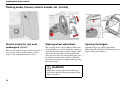
Blocking power windows in the
rear doors
Windows can be opened or closed from the
front seat two ways.
The power windows in the rear seat can be
blocked with the switch on the driver’s door
control panel. Always remember to switch off
current to the power windows (i.e. remove the
ignition key) if you leave children in the car
unattended.
1. Press the control (A) VOLJKWO\down or pull
itVOLJKWO\ up. The power windows go up or
down as long as the switch is actuated.
2. Press the control (A) DOOWKHZD\down or
pull it DOOWKHZD\up, and then UHOHDVH.
The windows then open or close automatically. Movement is stopped if the window
is blocked in any way.
127(The function DXWRXS for the passenger
side is only available in certain markets.
Controls (B) to operate windows in the rear
doors.
/('LQWKHVZLWFKLVXQOLW
Rear door windows can be operated both by the
controls on the doors and the control on the
driver’s door.
/('LQWKHVZLWFKLVOLW
Rear door windows can only be operated from
the driver’s door.
47
Instruments and controls
Power windows (Contd)
WARNING!
If rear door windows are being operated
from the driver’s door, check that no rear
seat passenger are in danger of getting
pinched when the windows close.
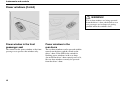
Power window in the front
passenger seat
Power windows in the
rear doors
The control for the power window at the front
passenger seat operates that window only.
The rear door windows can be operated with the
controls on the doors and the switch on the
driver’s door. If the LED in the switch for
blocking power windows in the rear doors
(located in the driver’s door control panel) is lit,
the rear door windows can only be operated
from the driver’s door.
48
Instruments and controls
Rearview mirror/door mirrors
Door mirrors with memory
function (option)
If the car is equipped with door mirrors with
memory function, they work together with the
memory function of the seat, page 70.
A
Memory function in the remote control
When you unlock the car with the remote
control and change the setting of the door
mirrors, these new settings are saved in the
remote control. The next time you unlock the
car with the same remote control and open the
driver’s door within two minutes, the mirrors
will assume their stored positions. This only
applies to the two remote controls that are
delivered with the car, page 88.
B
Rearview mirror
Door mirrors
A. Normal position.
The controls for setting the two door mirrors are
at the front of the armrest on the driver’s door.
B. Dimming position. Use this if headlamps
from the car behind you is irritating.
Certain models have an DXWRGLPfunction
(option), which means that dimming occurs
automatically based on comparative light
relationships. Your Volvo workshop can adjust
the sensitivity.
WARNING!
Adjust the mirrors before you begin driving!
• Press the L or R button (L = left door
mirror, R = right door mirror). The LED
in the button lights.
• Adjust the position with the adjustment
control in the centre. Press the button
again. The LED should no longer be lit.
Do not use ice scrapers with steel blades to
remove ice from the mirrors as the glass could
be scratched!
49
Instruments and controls
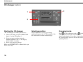
Power sunroof (option)
0DQXDORSHUDWLRQ
2SHQ Pull the control rearwards to the resistance
point position (3). The sunroof will move towards
maximum opening position as long as the control
is held in this position.
A
4
2
1
3
5
B
&ORVH Press the control forwards to the resistance
point (2). The sunroof will move towards closing
position as long as the control is held in this
position.
6
WARNING!
Opening positions
Sunroof controls are located in the headlining.
The sunroof can be operated in two different
ways:
A: Raise/lower trailing edge – ventilation
position
B: Rearwards/forwards – opening position/
comfort position*
The ignition key must be in position I or II.
Ventilation position
2SHQ Push the trailing edge of the control (5)
upward.
&ORVHPull the trailing edge of the control (6)
downward.
Switch from YHQWLODWLRQSRVLWLRQ to FRPIRUW
SRVLWLRQ pull the control rearwards to its end
position (4) and release.
50
$XWRPDWLFFORVLQJ
0DQXDOFORVLQJ
0DQXDORSHQLQJ
$XWRPDWLFRSHQLQJ
2SHQLQJYHQWLODWLRQSRVLWLRQ
&ORVLQJYHQWLODWLRQSRVLWLRQ
If you have children in the car, make sure
that their hands are clear when closing the
sunroof.
Opening position/comfort position*
$XWRPDWLFRSHUDWLRQ
Move the control over the resistance point
position (3) to the rear end position (4) or over
the resistance point position (2) to the forward
end position (1) and release. The sunroof will
open to the FRPIRUWSRVLWLRQ or will close
completely.
In order to open from FRPIRUWSRVLWLRQ to
maximum opening: Pull the control to the rear
once more to the end position (4) and release.
*: In comfort position, the sunroof is not
completely open in order to reduce the level of
wind noise.
Instruments and controls
Sun screen
Pinch protection
The sunroof also features a manually-operated
sliding inner sun screen. The sun screen slides
back automatically when the sunroof is opened.
Close the sun screen: Grasp the handle and slide
the screen forwards.
The sunroof pinch protection function is
activated if the hatch is blocked by an object.
If blocked, the sunroof will stop and automatically open to the previous position.
WARNING!
Pinch protection functions only in the opening
position – not in ventilation position.
0DNHVXUHWKHVXQURRILVSURSHUO\FORVHG
EHIRUHOHDYLQJWKHFDU
51
Instruments and controls
52
Climate control
General on climate control
54
Manual climate control with air conditioning, AC
56
Electronic Climate Control (ECC)
60
Parking heater (option)
64
53
Climate control
General on climate control
Misting on window interiors
Cars with ECC
A good way to reduce the problem of misting on
the insides of the windscreen and other
windows is to clean them. Use a normal
window cleaner.
Bear in mind that you must clean them more
often if someone smokes in the car.
Actual temperature – ECC
The temperature you select corresponds to the
physical experience with reference to air speed,
humidity, exposure to sun, etc. which affect the
interior and exterior of the car.
Particle filter
Make sure the particle filter is replaced
regularly. Consult your Volvo workshop.
Ice and snow
Remove ice and snow from the climate control
air intake (the grille between the bonnet and the
windscreen).
Fault tracing
Your Volvo workshop has the instruments and
tools required for any fault tracing or repair of
your climate control system. Entrust checks and
repairs only to trained personnel.
Environmental care
Refrigerant R134a is in the air conditioning
system. This contains no chlorine, which means
it is harmless to the ozone layer.
Only use R134a when filling/changing refrigerant. This work should be carried out by an
accredited workshop.
54
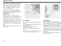
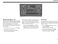
Sensors – ECC
The sun sensor is on the upper portion of the
dashboard. Remember not to cover it.
Do not cover the passenger compartment
temperature sensor on the climate control panel.
Side windows and sunroof
To ensure that the air conditioning works satisfactorily, close all side windows and the
sunroof (if fitted).
Acceleration
The air conditioning system switches off
temporarily at full acceleration. You may feel a
temporary rise in temperature.
Condensation/Drying
In warm weather, condensation from the air
conditioning system may drip under the car.
This is normal. If necessary, the fan will
start 50 minutes after the ignition switch is
turned to position 0 to dry the climate control
system for seven minutes. The fan then
switches off automatically.
Fuel economy - Electronic climate
control ECC
With ECC, the air conditioning system is
controlled automatically and is used just
enough to cool the passenger compartment and
dehumidify the incoming air. This provides
better fuel economy compared to conventional
systems where the air conditioning cools the air
to just above freezing point.
Fan function to reduce risk of battery
discharge
When the engine is switched off (even if the
ignition key is in position I or II), the fan will be
switched off automatically. To activate the fan,
turn the knob and set the desired speed. After
two minutes, the fan will reduce to a lower
speed. This is one way to avoid discharging the
battery when the engine is switched off.
Climate control
D
D
C
A
C
A
B
B
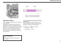
Air distribution
Air vents in the dashboard
Air vents in the door pillars
Incoming air is distributed through several
different vents located throughout the car.
A. Open
B. Closed
C. Directing airflow laterally
D. Directing airflow vertically
A. Open
B. Closed
C. Directing airflow laterally
D. Directing airflow vertically
• Aim the outer vents towards the side
windows to remove misting.
• In cold climates: close the centre vents
for the most comfortable climate and best
demisting.
• Aim the vents toward the rear side
windows to remove misting.
• Aim the vents inwards in the car for a
comfortable climate in the rear seat.
Bear in mind that small children can be
sensitive to airflow and draughts.
55
Climate control
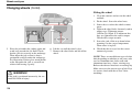
Manual climate control with air conditioning, AC
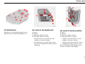
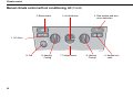
2. Recirculation
3. Air distribution
4. Rear window and door
mirror defrosters
1. AC off/on
9. Fan
8. Heating/
Cooling
• You must turn the fan knob (9) from the 0
position to connect the air conditioning.
• Use the air conditioning at low temperatures (0 - 15°C) to dehumidify incoming
air.
56
7. Twilight sensor
6. Heating/
Cooling
5. Heated front
seats
Climate control
1. AC - ON/OFF
To switch off the timer function:
The air conditioning is connected to the cooling
and dehumidification function with the ON
LED lights. The air conditioning is disconnected with the OFF LED lights.
• Press
again for more than 3
seconds. The LED lights for 5 seconds to
confirm your selection.
Recirculation is always disconnected when you
select
Defroster.
When you select Defroster
, the air conditioning is connected as long as the fan is not set
to position 0.
3. Air distribution
2. Recirculation
Recirculation can be used to shut out bad air,
exhaust, etc. from the passenger compartment.
The air in the passenger compartment is then
recirculated, i.e. no air from outside the car is
taken into the car when this function is
activated. Recirculation (together with the air
conditioning system) cools the passenger
compartment more quickly in a warm climate.
If you allow the air in the car to recirculate,
there is a risk of icing and misting, especially in
winter. The timer function minimises the risk of
ice, misting and bad air.
Activate the function as follows:
• Press
for more than 3 seconds. The
LED flashes for 5 seconds. The air recirculates in the car for 3-12 minutes
depending on the outside temperature.
• The timer function is activated each time
you press
.
Use the air distribution control positions
(marked with dots) between the different
symbols to fine-tune air distribution for
maximum comfort.
Air distribution
Air through
front and rear air
vents.
Use
When you want
good cooling in a
warm climate.
Air to windows.
Air is not recirculated in this
position. Air conditioning
is always connected.
There is a certain amount
of airflow to the air vents.
When you want to
remove ice and
misting. High fan
speed is good for
this.
Air to both floor
and windows.
There is a certain
amount of airflow to the
air vents.
When you want
comfortable conditions and good
demisting in a cold
climate. Not too
low a fan speed.
Air to floor.
There is a certain
amount of airflow
to the air vents and the
defroster vents for the
windscreen and side
windows.
Air to floor and
air vents.
When you want to
warm your feet.
In sunny weather
with cool outside
temperatures.
57
Climate control
Manual climate control with air conditioning, AC (Contd)
2. Recirculation
3. Air distribution
4. Rear window and door
mirror defrosters
1. AC off/on
9. Fan
58
8. Heating/
Cooling
7. Twilight sensor
6. Heating/
Cooling
5. Heated front
seats
Climate control
4. Rear window and door mirror
defrosters
Use this button to quickly remove misting and
ice from the rear window and door mirrors, see
page 42 for more information about this
function.
5. Heated front seats
Do as follows for heated front seat(s):
• Press once: High heat – both LEDs in the
switch light up.
• Press once again: Low heat – one LED in
the switch lights up.
• Press yet again: Heating is switched off –
no LEDs in the switch are lit.
Your Volvo workshop can adjust the temperature.
6. and 8. Heating/Cooling –
left/right side
Turn to set how warm or cold the incoming air
should be. For cooler air, the air conditioning
must be connected.
7. Twilight sensor
Automatically adjusts the brightness of
instrument illumination.
9. Fan
Fan speed can be increased or decreased by
turning the knob.
59
Climate control
Electronic Climate Control (ECC)
2. Recirculation/Multifilter with sensor
3. Recirculation
4. AUTO
5. Air distribution
6. Passenger compartment
temperature sensor
7. Defroster,
windscreen and
side windows
8. Rear window and
door mirror
defrosters
1. AC on/off
13. Fan
9. Heated front
seats
12. Temperature, lefthand side
11. Twilight sensor
10. Temperature,
right-hand side
14. Fan, rear
passenger
compartment
(option in
cars seating
seven)
60
Climate control
1. AC – ON/OFF
The air conditioning system is controlled
automatically by the system when the ON LED
is lit. This way, incoming air is cooled and
dehumidified sufficiently. When AC OFF is
selected and the OFF LED lights, the air conditioning system is disconnected; other functions
are still controlled automatically. The air conditioning system operates down to approximately
0°C.
When you select Defroster, the air conditioning
system is controlled so that air is maximally
dehumidified.
2. Air quality sensor with multifilter (option in certain markets)
Certain cars are equipped with a "Multifilter"
and air quality sensor. The Multifilter separates
gases and particles, thus reducing the volume of
odours and pollutants entering the car. The air
quality sensor detects increased levels of
contaminants in the outside air. When the air
quality sensor detects contaminated outside air,
the air intake is closed and the air in the
compartment is recirculated. The Multifilter
also cleans the air recirculating in the
compartment.
Operation
Press
to activate the air
quality sensor (normal setting).
Or:
Select one of the following three functions by
pressing
repeatedly.
• AUT LED lit: The air quality sensor is
now activated.
• No LED lit: Recirculation is not activated
unless needed to cool in a warm climate.
• MAN LED lit: Recirculation is now
activated.
Keep in mind the following:
• Make it a rule to have the air quality
sensor activated at all times.
• Recirculation is limited in cold climates
to avoid misting.
• If misting occurs, you should deactivate
the air quality sensor.
• If misting occurs, you can use the
defroster functions for the windscreen,
side windows and rear window. See
page 63.
• Follow the Volvo Service Programme for
the recommended replacement interval of
the Multifilter. If the car is used in a
severely contaminated environment, it
may be necessary to change the Multifilter more often.
When the air quality sensor is active, the green
AUT LED lights in
.
61
Climate control
Electronic Climate Control (ECC) (Contd)
2. Recirculation/ 3. Recirculation
Multifilter with
sensor
4. AUTO
5. Air distribution
6. Passenger
compartment
temperature sensor
7. Defroster,
windscreen
and side
windows
14. Fan, rear
passenger
compartment
(option in
cars seating
seven)
8. Rear window and
door mirror
defrosters
1. AC on/off
9. Heated front
seats
13. Fan
12. Temperature,
left-hand side
11. Twilight sensor 10. Temperature,
right-hand side
3. Recirculation
Activate the function as follows:
Recirculation can be used to shut out bad air,
exhaust, etc. from the passenger compartment.
The air in the passenger compartment is then
recirculated, i.e. no air from outside the car is
taken into the car when this function is
activated.
• Press
for more than 3 seconds. The
LED flashes for 5 seconds. The air recirculates in the car for 3-12 minutes
depending on the outside temperature.
• The timer function is activated each time
you press
.
To switch off the timer function:
If you allow the air in the car to recirculate,
there is a risk of icing and misting, especially in
winter.
The WLPHUIXQFWLRQ (cars with Multifilter and
air quality sensor have no timer function)
minimises the risk for ice, misting and bad air.
62
• Press
again for more than 3
seconds. The LED lights for 5 seconds to
confirm your selection.
Recirculation is always disconnected when you
select
Defroster.
4. AUTO
The AUTO function automatically regulates
climate control so that the desired temperature
is attained. The automatic function controls
heating, air conditioning, fan speed,
recirculation, and air distribution. If you select
one or more functions manually, the other
functions continue operating automatically. All
manual settings are switched off when AUTO is
switched on.
Climate control
5. Air distribution
• When the top button is depressed, air is
directed to the windows.
• When the centre button is depressed, air
is directed to the head and body.
• When the lower button is depressed, air is
directed to the legs and feet.
8. Rear window and door mirror
defrosters
Use this button to quickly remove misting and
ice from the rear window and door mirrors, see
page 42 for more information about this
function.
9. Heated front seats
Press AUTO to return to automatic air distribution.
6. Passenger compartment
temperature sensor
The passenger compartment temperature sensor
monitors the temperature inside the car.
7. Defroster – windscreen and
side windows
Use this button to quickly remove misting and
ice from the windscreen and side windows. The
air flows to the windows at high fan speed. The
LED in the defroster button lights when this
function is activated. The air conditioning
system is now controlled so that the air is
maximally dehumidified. The air is not recirculated.
13. Fan
Fan speed can be increased or decreased by
turning the knob. If AUTO is selected, fan
speed is controlled automatically. The previously set fan speed is disconnected.
If the knob for the fan is turned so far to the left
that only the left LED above the knob lights
with an orange glow, the fan and air conditioning are switched off.
Do as follows for heated front seat(s):
• Press once: High heat – both LEDs in the
switch light up.
• Press once again: Low heat – one LED in
the switch lights up.
• Press yet again: Heating is switched off no LEDs in the switch are lit.
Your Volvo workshop can adjust the temperature.
14. Fan, rear passenger
compartment
Fan speed can be increased or decreased by
turning the knob. This only applies if AC is
selected in both the front (1) and rear; see
page 37.
10 and 12. Temperature
The two knobs can be used to set the temperature for the passenger and driver’s sides of the
car. Remember that the car does not heat up or
cool down any more quickly even if you select
a higher or lower temperature than you want in
the passenger compartment.
11. Twilight sensor
Automatically adjusts the brightness of
instrument illumination.
63
Climate control
Parking heater (option)
The parking heater can be started immediately
or set to two different start times using TIMER
1 and TIMER 2.
Here, start time refers to the time point the car
should be completely warmed up.
Vehicle electronics calculates start time based
on current outside temperature. If the outside
temperature exceeds 25°C, heating is not
switched on.
At temperatures of -7°C and below, the parking
heater runs a maximum of 60 minutes.
If repeated attempts to start the parking heater
are unsuccessful, an error message is shown in
the display - contact a Volvo workshop.
64
Brief press of RESET (C)
setting of hours and minutes
Long press of RESET
timer activated (ON)
Long press of RESET
timer switched off (OFF)
ON lamp lights
the timer is activated
ON lamp flashes
the parking heater is activated
The car must be outdoors
Direct start of heater
Remember that the car must be outdoors when
using petrol and diesel heaters.
• Use the thumb wheel (B) to select
DIRECT START.
• Press the RESET button (C) to make ON
and OFF selections available.
Select ON. The heater will now run for 60
minutes. Heating of the passenger compartment
will begin as soon as the engine coolant has
reached a temperature of 20°C.
Parking on a hill
If you park your car on a steep incline, the front
of the car should be facing up the slope to
ensure the supply of fuel to the parking heater.
Deactivation of heater after direct start
• Use the thumb wheel (B) to select
DIRECT START.
• Press the RESET button (C) to make ON
and OFF selections available.
• Select OFF.
Climate control
Setting TIMER 1 or 2
Deactivation of timer-started heater
Battery and fuel
For reasons of safety, you can only programme
times for the following 24 hours, not several
days in a row.
Do as follows to manually switch off the heater
before the set time has elapsed:
If the battery is not sufficiently charged or the
petrol tank is close to empty, the parking heater
will be switched off.
1. Use the thumb wheel (B) to select
TIMER 1.
2. Briefly press the RESET button (C) so that
the hours setting starts to flash.
3. Use the thumb wheel to set the desired
number of hours.
4. Give the RESET button (C) a short press to
come to the flashing minutes setting.
5. Use the thumb wheel to set the desired
number of minutes.
6. Give the RESET button (C) a short press to
confirm your setting.
7. Press the RESET button (C) to activate the
timer.
Once you have set TIMER 1 you can toggle to
TIMER 2. Make settings the same way as for
TIMER 1.
1. Press the READ button (A)
2. Use the thumb wheel (B) to scroll to the
text PARK HEAT TIMER 1 or 2. The text
ON flashes.
3. Press the RESET button (C). The text OFF
is displayed with a steady glow and the
heater is switched off.
Messages in the display
Once TIMER 1, TIMER 2 and Immediate start
are activated, the amber symbol in the
combined instrument panel lights and explanatory text is shown in the display.
When you leave the car, you will receive a
message regarding the current settings of the
system.
If this is the case, you will receive a message in
the display. Confirm the message using the
READ button (A).
Important!
Repeated use of the parking heater in combination with short trips can lead to battery
discharge and thereby difficulty starting.
If the heater is used regularly, the car should
be driven for the same amount of time as the
heater was used in order to ensure that the
generator is able to produce enough energy
to compensate for the amount consumed.
Car clock/timer
For reasons of safety, all timer settings will be
deactivated if the car clock is reset after timer
settings have been made.
65
Climate control
66
Interior
Front seats
68
Rear seats
72
Interior lighting
74
Storage compartments in the passenger
compartment
76
Cargo compartmen
80
cargo compartment
85
Warning triangle (certain countries)
86
67
Interior
Front seats
Height adjustment – front seat
The front edges of the driver’s and passenger
seats can be adjusted to seven different settings
and the rear edges to nine different settings.
Front control (A): Adjusting the front edge of
the seat.
Rear control (B): Adjusting the rear edge of the
seat.
Front-rear adjustment
Lumbar
support
The seat can be moved front or back when the
bracket is lifted.
Backrest rake
Check that the seat has locked into position
after adjusting.
Clockwise: back
Anticlockwise: forward
WARNING!
Adjust the seat before you begin driving.
Front-rear
adjustment
Control panel
68
Interior
Lowering the front seat backrest
The front passenger seat backrest can be folded
to a horizontal position to make room for a long
load. Fold the backrest as follows:
• Move the seat as far back as possible.
• Adjust the backrest to the upright
position.
• Lift the catches on the rear of the
backrest.
• Fold the backrest forward.
69
Interior
Power seat (option)
Preparations
Passenger seat: The seat can only be
adjusted if the ignition key is in position I or II.
'ULYHU¶VVHDW The seat can be adjusted if the
ignition key is in position I or II. It can also be
adjusted in the following circumstances:
1. Within 40 seconds of the ignition key being
turned to position 0 or removed from the
ignition switch.
2. After you have unlocked the driver’s door
with the key or remote control, the driver’s
seat can be adjusted during a 10 minute
period LIWKHGRRUUHPDLQVRSHQ If the
door is closed, the seat can be adjusted for
40 seconds.
The ignition key can be in position or not
yet inserted in the ignition switch.
Memory function in the remote control
(option)
When you change the position of the driver’s
seat, the new setting is saved in the remote
control when you lock the car door. The next
time you unlock the car using that remote
control and open the driver’s door within two
minutes, the driver’s seat will assume its stored
position. This only applies to the two remote
controls that are delivered with the car, page 88.
70
Seat adjustment
If your Volvo is equipped with power seats, the
following may be adjusted with the two
switches at the side of the seat:
A. Height of seat front edge
B. Front - rear
C. Height of seat rear edge
D. Backrest rake
127(The power seats have an overload
protector that activates if a seat is blocked by
any object. If this occurs, switch off the ignition
(key in position 0) and wait about 20 seconds
before using the seat again.
Seats with memory function (option)
Three positions can be stored. After adjusting
the seat and the door mirrors, hold the MEM
button depressed while pressing button 1.
Further seat and door mirror settings can be
stored in the memory using buttons 2 and 3.
6HWWLQJSUHVHWSRVLWLRQV
Hold memory button 1, 2 or 3 pressed until the
seat stops.
)RUUHDVRQVRIVDIHW\WKHVHDWZLOOVWRS
PRYLQJLIRQHRIWKHVHWWLQJEXWWRQVLV
UHOHDVHG
Interior
Emergency stop
If the seat accidentally begins to move, press
one of the buttons to stop the seat.
WARNING!
When adjusting, ensure that there are no
objects in front of or behind the seat. Ensure
that none of the rear seat passengers will be
pinched. To avoid this possibility, ensure
that children do not play with the switches.
71
Interior
Rear seats
1
2
Rear seats – second row (cars
seating seven)
Lowering the backrest for entry into the
car
• Lift/pull the handle (1) up while pushing
the backrest forward. Do the reverse to
return the seat to its original position.
Adjusting the seat front - rear
• Lift the bracket (2) to move the seat front
or back.
72
A
Sliding seat (cars seating seven)
Removing the centre console
The centre seat in the second row can be slid
farther forward than the other seats. Sliding the
seat completely forward improves contact
between a child sitting on the integrated booster
cushion and front seat occupants.
The centre console must first be removed if you
wish to slide the centre seat in the second row
forward.
Lift the bracket (A) to move the seat front or
back.
• Remove the centre console by pulling the
catch straight out as illustrated above.
• Then lift the console out of the way.
Interior
WARNING!
The lowest position should only be used
when the backrest is to be folded down or
when no one is sitting in this seat.
After raising the backrests in the second and
third row of seats, it is important to make
sure that the backrests have locked into
place. Otherwise the protective system of
the seats may be compromised.
Rear seat head restraint – centre
seat
The centre seat head restraint can be adjusted to
four different heights. Slide the head restraint
up as desired. Press in the release button to
lower it. See illustration!
Note that the head restraint cannot be removed
completely!
73
Interior
Interior lighting
General lighting lights up and remains lit for
10 minutes when...
• one of the doors is open.
• unless general lighting is switched off.
General lighting goes out when...
• the engine is started.
• you lock the car from outside using the
key or remote control.
General lighting can be switched on or off in all
situations by briefly pressing the button.
General lighting
General lighting can be switched on and off in
all situations by briefly pressing the centre
button. General lighting has a built-in automatic
function, which means that it lights up and
remains lit for 30 seconds or 10 minutes if the
engine is switched off.
General lighting lights up and remains lit for
30 seconds when you...
• unlock the car from the outside using the
key or remote control.
• stop the engine and turn the ignition key
to position 0.
74
Unless switched off manually, general lighting
goes out automatically
10 minutes after the engine is switched off.
You can switch off the timer by pressing the
button for more than 3 seconds. When you then
briefly press the button again, the timer reconnects.
The pre-programmed times of 30 seconds and
10 minutes can be changed. Contact an
authorised Volvo workshop.
Reading lamps
Reading lamps can be switched on or off by
pressing the respective button. For cars seating
seven, both reading lamps for the third row of
seats are switched on or off when one of the
buttons is pressed. Unless switched off
manually, reading lamps are switched off
automatically 10 minutes after the ignition is
switched off.
Interior
Floor mats
Volvo offers floor mats specially manufactured
for your car. They must be properly placed and
secured in the mat clips so that they do not get
caught in or under the pedals at the driver’s seat.
Vanity mirror
The lamp comes on when you open the cover.
75
Interior
Storage compartments in the passenger compartment
6WRUDJHFRPSDUWPHQWLQ
WKLUGURZRIVHDWV
6WRUDJHFRPSDUWPHQWDQGFXSKROGHU
7LFNHWFOLS
*ORYHER[
6WRUDJHWUD\LQ
FHQWUHFRQVROH
*URFHU\EDJKROGHU
6WRUDJHSRFNHW
&XSKROGHUIRUUHDUVHDWSDVVHQJHUVRSWLRQ
WARNING!
Make sure that no hard, sharp or heavy objects lie or protrude in such a way that they could cause injuries during heavy braking.
Always secure large, heavy loads with one of the seat belts.
76
Interior
Pen holder
Glovebox
Coat hanger
The dashboard contains a compartment for
pens.
The glovebox can be used to store things such
as the Owner’s Manual, maps, pens and petrol
cards.
Use the coat hanger for clothes of normal
weight.
77
Interior
Storage compartments in the passenger compartment (Contd)
Ashtray for rear seat passengers
(option)
Cup/bottle holder for
rear seat passengers (option)
Storage compartment and cup
holder (cars seating seven)
Open the ashtray by pulling the top edge
outwards.
Pull the bottom edge of the insert to open. The
cup holder insert can be removed: Detach the
two clips so the holder can be used for large
bottles.
This storage compartment can be used for CDs,
books and the like.
To empty:
• Open the ashtray.
• Press the cover outwards and tip it back.
• Then lift it out.
78
Interior
Centre console centre console
Cup holder
The centre console contains a storage tray for
food and drinks, for example. The armrest can
be folded back to make a "table" for rear seat
passengers.
Cup holder for front seat passengers.
Storage compartment in the
third row of seats (cars seating
seven)
Ashtray (option)
This storage compartment can be used for pens
and other small items.
Pull out the insert to empty the astray.
79
Interior
Cargo compartmen
1
Extending the cargo
compartment – second row of
seats
1. Set the seats in their rearmost positions
(applies only to cars seating seven).
2. Lower the head restraint.
3. Release the catch (1) and fold down the
backrest. Press down to lock the backrest in
its folded position.
WARNING!
For reasons of safety, no passengers should sit
in the third row of seats if the outer head
restraints in the second row are lowered.
80
Extending the cargo
compartment – third row of
seats (cars seating seven)
Place the rear seats in the entrance/exit
position., see page 72.
1. Pull the handle up.
2. Slide the seat cushion to its rearmost
position. Fold in the right and left-hand
cargo eyes in order to avoid damage when
lowering the backrest.
3. Fold down the backrest (The head restraint
folds in automatically when the backrest is
folded).
Repositioning the seats in the
third row
• Raise the backrest to its normal position.
• Take hold of the eyes and pull out the seat
cushion until you hear a click.
• The seat is now secured in its normal
position.
Interior
• Position wide loads on each side of the
division in the backrest.
• Secure the load with retaining straps
using the car’s lashing eyes.
• Never load above the backrest without a
load net.
WARNING!
Loading the cargo compartment
The seat belts and airbags provide the driver
and passengers substantial protection,
especially in head-on collisions. But, you must
also remember to protect yourself from injuries
from behind. When loading cargo, bear in mind
that improperly secured or incorrectly loaded
objects in the cargo compartment could be
thrown forward with great speed and force in
the event of a collision or sudden braking,
causing serious injuries.
Bear in mind that if an object weighing 20 kg is
subjected to a head-on collision at a speed of 50
km/h, its impact weight will be 1000 kg.
Think about the following when loading:
• Do not load extremely heavy objects
up by the front seats. The lowered
backrest will be pressed down unnecessarily hard.
• Never load cargo above the backrests!
If you do so, the load could be thrown
forward in the event of sudden
braking or a collision and severely
injure you or your passengers.
Remember to always secure (bind) the
load properly.
• If the rear seat backrest is lowered, do
not load the car higher than 50 mm
under the top edge of the rear
passenger windows. Leave 10 cm of
free space from the windows inwards.
Otherwise, the intended protection of
the inflatable curtain, which is hidden
in the headlining, may be compromised.
WARNING!
• Always secure the load. During heavy
braking the load may otherwise shift,
causing personal injury.
• Cover sharp edges with something
soft.
• Turn off the engine and apply the
parking brake when loading or
unloading long objects! You may
accidentally knock the gear lever or
gear selector with the load and cause a
gear to engage and the car to move
off.
• Place the load by the backrest.
• Position heavy loads as low as possible.
81
Interior
Cargo compartmen (Contd)
1
Safety net
The safety net prevents luggage and cargo from
being thrown forward in the passenger
compartment during heavy braking.
The net is made of a strong nylon fabric and can
be secured two different ways:
1. Behind the rear seat backrest
2. Behind the front seats if the rear seat is
lowered.
Fitting the safety net
1. If the car is equipped with a privacy panel,
remove it before fitting the safety net.
2. Hook the upper rod in the front or rear roof
mounting.
82
3. Hook the other end of the rod in the roof
mounting on the other side.
4. Secure the safety net anchoring straps in
the eyes on the floor if the net is secured in
the rear roof mountings.
Use the eyes in the seat slide rail if the net
is secured in the front roof mountings.
Applies only to cars seating seven:
• Make sure the net lies in front of the side
panel armrest when securing.
5. Tension the safety net using the anchoring
straps.
Folding up the safety net
The safety net can be folded up and placed in
the cargo compartment floor (for cars seating
five).
• Press the buttons (1) in the safety net
hinges to release the hinges and fold up
the net.
WARNING!
• Make sure that the upper mountings of
the safety net are correctly fitted and
that the anchoring straps are securely
fastened.
• Do not use a damaged net.
Interior
WARNING!
For cars seating seven: For reasons of safety,
no passengers should sit in the third row of
seats if the protective grille is positioned
behind the second row of seats.
Protective steel grille (option)
The protective grille in the cargo compartment
prevents cargo or pets from being thrown
forward in the passenger compartment in the
event of heavy braking.
For reasons of safety, the protective grille must
always be mounted and secured correctly.
Fit the protective grille as follows:
1. Lift in the protective grille through the
tailgate opening or one of the rear
doorways (fold down the seats in the
second row if necessary).
2. Insert one of the protective grille
mountings in its bracket above the rear
door behind the second row of seats.
3. Slide the protective grille mounting to the
front position of the bracket.
4. Place the other protective grille mounting
in its bracket above the other rear door and
slide it to the front position.
5. Insert the attaching brace through the lower
mounting in the protective grille from
underneath, as indicated in the illustration.
6. Fit the spring on the attaching brace and
screw in the knob.
7. Fit the attaching brace hook in the load
anchorage
and tighten the knob until the attaching
brace takes hold in the load anchorage.
8. Do the same on the other side.
9. Tighten both attaching braces alternately.
10. Fit protective caps on the exposed screw
threads above the knobs.
83
Interior
Cargo compartmen (Contd)
Electric socket in the cargo
compartment
Slide down the cover when you wish to use the
socket. It works regardless of whether the
ignition is on or off.
If the ignition is switched off and a load with
power consumption greater than 0.1 A is
connected to the electric socket, a warning
message is shown in the display.
The maximum current for the electric socket is
15 A.
Do not use the electric socket with the ignition
switched off as there is a risk of the battery
becoming discharged.
84
Privacy panel (option 7-seat)
Grocery bag holder
Pull out the privacy panel, pull it over the cargo
and hook it into the holes in the rear pillars of
the cargo compartment.
Open the tailgate. Hang or secure your grocery
bags using the tensioning straps or holders.
Removing the privacy panel
Press the end pieces of the privacy panel
inwards, pull up and release. When fitting, press
the end pieces of the privacy panel down into
the holders.
WARNING!
Do not place objects on the privacy panel.
They could injure passengers during braking
or evasive manoeuvres.
Interior
Cargo compartment
4
127(Do not put anything in the area the
cushions fold into. Cushions and seat mechanisms could be damaged.
3
2
3
4
2
1
1
&DUVVHDWLQJILYH
&DUVVHDWLQJVHYHQ
Compartment in cargo
compartment floor (cars seating
five)
Compartment in cargo
compartment floor (cars seating
seven)
• Lift up the hatch in the cargo
compartment floor.
If the car is equipped with a grocery bag holder:
• Lift up the floor hatch.
If the car is equipped with a grocery bag holder:
• Lift the floor hatch and loosen the
grocery bag hol der retaining straps.
The following is housed in the floor
compartment:
• Raise the upper floor hatch, loosen the
retaining straps of the grocery bag holder
and raise the lower floor hatch.
The following is housed in the floor
compartment:
1.
2.
3.
4.
1.
2.
3.
4.
Warning triangle (certain markets)
Tool kit
First-aid kit (certain markets)
Jack (alternate location)
Jack
Tool kit
Warning triangle
First-aid kit
85
Interior
Warning triangle (certain countries)
Warning triangle
Follow the warning triangle regulations of the
country you are in.
Do as follows to use the warning triangle:
• Detach the warning triangle case. It is
held in place with a velcro strap.
• Remove the warning triangle from its
case (A).
• Fold out the four support legs on the
warning triangle.
• Fold out both red sides of the warning
triangle. Place the warning triangle in a
location that is appropriate for the traffic
situation.
86
After use:
• Pack everything in reverse order.
• Make sure that the warning triangle with
case is securely fastened in the
compartment.
Locks and alarm
Keys and remote control
88
Locking and unlocking
90
Child safety locks
93
The alarm system
95
87
Locks and alarm
Keys and remote control
Keys – Immobilizer
Your car is delivered with two master keys and
one service key. One of the master keys is
foldable and equipped with an integrated
remote control.
If you lose one of your keys, take all other keys
to an authorised Volvo workshop. As a crime
prevention measure, the code of the lost key is
erased from the system. At the same time, the
other keys must be re-coded in the system.
0DVWHUNH\
This key opens all locks.
1
2
6
5
4
The mechanical key codes are recorded on a
separate label accompanying the keys. Store the
label in a safe place. Take the label to your
Volvo dealer if you wish to order new keys. A
maximum of six remote controls/keys can be
programmed and used.
8QORFN2SHQWDLOJDWH
$ODUPIXQFWLRQ$SSURDFKOLJKWLQJ
/RFN)ROGRSHQNH\
Immobilizer
Remote control functi ons
The keys are equipped with coded chips. This
code must match the reader in the ignition
switch. The car can only be started if the correct
key with the correct code is used.
1. Unlocking
3
Button 1 unlocks all doors, the tailgate and the
fuel filler flap.
2. Tailgate
Press button 2 to unlock the tailgate only.
3. Alarm function
6HUYLFHNH\
Key to front door, ignition switch and steering
wheel lock.
*: certain markets only
88
The alarm function can be used to attract
attention during emergency situations. If the red
(3) button is held for at least 3 seconds or
pressed twice in succession during the same
amount of time, the direction indicators, interior
lighting and horn will be activated. The alarm
Locks and alarm
can be deactivated with any of the remote
control buttons or it will shut off automatically
after 25 seconds.
4. Approach lighting
Do as follows when approaching your car:
• Press the yellow button (4) on the remote
control.
The interior lighting, position/parking lamps,
numberplate lighting, door mirror lamps
(option) and trailer lighting will switch on and
remain lit for 30, 60 or 90 seconds. Your
authorised Volvo workshop can select a
suitable time setting for your car.
To switch off the home safe lighting:
• Press the yellow button again.
5. Locking
Changing the remote control
battery
Lock all doors, tailgate and fuel filler flap with
button 5. There is a delay of approx. 10 minutes
for the fuel filler flap.
If the locks repeatedly fail to react to signals
from the remote control at a normal distance,
the battery should be replaced.
6. Folding/opening key
The key can be folded by pressing button 6
while folding the key blade into the keypad.
The folding key will open automatically with
one press of the button.
• Remove the cover by carefully prising up
the rear edge of with a small screwdriver.
• Change the battery (type CR 2032, 3
volt); – the plus side should face up.
Avoid touching the battery and its contact
surfaces with your fingers.
• Refit the cover. Make sure the rubber seal
is properly fitted and free from damage to
prevent water from entering.
• Turn the old battery in to your Volvo
workshop so that it is disposed of in an
environmentally friendly way.
89
Locks and alarm
Locking and unlocking
Locking and unlocking the car
from the outside
Locking and unlocking the car
from the inside
Using the master key or its remote control, all
doors and the tailgate can be un locked simultaneously – from the outside –. In this mode, the
door lock buttons and interior door handles are
inoperative.
Using the control in the door panel, you can
lock or unlock all doors and the tailgate simultaneously.
The fuel filler flap can be opened when the car
is unlocked. The flap remains unlocked for 10
minutes after the car has been locked.
90
All doors can also be locked or unlocked with
the lock buttons.
The above applies only if the car was not locked
from the outside!
Locking the glove box
The glovebox can be locked /opened with the
master key only – not with the service key.
Locks and alarm
Automatic re-locking
If none of the doors or the tailgate are opened
within two minutes of unlocking from the
outside with the remote control, all locks relock automatically. This function prevents you
from unintentionally leaving the car unlocked.
For cars with alarms, see page 95.
Locking/unlocking the tailgate
with the remote control
Do as follows to unlock the tailgate only:
• Press the button on the remote control
(see illustration) slowly twice within
3 seconds.
• If all doors are locked when you close the
tailgate, it remains unlocked and its alarm
is not armed when you close it. The other
doors remain locked with their alarms
armed.
• To arm the alarm and lock the tailgate
only when you close it, press the LOCK
button again.
127(If you use this button to unlock the
tailgate, but do QRW open it, the tailgate will relock automatically after two minutes.
91
Locks and alarm
Locking and unlocking (Contd)
Deadlocks
Your car has a special deadlock function, which
means that the doors cannot be opened from the
inside if they are locked.
Deadlocks can only be activated from the
outside by the driver’s door being locked with
the key or remote control. All doors must be
closed before deadlocks can be activated. Once
activated, the doors cannot be opened from the
inside. The car can only be unlocked from the
outside via the driver’s door or by using the
remote control.
Deadlocks are engaged after a 25 second delay
once the the doors are locked.
Temporary deactivation of
deadlocks and any detectors.
If others prefer to remain seated in the car with
the doors locked from the outside – e.g. during
transport by ferry, – it is possible to deactivate
the deadlocks.
• Insert the key in the ignition switch, turn
it to position II and then back to position I
or 0.
• Press the button (see illustration).
If the car is equipped with an alarm, movement
and tilt detectors are also deactivated. See page
96.
92
The LED in the button lights until you lock the
car with the key or remote control. A message
is shown in the display as long as the key
remains in the ignition switch. The sensors will
be reactivated the next time you switch on the
ignition.
WARNING!
Do not allow anyone to remain in the car
without first deactivating the deadlock.
Locks and alarm
Child safety locks
A
A
B
Manual child safety locks – rear
doors and tailgate
The controls for the child safety locks are in the
rear edges of the rear doors and the bottom edge
of the tailgate (certain markets). Each control is
only accessible when the door or tailgate is
open. Use the ignition key to turn the control,
thereby activating or deactivating the child
safety lock.
B
A. The door can be opened from inside.
B. The door cannot be opened from inside.
WARNING!
Remember that in the event of an accident,
rear seat passengers cannot open rear doors
from the inside if the child safety locks are
activated. 7KHUHIRUHNHHSWKHGRRUV
XQORFNHGZKLOHGULYLQJ. In the event of an
accident, rescue personnel will then be able
to quickly get into the car from the outside.
93
Locks and alarm
Child safety locks (Contd)
127(All settings in the manual child safety
system are set aside when you DFWLYDWH the
electric child safety locks.
Electric child safety locks – rear
doors (option - certain markets)
Use the button in the centre console to activate
or deactivate the child safety locks in the rear
doors. The ignition key must be in position I or
II. The LED in the button comes on when the
child safety lock is activated. A message
appears in the display when you activate or
deactivate the child safety lock.
127(The rear doors cannot be opened from
the inside as long as the HOHFWULF child safety
locks are activated.
94
Locks and alarm
The alarm system
When the alarm is connected, it continually
monitors all alarm points. The alarm is
triggered if...
•
•
•
•
•
•
•
•
the bonnet is opened
the tailgate is opened
a side door is opened
the ignition switch is turned with a nonapproved key or subjected to force
if movement is detected in the passenger
compartment
the car is raised or towed away (if fitted
with a tilt detector – option)
the battery cable is disconnected
anyone tries to disconnect the siren.
Activating the alarm
Press the LOCK button on the remote control. A
long flash from the car’s direction indicators
confirms that the alarm is armed and that all
doors are closed.
Automatic alarm activation
Alarm signals
If none of the doors or the tailgate is opened
within two minutes of the alarm being deactivated, and the car was unlocked with the remote
control, the car reactivates the alarm automatically. The car locks at the same time. This
function prevents you from accidentally leaving
the car without the alarm on.
An audible signal is given from a siren with a
reserve battery. Each alarm signal lasts 25
seconds.
Automatic alarm activation
127(Even if your remote control does not
work or you have lost it, you can start the car as
follows: open the driver’s door with the key.
The alarm is triggered and the siren sounds.
Start the car as usual. The alarm will then be
deactivated.
In certain countries (e.g. Belgium, Israel) the
alarm is activated after a certain delay if the
driver’s door was opened and closed but the car
was not re-locked.
Deactivating a triggered alarm
When the alarm is triggered, all direction
indicators flash for
5 minutes or until the alarm is deactivated as
described earlier.
Press the UNLOCK button on the remote
control if the alarm sounds and you wish to
deactivate it. Two short flashes of the direction
indicators are given as confirmation.
Deactivating the alarm
Press the UNLOCK button on the remote
control. Two short flashes from the car’s
direction indicators confirm that the alarm has
been deactivated.
95
Locks and alarm
The alarm system (Contd)
temporary deactivation ends the next time you
switch on the ignition.
If your car has deadlocks, they are reactivated at
the same time. See page 92.
Alarm LED in the dashboard
An alarm LED at the top of the dashboard (see
illustration) indicates the status of the alarm
system:
Temporary deactivation of
detectors and deadlocks
To avoid inadvertently triggering the alarm, for
example when leaving a dog in the car or during
a ferry crossing, the movement and tilt detectors
can be temporarily deactivated:
• Insert the key in the ignition switch, turn
it to position II and then back to position I
or 0.
• Press the button.
The LED in the button lights until you lock the
car with the key or remote control.
A message is shown in the display as long as the
key remains in the ignition switch. This
96
• Lamp not lit: Alarm is deactivated.
• Lamp flashes once a second: The alarm is
activated.
• Lamp flashes quickly, after deactivating
the alarm and until the ignition is
switched on: The alarm has been
triggered.
• If a fault has occurred in the alarm
system, a message is shown in the
display.
If the alarm system does not function
properly, have your car checked by an
authorised Volvo workshop.
WARNING!
Do not attempt to repair or modify alarm
system components. All such attempts may
affect terms of insurance.
Starting and driving
General
98
Refuelling
100
Starting the car
101
Manual gearbox
102
Automatic gearbox AW5 and GM with Geartronic
103
All-wheel drive
105
Brake system
106
Stability system
108
Parking assistance system (option)
110
Towing
111
Jump starting
112
Driving with a trailer
113
Towing bracket (option)
115
Load on the roof
119
97
Starting and driving
General
Economical driving
Driving on rough roads
Economical driving results from driving gently
with anticipation and adapting your driving
style and speed to the situation.
The Volvo XC90 is primarily designed for
driving on main roads, but also has good
handling properties on uneven or rough roads.
Keep the following in mind in order to preserve
the service life of your car:
Keep in mind the following:
• Drive the engine to operating temperature
as soon as possible! That is to say: do not
let the engine idle, but drive with a light
load as soon as you can.
• A cold engine consumes more fuel than a
warm one.
• Avoid driving short distances where the
engine never has time to reach operating
temperature.
• Drive gently! Avoid unnecessary quick
accelerations and heavy braking.
• Do not drive with unnecessary, heavy
loads in the car.
• Do not use winter tyres when the roads
are clear and dry.
• Remove the load carrier when it is not in
use.
• Do not open side windows unnecessarily.
Your new car – slippery road
surfaces
Driving in slippery conditions may feel
different depending on whether your car has a
manual or an automatic gearbox. Practice
driving in mock slippery conditions in order to
determine how your new car will react.
98
• Drive slowly on rough roads so you do
not damage the car’s underbody.
• If the ground is loose or is made up of dry
sand or snow, it is always best to keep the
car moving at all times and avoid shifting.
Do not stop the car.
• If the road is extremely steep and there is
a risk of overturning, never try to turn the
car around. Reverse back down. Do not
drive diagonally across an incline. Drive
in the direction of the incline.
127( Avoid driving on steep slopes with a
low fuel level. The catalytic converter may be
damaged if the engine does not receive a sufficient supply of fuel.
When driving on extremely steep inclines,
make sure that the tank is at least half full so as
not to risk engine malfunction.
Wading
The car can be driven through water with a
depth of no more than 48 cm.
127(In greater depths, water can enter the
differentials and the transmission. This reduces
the lubricating ability of the oil and shortens the
service life of the systems.
When driving through shallow water, maintain
a low speed and do not stop the car. Once you
have passed through the water, apply a light
pressure to the brake pedal and check brake
function. Water, mud and the like can dampen
brake linings, resulting in delayed braking
action.
Clean the electric contacts of the electric engine
heater and trailer coupling after driving in water
and mud.
127(Do not let the car stand with water over
the sills for any long period of time. This could
cause electrical malfunctions.
Power consumption – saving
energy
The electrical functions of the car load the
battery to varying degrees. Avoid leaving the
ignition key in position II when the engine is
switched off. Use position I instead. Less power
will then be consumed.
Examples of functions that draw a lot of current
are: fan, windscreen wipers, audio system (high
volume) and parking lamp. Be aware of
different accessories that load the electrical
system. Do not use functions that draw a lot of
current when the engine is switched off.
If the battery charge is low, a message is shown
in the display. You should charge the battery by
starting the engine.
Starting and driving
Do not allow the engine and
cooling system to overheat
Automatic gearbox
6KLIWORFN
Cold start
Under certain conditions, e.g. when driving in
hilly terrain or with a heavy load, especially in
warm weather, there is a risk of the engine and
cooling system overheating.
When starting in low temperatures, shifting
may feel harder. This is due to viscosity of the
gearbox oil at low temperatures.
The brake pedal must be depressed to move the
gear selector from position P to other gear
positions when the key is in position I or II.
To avoid the cooling system
overheating
• Drive at low speeds if driving with a
trailer up a long incline.
• Do not turn the engine off immediately
you stop, if the car has been driven hard.
• Remove any auxiliary lamps from in
front of the grille if driving in extreme
high temperatures.
To avoid the engine overheating
Do not exceed engine speeds of 4500 rpm if
driving with a trailer or caravan in hilly terrain.
The oil temperature can become too high.
Do not drive with an open
tailgate!
If you drive with the tailgate open, some of the
exhaust gases and poisonous carbon monoxide
could be sucked into the car through the cargo
compartment. If you must drive a short distance
with the tailgate open, do as follows:
• Close all windows.
• Distribute the air between the windscreen
and floor while running the fan at high
speed.
To minimise engine emissions, the gearbox
shifts up later than normal if the engine has been
started at low temperature.
,I\RXKDYHVWDUWHGWKHHQJLQHDQGWKHFDU
UHPDLQVVWDWLRQDU\
Hold your foot on the brake pedal when moving
the gear selector to another position.
When the engine is cold, the transmission shifts
gears at higher engine speeds than normal. This
is to help the catalytic converter reach normal
operating temperature quickly.
Adaptive systems
The gearbox is controlled by "adaptive
systems". The control module continually "
learns " how the gearbox behaves. It senses how
the gearbox shifts gears and achieves optimal
gear shifts each time. The control module also
senses the way you drive, such as how hard you
depress the accelerator, and adjusts the sensitivity of the shift schedule to your driving style.
Safety systems
Cars with automatic gearbox have special
safety systems:
.H\ORFN
The ignition key must be in position I to move
the gear selector from position P to other gear
positions. The gear selector must be in position
P to remove the ignition key after driving.
99
Starting and driving
Refuelling
Fuel cap
Refuelling
The fuel cap is inside the fuel filler flap on the
right rear wing.
127(Do not add cleaning additives yourself
unless specifically recommended to do so by a
Volvo workshop.
There may be overpressure in the tank if
outdoor temperatures are high. Open the cap
slowly. Do not overfill the fuel tank. Stop
refuelling when the pump cuts out for the first
time! If the tank is overfilled fuel may overflow
at high temperatures!
After refuelling, replace the fuel cap and turn
until one or more clicks is heard.
Opening the fuel filler flap
The fuel filler flap can be opened when the car
is unlocked.
127(The filler flap remains unlocked for ten
minutes after the car is locked. It then locks
automatically.
100
WARNING!
Always VZLWFKRII your mobile telephone
during refuelling – the ring signal can cause
sparks which may ignite petrol fumes and lead
to fires or personal injury.
Important!
Petrol-powered cars must always be
refuelled with unleaded petrol so as not to
damage the catalytic converter.
Filling up with diesel
At low temperatures, paraffin can precipitate
out of diesel fuel ( –5°C- –40°C). This can
cause problems when starting. Make sure you
use a special winter grade fuel during cold
periods.
Starting and driving
Starting the car
Starting the engine (petrol)
Ignition keys and immobilizer
1. Depress the parking brake.
2. $XWRPDWLFJHDUER[ Gear selector in
position P or N.
0DQXDOJHDUER[Gear lever in neutral
and the clutch pedal completely depressed.
This is especially important in severe cold.
3. Turn the ignition key to the start position.
If the engine does not start within 5-10
seconds, release the key and try again.
127(Depending on the engine temperature
at the time of the start attempt, engine speed
after a cold start may be higher than normal –
for a short time period – for certain engine
types. This is because Volvo strives to minimise
exhaust emissions by having the engine exhaust
system reach the correct operating temperature
as quickly as possible.
Do not let several ignition keys, each containing
a chip, dangle on the same keyring when
inserting the key in the ignition switch.The
immbobilizer could be activated. If this
happens, take away the excess keys and restart
the car.
Starting the engine (Diesel)
1. Depress the parking brake.
2. $XWRPDWLFJHDUER[ Gear selector in
position P or N.
0DQXDOJHDUER[Gear lever in neutral
and the clutch pedal completely depressed.
This is especially important in severe cold.
3. Turn the ignition key to the driving
position. An lamp on the combined
instrument panel will come on indicating
that the engine preheater is activated. Turn
the key to the start position when the lamp
extinguishes.
1HYHUUHYWKHHQJLQHKDUGVWUDLJKWDIWHUD
FROGVWDUW,IWKHHQJLQHGRHVQRWVWDUWRU
PLVILUHVFRQWDFW\RXUQHDUHVW9ROYR
ZRUNVKRS
Ignition switch and
steering wheel lock
0 – Locked position
The steering wheel locks
when the ignition key is
removed.
I – Intermediate position "radio position"
Certain electrical components
can be connected. The engine
electrical system is not
connected.
WARNING!
Never switch off the ignition (position 0 or
1) or remove the ignition key when the
vehicle is in motion. This could activate the
steering wheel lock, making the car impossible to steer.
Always remove the ignition key from the
ignition switch before leaving the vehicle –
especially if children remain in the car.
II – Driving position
The key position when
driving. The car’s entire
electrical system is connected.
III – Start position
The starter motor is
connected. Release the key
once the engine has started. The key automatically springs back to the driving position. If the
key is hard to turn, the front wheels may be
turned in such a way that there is tension in the
steering wheel lock. Turn the wheel back and
forth to make it easier to turn the key.
Make sure the steering wheel locks when you
leave the car. This reduces the risk of theft.
101
Starting and driving
Manual gearbox
Gear positions
Reverse gear inhibitor
Depress the clutch pedal fully with each gear
change. Remove your foot from the clutch
pedal between gear changes! Follow the appropriate shifting pattern.
Engage reverse gear when the car is stationary
or at very low speeds!
Use 6th gear as often as possible for the best
possible fuel economy.
102
Starting and driving
Automatic gearbox AW5 and GM with Geartronic
P – Park
N – Neutral
Select this position when you wish to start the
engine or park the car.
7KHFDUVKRXOGEHVWDWLRQDU\ZKHQ\RXVHOHFW
3
N is the neutral position. The engine can be
started but no gear is engaged. Apply the
parking brake when the car is stationary with
WKHJHDUVHOHFWRULQ1
In P, the gearbox is mechanically blocked.
Apply the parking brake when parking.
D – Drive
R – Reverse
7KHFDUVKRXOGEHVWDWLRQDU\ZKHQ\RXVHOHFW
5
D is the normal driving position. The car
automatically shifts between the different gears
of the gearbox based on the level of acceleration
and speed. The car should be stationary when
selecting ' from position 5.
• 5-cylinder turbo engine; 5-speed
• 6-cylinder turbo engine; 4-speed
Gear selector inhibitor
It is always possible to move the gear selector
freely forwards and backwards between 1 and
'. Other positions are locked with a catch
which can be controlled with the inhibitor
button on the gear selector. Press the inhibitor
button to move the gear selector forwards or
backwards between 5 and 1 as well as between
' , and /.
103
Starting and driving
Gear selector manual positions
To move from automatic ' to the manual
gears, press the gear selector to the left. To
move from 0$1 back to ' press the gear
selector to the right to '.
Gears 3, 4 and 5 have a lock-up function
(locked gears) which provides better engine
braking and lower fuel consumption. Only 5cylinder motors are 5-speed.
While driving
Manual gear positions can be selected at
anytime during your trip. The engaged gear is
locked until you select another gear. The car
will only shift if you slow to a very low speed.
If you move the gear selector to minus (–), the
car downshifts automatically one gear at a time
while engine braking. If you move the gear
selector to plus (+), the car upshifts one gear at
a time.
Third gear is the highest gear that can be used
when starting.
W – Winter
"Kick-down"
Use the button to switch the W programme on
and off.
Use this programme when starting and driving
on slippery surfaces.
The LED in the button is lit when the
programme is activated.
: is displayed in the combined instrument
panel.
When you press the accelerator all the way
down – beyond the position normally regarded
as full acceleration – a lower gear is automatically engaged. This is called " kick-down "
downshifting. When you reach the maximum
speed for the gear or release the accelerator
pedal from the " kick-down " position, there is
an automatic upshift. Use " kick-down " when
you want maximum acceleration, such as when
overtaking.
Note that the button is on the left-hand side of
the gear lever on right-hand drive cars.
104
The gearbox is equipped with a downshift
inhibitor on all gears.
Starting and driving
All-wheel drive
AWD – All-Wheel Drive
Snow chains
The all-wheel drive system in your Volvo is
constantly engaged and meets very high
technical requirements. Used correctly, allwheel drive provides the driver better control on
various road surfaces than conventional rearwheel drive.
Snow chains may only be fitted to the front
wheels on all-wheel drive cars.
127(To avoid damaging wheel housing
components, only use chains specially designed
and adapted for Volvo XC90.
All-wheel drive means that all four road wheels
are driven at the same time. Power is automatically distributed between front and rear wheels.
An electronically controlled clutch system
distributes the power to the pair of
wheels that grips best. This provides the best
traction and prevents wheel spin.
Under normal driving conditions, the majority
of power is transmitted to the front wheels.
The greater traction improves driving safety in
rain, snow and icy conditions.
Tyre sizes and pressures
Volvo recommends that you only drive with
tyres of the same brand, size, specifications,
load designation, and speed designation. Tyre
sizes and pressures are specified in the table on
the inside of the fuel filler flap and in the
Owner’s Manual. See page 125.
105
Starting and driving
Brake system
If a brake circuit fails
The brake pedal can be depressed
further and feels softer than usual.
It also requires more pressure on
the pedal to achieve a normal braking effect.
If the brakes are heavily loaded
The brake servo only works when the
engine is running.
When driving in the Alps or other roads with
similar characteristics, the car’s brakes are
heavily loaded even if you are not pressing the
pedal especially hard. Because speed is often
low, the brakes are not cooled as effectively as
when driving on flat roads.
If the car is rolling or being towed with the
engine switched off, you must apply approximately 5 times more pressure on the brake pedal
than when the engine is running. 7KHEUDNH
SHGDOIHHOVULJLGDQGKDUG
In order to prevent abnormal brake stress, shift
down and use the same gear uphill and downhill
instead of using the brake (manual gearbox).
Thus, engine braking works more efficiently
and brake use will be necessary during short
periods only.
127(When braking with a switched off
engine, depress the brake pedal one time hard
and distinct – not repeatedly.
Moisture on the brake discs and brake
lining alter braking characteristics!
Brake components become wet when the car is
driven in heavy rain or through pools of water
or when the car is washed. This alters brake pad
friction characteristics so that there is a delay
before braking effect is noticed. Depress the
brake pedal lightly from time to time when
driving long distances in rain or slush and
before parking your car in such conditions. This
helps the brake lining warm up and dry out. You
should also do this when driving after washing
the car and when starting in damp or cold
weather conditions.
106
Keep in mind that the brakes are even more
heavily loaded when driving with a trailer.
Starting and driving
Antilock braking
system (ABS)
The ABS system (Anti-lock
Brake System) is designed so
that the wheels do not lock when braking. This
retains the best possible steering response when
braking. This
improves your ability to swerve to avoid
obstacles. The ABS system does not increase
your total braking capacity. However, as the
driver you have increased ability to steer and
thus better control over the car, which in turn
increases safety.
After the engine has started and reached a speed
of about 20 km/h, a short self-test can be both
heard and felt. When the ABS system functions,
you can hear and feel pulses in the brake pedal.
This is completely normal.
Electronic Brakeforce
Distribution (EBD)
The Electronic Brakeforce Distribution system
(EBD) is an integrated part of the ABS system.
The EBD system controls the brake force to the
rear wheels so that the best possible braking
force is always available. Pulses will be heard
and felt through the brake pedal when the
system regulates brake force.
If the %5$.(
and $%6
warning
symbols light at the same time, there is a risk
that the rear end will have a tendency to slide
during heavy braking. If the brake fluid level
is normal, carefully drive the car to the
nearest authorised Volvo workshop to have
the brake system checked.
127(You must depress the brake pedal fully
to take maximum advantage of the ABS system.
Do not release the pedal when you hear and feel
the ABS pulses. Practice braking with the ABS
system in a untrafficked area.
7KH$%6V\PEROOLJKWVDQGVKLQHVZLWKD
FRQVWDQWJORZ
• for approximately two seconds when you
start the car to test the system.
• if the ABS system has shut down due to a
fault.
107
Starting and driving
Stability system
DSTC – Dynamic
Stability and Traction
Control
The Dynamic Stability and Traction Control
system (DSTC) comprises several different
functions:
• 7UDFWLRQ&RQWURO7&
The Traction Control function transfers
power from the spinning drive wheel to
the drive wheel which has grip by braking
the spinning drive wheel. To increase
forward traction in this situation, you may
need to depress the accelerator more than
usual. A pulsing sound is heard when
Traction Control is working. This is
completely normal. The TC function is
most active at low speeds. It cannot be
switched off.
• 6WDELOLW\&RQWURO6&
The Stability Control function is designed
to prevent the drive wheels from slipping
during acceleration by lowering
engine torque. This improves navigation
and road safety on slippery surfaces.
Under certain conditions, such as when
driving with snow chains or in deep snow
or sand, it may be beneficial to switch off
108
the SC function to increase traction. This
is done using the DSTC button.
• $FWLYH<DZ&RQWURO$<&
The Active Yaw Control function
automatically brakes one or more of the
wheels to stabilise the car in the event of
a skid. If you were to depress the brake
pedal in this situation, it would feel more
rigid than usual and a pulsing sound
would be heard. For reasons of safety, the
AYC function is always active and
cannot be switched off.
• 5ROO6WDELOLW\&RQWURO56&
The Roll Stability Control function
automatically brakes one or more wheels.
This stabilises the car laterally so as to
minimise the risk of overturning due to a
skid or the like. If you were to depress the
brake pedal in this situation, it would feel
more rigid and a pulsing sound would be
heard. For reasons of safety, the RSC
function is always active and cannot be
switched off.
DSTC button
The DSTC button in the centre console is used
to reduce or reactivate the DSTC system.
Reducing the system means that the Stability
Control (SC) and Active Yaw Control (AYC)
functions are reduced. Other functions are not
affected.
When the LED in the button is lit, the DSTC
system is activated (assuming there is no fault).
127(For reasons of safety, the button must
be depressed for at least one half second to
reduce the DSTC system function.
127(The LED in the button is extinguished
and "DSTC SPIN CONTROL OFF" is shown in
the display.
The DSTC system is automatically reactivated
each time the engine is started.
The warning symbol
flashes when...
• The SC function works to keep the car’s
drive wheels from slipping.
• The TC function works to improve the
car’s traction.
• The AYC function works to keep the car
from skidding.
• The RSC function works to prevent the
car from overturning.
Starting and driving
The warning symbol
lights and
goes out again after 2 seconds when...
Emergency Brake Assistance
(EBA)
• the car is started. (The lamp lights for a
system check.)
The LED in the button goes out and the
text "DSTC SPIN CONTROL OFF" is
shown in the display when...
The (EBA) function is integrated in the DSTC
system and is designed to provide immediate
maximum braking force whenever rapid brake
application is necessary. The system detects the
need for heavier braking by registering how
quickly the brake pedal is applied.
• The SC function of the DSTC system has
been reduced with the DSTC button.
The EBA function is active at all speeds. For
reasons of safety, it cannot be switched off.
The warning symbol
shines with a
steady amber glow and the text
"TRACTION CONTROL TEMPORARILY
OFF" is shown in the display when...
127(When the EBA function is activated,
the brake pedal sinks while maximum braking
force is applied. Continue braking without
releasing the brake pedal. The EBA function
disengages when the pressure on the brake
pedal is released.
• the TC function of the brake system has
been temporarily reduced due to high
brake temperature. The TC function is
reactivated automatically when the brake
temperature returns to normal levels.
The warning symbol
shines with a
steady amber glow and the text "ANTISKID SERVICE REQUIRED" is shown in
the display when...
WARNING!
Under normal driving conditions, the DSTC
system improves the car’s road safety, but
this should not be taken as a reason to
increase speed. Always follow the usual
precautions for safe cornering and driving
on slippery surfaces.
• The DSTC system has shut down due to a
fault.
109
Starting and driving
Parking assistance system (option)
Function of the parking
assistance system
Activating/deactivating the
parking assistance system
The parking assistance system is used as a
parking aid. A tone from the audio system
speaker indicates the distance to the detected
object. The volume of any other sound from the
audio system is muted. The closer you come to
the object, the more frequent the tone. At a
distance of about
30 cm, the tone is constant. Distance is
measured using ultrasound technology via
sensors in the bumper. The measurement area
straight behind the car is about 1.5 m.
Unless deactivated with the button in the switch
panel, the parking assistance system is activated
when reverse gear is engaged. The LED in the
button lights when the system is active.
127(Switch off the system when driving
with a trailer or a bicycle rack on the towing
bracket. Otherwise, the sensors will react.
110
Fault indication
If a fault should arise in the system, the LED in
the button will go out. A text message will be
shown in the combined instrument panel
display.
Cleaning the sensors
The sensors must be cleaned regularly to ensure
that they work properly. Clean them with water
and car shampoo.
WARNING!
The parking assistance system is a parking
aid, but can never replace the driver’s
responsibility when parking. The sensors
have blind spots where objects may not be
detected. Be aware of children or animals in
the vicinity of the car.
Starting and driving
Towing
Do not tow start (bump start) the
engine
If you bump start a car with manual gearbox,
the catalytic converter(s) may be damaged.
Cars with an automatic gearbox cannot be bump
started. Use a booster battery if the battery is
flat.
If the car must be towed
• Unlock the steering wheel lock so that the
car can be steered.
.HHSLQPLQGWKHKLJKHVWOHJDOO\
SHUPLVVLEOHVSHHG
• Remember that the brake and power
steering servos do not function with the
engine switched off! You must exert
approximately five times more pressure
on the brake pedal and steering is considerably heavier than usual.
• Drive gently. Keep the towline taut to
avoid unnecessary jerking.
)RUDXWRPDWLFJHDUER[HV
• The gear selector should be in position N.
• Highest permissible speed for cars with
automatic gearbox (with the car raised):
80 km/h. Longest permissible distance:
80 km.
• Only tow with the car facing forward.
• The engine cannot be towed to start
(bump started). See "Jump starting" on
the next page.
7RZLQJH\H
IURQW
7RZLQJH\HUHDU
Towing eye
The towing eye is in the tool kit in the cargo
compartment. You must screw the towing eye
into place before towing. The socket and cover
for the towing eye are on the right-hand side of
each bumper.
127(Us the towing eye for towing on roads
only, not for recovery after driving into a ditch
or the like. Consult a professional whenever
towing is necessary.
Remove the cover as follows:
A. Loosen the bottom edge of the cover with a
coin.
B. Screw the towing eye securely into place up
to the flange (C). You can use a wheelbrace.
After use, unscrew the towing eye and refit the
cover.
111
Starting and driving
Jump starting
4
2
3
If for some reason the battery in your car is
discharged, you can " borrow " current from a
spare battery or another car’s battery to start the
engine. Always check that the clamps are
secure so that there are no sparks during the
start attempt.
To avoid the risk of explosion, we recommend
you do exactly as follows.
• Turn the ignition key to position 0.
• Ensure that the booster battery has YROWFXUUHQW
112
WARNING!
1
Jump start with a booster
battery as follows...
• Start the engine of the "booster car". Let
the engine run a few minutes at a speed
slightly higher than idle, 1500 rpm.
• Start the engine of the car with the
discharged battery.
• Remove the clamps in reverse order.
127(Do not remove the clamps during the
start attempt; risk of spark build-up.
• If the booster battery is in another car,
stop the engine of that car and make sure
the cars are not touching.
• Connect the red cable to the positive
terminal (1+) of the booster battery and
the red connection in your car’s engine
compartment (2+).
Connect the clamp to the contact point
under a small black cover which has a
plus sign on it. The cover is integrated
with the fuse box cover.
• Connect one clamp of the black cable to
the negative terminal of the booster
battery (3–).
• Connect the other clamp of the black
cable to the lifting eye on your car’s
engine (4–).
Remember that batteries, especially the
booster battery, contain oxyhydrogen which
is highly explosive. A spark, which can be
caused if you incorrectly fit the jump leads,
is enough to cause the battery to explode and
both damage the car and injure you. The
battery also contains sulphuric acid, which
can cause serious corrosive damage.
If the acid comes into contact with your
eyes, skin or clothes, flush with large
quantities of water. If acid splashes into your
eyes contact a doctor immediately.
Starting and driving
Driving with a trailer
• The car’s towing bracket must be of an
approved type.
• If the towing bracket is fitted by Volvo,
the car is delivered with the necessary
equipment to drive with a trailer. If retrofitting, check with your Volvo dealer to
ensure that the car is fully equipped to
drive with a trailer.
• Distribute the load in the trailer so that
the weight on the towing bracket is
approximately 50 kg for trailer weights
under 1200 kg and approximately 90 kg
for trailer weights over 1200 kg.
127(The weight on the towing
bracket (50/90 kg) is part of the vehicle's
load capacity.
The load in the cargo compartment may
need to be reduced so that axle load and/
or total weight do not exceed the
maximum limits when driving with a
trailer.
• Increase tyre pressure to correspond to
the pressure for full load. See the tyre
pressure table!
• Clean the towing bracket regularly and
grease the towball* and all moving parts
to prevent unnecessary wear.
• Do not drive with a heavy trailer when
your car is brand new! Wait until it has
gone at least 1000 km.
• The brakes are loaded much more than
usual on long and steep downhill slopes.
Downshift to a lower gear and adjust your
speed.
• If the car is driven with a heavy load in a
hot climate, the engine and gearbox may
overheat. The temperature gauge in the
combined instrument panel goes into the
red zone when the car overheats. Stop and
let the engine idle a few minutes.
• If the car overheats, the air conditioning
system can be temporarily switched off.
• The gearbox reacts with a built-in
protection function if the car overheats.
See the message in the display!
• The engine is loaded more heavily than
usual when driving with a trailer.
• For reasons of safety, you should not
drive faster than 80 km/h, even if the laws
of certain countries permit higher speeds.
• The maximum permissible trailer weight
for a trailer without brakes is 750 kg.
• Select position P (automatic gear box) or
engage a gear (manual gearbox) when
parking with a trailer and always apply
the parking brake. If you are parking on a
steep incline, place chocks behind the
wheels.
* Does not apply to ball hitch with vibration
damper.
0D[LPXPSHUPLVVLEOH
WUDLOHUZHLJKWIRUDWUDLOHU
ZLWKEUDNHV
%DOO
SUHVVXUH
0-1200 kg
50 kg
2250 kg
90 kg
127(The above are the highest trailer
weights permitted by Volvo Car Corporation.
Remember that national traffic regulations may
further limit trailer weight and speed. Towbars
may be certified for higher tow weights than the
car may tow.
WARNING!
If you do not follow the given recommendations, the trailer and car may be difficult to
control during evasive manoeuvres and
braking. This could be dangerous to you and
others on the road.
113
Starting and driving
Driving with trailer and
automatic gearbox
• When parking on hills, you should apply
the parking brake before moving the gear
selector to P. When you start on a hill,
you should first put the gear selector in
drive and then release the parking brake.
• Select a low gear in the gearbox when
driving on steep inclines or when driving
slowly. This prevents the gearbox from
upshifting. The gearbox oil will be
cooler.
• Do not use a higher manual gear than the
engine can "handle". It is not always
economical to drive in high gears.
• Avoid driving with trailer and automatic
gearbox on inclines exceeding 15%.
127(Some models require an oil cooler for
the automatic gearbox when driving with a
trailer.
Check with your nearest Volvo dealer as to
what applies to your car if you have a retrofitted
towbar.
114
Levelling (option on cars seating
five, standard on cars seating
seven)
If your car is equipped with automatic
levelling, the rear suspension always retains the
correct ride height regardless of the load. When
the car is stationary, the rear suspension sinks,
which is completely normal.
Starting and driving
Towing bracket (option)
127(Check that the car is equipped with
transmission oil cooling if the towing bracket is
retrofitted.
Fixed towbar (A)
Always remember to fasten the trailer’s safety
cable to the attachment. See the illustration!
A
Detachable towbar (B)
Always follow mounting instructions carefully.
Always remember to fasten the trailer’s safety
cable to the attachment. See the illustration!
$OZD\VUHPHPEHUWRFOHDQDQGJUHDVHWKH
FRQQHFWRUSLQUHJXODUO\
8VHUHFRPPHQGHGJUHDVH
B
If your car is
equipped
with a Volvo
detachable
towbar:
• Make sure that the towbar is locked
before you begin driving.
• The red signal pin (see the arrow in
the illustration above) should not be
visible.
• Use the key to lock it. See the
description on page 117.
127(Your car may have a towing bracket
with a 13 pin contact that you must connect to a
trailer with a 7 pin contact. In such a case, use a
Volvo Genuine adapter cable. Make sure that
the cable does not drag on the ground.
115
Starting and driving
$WWDFKPHQWSRLQWVXQGHUWKHFDU
Specifications
Distance A above:
Distance B above:
Fixed towbar:
1124 mm
Fixed towbar:
80 mm
Detachable towbar:
1124 mm
Detachable towbar:
80 mm
Max. permissible ball pressure: 90 kg
116
Starting and driving
Detachable towbar – mounting
1
2
OPEN
3
OPEN
B
Remove the connector pin cover.
4
Put in the key and turn it clockwise to the Hold the towball section and turn the
unlocked position.
handle clockwise until it stops.
5
PUSH TO
LOCK
6
LOCKED
RED PIN (B) NOT
VISIBLE
Push the towball section in until it locks. Check that the signal pin (B) is pushed
Be careful of the handle as it can quickly in.
change position!
Turn the key anticlockwise to the locked
position and remove it from the lock.
117
Starting and driving
Detachable towbar – removing
1
OPEN
Put in the key and turn it clockwise
to the unlocked position.
4
LOCKED
Turn the key anticlockwise to the locked
position and remove it from the lock.
118
2
OPEN
Turn the handle clockwise until it stops.
5
Refit the connector pin cover as in the
illustration.
3
Pull the towball section off of the
connector pin.
Starting and driving
Load on the roof
Load carrier placement
(accessory)
Make sure that the load carrier is placed in the
right direction on the roof rails. Load carriers
can be placed along the entire roof rail. When
driving without a load, the front load carrier
should be situated about 200 mm in front of the
centre rail base and the rear load carrier should
be between the centre and the rear rail base (see
above illustration) to minimise wind noise. The
longer load carrier should be in the front.
Fitting load carriers
Load carrier cover
Make sure that the load carrier sits correctly
against the roof rail. Screw on the load carrier
using its torque wrench. Tighten to the marking
on the torque wrench (corresponds to 6 Nm).
See illustration!
Use the end of the torque wrench (see illustration) or the ignition key to loosen or secure
the cover. Rotate ¼ turn.
119
Starting and driving
Using load carriers
• To avoid damaging your car and to
achieve the best level of safety when
driving, we recommend that you only use
load carriers that Volvo has specially
designed for your car.
• Check periodically that the load carriers
and load are properly secured. Lash the
load securely with retaining straps!
• You can carry a maximum of 100 kg on
the roof (including load carriers).
• Distribute the load evenly over the load
carriers. Do not load lopsidedly! Place the
heaviest items at the bottom.
• Remember that the car’s centre of gravity
and driving characteristics change if you
have a load on the roof.
• Keep in mind that the car’s wind
resistance and fuel consumption increase
in proportion to the size of the load.
• Drive gently! Avoid quick accelerations,
heavy braking and taking curves hard.
120
Wheels and tyres
General
122
Tyre pressure
125
Changing wheels
126
121
Wheels and tyres
General
General information about
wheels and tyres
A size designation is available for all tyres.
Example designation: 5+.
These tyre size designations, which are used by
all tyre manufacturers, can be interpreted as
follows:
225
70
R
16
102
H
section width (mm)
relationship between section
height and width (%)
means radial tyre
wheel rim diameter in inches (")
code digits for maximum permissible tyre load, in this case 850 kg
specifies that the tyre is manufactured forspeeds up to 210 km/h
Your car is fully approved, which means that
you may not deviate from those dimensions and
performance ratings indicated in the vehicle
registration. The only exception from these
regulations concerns winter tyres and studded
tyres, which may have different dimensions and
a different speed rating than indicated in the
registration. If you select tyres with different
dimensions, do not drive at speeds faster than
those permitted. The most common speed
ratings are indicated in the following table:
Note: maximum permissible speeds indicated.
122
New tyres
Q
T
H
V
W
160 km/h, used most
often with studded tyres
190 km/h
210 km/h
240 km/h
270 km/h
127(Follow these rules carefully in order to
replace tyres with tyres of the same type; radial
tyres, tyre dimension and designations should
be the same. Ideally, the tyres should be of the
same brand or there is a risk that the car’s
driving characteristics may be altered. Check
with your dealer regarding which sizes are
available for your car.
Keep in mind that the road surface conditions
determine how fast you may drive, not the tyre
speed rating.
127(This is extremely important for allwheel drive models (AWD) since even small
size differences can cause transmission
damage.
Keep in mind that tyres are
perishable goods – they
will begin to harden after a
few years and their friction
properties will be reduced.
Try to use fresh tyres when changing, which is
especially important for winter tyres. The week
and year of manufacture is indicated with 4
digits, for example 1502. The tyres shown in the
illustration were manufactured week 15, 2002.
WARNING!
The only Volvo approved "special wheel
rims" are those that are tested by Volvo and
are 9ROYR*HQXLQHDFFHVVRULHV.
Wheels and tyres
Winter tyres
6QRZFKDLQV
Volvo recommends winter tyres of size 225/70
R16 for all XC90 cars except those seating
seven and those with T6 engines. Size 235/
65R17 is recommended for these instead.
Snow chains may only be used on the front
wheels.
Always use winter tyres on all four wheels!
127(Consult your Volvo dealer for advice
on which rim and tyre type you should use for
your car.
Studded tyres
127(Always use Volvo-approved snow
chains only; other snow chains can damage
your car.
Never drive faster than 50 km/h with snow
chains!
Do not drive on bare roads unnecessarily as this
causes heavy wear on both snow chains and
tyres.
Studded winter tyres should be carefully
"broken in" over a distance of 500-1000 km so
that the studs become properly positioned in the
tyre. This will provide both the tyres and studs
with a longer service life while contributing to
a quieter ride.
Remember that regulations for use of studded
tyres vary from country to country.
127(Never use "quick links" because the
space between the disc brakes and the
wheels is too small.
123
Wheels and tyres
Tyres with tread
wear indicators
Spare wheel " Temporary Spare"
The "Temporary Spare" should only be used for
the short time it takes to repair or replace the
normal tyre.
Tread wear indicators
are narrow, raised areas
located at right angles to
the tread (TWI is
printed on the side of
the tyre). When the tyre
is sufficiently worn (1.6 mm tread remains), the
indicators are clearly visible and you should
replace them with new tyres LPPHGLDWHO\
Keep in mind that as soon as 3-4 mm of the
tread remains, traction and water drainage
capacity are greatly affected.
Driving characteristics and tyres
Tyres affect driving characteristics greatly.
Tyre type, size and pressure are important to
how the car performs. When you change
wheels, be sure to use the same type, size and
brand on all four wheels. Follow the recommendations regarding tyre pressure.
Changing wheels – summer/
winter
When shifting between summer and winter
wheels, mark the wheels to indicate where they
sat on the car, e.g. L = left, R = right.
127(
Tyres should have the same rotational direction
throughout their service life.
124
%\ODZLWLVRQO\OHJDOWRXVHWKHVSDUHZKHHO
W\UHWHPSRUDULO\LQFRQQHFWLRQZLWKGDPDJH
WRDW\UH$ZKHHOW\UHRIWKLVW\SHVKRXOGEH
UHSODFHGZLWKDQRUPDOZKHHOW\UHDVVRRQDV
SRVVLEOH
Bear in mind that this tyre, when used in combination with the other tyres, can affect driving
characteristics. Therefore, maximum speed
with a "Temporary Spare" is 80 km/h. The
transmission in AWD cars can sustain damage
if this speed limit is exceeded.
Tyres with tread that are designed in such a way
that they should only roll in one direction are
marked with an arrow.
Incorrectly mounted tyres impair the car’s
braking properties and ability to press aside
snow and slush.
,03257$17
Regardless of whether the car is rear-wheel or
front-wheel drive, the tyres with the deepest
tread should always be mounted in the rear.
Consult with your Volvo dealer if you are
unsure.
Wheels should be stored hanging up or on their
sides, never standing.
127(2QO\use the car’s original spare
wheel! Tyres of other sizes could damage your
car. Use only RQH spare wheel at a time.
Wheels and tyres
Tyre pressure
Tyre pressure is important!
Check tyre pressure regularly.
If you dr ive on tyres with incorrect air pressure,
the car’s driving characteristics are impaired
and tyre wear increases.
Note that the values in the table refer to cold
tyres (outside temperature). Tyres get warm and
pressure increases after just a few kilometres
driving. This is normal, so do not let out air if
you check the pressure when the tyres are
warm. However, you should increase pressure
if it is too low.
Tyre pressure
The decal located on the inside of the fuel filler
flap indicates the correct tyre pressure.
Remember that tyre pressure can vary
depending on the outside temperature.
Therefore check tyre pressure outdoors when
the tyres are cold.
125
Wheels and tyres
Changing wheels
Spare wheel – refitting
It is best to have two people put the spare wheel
back in place. One person to crank and the other
to guide the wheel.
Spare wheel – removing
The spare wheel is located underneath the car
and can be detached with the crank found in the
tool kit or underneath the floor hatch, see page
85. Detach the spare wheel as follows:
1. Lower the bottom of the tailgate.
2. Lift up the floor hatch in the cargo
compartment
3. Remove and assemble the two parts of the
crank.
4. Fit the crank in the winch.
5. Loosen the tyre by cranking anticlockwise
until you reach the stop.
6. Release the wheel from the cable.
7. Rewind up the cable (clockwise).
126
127(The cable could damage the car if it
hangs free while driving.
8. Place the punctured tyre in the cargo
compartment. The tool kit contains a
plastic bag for the tyre.
127(The spot under the car is only intended
for the car’s original spare wheel. Do not place
any other wheels there.
1. Crank out the cable and place its anchor in
the centre hole of the wheel.
2. Slowly crank (clockwise) the cable in a bit.
3. Angle the wheel so that it comes in over
the exhaust system.
4. Hold down the rear edge of the wheel
while cranking it in.
5. Place the wheel above the rear axle, against
the floor.
6. Crank until you reach the stop.
127(Check that the wheel is properly
secured!
Wheels and tyres
WARNING!
7KHMDFNLQJSRLQWVDUHFHQWUHGXQGHUWKH
ERWWRPRIWKHGRRUV
Changing wheels
Remember to set out the warning triangle if you
must change a wheel in a trafficked area. There
are two jacking points on each side of the car,
centred under the bottom of the doors.
WARNING!
Check that the right attachment points are being
used. A production anchorage with pin is
located between the jacking points. This is not
strong enough to use to lift the car. If you are
unsure about the location of the jacking points,
contact your Volvo workshop. An incorrectly
fitted jack could damage the door and body.
1. Park the car on an even, firm surface with
no incline.
2. Apply the parking brake and engage 1st
gear (manual gearbox) or move the gear
selector to P (automatic gearbox). Place
chocks on either side of the wheels
remaining on the ground - use stones or
wooden blocks.
3. Remove the jack and crank. See page 85
for location.
4. Loosen the wheel bolts ½-1 turn with the
wheel nut wrench. Turn anticlockwise.
• Never crawl under the car when it is
raised on a jack! The car could fall,
causing injuries.
• The car’s original jack should only be
used when changing wheels. All other
work on the car should be done using
workshop jacks and axle stands under
the part of the car that is raised.
• The jack screw should be kept well
lubricated.
• If the surface is too soft, the jack could
slide to the side and the car could fall.
No one should be in the car when the
wheel is being changed.
127
Wheels and tyres
Changing wheels (Contd)
)LWWLQJWKHZKHHO
5. Place the jack under the jacking point and
crank it up towards the car floor. Check
that the jack sits securely in the anchorage.
Then adjust the jack so that its foot is
positioned vertically under the anchorage.
See illustration. Do not place wood blocks
or the like under the jack as you will not
achieve full bearing capacity.
WARNING!
If the jack is positioned incorrectly, the car
could fall. Risk of injury!
128
6. Lift the car until the wheel is free.
7. Remove the wheel bolts and lift off the
wheel.
1. Clean the contract surfaces on the wheel
and hub.
2. Fit the wheel. Screw the wheel nuts.
3. Lower the car so that the wheels cannot
rotate.
4. Tighten the wheel bolts alternately and in
torque steps. Tightening torque:
140 Nm (14.0 kpm). It is important that
they are tightened to the correct torque.
Check with a torque wrench.
5. Screw the jack all the way down before
returning it to the cargo compartment.
Then secure it in place.
6. Check that the new tyre has the correct
amount of pressure.
127(There are two different types of wheel
bolts depending on whether or not your car has
steel or aluminium rims; bolts used with
aluminium rims have a loose, rotating ring.
Bolts used with steel rims have no rotating ring.
Make sure to use the correct type of bolt. If you
are unsure, check with the nearest Volvo
workshop.
Car care
Cleaning
130
Repairing paintwork damage
132
Rustproofing
133
129
Car care
Cleaning
Wash the car often!
Wash the car as soon as it becomes dirty,
especially in the winter when road salt and
moisture can lead to corrosion.
Wash the car as follows:
• Thoroughly rinse dirt off the underbody
of the car.
• Rinse the entire car until the dirt has
softened. When using high pressure
washer: Make sure nozzle of the high
pressure washer does not come closer
than 30 cm from the bodywork. Do not
spray the locks directly or the fuel filler
flap at an angle from behind.
• Wash with a sponge using a lot of water
with or without detergent.
• You can use lukewarm (maximum 35°C)
but not hot water.
• If the dirt is ingrained, you can wash the
car with cold degreasing agent, but then
be sure that there is a drain separator
where you are washing the car. When
using cold degreasing agent, ensure that
the car is not in direct sunlight or that the
paint is warm from sunlight or a warm
engine. Sunlight and heat can cause
permanent damage. Consult your Volvo
workshop.
• Dry the car with a clean, soft chamois.
130
• Clean the wiper blades with a lukewarm
soap solution.
Suitable detergent
Car shampoo.
Bear in mind:
Always wash ELUGGURSSLQJV off the paintwork
as soon as possible.
Bird droppings contain chemicals that affect
and discolour paintwork quickly. The discoloration cannot be polished off.
Clean the electric contacts of the electric engine
heater and trailer coupling (option).
WARNING!
Do not wash the engine when it is warm.
Risk of fire! Allow an authorised Volvo
workshop to wash the engine.
Automatic car wash
An automatic car wash is a simple and quick
way of washing the car. Bear in mind, however,
that an automatic car wash can never replace a
proper handwashing – the brushes of a car wash
cannot reach everywhere. During the first
months of the car’s life we recommend that you
handwash the car.
WARNING!
$IWHUZDVKLQJ$OZD\VWHVWWKHEUDNHV so
that moisture and corrosion do not affect the
brake lining and impair the brakes! Lightly
depress the brake pedal now and then when
driving long distances in rain or slush so that
the brake lining warms and dries. You
should also do this when you begin driving
after damp or cold weather.
Car care
Cleaning the upholstery
Cleaning seat belts
Treating marks on fabric
Use water and synthetic detergent.
A special cleaning agent available at your
Volvo dealer is recommended when cleaning
fabric upholstery. Other chemicals can impair
the fire retardant qualities of the upholstery.
Polishing and waxing
Treating marks on vinyl
1HYHU scrape or rub a mark. 1HYHU use strong
stain remover. Wash with a weak soap solution
and lukewarm water.
Treating marks on leather
A special cleaning agent available at your
Volvo dealer is recommended when cleaning
leather upholstery.
Use the Volvo leather care kit once or twice a
year to preserve suppleness and comfort.
1HYHU use strong detergent, petrol, alcohol,
white spirit, etc. as such strong substances can
damage fabric, vinyl and leather upholstery.
Polish and wax the car when you feel the
paintwork is matte and when you wish to give
the paintwork extra protection, such as before
winter.
The car does not usually need polishing until
after one year. It can be waxed earlier.
Wash and dry the car thoroughly before you
begin polishing and/or waxing. Clean off
asphalt and tar stains with white spirit. More
stubborn marks can be removed with fine
rubbing paste designed for paintwork. Polish
first with a polish and then wax with liquid or
solid wax. Carefully follow the instructions on
the package. Many preparations contain both
polish and wax.
Do not polish or wax surfaces warmer than
45°C.
131
Car care
Repairing paintwork damage
Paint
Minor stone chips and scratches
Paint is an important part of the car’s
rustproofing and should therefore be checked
regularly. Repair paintwork damage immediately so that it does not start to rust. The most
common types of paintwork damage that you
can repair yourself are:
Material:
• minor stone chips and scratches
• damage to wing edges and door
:KHQUHSDLULQJSDLQWZRUNWKHFDUVKRXOGEH
FOHDQDQGGU\ZLWKDWHPSHUDWXUHDERYH
&
Colour code
Make sure you have the right colour. The colour
code number is on the data plate in the engine
compartment.
132
Primer in a can
Paint in a can or a touch-up pen
Brush
Masking tape
If the stone chip has not gone down to the
bare metal and an unpainted colour coat
remains, you can add paint immediately
after removing dirt.
Do as follows if the stone chip went
down to the bare metal
5HPRYHDQ\SDLQWUHVLGXHZLWKWDSH
1
•
•
•
•
•
• Fasten a piece of masking tape over the
damaged surface. Then remove the tape,
removing any paint residue (illustration
1).
• Stir the primer thoroughly and apply
using a fine brush or matchstick (illustration 2).
• When the primer is dry, apply the surface
coat with a brush.
• Make sure the paint is well stirred and
apply several thin coats; allowing it to dry
between coats.
• The procedure is the same for scratches,
but masking tape can be used to protect
undamaged paintwork (illustration 3).
• Wait a day or so and then finish the repair
by polishing. Use a soft rag and apply
lapping paste sparingly.
2
0DVNLIQHFHVVDU\
3
Car care
Rustproofing
Rustproofing – check and repair
Repair
Your car received a thorough and complete
rustproofing at the factory. Parts of the body are
made of galvanised sheet metal. The underbody
is protected by a wear-resistant anti-corrosion
compound. Members, cavities and enclosed
sections are sprayed with a thin, penetrating rust
inhibitor.
If you want to repair the rustproofing yourself,
make sure the area is clean and dry. Hose down,
wash and dry the car thoroughly. Use a
rustproofing agent in a spray can or one that is
intended for brush application.
The car’s rustproofing is maintained by doing
the following:
a) thin (colourless), for visible areas
• Keep the car clean! Hose down the
underbody. When high pressure washing,
hold the nozzle at least 30 cm from
painted surfaces!
• Regularly check and touch-up the
rustproofing treatment as necessary.
The car’s rustproofing does not normally
require treatment for approximately 8 years.
After that time, it should be treated at three year
intervals. If your car requires treatment, consult
your Volvo workshop.
If you wash the engine using aromatic solvents,
such as turpentine or white spirit (especially
those that do not contain emulsifiers), the
protective wax should be renewed after
washing. Your Volvo dealer handles such
waxes.
There are two different types of rustproofing
agents:
b) thick, for areas prone to wear on the
underbody
Possible repair areas with these agents:
• Visible welds and sheet metal joints; thin
fluid
• Underbody; thick fluid
• Door hinges; thin fluid
• Bonnet hinges and catch; thin fluid
Once you have finished treatment, excess
rustproofing can be wiped off with a rag dipped
in a recommended cleaning agent. Parts of the
engine and suspension strut mountings in the
engine compartment are treated at the factory
with a wax-based, colourless rustproofing. This
withstands normal detergents without
dissolving and losing its rustproofing ability.
133
Car care
134
Maintenance and service
Volvo service
136
Maintenance
137
Bonnet and engine compartment
138
Diesel
139
Oils and fluids
140
Wiper blades
144
Battery
145
Bulbs
147
Replacing bulbs
148
Fuses
155
135
Maintenance and service
Volvo service
Volvo service programme
Adverse driving conditions
Environmental care
Before the car left the factory, it was thoroughly
test driven. It was checked again in accordance
with Volvo Car Corporation regulations before
it was handed over to you.
Change engine oil and replace air and oil filters
more often than recommended in the Service
and Warranty manual when driving in adverse
conditions.
There are many examples of environmental
care within the Volvo field of activity. We use
a chlorine-free refrigerant in our climate control
systems that is harmless to the ozone layer and
contributes very little to the greenhouse effect.
Asbestos-free brakes, engines with catalytic
converters and biogas operation are other
examples of what Volvo Car Corporation is
doing for the environment.
To keep your Volvo as safe and reliable as
possible, follow the Volvo service programme
specified in the Service and Warranty Manual.
We advise that you always let an authorised
Volvo workshop perform service and maintenance work. Your Volvo workshop has the
personnel, special tools and service literature
that guarantee the highest quality of service.
Your Volvo workshop always uses Volvo
Genuine parts. The Volvo service programme is
developed for normal driving conditions.
IMPORTANT
For the Volvo warranty to apply, check and
follow the instructions in the Service and
Warranty Manuals.
136
Adverse driving conditions include:
• Prolonged driving in dusty/sandy conditions
• Prolonged driving with caravan and/or
trailer
• Prolonged driving in mountainous areas
• Prolonged driving at high speeds
• Prolonged idling and/or
driving at low speeds
• Driving in low temperatures
– below 0°C – along shorter distances;
less than 10 km.
Our specific services are also of importance to
the environment, such as using Volvo Genuine
parts, maintaining ignition and fuel systems,
and other measures that directly reduce exhaust
emission. We would also like to point out the
care taken by our Volvo workshops in regards
to handling environmentally dangerous
substances.
Maintenance and service
Maintenance
WARNING!
1HYHU try to repair any part of the SRS or
SIPS bag systems yourself. Any interference
in the system could cause malfunction and
serious injury. Any work should only be
performed by an authorised Volvo
workshop.
WARNING!
Note the following before you
begin working on your car
Battery
• Ensure that the battery cables are
correctly connected and tightened.
• Never disconnect the battery when the
engine is running (e.g. when replacing the
battery).
• Never use a fast charger to charge the
battery. The battery cables should be
disconnected while charging.
• The battery contains acid that is both
corrosive and poisonous. It is important
that
• the battery is handled in an environmentally friendly way. Let your Volvo dealer
assist you.
Lifting the car
If the car is lifted with a workshop jack; position
the jack with the front edge on the engine
support frame.
Do not damage the splashguard under the
engine. Ensure that the jack is positioned so that
the car cannot slide off. Always use axle stands
or the like.
The car ignition system has very high
voltage!
The voltage in the ignition system is
dangerous!
Do not touch spark plugs or ignition coils
when the engine is running or the ignition is
switched on!
7KHLJQLWLRQVKRXOGEHVZLWFKHGRIIZKHQ
• Conducting engine tests.
• Replacing ignition system components, such as spark plugs, ignition
coils, etc.
• If you lift the car using a two pillar
workshop lift, ensure that the front and
rear lift arms are fixed under the lifting
points on the door sill. See the illustration.
137
Maintenance and service
Bonnet and engine compartment
9
10
11
8
7
6
5
1
4
2
3
Opening the bonnet
Engine compartment
1. Pull the handle on the far left (or right if the
car is RHD) under the dashboard. You will
hear when the lock releases.
2. Insert your hand to the right under the front
edge of the bonnet (below the grille).
3. Press up the safety catch handle.
4. Release the handle.
5. Open the bonnet.
1.
2.
3.
4.
5.
6.
7.
8.
9.
10.
11.
WARNING!
Check that the bonnet locks properly when
you close it!
138
Clutch and brake fluid reservoir
Relays and fuses
Air filter
Radiator
Engine oil dipstick
Engine oil filling
Washer fluid reservoir
Power steering fluid reservoir
Expansion tank, cooling system
Chassis data plate
Battery (in cargo compartment)
WARNING!
The radiator fan behind the radiator (4) can
start automatically some time DIWHU the
engine has been switched off! Risk of
injury!
WARNING!
Do not wash the engine when it is warm.
Risk of fire! Allow an authorised Volvo
workshop to wash the engine.
Maintenance and service
Diesel
Fuel system
Diesel engines are sensitive to contaminants.
Only use diesel from a well-know oil company.
Never fill up with diesel if the quality is
dubious. Special diesel for winter use is
available from the large oil companies. This
fuel is less viscous at low temperatures and
reduces the risk of wax building up in the fuel
system.
Draining condensation from the
fuel filter
The fuel filter removes condensation, which
could otherwise affect engine function, from
the fuel. The fuel filter should be drained as
specified in the Service and Warranty Book,
and when you suspect that the car has been
filled with contaminated fuel.
The risk of condensation building up in the tank
is reduced if the tank is kept well filled. When
refuelling, check that the area around the fuel
filler pipe is clean.
Avoid spilling onto the paintwork. Wash off
any spills with detergent and water.
Empty tank
No special procedures are required if the tank
runs dry. The fuel system is bled automatically.
RME (Rape Methyl Ester)
• Diesel may be mixed with max. 5%
RME.
127(A risk for engine damage occurs if the
RME concentration is greater than 5%.
139
Maintenance and service
Oils and fluids
Oil grade:
3HWUROHQJLQHV$&($$
ACEA A3 grade oil can also be used. Note that
the same oil can comply with both ACEA A1
and ACEA B1, regardless of whether it is a
mineral, semi-synthetic or fully synthetic oil.
'LHVHOHQJLQHV$&($%
Note that the same oil can comply with ACEA
A3, ACEA B3 and ACEA B4, regardless of
whether the oil is mineral, semi-synthetic or
fully synthetic.
'RQRWXVHH[WUDDGGLWLYHV7KHVHFDQ
GDPDJHWKHHQJLQH
Castrol® fully synthetic engine oil is recommended for cars with turbocharged petrol and
diesel engines.
Changing the oil and oil filter
Your Service and Warranty Manuals contain
instructions regarding suitable intervals for
changing oil and oil filters.
Shorter intervals are recommended for driving
in adverse conditions, see page 136.
Viscosity
(assumes constant air temperature)
In extreme driving conditions that give abnormally high oil temperature or oil consumption,
such as driving in the mountains with a great
deal of engine braking and motorway driving at
high speed, oils fulfilling the requirements of
ACEA A3 (petrol engines) are recommended.
* Oils with a viscosity of 0W-30 and 0W-40
must fulfil the requirements of ACEA A3
(petrol engines).
9ROYRUHFRPPHQGV&DVWURORLOSURGXFWV
140
Maintenance and service
MIN
MAX
Approx. 1.5 litres for petrol engines
Approx. 2.0 litres for diesel engines
Check the oil level
Volvo recommends that the oil level is checked
every 2500 km.
Checking the engine oil level is especially
important before the first scheduled oil change.
Park the car on a level surface and wait at least
5 minutes after switching off the engine so that
the oil has time to run back to the oil sump.
The most accurate measurement is made on a
cold engine before starting. Wipe the dipstick
before checking.
7KHRLOOHYHOVKRXOGIDOOZLWKLQWKHPDUNLQJV
RQWKHGLSVWLFN
The distance between MIN and MAX on the
stick corresponds to 1.5 litres for petrol engines
and approx. 2.0 litres for diesel engines.
If the oil level is at MIN, top up with:
• cold engine - 1.0 litre
• warm engine - 0.5 litres
WARNING!
Do not spill oil on the hot exhaust pipes.
Rise of fire!
141
Maintenance and service
Oils and fluids (Contd)
Check coolant regularly!
The level should lie between the MIN and
MAX marks on the expansion tank. If the
system is not filled sufficiently, high local
temperatures could occur, causing a risk of
damage (cracks) to the cylinder head. Top up
the coolant when the level falls to the MIN
mark.
WARNING!
:DVKHUIOXLGUHVHUYRLU
&RRODQWUHVHUYRLU
Washer fluid reservoir
Coolant
The windscreen and headlamps washers share
the same fluid reservoir. It is located under the
bonnet and has a capacity of 6.5 litres.
Never top up with ordinary water only! Use a
mixture of half water, half Volvo coolant all
year round. It is important to use equal amounts.
The risk of freezing increases with both too
little and too much coolant.
When there is less than approx. 1 litre of washer
fluid, only the windscreen washer will work.
Add frost protection in the winter so that the
fluid does not freeze in the pump, reservoir and
hoses.
142
127(Certain engine components are
manufactured of aluminium alloy. It is
therefore very important that Volvo coolant is
always used. This has especially good anticorrosion properties! When the car is new, it is
filled with coolant that can withstand approximately –35°C.
If you need to top up the coolant when the
engine is warm, unscrew the expansion tank
cap slowly so that the overpressure dissipates.
Maintenance and service
127(The fluid should be changed annually
on cars that drive in conditions requiring hard,
frequent braking, such as driving in mountains
or tropical climates with high humidity. This
change is not part of a service schedule, but
should be done in connection with a service at
your Volvo workshop.
Clutch and brake fluid
reservoir
The brake and clutch have the same reservoir.
The location of the reservoir differs between
right and left-hand drive cars.
The level should lie between the MIN and
MAX marks.
Power steer power steering fluid
The level should lie between the MIN and
MAX marks.
*UDGHPower steering fluid of type Pentosin
CHF 11S or the like.
&KHFNWKHOHYHOat every service. It is not
necessary to change the fluid.
)OXLGJUDGHBrake fluid DOT 4+.
&KHFNWKHOHYHO regularly
&KDQJHWKHIOXLG every other year or at every
other regular service interval.
127(
If a fault should arise in the power steering
system or if the car is without power and must
be towed, it can still be steered. Be aware that
steering is much heavier than normal and more
force is needed to turn the steering wheel.
143
Maintenance and service
Wiper blades
Changing windscreen wiper
blades
1. Fold out the wiper arm and hold the wiper
blade at 45° to the wiper arm. Press in the
spring on the wiper blade.
2. Press the entire wiper blade down so that
the wiper arm eye passes through the hold
in the wiper blade mounting.
3. Then pull the blade up so that the wiper
arm eye passes beside the wiper blade
mounting. Fit the new blade in reverse
order and FKHFNWKDWLWLVVHFXUHO\LQ
SODFH
127(Keep in mind that the wiper blade on
the driver’s side is straight and has a spoiler
while the one on the passenger side is curved.
The spoiler on the driver’s side should sit on the
lower side of the blade. The curve of the blade
should follow the curve of the bottom edge of
the windscreen.
144
Replacing rear window wiper
blades
1. Fold out the wiper arm.
2. Remove the wiper blade by pulling it
outwards towards the tailgate.
3. Press the new wiper blade into position.
Check that the blade fits securely!
Maintenance and service
Battery
Battery care
The function and life of the battery are affected
by driving conditions, driving style, number of
starts, climate conditions, etc.
127(The number of times the battery is run
flat negatively affects its service life
.
Important!
Repeated use of the parking heater and other
great power consumers in combination with
short trips can lead to battery discharge and
thereby difficulty starting.
If great power consumers are used regularly,
the car should be driven for the same amount
of time as these consumers were connected
in order to ensure that the generator is able
to produce enough energy to compensate for
the amount consumed.
Symbols:
.
WARNING!
Remember that the battery contains oxyhydrogen, which is highly explosive. An open
flame or smoking near the battery is enough
to cause the battery to explode and cause
you injury and/or damage the car.
The battery also contains sulphuric acid,
which can cause serious corrosive damage.
If the acid comes into contact with your
eyes, skin or clothes, flush with large
quantities of water. If acid splashes into your
eyes contact a doctor immediately.
Use protective goggles
Further information in the
owner’s manual.
Store the battery out of the
reach of children.
The battery contains
corrosive acid.
Avoid sparks and open
flames.
Risk of explosion.
145
Maintenance and service
Battery (Contd)
Removing oxyhydrogen gas
Replacing the battery
The battery can develop oxyhydrogen, which is
highly explosive. An evacuation hose draws
any oxyhydrogen gas from around the battery
out of the car and prevents gas from accumulating in the passenger and cargo compartments. If you must change the battery for some
reason, it is imperative that the evacuation hose
is connected to the new battery and that it is
routed to the outlet in the bodywork.
Do as follows once you have unscrewed the
console and battery cover and wish to remove
the battery:
146
• Check that the ignition is switched off.
• :DLW at least 5 minutes before touching
any electrical terminals (so that the information in the car’s electrical system can
be stored in the different control
modules).
'LVFRQQHFWWKHQHJDWLYHOHDGILUVW
• Then disconnect the positive lead and the
evacuation hose for the oxyhydrogen.
Do as follows when installing the battery:
•
•
•
Set the battery in place.
&RQQHFWWKHSRVLWLYHOHDGILUVW
Then connect the negative lead.
Make sure the evacuation hose is
correctly connected to both the battery
and the outlet in the bodywork.
WARNING!
The battery contains oxyhydrogen, which is
highly explosive. Be sure that the evacuation hose is correctly connected!
Maintenance and service
Bulbs
9. Numberplate lighting
W5W
Position/Parking lamp
W5W
in headlamp
Side marker light
W5W
Side direction indicator (orange) W5W
10. Fog lamps
55W H1
11. Rear fog lamp
21W BA5
12. Rear position lamp
P21 4W.
The following bulbs are used in
the car
1. Dipped and main beam bulb
55W H7
Main beam
55W H7
2. Xenon (option)
35W D2R
(gas discharge bulb)
3. Reversing lamp
21W BA 15
4. Brake light
21W BA15
5. Rear direction indicator (orange) PY21W
6. Front direction indicator
H21W
7. Courtesy lighting
W5W
Cargo compartment lighting
W5W
8. Vanity mirror
1.2W
127(Do not touch the glass of bulbs 1, 2, 3
and 10 directly with your fingers. Grease and
oils from your fingers are vaporised by the heat,
coating and damaging the reflector. Because
Xenon bulbs contain slight traces of mercury,
used bulbs must be handled correctly. Consult
your Volvo dealer or Volvo workshop.
WARNING!
If your car is equipped with Bi-Xenon
headlamps (option), the bulbs must be
replaced by a Volvo workshop due to the
high voltage.
147
Maintenance and service
Replacing bulbs
1
5
Dipped beam, main beam,
position/parking lamp and side
marker light
The entire lamp insert must first be
removed when replacing dipped beam, main
beam and position/parking lamp bulbs. To
replace one of these bulbs, do the following and
then consult the instructions for the specific
lamp.
1. Switch off all lights and turn ignition key to
position 0.
2. Open the bonnet.
3. Release the insert by pulling up the two
lock pins holding it in place.
4. Lift the insert straight out.
148
5. Unplug the connector by first pressing in
the catch from underneath and then pulling
it up a bit from above.
6. Lift out the entire headlamp insert and
place it on a soft surface so as not to
damage the lens.
Refit the headlamp insert in reverse order.
Check that the lock pins are correctly situated.
2
4
3
Location of bulbs in front lamp
1.
2.
3.
4.
5.
Dipped beam
Main beam
Direction indicator
Position/Parking lamp
Side marker light
Maintenance and service
Dipped beam bulb
Main beam bulb
1. Undo the outer cover by turning it
anticlockwise.
2. Unplug the connector.
3. Disconnect the spring clamp. First push to
the right so that the spring clamp disconnects, then out and down.
4. Pull out the bulb.
5. Fit the new bulb. It can only be fitted in one
position.
6. Press the spring clamp up and a little to the
left so that it fastens in its catch.
7. Press the connector back in place.
8. Screw the cover back into place; the
marking "HAUT" should be at the top.
1. Undo the outer cover by pulling it straight
out.
2. Unplug the connector.
3. Disconnect the spring clamp. First push to
the right so that the spring clamp disconnects, then out and down.
4. Pull out the bulb.
5. Fit the new bulb. It can only be fitted in one
position.
6. Press the spring clamp up and a little to the
left so that it fastens in its catch.
7. Press the connector back in place.
8. Refit the cover.
Side marker light and position/
parking lamp
The bulbs are housed in bayonet holders.
1. Turn the bulb holder anticlockwise and
remove.
2. Pull the bulb straight out.
3. Fit the new bulb by carefully pressing it
into the recess.
4. Fit the bulb holder back in place and turn
clockwise.
149
Maintenance and service
Replacing bulbs (Contd)
55W H1
W5W (orange)
Direction indicator
Side direction indicator
Front fog lamp
The bulbs are housed in bayonet holders.
1. Switch off all lights and turn ignition key to
position 0.
2. Prise out the lamp housing from underneath using a small slotted screwdriver.
3. Turn the bulb holder ¼turn anticlockwise
and pull straight out.
4. Pull the defective bulb straight out.
5. Replace with a new bulb and press the
lamp straight in.
1. Switch off all lights and turn ignition key to
position 0.
2. Turn the bulb holder slightly anticlockwise.
3. Remove the bulb.
4. Put the new bulb in place. The profile of
the bulb holder matches the one on the foot
of the lamp.
5. Refit the bulb holder by turning slightly
clockwise. "TOP" should be up!
1. Turn the bulb holder anticlockwise and
remove.
2. Press in the bulb, turn anticlockwise and
remove.
3. Fit the new bulb by pressing it into the
recess and then turning clockwise.
150
Maintenance and service
1
B
2
C
D
A
3
4
D
Location of bulbs in rear lamp
cluster
1.
2.
3.
4.
Direction indicator
Brake light
Reversing lamp
Position lamp
PY 21 W (orange)
21 W BA 15
21 W BA 15
P21/4W
Bulbs in rear lamp cluster
1. Switch off all lights and turn ignition key to
position 0.
2. Lower the bottom of the tailgate and open
the floor hatch.
3. If the car is equipped with a grocery bag
holder (option), loosen the holder’s
retaining straps.
4. Remove the corner piece (A).
5. Open the hatch (B) in the side panel by
pulling the catch (C) up and towards you.
6. Take spanner no. 10 out of the tool kit.
7. Loosen the nuts (D).
8. Pull the entire insert straight back.
9. Loosen the extra length of cable for better
accessibility.
10. Place the insert on a soft surface so as not
to scratch the glass.
11. Turn the bulb holder anticlockwise and pull
it out.
12. Turn the bulb anticlockwise to loosen it.
13. Replace the bulb.
14. Refit the bulb holder in the recess and turn
clockwise.
15. Press back the extra length of cable.
16. Refit the insert against the bolt holes. Press
the insert into place.
17. Tighten the nuts.
18. Refit the side panel and corner piece.
151
Maintenance and service
Replacing bulbs (Contd)
W5W
W5W
Rear fog lamp
Numberplate lighting
Courtesy lighting
1. Insert a slotted screwdriver as indicated by
the arrow in the illustration.
2. Prise out the lamp insert.
3. Turn the lamp insert anticlockwise and pull
out the bulb.
4. Replace the bulb.
1. Switch off all lights and turn ignition key to
position 0!
2. Remove the screw with a screwdriver.
3. Carefully remove the entire lamp housing
and pull it out. Turn the contact
anticlockwise and pull out the bulb.
4. Replace the bulb.
5. Refit the contact and turn clockwise.
6. Refit the entire lamp housing and screw it
into place.
Courtesy lighting is found under the dashboard
on the driver and passenger side. Do as follows
to replace the bulb:
152
1. Insert a screwdriver and gently turn so that
the lamp housing loosens.
2. Remove the faulty bulb.
3. Replace the bulb. Check that the bulb
lights.
4. Refit the lamp housing.
Maintenance and service
Bulbs in the cargo compartment
Vanity mirror
1. Insert a screwdriver and gently turn so that
the lamp housing loosens.
2. Remove the faulty bulb.
3. Replace the bulb. Check that the bulb
lights.
4. Refit the lamp housing.
1. Insert a slotted screwdriver at the side of
the centre clip in the bottom edge of the
mirror. Lift up so the centre clip releases.
2. Slide the screwdriver from side to side so
that the outer clips release.
3. Lift out the mirror insert.
4. Replace the bulbs.
5. Refit the insert top edge first. Be sure that
the upper clips are properly depressed
before pressing the insert back.
Ceiling lighting with Ceiling
lighting with front reading lamps
These bulbs are of a special type.
We recommend that you ask your Volvo
workshop to replace them.
153
Maintenance and service
Replacing bulbs (Contd)
Rear reading lamps
These bulbs are of a special type.
We recommend that you ask your Volvo
workshop to replace them.
154
Maintenance and service
Fuses
All electrical functions and components are
protected with a number of fuses to protect your
car’s electrical system from damage by shortcircuits or overloads.
Fuses are located in three different locations in
the car:
$5HOD\IXVHER[LQWKHHQJLQH
FRPSDUWPHQW
%)XVHER[LQWKHSDVVHQJHUFRPSDUWPHQW
&5HOD\IXVHER[LQWKHFDUJRFRPSDUWPHQW
')XVHER[LQWKHSDVVHQJHUFRPSDUWPHQW±
ULJKWKDQGGULYH
If an electrical component or function does not
work, it could be because the component’s fuse
was temporarily overloaded and blew. Look in
the fuse diagram to locate the affected fuse. Pull
out the fuse and look at it from the side to see if
the curved wire is burned out. If this is the case,
replace it with a new fuse RIWKHVDPHFRORXU
DQGDPSHUDJH The fuse boxes in the engine
compartment and passenger compartment
contain a number of spare fuses. There are also
fuse pliers to assist you in removing and
replacing fuses.
If the same fuse blows repeatedly, there is a
fault in the component and you should contact
an authorised Volvo workshop to have it
checked.
155
Maintenance and service
Fuses (Contd)
A. Relay/fuse box in engine compartment
$
The fuse box in the engine compartment has 24 fuse positions. Be sure to
replace a blown fuse with a new fuse of the same colour and amperage.
)XVHSOLHUV
,QWDFWIXVH
%ORZQIXVH
Fuses in the engine compartment
1R
$PSHUDJH
1. Parking heater (option) .................................................................25
2. Auxiliary lamps (option)...............................................................20
3. 4. Oxygen sensors, engine control module (diesel), high pressure
valve (diesel) .................................................................................20
5. Crankcase ventilation heater, solenoid valves, pump fuel leak check ..............................................................................10
6. Mass air flow sensor, Engine Control Module, injectors..............15
Mass air flow sensor (diesel) ..........................................................5
7. 8. AC compressor, accelerator pedal sensor, fan electronic box.......10
9. Horn ..............................................................................................15
10. Rear window washer.....................................................................10
156
$3UHVVLQWKHSODVWLFFDWFKHVRQWKHEDFNRIWKHER[DQGSXOOWKHFRYHUXS
11.
12.
13.
14.
15.
16.
17.
18.
19.
20.
21.
22.
23.
24.
AC compressor, ignition coils, solenoid valves (diesel) ...............20
Brake light contact ..........................................................................5
Windscreen wipers ........................................................................25
DSTC, ABS...................................................................................30
Headlamp washer..........................................................................30
Wiper (windscreen).......................................................................15
Dipped beam (right) ......................................................................10
Dipped beam (left) ........................................................................10
ABS, DSTC...................................................................................30
Main beam (left) ...........................................................................15
Main beam (right) .........................................................................15
Starter motor .................................................................................40
Engine Control Module, system relay ............................................5
......................................................................................................... -
Maintenance and service
B. Fuse box in the passenger compartment
The fuses are located inside the access panel on the end face of the
dashboard. There are also a number of spare fuses.
1R
$PSHUDJH
1. Climate control system fan ...........................................................30
2. Audio amplifier .............................................................................30
3. Power seat (driver) ........................................................................30
4. Power seat (passenger)..................................................................30
5. Central locking, power window, door mirror (front left)..............25
6. Central locking, power window, door mirror (front right)............25
7. Power windows (rear), child safety lock.......................................30
8. 9. Headlamp levelling .......................................................................15
10. Power seat (passenger)....................................................................5
11. Electric socket 12V .......................................................................15
12. Ignition switch (30-feed), Central Electronic Module,starter
motor relay, SRS, antenna ring, engine management system .............10
13. 14. Electronic module (roof), interior lighting (ceiling) .....................10
15. Telephone (option) ........................................................................10
16. Speed-dependent power steering (option), vacuum pump............15
17. DSTC, ABS.....................................................................................5
18. Heated seat (front left) ..................................................................15
19. Heated seat (front right) ................................................................15
20. Infotainment ..................................................................................10
21. Extended D1-feed, climate control system, power seat (driver),
combined instrument panel, parking heater (option) ...................10
22. Light switch unit, climate control unit,
diagnostic socket, steering wheel lever control unit .......................5
23. Direction indicators.......................................................................20
24.
25.
26.
27.
Automatic gearbox, shiftlock (extended D2 feed) ........................10
Fuel pump .....................................................................................15
Sunroof..........................................................................................15
Central electronic module, vanity mirror lighting, general
lighting, glovebox lighting, alarm siren........................................10
28. Alarm siren......................................................................................5
29. 30. Daytime running lights (DRL)......................................................10
31. Daytime running lights (DRL)......................................................10
32. Position/parking lamps (left - front and rear) ..............................7,5
33. Position/parking lamps (right - front and rear),
numberplate lighting ....................................................................7.5
34. Fog lamps (front) ..........................................................................15
35. 36. Headlamps (main beam) ...............................................................20
37. RTI display (option), media player ...............................................10
38. Headlamps (dipped beam), Bi-Xenon (option).............................15
157
Maintenance and service
Fuses (Contd)
C. Relay/fuse box in the cargo compartment
)XVHSOLHUV
,QWDFWIXVH
%ORZQIXVH
1R
$PSHUDJH
10.Antenna ........................................................................................... 5
1.Rear Electronic Module (REM), lighting (cargo compartment) ... 10
11.Accessory Electronic Module - AEM (option) ............................. 15
2.Rear fog lamp ................................................................................ 10
12.Wiper, rear window ....................................................................... 15
3. Brake light .................................................................................... 15
13.Subwoofer/Rear AC ...................................................................... 15
4.Reversing lamp.............................................................................. 10
14.Brake light .................................................................................... 7.5
5.Rear window defroster, relay 15I-feed (rear) .................................. 5
15.Towing bracket (15I-feed), parking assistance.............................. 20
6.Tailgate opening ............................................................................ 10
16.-
7.Cargo compartment socket............................................................ 15
8.Rear door locking, fuel filler flap.................................................. 20
17.Heated fuel filter (diesel), All-wheel drive (AWD) control
module............................................................................................... 7.5
9.Towbar (30 feed) ........................................................................... 15
18.Heated fuel filter (diesel)............................................................... 15
158
Infotainment
Infotainment
160
Control panels
161
Audio functions
165
Radio functions
170
CD/MD (option)
182
CD changer (option)
184
Menu settings and selections – Audio
187
Telephone system
189
Telephone functions (option)
191
Menu settings and selections – Telephone
199
159
Infotainment
Infotainment
Information – Entertainment
Infotainment is a system with integrated audio
and telephone functions.
You can easily and conveniently use your
Infotainment system using the joint control
panel or the steering wheel keypad.
The control panel display indicates the current
function.
The XC90 is equipped with Dolby Surround
Pro Logic II (option) which provides optimum
sound experience with an expansive and
realistic audio profile.
The system also allows your passengers to use
headphones (option) with separate sound
sources.
160
Infotainment
Control panels
3
4
5
6
7
8
2
1
9
10
11
12
13
20
19
18
14
17
2Q2II$XGLR
9ROXPH
&'±VKRUWFXWEXWWRQ
$0)0VKRUWFXWEXWWRQWRVZLWFK
EHWZHHQ)0)0DQG$0
'LVSOD\
(17(5±VHOHFWLQWKHPHQXDFWLYDWHD
VHOHFWLRQRUDFWLYDWHWKHWHOHSKRQHIURP
VWDQGE\PRGH
2Q2II6WDQGE\±7HOHSKRQH
16
15
0<.(<±SURJUDPPDEOHVKRUWFXWNH\
IRU\RXUIDYRXULWHIXQFWLRQ
6(/(&725±VHOHFWVRXQGVRXUFH
6281'±PDNHVRXQGVHWWLQJV
(;,7&/($5±VFUROOEDFNLQWKHPHQX
FDQFHODVHOHFWLRQSXWWKHWHOHSKRQHLQ
VWDQGE\PRGHRUHUDVHWKHSUHYLRXV
FKDUDFWHUZKHQHQWHULQJWH[WDQG
QXPEHUV
6,0FDUGKROGHU
0HQXVHOHFWLRQEXWWRQV
&'DQG&'FKDQJHUHMHFW
0'HMHFW
&'SOD\HUDQG&'FKDQJHU (option)
0'SOD\HU (option)
6WDWLRQVHWWLQJEXWWRQVVHOHFWLQJ&'
FKDQJHUSRVLWLRQQXPEHU
FKDUDFWHUEXWWRQVIRUWKHWHOHSKRQHDQG
PHQXVKRUWFXWV
,5UHFHLYHUIRUUHPRWHFRQWUROV (option)
6HHNFKDQJHWUDFNVVWDWLRQVRUVFUROO
IRUZDUGDQGEDFNZKHQHQWHULQJWH[W
DQGGLJLWV
161
Infotainment
Control panels (Contd)
1
Selecting in the menu
In menu mode, you can check or modify
settings and programme new functions in the
system. The different menu alternatives are
shown in the display. Menu alternatives
followed by periods indicate that there are
several submenus.
Press the MENU button (1) to activate menu
mode.
The following applies in menu mode:
Steering wheel keypad (option)
Audio – Telephone
The four buttons at the bottom of the steering
wheel keypad control both the radio and the
telephone. The function of the respective button
depends on which system is active. The steering
wheel keypad can be used to adjust volume,
shift between preset stations and change CD/
MD tracks.
By holding the
or
button depressed you
can fast forward or rewind in a song or search
for a radio station.
162
To use these buttons for the telephone
functions, the telephone must be active, page
191.
To make audio system settings with these
buttons, the telephone must be in standby mode.
• The menu selection buttons are used to
scroll up or down in the menu.
• A long press on EXIT/CLEAR allows
you to leave menu mode.
• A brief press on EXIT/CLEAR allows
you to clear, cancel, decline an alternative
or go back one step in the menu structure.
• A press on ENTER allows you to
confirm, select or scroll from a submenu
to the next submenu.
Infotainment
1
• Hold the SEL button depressed to switch
off the system.
• Use the volume control button to adjust
the volume of the respective headphones.
All headphones are switched off automatically
when the audio system is switched off with the
ignition key and must be activated manually
when the car is restarted.
For the best sound reproduction, we
recommend headphones with impedance
between 16-32 ohm. The sensitivity of these
should be equal to or greater than 102 dB. The
headphone socket is intended for 3.5 mm
contacts and is located on the bottom of the
headphone panel (1).
Headphone sockets (option)
The door panels behind the second row of seats
contain headphone sockets. This means that
several passengers can listen to different sound
sources, such as CDs or the radio, at the same
time without disturbing each other.
Two sets of headphones can be connected to
each socket.
• Switch sound source with the SEL button.
• Use the arrow keys,
or
, to change
CD/MD tracks or switch between preset
stations.
• Hold the
or
button depressed to
fast forward/rewind or search for the next
strong station.
Headphones – limitations
• If a set of headphones is connected to the
same source that is being sent through the
speakers, the headphones controls cannot
be used to change track or station. This is
so the driver is not surprised by an
unexpected change in music.
• If the driver uses the control panel to
select the same sound source as someone
wearing headphones, the driver takes
control of the sound source.
• Headphone users can choose from among
the presets of the frequency (AM, FM1,
FM2) previously set by the driver. In
some cases, this means that the driver will
not receive NEWS or traffic information
even if TP/NEWS is selected.
• The CD changer can only play one disc
and one song at a time.
2
Display
The display (2) shows the current function, such
as menu alternatives, messages, telephone
numbers, or settings.
Clean the display with a soft, dry cloth. Do not
use cleaner.
163
Infotainment
Control panels (Contd)
1
4
2
5
3
6
7
8
9
Remote control (option)
0HPRU\±6WRUHVUDGLRVWDWLRQV7RVWRUH
DVWDWLRQ
• Press the Memory button
• Select Preset using Preset/Disc (5)
• Confirm your selection using the
Memory button
9ROXPH
6HHNFKDQJHWUDFNVIRUZDUGRUEDFN
6RXUFH±VZLWFKVRXQGVRXUFH
3UHVHW'LVF±VHOHFW&'FKDQJHUSRVLWLRQ
RUSUHVHWUDGLRVWDWLRQ
164
$XWR±ILQGDQGVWRUHWKHVWURQJHVW
VWDWLRQV
)XQFWLRQQRWDYDLODEOH
)XQFWLRQQRWDYDLODEOH
2Q2II±$XGLR
Direct the remote control towards the IR
receiver (see illustration) that is located in the
dashboard.
127(The remote control contains AAA or
R03 batteries. If the remote control does not
work, first try replacing the batteries.
Infotainment
Audio functions
3
4
2
1
On/Off switch – Audio
Selecting sound source
Press the POWER button (1) to switch the audio
system on or off.
There are two ways to select sound source:
If the audio system is active when the ignition is
switched off, it will reactivate automatically
when the car is restarted.
By using the shortcut buttons CD (2), AM/FM
(3) or by using the SELECTOR knob (4):
• Turn the SELECTOR knob to select
Radio (FM1, FM2 or AM), CD/CD
changer (option) or MD (option).
• Press the AM/FM button repeatedly to
shift between FM1, FM2 and AM.
The selected sound source is shown in the
display.
MD can only be chosen using the SELECTOR
knob.
165
Infotainment
Audio functions (Contd)
1
Volume control
Turn the knob (1) clockwise or anticlockwise to
raise or lower the volume, respectively. The
volume control is electronic and has no end
position. Volume can also be raised (+) or
lowered (-) using the steering wheel keypad.
Pause mode
When volume is in position zero, the CD/MD
player is put in pause mode. Reactivate the
player by turning up the volume.
166
Volume control – TP/PTY/NEWS/
ALARM
If a CD or the like is playing when the radio
receives a traffic bulletin, the CD player is put
in pause mode. The message is played at the
volume selected for that type of message.
Playback of the originally selected sound
source is then resumed at the previous volume.
If volume is adjusted while the bulletin is
played, the new volume is saved and used for
the next bulletin.
Infotainment
1
2
Sound setting
1. Press the SOUND button (1).
2. Press the SOUND button repeatedly until
you come to the function you wish to set.
Choose BASS, TREBLE, FADER,
BALANCE, SUBWOOFER (option),
CENTRE (option) or SURROUND
(option).
3. Use the SELECTOR knob (2) to adjust the
level. The display shows a scale from min.
to max. position. The middle indicates the
normal position.
127(The level of the centre speaker can only
be set if Dolby Pro Logic II (DPL II) or threechannel stereo (3-CH) has been selected in the
menu.
The level for Surround can only be set if Dolby
Pro Logic II has been selected in the menu.
6RXQGVHWWLQJ
6KRZQLQWKH
GLVSOD\
Bass
BASS
Treble
TREBLE
Balance between the right
and left-hand speakers
BALANCE
Balance between the front
and rear speakers
FADER
Level for bass speaker
SUBWOOFER
(option)
Level for centre speaker
CENTRE
(option)
Level for surround sound
SURROUND
(option)
The level for Subwoofer can only be set if
Subwoofer is activated.
167
Infotainment
Audio functions (Contd)
SURROUND (option)
Dolby Surround Pro Logic II
Dolby Surround Pro Logic II with centre
dashboard speaker provides a more realistic
audio experience. The normal left-right stereo
channels, divided into left-centre-right, are
coupled with surround sound from the rear
speakers. Surround sound can be described as
the types of residual tones which are audible in
a concert hall. Dolby Surround Pro Logic II
func tions in CD and MD modes. 3-Channel
stereo is recommended for AM and FM radio
broad casts. Dolby Surround Pro Logic II is
available for Premium Sound audio only.
168
1. Select AUDIO SETTINGS in the menu
and press ENTER.
2. Select SURROUND and press ENTER.
3. Select Dolby AM/FM or Dolby CD/MD
and press ENTER.
4. Select PRO LOGIC II, 3 CHANNEL or
OFF and press ENTER.
• The symbol
PL II is shown in the
display if Pro Logic II has been selected.
• 3 CH is shown in the display if 3
CHANNEL has been selected.
• OFF means the audio system is in normal
stereo mode.
Dolby Surround Pro Logic II is a
trademark of Dolby Laboratories Licensing
Corporation. Dolby Pro Logic II Surround
System is manufactured under license from
Dolby Laboratories Licensing Corporation.
Infotainment
Bass speaker – SUBWOOFER
(option)
The subwoofer helps the system provide fuller
sound and deeper bass.
1. Select AUDIO SETTINGS in the menu
and press ENTER.
2. Select SUBWOOFER and press ENTER.
A check in the box indicates that
SUBWOOFER is activated.
Equalizer FR (option)
Equalizer RR (option)
This function is used to fine-tune the sound
from the front speakers.
This function is used to fine-tune the sound
from the rear speakers.
1. Select AUDIO SETTINGS in the menu
and press ENTER.
2. Select Equalizer FR and press ENTER.
3. Use the menu selection buttons or the
SELECTOR knob to set the level.
4. Press ENTER to select the next frequency.
You can select five frequencies.
5. Press ENTER until you come to menu
mode to save any changes.
1. Select AUDIO SETTINGS in the menu
and press ENTER.
2. Select Equalizer RR and press ENTER.
3. Use the menu selection buttons or the
SELECTOR knob to set the level.
4. Press ENTER to select the next frequency.
You can select five frequencies.
5. Press ENTER until you come to menu
mode to save any changes.
169
Infotainment
Radio functions
1
2
6WDWLRQVHDUFK
• Choose radio mode AM/FM1/FM2 using
the SELECTOR knob (2) or the AM/FM
button (1).
• A short press on the
or
button is
used to search for the next strong station.
• Press one of the buttons again to search
again.
170
0DQXDOO\VHHNDNQRZQIUHTXHQF\
1. Hold the
or
button depressed.
MAN is shown in the display. The radio
scans slowly in the selected direction and
increases tempo after a few seconds.
2. Release the button when the desired
frequency shows in the display.
3. Frequency can be adjusted with a short
press on one of the arrow keys,
or
.
4. Manual adjustment mode stays in effect
five seconds after the last press.
Infotainment
1
Storing stations
To store a selected station under one of the
station setting buttons 0-9 (1):
1. Set the desired station.
2. Press the button under which the station is
to be stored and keep it depressed. The
sound will disappear for a few seconds and
STATION STORED will be shown in the
display. The station is now stored.
You can store up to 10 stations each for AM,
FM1 and FM2, i.e. a total of 30 stations.
5DGLR
)UHTXHQF\EDQG
FM
AM(LW)
AM(MW)
87.5 - 108 MHz
153 - 279 kHz
522 - 1611 kHz
171
Infotainment
Radio functions (Contd)
Storing stations automatically –
AUTOSTORE
This function automatically finds and stores up
to ten strong AM or FM stations in a separate
memory. If more than ten stations are found, the
ten strongest are stored. This function is
especially beneficial in areas in which you are
not acquainted with radio stations or their
frequencies.
1. Choose radio mode using the SELECTOR
knob or the AM/FM button.
2. Select AUTOSTORE in the menu and
press ENTER.
3. Select AST SEARCH and press ENTER.
172
4. AUTOSTORING is shown in the display
and a number of strong stations (max. 10)
from the set frequency band are now stored
in the autostore memory. If there are no
stations with sufficient signal strength, NO
AST FOUND is shown.
5. The preset stations can be selected with
buttons 0-9.
6. When the radio is in autostore mode,
AUTO is shown in the display. AUTO
disappears when you return to the ordinary
radio mode.
7. Return to the ordinary radio mode by
pressing the AM/FM button or EXIT/
CLEAR.
8. In order to gain access to a previouslystored setting, follow steps 1-2 but select
AST MODE in step 3 and press ENTER.
Infotainment
1
Scanning – SCAN
Radio Data System – RDS
The scan function automatically searches for
AM or FM station signals. When the radio finds
a station, scanning stops for approx. 8 seconds
and then resumes.
RDS is a system which links specific network
transmitters together and is used, for example,
to assist motorists by setting the correct
frequency irrespective of the transmitter to
which the car occupants are listening or the
active audio source (e.g. CD). The system can
also be used for receiving traffic information
and for finding broadcasts of a specific type.
Radiotext, which is also a part of RDS, is used
by radio stations to send information regarding
broadcasts already in progress.
1. Choose radio mode using the SELECTOR
knob or the AM/FM button.
2. Select SCAN in the menu and press
ENTER.
3. SCAN is shown in the display.
4. Press the EXIT/CLEAR button to exit.
127(Certain radio stations feature neither
RDS nor specific parts of RDS broadcast possibilities.
Automatic search for program
information - PI Seek
When listening to an RDS transmitter, various
information, such as traffic information, is
stored in the radio.
When a preselected RDS transmitter is later
selected, the radio updates the transmitter’s
RDS information. If the radio is in the boundary
area or just outside of the transmitter’s range,
the radio automatically searches for the
strongest possible transmitter of this station.
If there is no transmitter within "listening
distance", the radio becomes silent and "PI
SEEK PRESS EXIT TO CANCEL" is shown in
the display until a station is found.
If you press EXIT (1), the radio begins to play
the selected transmitter, but without updated
RDS information.
173
Infotainment
Radio functions (Contd)
News – NEWS
This function interrupts other sound sources,
e.g. CD, when a news broadcast starts.
1. Choose radio mode using the SELECTOR
knob or the AM/FM button.
2. Select NEWS in the menu and press
ENTER.
3. NEWS is shown in the display.
4. Select NEWS again and press ENTER to
deactivate the NEWS function.
174
With this function, programmes from RDS
stations that are news-coded will interrupt other
audio sources using the volume setting for this
specific purpose. As soon as the news broadcast
is finished, the audio system returns to the
previous audio source and resumes the previous
volume setting.
• If you do not wish to listen to a news item
in progress, press the EXIT button. The
NEWS function remains active and the
radio waits for the next news programme.
Infotainment
Traffic information – TP
This function interrupts other audio sources in
order to broadcast traffic information from RDS
stations; the message is heard at the volume set
for this specific purpose. As soon as the
message ends, the audio system returns to the
previous audio source and resumes the previous
volume setting.
1. Select TP in the menu and press ENTER.
2. TP is shown in the display.
3. Select TP again and press ENTER to
deactivate the TP function.
TP is shown in the display when this function is
active. If the set station can send traffic information, ))) is shown in the display. Traffic
information will only interrupt the sound source
if TP))) is shown in the display.
• If you do not wish to listen to a traffic
bulletin, press the EXIT button. The TP
function, however, remains active and the
radio waits for the next traffic bulletin.
TP Search
This function allows you to listen to traffic
information when travelling between different
countries and states in Europe without needing
to select a station.
1. Select RADIO SETTINGS in the menu
and press ENTER.
2. Select TP and press ENTER.
3. Select TP Search and press ENTER.
4. To deactivate the function, select TP
Search again and press ENTER.
175
Infotainment
Radio functions (Contd)
Radio text
Alarm
Some RDS stations send information on
programme content, artists, etc. This information can be indicated with text in the display.
Alarm is sent out automatically. The function
cannot be deactivated.
1. Press the MENU button.
2. Select RADIOTEXT in the menu and press
ENTER.
3. Select RADIOTEXT again and press
ENTER to deactivate.
176
" Alarm! " is shown in the radio display when an
alarm message is sent. This function is used to
warm motorists of major accidents and catastrophes, such as a bridge collapse or an accident
at a nuclear plant.
Infotainment
Programme type – PTY
The PTY function allows you to select
programmes that fit your taste. Use the PTY
function to select from among the different
programme types shown in the list.
Show PTY
Which PTY does the set station have?
1. Select RADIO SETTINGS in the menu
and press ENTER.
2. Select PTY in the menu and press ENTER.
3. Select SHOW PTY and press ENTER. The
PTY of the selected station is now shown
in the display.
127(1RWDOOUDGLRVWDWLRQVKDYHD37<
GHVLJQDWLRQ
3URJUDPPHW\SH
Current affairs
Information
Sports
Education
Theatre
Culture and Art
Science
Varied discussions
Pop music
Rock music
Easy listening
Light classical
Classical music
Other music
6KRZQLQWKHGLVSOD\
CURRENT
AFFAIRS
INFORMATION
SPORT
EDUCATION
DRAMA
CULTURES
SCIENCE
VARIED SPEECH
POP MUSIC
ROCK MUSIC
EASY LISTENING
LIGHT CLASSIC
SERIOUS CLASSIC
OTHER MUSIC
3URJUDPPHW\SH
Weather
Economy
For children
Social issues
Spiritual issues
Telephone watch
Travel and holiday
Leisure and hobby
Jazz music
Country music
National music
Golden oldies
Folk music
Documentary
6KRZQLQWKHGLVSOD\
WEATHER
FINANCE
CHILDREN
SOCIAL AFFAIRS
RELIGION
PHONE IN
TRAVEL
LEISURE & HOBBY
JAZZ MUSIC
COUNTRY MUSIC
NATIONAL MUSIC
OLDIES MUSIC
FOLK MUSIC
DOCUMENTARY
177
Infotainment
Radio functions (Contd)
Search for a specific programme
type – PTY
This function helps you find programmes with
a specific focus by searching the entire
frequency band.
1. Select FM1 or FM2 and press the MENU
button.
2. Select RADIO SETTINGS and press
ENTER.
3. Select PTY and press ENTER.
4. Choose SELECT PTY and press ENTER.
5. Press ENTER for one or more of the listed
programme types you desire. The PTY
symbol in the display lights up when the
first selection is made and the radio
continues in standby for PTY.
178
6. Once you have selected all desired types,
select EXIT/CLEAR to exit the PTY list.
7. Select SEARCH PTY and press ENTER. If
the radio finds a station with the selected
programme type, it is played through the
speakers.
8. If the radio finds a station that is
unsuitable, continue the search with the
and
buttons.
9. If no stations with the selected programme
type are found, the radio resumes its
previous frequency. PTY then remains in
standby mode until the selected programme
type is aired, at which time the radio
automatically switches to the station
sending the selected programme type.
10. In order to deactivate PTY standby, enter
the menu and select CLEAR ALL PTY.
The symbol is removed from the display
and the radio resumes normal mode.
PTY standby
To continue with the radio in PTY standby,
repeat steps 1-6.
Infotainment
Traffic information – TP
STATION
Here, you set from which station traffic information is to be heeded.
Note that ))) must be shown in the display for
this to work.
1. Listen to the station from which traffic
information is to be heeded.
2. Select RADIO SETTINGS in the menu
and press ENTER.
3. Select TP and press ENTER.
4. Select TP STATION and press ENTER.
5. Select SET CURRENT and press ENTER.
127(Now only traffic information from the
stored station will by played.
News – NEWS STATION
Deactivate TP STATION/NEWS STATION
Here, you set from which station news is to be
heeded.
1. Select RADIO SETTINGS in the menu
and press ENTER.
2. Select TP/NEWS STATION and press
ENTER.
3. Select RESET STATION and press
ENTER.
Note that the set station in question must be an
RDS station for this to work.
1. Listen to the station from which news is to
be heeded.
2. Select RADIO SETTINGS in the menu
and press ENTER.
3. Select NEWS STATION and press
ENTER.
4. Select SET CURRENT and press ENTER.
127(Now only news from the stored station
will by played.
179
Infotainment
Radio functions (Contd)
Automatic frequency update –
AF
Regional radio programme –
REG
The AF function is usually active and makes
sure that the strongest available transmitter for
a radio station is used.
The REG function is usually deactivated. It
makes it possible to stay tuned to a regional
transmitter even if signals are weak.
1. Select RADIO SETTINGS in the menu
and press ENTER.
2. Select AF and press ENTER.
3. To deactivate AF, select AF and press
ENTER.
1. Select RADIO SETTINGS in the menu
and press ENTER.
2. Select REGIONAL and press ENTER.
3. REG is shown in the display.
4. To deactivate REG, select REG again and
press ENTER.
180
Infotainment
EON – LOCAL /DISTANT
(Enhanced Other Networks)
Resetting RDS functions –
RESET ALL
Normally, the EON function is in DISTANT
mode and determines if interruption of the radio
broadcast to which you are listening is
necessary for e.g. traffic information or news
broadcasts (if these functions have been
selected). The function has two levels: LOCAL,
which interrupts only if the signal is strong and
DISTANT which even interrupts with weaker
signals.
No interruptions occur when OFF is selected.
This function restores all radio settings to the
original factory settings.
1. Select RADIO SETTINGS in the menu
and press ENTER.
2. Select RESET ALL in the menu and press
ENTER.
3. Press ENTER again to confirm your
selection.
1. Select RADIO SETTINGS in the menu
and press ENTER.
2. Select EON and press ENTER.
3. Select LOCAL, DISTANT or OFF and
press ENTER.
181
Infotainment
CD/MD (option)
1
2
3
4
Starting the CD/MD player
• Start the CD player with the SELECTOR
knob (3) or by pressing the CD button (1).
Insert a disc in the CD player (4).
• Start the MD player with the SELECTOR
knob (3). Insert a disc in the MD player
(2).
Changing tracks
Press
to skip to the next track or
to skip
to the previous track. The track number is
shown in the display. If you have a keypad in
the steering wheel, you can also use the corresponding buttons.
182
Fast forward/rewind
Press and hold down
or
to search within
a track or the whole disc. The search continues
as long as the button is depressed. If you have a
keypad in the steering wheel, you can also use
the corresponding buttons.
Random – RANDOM
This function chooses a CD track in no
particular order (shuffle).
1. Select RANDOM in the menu and press
ENTER.
2. RND is shown in the display as long as the
function is activated.
3. Select RANDOM OFF or press the EXIT
button to exit.
127(Do not use CDs with that have disc
labels. The heat from the CD player could cause
the label to come loose from the disc. The CD
player could then be damaged.
Use only 12 cm CDs, no smaller! If the quality
of the CD does not comply with the requirements of standard EN60908 or if it has been
recorded using poor equipment, sound quality
may be poor or playback interrupted.
Infotainment
1
2
Scan
Disc text (MD only)
MD eject
This function plays the first ten seconds of each
song or track.
Certain discs contain information on album and
song titles. This information is shown in the
display in text form if the function DISCTEXT
is activated.
If you press the button (1), the MD player stops
and ejects the disc.
1. Select DISCTEXT in the menu and press
ENTER.
2. If information is stored on the disc, it is
shown in the display.
3. To deactivate the function, select
DISCTEXT and press ENTER.
If you press the button (2), the CD player stops
and ejects the disc.
1. Select SCAN in the menu and press
ENTER.
2. Press EXIT/CLEAR when you find a song
or track you wish to listen to.
CD eject
For reasons of traffic safety, you have 12
seconds to handle the ejected disc or it will be
re-fed into the CD player.
For reasons of traffic safety, the ejected CD
remains out no more than 12 seconds. The CD
player then pulls it back in. To reactivate the
CD player, press the CD button (3).
183
Infotainment
CD changer (option)
2
1
3
Starting the CD changer
Selecting position
Changing tracks
The CD changer can hold up to six discs.
Select which disc is to be played using
numbered buttons 1-6 (3). The number of the
disc and track are shown in the display.
Press
to skip to the next track or
to skip
to the previous track. The track number is
shown in the display. If you have a keypad in
the steering wheel, you can also use the corresponding buttons.
1. Choose CD mode using the SELECTOR
knob (2) or the CD button (1).
2. Select an empty position using the
numbered buttons 1-6 (3). The display
shows which are empty.
3. Insert a disc into the changer.
Make sure INSERT DISC is shown before you
insert a new disc.
184
Infotainment
Random – RANDOM
This function chooses a CD track in no
particular order.
1. Select RANDOM in the menu and press
ENTER.
2. Select SINGLE DISC or ALL DISCS for
the player to randomly choose from one or
all discs in the CD changer.
3. RND or RND ALL is shown in the display
while the function is active.
4. Press EXIT to exit.
Press
Fast forward/rewind
Scan
Press and hold down
or
to search within
a track or the whole disc. The search continues
as long as the button is depressed. If you have a
keypad in the steering wheel, you can also use
the corresponding buttons.
This function plays the first ten seconds of each
song or track.
to select the next random track.
127(You can only select the next random
track on the disc in question.
1. Press the MENU button.
2. Select SCAN and press ENTER.
3. Press EXIT/CLEAR when you find a song
or track you wish to listen to.
Scan only works on the selected disc.
185
Infotainment
CD changer (option) (Contd)
Eject All
A long press on the EJECT button (1) starts
EJECT ALL. This empties the entire magazine
disc by disc. The text EJECTING ALL is shown
in the display.
1
Disctext
CD eject
Certain discs contain information on album and
song titles. This information is shown in the
display in text form if the function DISCTEXT
is activated.
If you press the button (1), the CD player stops
and ejects the disc.
1. Press the MENU button.
2. Select DISCTEXT in the menu and press
ENTER.
3. If information is stored on the disc, it is
shown in the display instead of the current
track.
4. To deactivate the function, select
DISCTEXT and press ENTER.
186
For reasons of traffic safety, you have 12
seconds to handle the ejected disc or it will be
re-fed into the CD player.
This function can only be activated when the
car is stationary and is interrupted if the car
starts to move.
For reasons of traffic safety, you have 12
seconds to handle the ejected disc or the
function will be cancelled.
127(Do not use CDs with that have disc
labels. The heat from the CD player could cause
the label to come loose from the disc. The CD
player could then be damaged.
Use only 12 cm CDs, no smaller! If the quality
of the CD does not comply with the requirements of standard EN60908 or if it has been
recorded using poor equipment, sound quality
may be poor or playback interrupted.
Infotainment
Menu settings and selections – Audio
Main menu/submenus
5$',2
1. AUTOSTORE*
1.1. AST Mode
1.2. AST Search
1.2.1. AUTOSTORING
2. SCAN* ON/OFF**
3. NEWS* ON/OFF**
4. TP* ON/OFF**
5. RADIO TEXT* ON/OFF**
6. RADIO SETTINGS
6.1. PTY
6.1.1. SELECT PTY
6.1.2. SEARCH PT Y*
6.1.3. SHOW PTY ON/OFF**
6.2. TP
6.2.1. TP STATION
SET CURRENT/RESET STN
6.2.2. TP SEARCH ON/OFF**
6.3. NEWS STATION
6.3.1. SET CURRENT/RESET STN
6.4. AF* ON**/OFF
6.5. REGIONAL* ON/OFF**
6.6. EON
6.6.1. OFF
6.6.2. LOCAL
6.6.3. DISTANT**
6.7. RESET All
7. AUDIO SETTINGS (option)
7.1. Dolby AM/FM
7.1.1. Pro Logic II
7.1.2. 3CH
7.1.3. OFF**
7.2. Dolby CD/MD
7.2.1. Pro Logic II**
7.2.2. 3CH
7.2.3. OFF
7.3. SUBWOOFER* ON**/OFF (option)
7.4. EQUALIZER Fr (option)
7.5. EQUALIZER Rr (option)
7.6. RESET ALL
&'
1. RANDOM*
2. SCAN*
3. NEWS* ON/OFF**
4. TP* ON/OFF**
5. AUDIO SETTINGS
5.1. Dolby AM/FM
5.1.1. Pro Logic II
5.1.2. 3 Channel
5.1.3. Off**
5.2. Dolby CD/MD
5.2.1. Pro Logic II**
5.2.2. 3 Channel
5.2.3. Off
5.3. SUBWOOFER* ON**/OFF (option)
5.4. EQUALIZER Fr (option)
5.5. EQUALIZER Rr (option)
5.6. RESET ALL
*Programmable with MY KEY
**Default
187
Infotainment
Main menu/submenus
&';
0'
1. RANDOM*
1.1. Off**
1.2. Single Disc
1.3. All Discs
1. RANDOM*
2. SCAN*
3. NEWS*
3. NEWS* ON/OFF**
4. TP*
4. TP* ON/OFF**
5. DISC TEXT* ON/OFF**
5. DISC TEXT* ON/OFF**
6. AUDIO SETTINGS
6.1. SURROUND*
6.1.1. Pro Logic II
6.1.2. 3 Channel
6.1.3. Off**
6.2. SUBWOOFER* ON**/OFF (option)
6.3. EQUALIZER Fr (option)
6.4. EQUALIZER Rr (option)
6.5. Reset All
6. AUDIO SETTINGS
6.1. Dolby AM/FM
6.1.1. Pro Logic II
6.1.2. 3 Channel
6.1.3. Off**
6.2. Dolby CD/MD
6.2.1. Pro Logic II**
6.2.2. 3 Channel
6.2.3. Off
6.3. SUBWOOFER* ON**/OFF (option)
6.4. EQUALIZER Fr (option)
6.5. EQUALIZER Rr (option)
6.6. Reset All
2. SCAN*
*Programmable with MY KEY
**Default
188
1
My own shortcut button – MY
KEY
The MY KEY button (1) can be used to store
your favourite menu functions, such as SCAN,
AUTOSTORE or TP.
• Use the menu selection buttons to scroll
among the functions.
• Select the function to be stored by
holding the MY KEY button depressed
for more than two seconds.
• When MY KEY STORED is shown in
the display, the function has been stored.
• Activate the function by briefly pressing
the MY KEY button.
• Repeat steps 1-4 to store a new function
for the button.
Infotainment
Telephone system
189
Infotainment
6WHHULQJZKHHONH\SDG
You can control the majority of telephone
functions using the steering wheel keypad.
When the telephone is active, the steering
wheel keypad can only be used for
telephone functions. When in active mode,
telephone information is always shown in
the control panel display.
3ULYDF\KDQGVHW
The privacy handset can be used when you
do not wish to be disturbed.
0LFURSKRQH
The handsfree microphone is integrated in
the rearview mirror or roof panel.
General rules
&RQWUROSDQHO
All telephone system functions, except call
volume, can be controlled from the control
panel keypad. The display shows menu
functions, messages, telephone numbers,
etc.
6,0FDUG
The SIM card is inserted into the front of
the control panel.
$QWHQQD
The antenna is mounted against the
windscreen in front of the rearview mirror.
• Put traffic safety first! If as the driver you
need to use the privacy handset, park the
car in a safe place first.
• Switch off the system when refuelling the
car.
• Switch off the system near blasting work.
• Let only authorised personnel service
your telephone system.
Emergency calls
Emergency calls to alarm centres can be made
without a SIM card as long as there is coverage
by a GSM operator.
• Activate the telephone.
• Ring the emergency number that applies
to your region (within EU: 112).
• Press the ENTER button on the control
panel or steering wheel.
190
Speaker
The telephone uses the speaker in the driver’s
door or the centre speaker of the audio system
(if there is one).
Infotainment
Telephone functions (option)
1
2
2
3
4
4
8
7
'LVSOD\
(17(5±DFFHSWDFDOOPDNHDPHQX
VHOHFWLRQRUDFWLYDWHWKHWHOHSKRQHIURP
VWDQGE\PRGH
2Q2II6WDQGE\
(;,7&/($5±WHUPLQDWHUHIXVHDFDOO
VFUROOEDFNLQWKHPHQXFDQFHOD
VHOHFWLRQRUHUDVHHQWHUHGGLJLWV
FKDUDFWHUV
6,0FDUGKROGHU
0HQXVHOHFWLRQEXWWRQV
5
6
9
1XPEHUFKDUDFWHUEXWWRQVDQGPHQX
VKRUWFXWV
6HHN±VFUROOIRUZDUGRUEDFNZKHQ
HQWHULQJWH[WDQGQXPEHUV
,QFUHDVHGHFUHDVHFDOOYROXPHGXULQJD
FDOO
191
Infotainment
Telephone functions (option) (Contd)
1
Switch, On/Off/Standby –
Telephone
To activate the system:
• Press the PHONE button (1) to activate
the telephone system.
To switch off the system:
• Hold the PHONE button depressed to
switch off the telephone system
Continuing with system in standby mode:
• The telephone will continue in standby
mode with a brief press of the PHONE
button or if you press EXIT/CLEAR.
• Reactivate the system with the PHONE
button.
192
When the telephone system is active or in
standby mode, a handset is shown in the
display.
127(With the Performance audio system, it
is not possible to listen to the radio, CD, MD or
receive traffic messages during a telephone call.
If you switch off the car’s ignition with the
telephone system on, it will be on the next time
you switch on the ignition. No calls can be
received when the telephone system is switched
off.
Volume reduction during
telephone call
If the telephone rings when the radio is
switched on, the volume is lowered when the
call is answered. When the call is concluded,
the volume returns to the previously-set level.
Radio volume can also be adjusted during a
telephone call, whereby the newly-selected
level will resume when the call is concluded.
Audio system volume can be switched off
completely during a telephone call. See menu
5.5.3 on page 199.
This function only applies to the Volvo
integrated telephone system.
Infotainment
Standby mode
Menu shortcuts
Traffic safety
In standby mode, you can receive calls while
the audio system is active and information from
audio system sources is shown in the display.
Once you have used the menu button to enter
the menu system, you can use numbers instead
of the arrows and the ENTER button to select
the right menu in the main menu level. Each
menu selection is numbered. The numbers are
shown in the display together with the menu
alternative.
For reasons of safety, parts of the telephone
menu system cannot be accessed at speeds in
excess of
8 km/h. You may only complete menu system
activities that have already been started.
To use other functions of the telephone system,
the phone must be in active mode.
The speed limiter can be disconnected using
menu function 5.6.
193
Infotainment
Telephone functions (option) (Contd)
SIM card
The telephone can only be used with a valid
SIM card (Subscriber Identity Module). Your
network operator supplies this card.
Always insert the SIM card when you wish to
use the telephone.
• Switch off the telephone.
• Open the SIM card holder with a short
press.
• Insert the card with the metallic surface
down.
• Make sure that the bevelled corner of the
SIM card matches the bevel of the holder.
• Press in the holder.
194
Contact your network operator if you
experience difficulties with the SIM card.
Making and receiving calls
7RFDOO
• Dial the number and press ENTER on the
steering wheel or the control panel
keypad (or lift the handset).
7RUHFHLYH an incoming call:
• Press ENTER (or lift the handset). You
can also use Automatic Answer. See
menu function 4.3.
The car audio system can be muted automatically while a telephone conversation is in
progress. See menu alternative 5.6.3.
Ending a call
Press EXIT/CLEAR on the steering wheel or
control panel keypad or hang up the handset.
The audio system resumes its previous activity.
Refuse an incoming call by pressing EXIT/
CLEAR.
Infotainment
A
MENU button, scroll to Handset and press
ENTER in order to transfer to the handset.
Last number called
127(Once you switch on the telephone, wait
a moment before using speed dial.
If you wish to use a speed dial number, Menu
3.3.1 must be activated.
The telephone automatically stores the last
telephone numbers/names called.
1. Press ENTER in the steering wheel or
control panel keypad.
2. Use the menu buttons to scroll forward or
back through the last numbers dialled.
They are shown in the display.
3. Press ENTER.
Speed dial
Storing speed dial numbers
Privacy handset
If you wish to speak without disruptions, use the
privacy handset. Lift the handset and press (A).
1. Select the desired telephone number using
the centre console keypad and lift the
handset to place the call. Adjust the volume
with the dial on the side of the handset.
2. The call is ended when you replace the
handset in its holder.
If you wish to switch to a handsfree unit
without ending the call: press
on the
steering wheel keypad (or control panel
menu buttons) and select Handsfree. Press
ENTER and replace the handset in its
cradle. If the handset is already removed
from its cradle, the ringing party will be
audible in the handsfree system. Press the
A number stored in the phone book can be
linked to a speed dial button (1-9) as follows:
1. Select Phone book in the menu and press
ENTER.
2. Scroll to Speed dial (Menu 3.3) and press
ENTER.
3. Select which number is to be the speed dial
number. Press ENTER to confirm.
4. Search for the desired name or phone
number in the phone book. Press ENTER
to select.
Using speed dial
To make a call, hold the desired speed dial
button depressed for
two seconds or press the button briefly and then
press ENTER.
195
Infotainment
Call waiting
If you hear two beeps in your speaker during a
phone call, someone else is calling. This
function can be selected or deselected in the
menu.
In this mode, you can choose to either take the
call or refuse it. If youGRQRW wish to take the
call, press EXIT/CLEAR or do nothing.
If you GR wish to take the call, press ENTER.
Your current call will be put in "park mode". If
you press EXIT/CLEAR, both calls will be
terminated.
Functions during a call
The following functions are available GXULQJD
FDOO (scroll with the arrows and press ENTER to
make a selection):
Secret mode/
Secret mode off
Park/Resume
Handset/
Handsfree
Phone book
196
Secret mode
Choose if the call is to be
parked or resumed.
Use the handset or
handsfree
Show phone book
The following functions are available when you
have a FXUUHQWFDOO and a SDUNHGFDOO (scroll
with the arrows and press ENTER to make a
selection):
Secret mode/
Secret mode off
Handset/
Handsfree
Phone book
Three-way
calling
Switch
Secret mode
Use the handset or
handsfree
Show phone book
Speak with both parties
simultaneously
(conference call)
Switch between the two
calls
1
Call volume
Increase or decrease call volume by pressing the
+ or – button (1) of the steering wheel keypad
during a call.
When the telephone is activated, the steering
wheel keypad only controls the telephone
functions.
The telephone must be in standby mode in order
to adjust the audio system with these buttons,
see page 192
Infotainment
Phone book
jkl5
Telephone numbers and names can be stored in
either the telephone memory or the SIM card
memory.
mno6ñöòóØ
If the number of the person calling is found in
the phone book, his or her name is shown in the
display.
The telephone memory can store up to 255
names.
6WRULQJWHOHSKRQHQXPEHUVZLWK
QDPHV
1. Press the MENU button, select Phone book
and press ENTER.
2. Scroll to Enter item and press ENTER.
3. Enter a name and press ENTER.
4. Enter a number and press ENTER.
5. Choose in which memory to save and press
ENTER.
pqrs7ß
tuv8üùúû
wxyz9
if you enter two letters in a row
from the same button, press *
between them or wait a few
seconds
+0@*#&$£/%
switch between upper and lower
case
delete the last letter or number
entered. If you press for a long
time, the enter number or text is
deleted.
Enter a name (or message)
Press the button with the desired character: once
for the first character, twice for the second, etc.
Press 1 to enter a space.
space 1- ? ! , . : " ' ( )
abc2äåàáâæç
Interrupting text input
1. Clear all entered characters with a long
press on the EXIT/CLEAR button.
2. Return to the menu with an additional long
press on the EXIT/CLEAR button.
1
Calling from the memory
1. Press the MENU button’s down arrow (1)
or
in the steering wheel to search in the
phone book.
2. Choose from the following alternatives:
• Press ENTER and scroll with the arrows
until you find the desired name.
• Press the key for the first letter of the
name (or enter the entire name) and press
ENTER.
3. Press ENTER to call the selected number.
def3èéëê
ghi4ìíîï
197
Infotainment
Specification
Output
SIM card
Memory positions
SMS
(Short Message Service)
Computer/Fax
Dualband
2W
small, 3V
255 a
Yes
No
Yes (900/
1800)
a. The telephone memory is capable of storing
255 items. The number of SIM card memory
positions varies according to the subscription.
Double SIM card
Many network operators offer double SIM
cards, one for your car and one for another
telephone. A double SIM card allows you to
have the same number for two different
telephones. Ask your network operator about
the offers available and the use of double SIM
cards.
198
,0(,QXPEHU
In order to block the telephone, you must
provide your network operator with the
telephone’s IMEI number which is a 15-digit
serial number that is programmed in the phone.
To display this number, press *#06#. Make a
note of this number and keep it in a safe place.
Infotainment
Menu settings and selections – Telephone
1. Call log - CALL
1.1. Missed calls
1.2. Received calls
1.3. Outgoing calls
1.4. Erase list
1.4.1. All calls
1.4.2. Missed calls
1.4.3. Received calls
1.4.4. Outgoing calls
1.5. Call duration
1.5.1. Last call
1.5.2. Number of calls
1.5.3. Total time
1.5.4. Reset time
2. Messages
2.1. Read
2.2. Create new
2.3. Message settings
2.3.1. SMSC number
2.3.2. Validity period
2.3.3. Message type
3. Phone book
3.1. Enter item
3.2. Search
3.3. Copy all
3.3.1. SIM to phone
3.3.2. Phone to SIM
3.4. Speed dial
3.4.1. Active
3.4.2. Select number
3.5. Clear SIM
3.6. Clear memory
3.7. Memory status
4. Call options
4.1. Transmit number
4.2. Call waiting
4.3. Automatic answer
4.4. Automatic redial
4.5. Call divert
4.5.1. All calls
4.5.2. When busy
4.5.3. When not answered
4.5.4. If unreachable
4.5.5. Fax calls
4.5.6. Computer calls
4.5.7. Cancel all diverts
5.2.11. Português P
5.2.12. Suomi
5.2.13. Svenska
5.3. SIM security
5.3.1. On
5.3.2. Off
5.3.3. Automatic
5.4. Change codes
5.4.1. PIN code
5.4.2. Telephone code
5.5. Volume
5.5.1. Ringer volume
5.5.2. Ringer tone
5.5.3. Mute radio
5.5.4. Message beep
5.6. Traffic safety
5.7. Factory settings
5. Tel. settings
5.1. Network selection
5.1.1. Automatic
5.1.2. Manual
5.2. Language
5.2.1. Dansk
5.2.2. Deutsch
5.2.3. English UK
5.2.4. English US
5.2.5. Español
5.2.6. Français CAN
5.2.7. Français FR
5.2.8. Italiano
5.2.9. Nederlands
5.2.10. Português BR
199
Infotainment
Menu 1. Call log
0LVVHGFDOOV
A list of missed calls is shown here. You can
choose to call, erase or store the number in the
phone book.
5HFHLYHGFDOOV
A list of received calls is shown here. You can
choose to call, erase or store the number in the
phone book.
2XWJRLQJFDOOV
A list of dialled numbers is shown here. You
can choose to call, erase or store the number in
the phone book.
(UDVHOLVW
This option can be used to erase the list of
menus 1.1, 1.2 and 1.3 as follows.
1.4.1. All
1.4.2. Missed
1.4.3. Received
1.4.4. Outgoing
&DOOGXUDWLRQ
Here you can see the duration of all your calls
or the most recent. You can also see the number
of calls and clear the call timer.
1.5.1. Last call
1.5.2. Number of calls
1.5.3. Total time
1.5.4. Reset time.
Resetting the call timer requires the telephone
code (see Menu 5.5).
200
Menu 2. Messages
5HDG
Here you can read received text messages. You
can then choose to erase the message, forward
it, change or save the entire message or parts of
it.
&UHDWHQHZ
You can write a text message using the keypad.
Then choose to save or send it.
0HVVDJHVHWWLQJV
Enter the number (SMSC number) of the
message centre to which you want your
messages transferred as well as how long they
are to be saved at the message centre.
2.3.1. SMSC number
2.3.2. Validity period
2.3.3. Message type
Contact your service provider for information
on these settings and for an SMSC number.
Normally, these settings should not be altered.
Menu 3. Phone book
(QWHULWHP
You can store names and telephone numbers in
the phone book. See the section on phone book
functions for more information.
6HDUFK
&RS\DOO
Copy SIM telephone numbers and names to the
telephone memory.
3.3.1. From SIM to telephone memory
3.3.2. From phone to SIM memory
6SHHGGLDO
A number stored in the telephone book can be
stored as a speed dial number.
&OHDU6,0
The entire memory of the SIM card can be
erased.
&OHDUPHPRU\
The entire memory of the phone can be erased.
0HPRU\VWDWXV
See how many places in the SIM card or
telephone memory are occupied by names and
numbers.
Infotainment
Menu 4. Call options
7UDQVPLWQXPEHU
Choose whether or not your own number should
be displayed to the person you call. Contact
your network operator regarding ex-directory
numbers.
&DOOZDLWLQJ
Choose whether or not you want to be alerted
during a phone call that there is another call
coming in.
$XWRPDWLFDQVZHU
Choose to automatically accept incoming calls.
$XWRPDWLFUHGLDO
Call a previously-dialled number that was
engaged.
&DOOGLYHUWVHUYLFH
Choose when and what type of calls are to be
diverted to a specified telephone number.
4.5.1. All calls (this setting only applies
during the call in progress).
4.5.2. When busy
4.5.3. When not answered
4.5.4. If unreachable
4.5.5. Fax calls
4.5.6. Computer calls
4.5.7. Cancel all diverts
Menu 5. Telephone settings
1HWZRUNVHOHFWLRQ
Choose a network automatically or manually.
The selected operator is shown in the display in
the telephone’s basic mode.
5.1.1. AUTO
5.1.2. Manual
/DQJXDJH
Here you can choose which language the
telephone is to display.
5.2.1.
5.2.2.
5.2.3.
5.2.4.
5.2.5.
5.2.6.
5.2.7.
5.2.8.
5.2.9.
5.2.10.
5.2.11.
5.2.12.
5.2.13.
Dansk
Deutsch
English UK
English US
Español
Français CAN
Français FR
Italiano
Nederlands
Portuguës BR
Portuguës P
Suomi
Svenska
6,0VHFXULW\
Select if the PIN code should be on, off or if the
telephone should automatically give the PIN
code.
&KDQJHFRGHV
Change the PIN code or telephone code.
5.4.1. PIN code
5.4.2. Telephone code (use 1234 until you
change to your own code). The telephone code is used to reset the call
timer.
127(Make a note of your code as save it in
a safe place.
9ROXPH
5.5.1. Ringer volume: Here you can choose
the volume of the ringer for incoming calls.
5.5.2. Ringer tone: There are eight different ringer tones to choose from.
5.5.3. Mute radio: On/Off
5.5.4. Speed volume: Choose whether the
volume should be adjusted according
to speed.
5.5.5. Message beep
7UDIILFVDIHW\
Here you can choose to disengage the speed
limiter, i.e. have access to the entire menu
system even while driving.
)DFWRU\VHWWLQJV
Function to return to the system’s factory
settings.
5.3.1. On
5.3.2. Off
5.3.3. Automatic
201
Infotainment
202
Specifications
Type designations
204
Measurements, weights, capacities
205
Lubricants
206
Cooling system
206
Catalytic converter
207
Petrol
208
Suspension, spring suspension
209
Electrical system
210
Engine specifications
211
203
Specifications
Type designations
When contacting your Volvo dealer about your
car and when ordering spare parts and accessories, it makes things easier if you know your
car’s type designation, vehicle identification
number and engine number.
9,1
Stamped in the engine compartment underneath the windscreen.
7\SHGHVLJQDWLRQYHKLFOHLGHQWLILFDWLRQ
QXPEHUPD[LPXPSHUPLVVLEOHZHLJKWV
FRGHVIRUFRORXUDQGXSKROVWHU\DQGW\SH
DSSURYDOQXPEHU
Plate on the wing liner behind the left-hand
headlamp.
(QJLQHW\SHGHVLJQDWLRQFRPSRQHQWDQG
VHULDOQXPEHU
On the right-hand side of the engine
*HDUER[W\SHGHVLJQDWLRQDQGVHULDO
QXPEHU
D Automatic gearbox GM: on the rear
EAutomatic gearbox AW: on the upper
side
F Manual gearbox: on the upper side
204
Specifications
Measurements, weights, capacities
Measurements and weights
Length
480 cm
Width
190 cm
Height
178 cm
Wheelbase
286 cm
Front track
163 cm
Rear track
162 cm
Permissible weight (excluding driver) = Total
weight-service weight
&KDVVLVGDWDSODWHZLWKZHLJKWVSHFLILFDWLRQ
RQWKHSODWHLQWKHHQJLQHFRPSDUWPHQW
1. Max. total weight
2. Max. train weight (car+trailer)
3. Max. front axle load
4. Max. rear axle load
Max. load, see registration papers
Maximum roof load
Maximum trailer
weight
100 kg
2250 kg
Capacities
)XHOWDQN(litres)
Petrol
Diesel
approx.
72
68
Engine oil, incl
filter change1
(litres)
B5254T2 2.5T
B6294T T6
D5244T D5
5.5
6.5
7.0
Gearbox oil (litres)
Manual
Automatic
2.0
7.5
Miscellaneous
Power steering
Windscreen
washer reservoir
Brake and
clutch fluid
Air conditioning
system
Air conditioning
system with AC in
rear passenger
compartment
0.9 litres
6.5 litres
0.6 litres
1000 grams
1300 grams
1:To verify which engine is in the car - see the
type designation stamped into the engine
compartment (previous page, point 3).
Important!
After changing the oil, use the dipstick to
check that the engine has the correct amount
of oil. Warm up the engine and then check
the oil a few minutes after the engine is
switched off.
205
Specifications
Lubricants
Engine
127(Oils with a viscosity of 0W-30 and
0W-40 must fulfil the requirements of ACEA
A3 (petrol engines).
Petrol engines: ACEA A1
ACEA A3 grade oil can also be used. Note that
the same oil can comply with both ACEA A1
and ACEA B1, regardless of whether it is a
mineral, semi-synthetic or fully synthetic oil.
Gearbox
Diesel engines: ACEA B4
Geartronic: GM4T65EV
Volvo synthetic gearbox oil (fulfils requirement
specifications for Dexron IIIG).
Note that the same oil can comply with ACEA
A3, ACEA B3 and ACEA B4, regardless of
whether the oil is mineral, semi-synthetic or
fully synthetic.
Volvo fully synthetic engine oil is recommended for cars with turbocharged petrol
engines and turbo diesel engines.
'RQRWXVHH[WUDDGGLWLYHV7KHVHFDQ
GDPDJHWKHHQJLQH
2LOJUDGH
Manual: Volvo synthetic gearbox oil.
Automatic: AW55-51
Only Volvo gearbox oil part no.
1161540-8. Do not blend with any other oil!
Power steering
*UDGH Power steering fluid of type Pentosin
CHF 11S or the like.
9ROXPH approx. 0.9 litres
Brake fluid
Viscosity
)OXLGW\SH Brake fluid DOT 4+
(assumes constant air temperature)
9ROXPH approx. 0.6 litres
In extreme driving conditions that give abnormally high oil temperature or oil consumption,
such as driving in the mountains with a great
deal of engine braking and motorway driving at
high speed, oils fulfilling the requirements of
ACEA A3 (petrol engines) are recommended.
206
Important!
If in doubt about the correct oil grade contact a Volvo workshop
Cooling system
Engine
Petrol 5-cyl
Petrol 6-cyl
Diesel
2.5T
T6
D5
9ROXPH(litres)
approx. 9.0
approx. 10.5
approx. 12.5
All systems are closed overpressure systems.
The thermostat starts to open at 90ºC.
Specifications
Catalytic converter
Catalytic converter
The catalytic converter is an additional part of
the exhaust system. Its purpose is to purify
exhaust. The converter primarily consists of a
housing with two monoliths that are designed so
that the exhaust gases pass through a
honeycomb of channels. The channel walls are
lined with a thin layer of platinum, rhodium and
palladium. These metals act as catalysts, i.e.
they participate in and accelerate a chemical
reaction without being used up themselves.
Lambda-sond TM (heated oxygen
sensor, petrol engines only)
The lambda sensor is part of a management
system intended to reduce emissions and
improve fuel economy. An oxygen sensor
monitors the oxygen content of the exhaust
gases leaving the engine. These values are fed
into an electronic system that continuously
controls the injectors. The ratio of air to fuel is
continuously adjusted. These adjustments
create optimal conditions for efficient
combustion, and together with the three-way
catalytic converter reduce harmful emissions
(hydrocarbons, carbon monoxide and nitrous
oxides).
207
Specifications
Petrol
Petrol
Fuel consumption and carbon dioxide
The engine can be run with
octane ratings of 91, 95 and 98
RON.
Engine
Gearbox
Consumption
Carbon dioxide
in litres/100 km emission (CO²) g/km
B5254T2 2.5T
Manuel
Automatic
11.1-11.4
11.8-12.0
266-273
282-287
B6294T
T6
Automatic
12.7-12.9
304-309
D5244T
D5
Manuel
Automatic
8.2 - 8.3
9.0-9.1
216 - 219
239-242
• 98 RON is recommended
for maximum effect and
minimum fuel
consumption.
• 95 RON can be used for
normal driving.
• 91 RON should only be
used as an exception.
However, the engine will
not be damaged by this
fuel grade.
Standard DIN 51600
Min. 91 Octane RON Unleaded
Diesel
Standard EN 590
127( The aforementioned engines are not available in all markets.
Official fuel consumption figures are based on a standard driving cycle; EU directive 80/1268 comb.
Fuel consumption figures may be altered if the car is equipped with extra options which affect car weight. The manner in which the car is driven
and other non-technical factors can affect fuel consumption.
208
Specifications
Suspension, spring
suspension
Front end
MacPherson-type spring strut. Unitary
construction of shock absorbers and spring.
Rack and pinion steering. Safety type steering
shaft.
Rear suspension
Independent suspension with individually
sprung wheels with shock absorbers. The
suspension consists of trailing arms, upper and
lower control arms, track rods and anti-roll bar.
209
Specifications
Electrical system
12-volt system with voltage regulated alternating current generator.
Single pole system in which the chassis and engine block are used
as conductors. The negative pole is connected to the chassis.
%DWWHU\
If you must replace your battery, be sure to replace it with a battery
of the same cold start capacity and reserve capacity as the original
(see the decal on the battery).
Engine
2.5T
T6
D5
Voltage
12 V
12 V
12 V (diesel)
Cold start capacity (CCA) 520 A*
600 A*
800 A
Reserve capacity (RC)
90 min
115 min 170 min
Generator max. current
140 A** 160 A
140 A**
Starter motor, power
1.4 kW
1.7 kW
2.2 kW
*Cars with parking heaters have an 800 A battery.
** Cars with AC in the rear passenger compartment have 160 A.
210
Bulbs
Output
Socket
Main beam
Dipped beam
Bi-Xenon
Fog lamps
Front position/parking lamp
Direction indicator, front
55 W
55 W
35 W
55 W
W5W
H21 W
H7
H7
D2R
H1
W 2.1x9.5 d
BAY9s
Rear direction indicator (orange)
Side marker light
Brake light
Reversing lamp
Rear fog lamp, rear position/
parking lamp
Numberplate lighting
Courtesy lighting, front
Cargo compartment
Glovebox lighting
Vanity mirror
PY21 W
W5W
21 W
21 W
P21/4 W
BA 15
W2.1x9.5d
BA 15
BA 15
BA15
W5W
W5W
W5W
W3W
1.2 W
W 2.1x9.5 d
SV 8.5
SV 8.5
BA 9
SV 5.5
Specifications
Engine specifications
Output* (kW/rps)
(hp/rpm)
Torque* (Nm/rps)
(kpm/rpm)
No. of cylinders
Bore (mm)
Stroke (mm)
Cylinder displacement (cm³)
Compression ratio
B5254T2
2.5T
154/83
210/5000
320/25-75
32.6/1500-4500
5
83
93.2
2521
9.0:1
B6294T
T6
200/85
272/5100
380/30-83
38.8/1800-5000
6
83
90
2922
8.5:1
D5244T
D5
120/67
163/4000
340/29-50
34.7/1750-3000
5
81
93.2
2401
18.0:1
127( The aforementioned engines are not available in all markets.
*: Output and torque as per testing standard EU
80/1269. For petrol engines, 98 octane is used
for this test.
To verify which engine is in the car - see the
type designation stamped into the engine
compartment (Type designations - page 204,
point 3).
211
Specifications
212
Alphabetical index
Alphabetical index
$
ABS ......................................................31, 107
AC ................................................................57
Advanced user function ..............................177
Advanced user menu ..................................180
Air distribution .............................................57
Air quality sensor ...................................61, 62
Air vents .......................................................55
Airbags .........................................................12
Alarm function .............................................88
Alarm LED ...................................................96
All-Wheel Drive .........................................105
Antenna ......................................................190
Ashtray .........................................................79
AUTO ...........................................................62
Automatic gearbox .......................................99
Auxiliary lamps ............................................36
Average fuel consumption ...........................43
Average speed ..............................................43
AWD ..........................................................105
%
Backrest ........................................................69
Bass ............................................................167
Battery ........................................137, 145, 210
Bonnet ........................................................138
Boost starting ..............................................112
Booster cushion ............................................26
Brake circuit ...............................................106
Brake fluid ..................................................143
Brake light ..................................................151
Brake system ..............................................106
Braking system .............................................31
Bulbs ...................................................147, 210
Courtesy lighting ........................................152
Cruise control ...............................................44
Cup holder ....................................................79
Current fuel consumption .............................43
&
Deactivating the deadlock function ..............37
Deadlocks .....................................................92
Defroster .......................................................63
Diesel ..................................................139, 208
Dipped beam ................................................39
Dipped beam bulb ......................................149
Direction indicator ..............................150, 151
Direction indicators ................................30, 39
Display .......................................................163
Dolby Pro Logic II (DPL II) ......................167
Door mirror defroster ...................................42
Door mirrors .................................................36
DSTC ....................................................34, 108
Capacities ...................................................205
Carbon dioxide emissions ..........................208
Cargo compartment ......................................80
Cargo compartment lighting .......................152
Cargo compartment storage .........................85
Catalytic converter .....................................207
CD player ...................................................161
Ceiling lighting ...........................................153
Changing wheels ........................................126
Child safety ..................................................23
Child safety locks ...................................37, 93
Child seat ......................................................23
Cigarette lighter ............................................37
Cleaning .....................................................130
Clock ............................................................30
Cold start ......................................................99
Colour code ................................................132
Comfort position ..........................................50
Control panel ..............................................190
Coolant .......................................................142
Cooling system ...........................................206
'
(
EBA ............................................................109
EBD ............................................................107
ECC ...............................................................60
Economical driving ......................................98
Electric child safety locks ............................94
Electric socket ............................37, 45, 46, 84
Electrical system ........................................210
Electronically controlled system ................105
213
Alphabetical index
Emergency Brake Assistance .....................109
Emergency calls .........................................190
Emissions system .........................................33
Engine compartment ..................................138
Engine preheater ...........................................33
Engine specifications ..................................211
)
Fader ...........................................................167
Fan ................................................................63
Filling up with diesel ..................................100
First-aid kit ...................................................85
Floor mats .....................................................75
Fog lamps .....................................................33
Front fog lamp ............................................150
Front seats ....................................................68
Fuel cap ......................................................100
Fuel consumption .......................................208
Fuel gauge ....................................................30
Fuel tank .....................................................205
Fuses ...................................................154, 155
*
Gear positions .............................................102
General lighting ............................................74
Grocery bag holder .......................................84
+
Hazard warning flashers ...............................42
Head restraint ...............................................73
Headlamp washers ........................................40
Headlamps ....................................................38
214
Headphones ................................................163
Heated front seats .........................................63
,
IC ..................................................................18
Ignition switch and steering wheel lock .....101
Immobilizer ................................................101
Indicator and warning symbols ..............30, 31
Inflatable Curtain ..........................................18
Infotainment ...............................................160
Instrument illumination ................................38
Integrated booster cushion ...........................26
Interior lighting ............................................74
Intermittent wiping .......................................40
Interrupted text input ..................................197
Isofix..............................................................26
-
Lubricants ...................................................206
0
Main beam ..............................................30, 39
Main beam "flash" ........................................39
Main beam bulb ..........................................149
Manual climate control .................................56
Manual gearbox ..........................................102
Measurements and weights ........................205
Message in the display ...........................35, 64
Microphone ................................................190
1
Normal turns .................................................39
Numberplate lighting ..................................152
2
Keylock ........................................................99
Keys ..............................................................88
Odometer ......................................................30
Oil ...............................................................140
Oil filter ......................................................140
Oil pressure ..................................................33
Outside temperature gauge ...........................30
Overview - telephone system .....................190
Oxyhydrogen gas ........................................146
/
3
Lambda-sond TM .......................................207
Levelling .....................................................114
Lighting panel ..............................................38
Load carrier ................................................119
Load on the roof .........................................119
Locking .........................................................90
Paint ............................................................132
Paintwork damage ......................................132
Parking .........................................................45
Parking assistance system ..........................110
Parking brake ..........................................33, 45
Parking heater ...............................................64
Jack ...............................................................85
Jump starting ..............................................112
.
Alphabetical index
Parking/position lamp ..................38, 149, 151
Particle filter .................................................54
Pen holder .....................................................77
Petrol ..........................................................208
Polishing .....................................................130
Position/Parking lamps .................38, 149, 151
Power seat ....................................................70
Power windows ............................................47
Privacy panel ................................................84
Protective grille ............................................83
5
Radiator fan ................................................138
Rain sensor ...................................................40
Range to empty fuel tank .............................43
Reading lamp ........................................74, 153
Reading lamps ............................................153
Rear fog lamp .............................................152
Rear fog lamps .............................................38
Rear window defroster .....................42, 59, 63
Rearview mirror/door mirrors ......................49
Recirculation ................................................57
Recovery .....................................................111
Refuelling ...................................................100
Remote control .......................................88, 89
Resistance point position ..............................39
Reverse gear inhibitor ................................102
Reversing lamp ...........................................151
RFD ............................................................109
RME ...........................................................139
Rustproofing ...............................................133
6
Safe approach lighting ..................................39
Safety net ......................................................82
Seat belt reminder ...................................10, 33
Seat belt tensioners .......................................11
Seat belts ......................................................10
SEL button ..................................................163
Service ........................................................136
Shiftlock .......................................................99
Side airbags ..................................................15
Side direction indicator ..............................150
SIM card .............................................190, 198
SIPS bag .......................................................15
Size designation ..........................................122
Snow chains ........................................105, 123
Spare wheel ................................................124
Speaker .......................................................190
Specifications .............................................203
Speedometer .................................................30
SRS ...............................................................12
Stability system ..........................................108
Start inhibitor...............................................101
Starting the car ...........................................101
Steering wheel adjustment ...........................46
Stone chips .................................................132
Storage compartment ....................................79
Storage facilities in the passenger
compartment .................................................76
Storage tray in ..............................................79
Studded tyres ..............................................123
Sunroof .........................................................50
Suspension ..................................................209
Switches in the centre console .....................36
7
Tachometer ...................................................30
Tailgate .........................................................46
Telephone ....................................................190
Temperature .................................................63
Temperature gauge .......................................30
Temporary Spare ........................................124
Tool kit .........................................................85
Towbar .......................................................115
Towing .......................................................111
Towing bracket ...........................................115
Towing eye .................................................111
Trailer .........................................................113
Trailer indicator lamp ...................................33
Tread wear indicators .................................124
Treble .........................................................167
Trip computer ...............................................43
Trip odometer ...............................................30
Type designations .......................................204
Tyre pressure ..............................................125
Tyres ...........................................................122
8
Unlocking .....................................................90
Upholstery ..................................................131
9
Vanity mirror ........................................75, 152
Ventilation position ......................................50
215
Alphabetical index
Viscosity .....................................................140
:
Warning symbol ...........................................31
Warning triangle .....................................85, 86
Washer fluid reservoir ................................142
Washing the car ..........................................130
Waxing .......................................................131
Wheels ........................................................122
WHIPS .........................................................19
Windscreen washer ......................................40
Windscreen wiper blades ...........................144
Windscreen wipers .......................................40
Winter tyres ................................................123
Wiper blades ...............................................144
216
O W N E R ’ S M A N U A L V O LV O X C 9 0
Bulbs
Check regularly
:DVKHUIOXLG: Make sure that the reservoir is
always well filled. Add frost protection in the
winter! See page 142.
10
3RZHUVWHHULQJ: The fluid level should lie
between the MIN and MAX marks. See page 143.
9
8
7
6
&RRODQW: The fluid level should lie between the
MIN and MAX marks on the expansion tank. See
page 142.
%UDNHIOXLG: The level should lie between the
MIN and MAX marks. See page 141.
2LOOHYHO: The level should lie between the
marks on the dipstick. See page 141.
1 2 34 5
3
1. Direction indicator
H21W (orange)
2. Main beam
55W H7
VOLVO
XC90
3. Position/Parking lamp W5W
4. Dipped beam
55W H7
5. Front fog lamp
55W H1
6. Rear fog lamp
21W BA5
7. Reversing lamp
21W BA15
8. Position/Parking lamp
and tail lamp
P21 4W
PY21W (orange)
10. Brake lamp
21W BA15
TP 6750
TP 6750 (English) AT0346 7.200.10.03 Printed in Sweden, TElanders Graphic Systems AB, Göteborg 2003
9. Direction indicator
2004