1
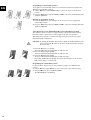
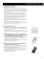
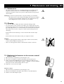
Elpro Electrol
Cinelpro
Compact Electrol
Cinema Electrol
SlimScreen Electrol
Elpro RF Electrol
Cinelpro RF Electrol
Compact RF Electrol
Cinema RF Electrol
VariVision Electrol
Instructions for use
Projecta electrical projection screens
EN - DE - FR - ES - NL - IT - RU
English
Deutsch
Français
Nederlans
Italiano
Русский
Table of contents
Page
EN
1. Unpacking ................................................................................................................................6
1.1. Opening the packaging ....................................................................................................................................................................................6
1.2. Packaging contents ...........................................................................................................................................................................................6
2. Safety information ..................................................................................................................7
Information for the consumer...............................................................................................................................................................................8
3. Function overview...................................................................................................................9
3.1. Wall switch ........................................................................................................................................................................................................9
3.2. RF remote control. Only with screens with built-in RF receiver ........................................................................................................9
3.3. IR remote control. Only with screens with built-in IR receiver ..........................................................................................................9
4. Installing the projection screen...........................................................................................10
4.1.
4.2.
4.3.
4.4.
Positioning the projection screen ..............................................................................................................................................................10
Wall or ceiling mounting ..............................................................................................................................................................................10
Connecting electrical projection screens.................................................................................................................................................11
Adjusting final position of electrical screens ...........................................................................................................................................12
5. Instructions for use ...............................................................................................................15
5.1.
5.2.
5.3.
5.4.
General instructions ......................................................................................................................................................................................15
Using the wall switch.....................................................................................................................................................................................15
RF remote control for screens with built-in RF receiver ....................................................................................................................15
IR remote control for screens with built-in IR receiver> ...................................................................................................................15
6. Potential problems and their solutions ..............................................................................16
7. Maintenance and cleaning....................................................................................................17
7.1. Maintenance.....................................................................................................................................................................................................17
7.2. Cleaning ............................................................................................................................................................................................................17
7.3. Replacing the batteries in the remote control .......................................................................................................................................17
8. Guarantee and guarantee conditions .................................................................................18
8.1.
8.2.
8.3.
8.4.
General provisions.........................................................................................................................................................................................18
Terms of guarantee .......................................................................................................................................................................................18
Exclusions from the guarantee....................................................................................................................................................................18
Guarantee provisions ....................................................................................................................................................................................18
9. Accessories ............................................................................................................................19
9.1. Mounting accessories ....................................................................................................................................................................................19
9.2. Operating accessories...................................................................................................................................................................................19
10. CE certification (Certification of compliance with European legislation) ...................................20
5
EN 1. Unpacking
1.1. Opening the packaging
Inspect the packaging first before opening it. If the packaging is damaged, we
recommend that you report this to your supplier. It is however very likely that,
despite slight damage to the packaging, your projection screen is still in good
condition.
1. Cut off the plastic straps.
2. Pull the tape off of the entire length.
S
Do not use a knife or other sharp object! If you do, you will risk damaging the screen or
the wiring.
3. Remove all of the components from the packaging; make sure that you do not
forget any of the components such as the small bags with mounting materials.
1.2. Contents of the packaging
In addition to the projection screen, you will always find a small bag with mounting
materials and any necessary accessories in each package. In addition, you should also
find these general instructions for projection screens in the packaging and a sheet
containing specific information which you will need for the installation and mounting
of the type of projection screen that you have purchased. On this sheet, for your
specific product, you will also find an overview of the contents of the packaging.
Check the contents of the packaging on the basis of this sheet. If you discover that
you are missing any components, contact your supplier.
6
2. Safety information EN
2.0.1 Read these instructions very carefully before installing or using the projection
screen. This is importnat in order to use the product safely and to prevent
personal injury or other damage.
2.0.2 Electrical connections should be performed by a qualified electrotechnical
fitter (electrician).
2.0.3 Confirm that the circuits which will be worked on are completely voltage-free
before the electrical connections are made.
2.0.4 See the plate on the projection screen for information on voltage and
maximum power capability.
If you stand facing the screen, you will find the type plate on the lower lefthand side of the back of the case.
T
T
2.0.5 If the projection screen is equipped with a pre-wired plug connection, the plug
must be accessible at all times.
2.0.6 The (wall) switch for the operation of the projection screen must be placed so
that the movements of the screen are visible, yet must remain out of the
range of the screen’s moving parts.
2.0.7 The (wall) switch for the operation of the projection screen must be mounted
at least 1.5 meters from the floor.
2.0.8 The projection screen may not be hung so that when in the down position, it
blocks the view of signs indicating the location of the escape routes nor may it
block access to the escape routes themselves.
2.0.9 The projection screen may not be hung in front of an air shaft or air
conditioner.
2.10
When installing electrically operated projection screens, use either the wall
switch with automatic zero position which comes with the screen, or a
comparable type of switch. The latter switch should only be used after
consultation with a qualifed electrotechnical fitter (electrician).
2.11
Standard mounting materials used for hanging the projection screen are
supplied with the screen. Each situation should however be evaluated
individually to determine if the materials supplied are satisfactory or if they
should be adapted to the specific situation. For example in situations involving
loose stucco, walls in poor condition or wall systems. In case of doubt, consult
a structural engineer.
2.12
Make sure that the walls and the structural construction are sturdy enough to
be able to support the weight of the projection screen. In case of doubt,
consult a structural engineer.
2.13
For mounting on the wall or ceiling, in addition to the mounting materials
supplied, specially developed accessories are available for use with alternative
mounting methods. See also section 9 ‘Accessories’. For further information,
consult your supplier.
2.14
If you discover damage to the screen’s wiring or case, discontinue the use of
the screen immediately and contact your supplier to repair the damage.
7
2.15
If the connection cable of the projection screen is damaged, the entire cable
must be replaced by a new cable or motor unit. These components are
available from the manufacturer or from the supplier.
2.16
Do not allow children to play with the screen. Mount the (wall) switch out of
reach of children or use a key switch (available as an accessory via your
supplier).
2.17
Projection screens wider than 5 meters must always be protected from
unauthorised use. For example, by using a key switch (available as an accessory
via your supplier). See section 4.3.3 ‘Connecting key switch’.
2.18
Keep all remote control devices out of the reach of children.
2.19
Use the wireless remote control only if you are able to observe the
movement of the screen. Never use the remote control if you are in another
room.
2.20
Make sure no one is standing under the projection screen while it is unrolling.
Also ensure that no one walks back and forth under the screen.
This also applies in cases where the projection screen has already been
unrolled.
2.21
The projection screens are not suitable for use in lift constructions above
stages or in theatres. Consult your supplier if you would like to use the
product in this type of situation.
2.22
All project projection screens are intended for indoor use only.
2.23
The projection screens must be hung drip and spatter free.
2.24
The projection screens may not be used in areas with a particularly corrosive
environment such as swimming pools, bathhouses or sauna rooms.
2.25
All of the projection screens are maintenance-free. For tips on cleaning and
maintenance, see section 7. ‘Maintenance and cleaning’.
EN
Information for the consumer
Disposal of your old product
Your product is manufactured from high-quality materials and components, which
may be recycled and reused.
If you see a symbol of a refuse container on wheels with a strike-through symbol on
your product, this means that the product falls under the EU guideline 2002/96/EC.
Find out how electrical and electronic products are collected separately in your area.
Observe local regulations when disposing of used products and do not place them
with the normal household refuse for collection. The proper disposal of used
products prevents negative consequences for the environment and public health.
8
3. Function overview EN
3.1. Wall switch
1 0 position
When the switch is set to zero, the motor is voltage-free.
2 3 4-switch
Allow the screen to unroll (4) and (3) retract.
3.2. RF remote control
Only with screens with built-in RF receiver (Elpro RF electrol, Cinelpro
RF electrol, Compact RF electrol, Cinema RF electrol)
1 Up button
Allows the screen to retract.
2 Stop button
– Stops unrolling/retracting.
– Programs new intermediate position.
– Deletes a pre-programmed intermediate position.
3. Down button
Allows the screen to unroll.
4 LED
Illuminates to confirm a command.
5 Program button
– Deletes program from remote control.
– Programs new (additional) remote control.
3.3. IR remote control
Only with screens with built-in IR receiver (VariVision electrol).
1 IR transmitter
Sends commands to the screen.
2 3-button
– Allows the screen to retract.
– Allows the screen to retract to a programmed intermediate position.
3 9-button
– Stops unrolling/retracting.
– Programs a new intermediate position.
4 4-button
Allows the screen to unroll.
9
EN 4. Installing projection screen
.4.1. Positioning projection screen
•
•
•
•
•
•
•
•
Determine where you would like to mount the screen beforehand. You may do
this with the aid of the information on the product specific information
sheet.Think carefully about the necessary space and the location of any electrical
connections.
The projector lens should preferably be positioned at a right angle to the vertical
line between the top and bottom of the screen.
The aspect ratio of the screen should correspond to the aspect ratio of the
projector.
Make sure that the projected image will fill the whole screen. This has to do with
the zoom factor of the projector.
There should not be any obstacles between the audience and the screen.
Make sure that the audience is seated within the range of the ideal viewing angle
for the screen. The ideal viewing angle is dependent upon the type of screen
fabric. For further information, see www.projectascreens.com.
For use in a living room (Home Cinema), maintain a height of 60 to 90 cm
between the floor and the bottom of the unrolled projection screen. This will
allow the audience to always see the full screen. For business use, a height of
approximately 125 cm is suggested.
Ambient light has a substantial effect on the image quality. For this reason, make
sure that there is no lighting equipment standing or hanging too close to the
screen and that no direct light falls on the screen. For an ideal projection quality,
it is best to darken the room.
4.2. Wall or ceiling mounting
•
•
Important! You are responsible for finding out (on your own or with the aid of a
structural engineer) whether modified mounting materials are necessary. For
example, if you would like to mount the screen to a wall system made from
plasterboard.
S
•
For the installation of an electrical screen, determine the location for the wall
switch. Install out of the reach of children and at a minimum height of 1.5 meters
from the floor.
•
Do not install the switch in the area where the projection screen is to be
unrolled. During the operation of the screen, the moving parts should be within
your field of vision so that you can check to see if anyone is standing within range
of these moving parts.
Special ceiling brackets are available as accessories for mounting the projection
screen to a false ceiling. See also section 9 ‘Accessories’ or ask your supplier.
A special wall bracket is available as an accessory for mounting the projection
screen at a certain distance from the wall (for example, if there is an obstacle in
the way). See also section 9 ‘Accessories’ or ask your supplier.
•
•
10
For mounting on wall or ceiling, it is best to use the mounting materials supplied
with the screen.
These materials have been tested and approved for the mounting of the
projection screen to concrete or brick constructions.
4.3. Connecting electrical projection screens
Important!
– The connection of the wiring may only be performed by a qualified electrotechnical fitter.
– Make sure that the circuits which will be worked on are completely voltage-free before
the electrical connections are made.
– Carefully read section 2 ‘Safety information’ first.
EN
S
T
4.3.1. Mounting wall switch
1 . First determine the position of the wall switch. Install out of the reach of children
and at a minimum height of 1.5 meters from the floor.
2. Loosen the rotary knob.
3. Unscrew the nuts under the rotary knob and remove the mechanism from the
case.
4. Mount the mechanism to the wall with two screws.
5. Replace the case and tighten the nuts.
6. Replace the rotary knob.
4.3.2. Wiring
General
1 = brown wire (L - live - voltage)
2 = yellow / green wire (e earth)
3 = blue wire (N - neutral)
4 = black wire (switch wire)
A plug may be connected to the feed wire when using the wall switch. The feed wires
may also be connected directly to the electric mains.
4.3.3. Electrical screens without built-in IR or RF remote control
(Elpro RF electrol, Cinelpro, Compact electrol, Cinema and
Slimscreen electrol)
1 Connect the various wires as shown in the diagram to the right.
2. Replace the case on the wall switch.
3. Plug the plug into the socket or apply voltage to the circuit concerned again.
•
In the event of incorrect rotation direction: ensure that the circuit involved is
voltage-free and swap the brown and black motor wires.
Important! It is not necessary to connect an earth wire with the SlimScreen electrol
screens. This is due to the double insulated motor.
4.3.4. Connect key switch
Projection screens wider than 5 meters must always be protected from unauthorised
use. This may be done by using a key operated switch.
Connect the various wires as shown in the diagram to the right.
11
4.3.5. Electrical screens with built-in IR or RF receiver
(Elpro RF electrol, Cinelpro RF electrol, Compact RF electrol,
Cinema RF electrol, VariVision electrol)
• Connect a plug (not included) and plug it into the socket.
• The screens may also be connected directly to the electric mains.
EN
S
Warning! Screens with a built-in remote control must be connected to the electric mains
using a plug. The plug must be easily accessible to ensure that the screen can be
made voltage-free if necessary.
4.4 Adjusting final position of electrical screens
The electrical screens come equipped with an automatic stop for unrolling and
retracting. The final positions (top/bottom) are adjusted during the production
process.
Top final position: screen fully retracted;
Bottom final position: screen fully unrolled.
These final positions may be adjusted manually by the user.
4.4.1. Electrical screens without built-in IR or RF remote control
(Elpro RF electrol, Cinelpro, Compact electrol, Cinema and
Slimscreen electrol)
• Test to make sure the screen unrolls and retracts.
• Turn the wall switch to the right (4) to allow the screen to unroll to the
bottom final position.
• Turn the wall switch to the left (3) to allow the screen to unroll to the top final
position.
1 Adjusting screw bottom final stop
Sets the bottom final position of the screen.
2 Adjusting screw top final stop
Sets the top final position of the screen.
Allow the screen to unroll further (bottom final stop):
• Turn the adjusting screw counterclockwise (to the left) to allow the screen to
unroll further (never more than 5 cm past the factory setting!). Use the hexhead
screw wrench to do this (no. 4).
• Test the new position by allowing the screen to unroll and then retract a short
distance.
Allow the screen to unroll a shorter distance (bottom final stop):
• Turn the adjusting screw clockwise (to the right) to allow the screen to unroll a
shorter distance. Use the hexhead screw wrench to do this (no. 4).
• Test the new position by allowing the screen to unroll and then retract a short
distance.
S
Important! If you allow the screen to retract too far, you risk damaging the screen and the
motor.
The screen may not retract into the case completely (top final stop):
• Turn the adjusting screw clockwise (to the right) 2 to allow the screen to retract a
shorter distance. Use the hexhead screw wrench to do this (no. 4).
12
The screen must retract further into the case (top final stop):
• Turn the adjusting screw counterclockwise to the left 2 to allow the screen to
retract further. Use the hexhead screw wrench to do this (no. 4).
Important! If you allow the screen to retract too far, you risk damaging the screen and the
motor.
4.4.2. Electrical screens with built-in RF receiver
(Elpro RF electrol, Cinelpro RF electrol, Compact RF electrol,
Cinema RF electrol)
• Check the final setting.
1. Press the Down button to unroll the screen.
2.Press the Up button to retract the screen.
Changing the top final setting
1. Allow the screen to retract completely by pressing the Up button quickly
once (1) .
2. Keep the Up button and the Down button depressed for 5 seconds
simultaneously.
– The screen will retract and unroll quickly in confirmation.
3. Use the Up button and the Down button to secure the screen in the desired
new final position.
4. Keep the Stop button depressed for 2 seconds in confirmation.
Changing the bottom final setting
1. Allow the screen to unroll completely by pressing the Downbutton quickly once.
2. Keep the Up button and the Down button depressed for 5 seconds
simultaneously.
– The screen will retract and unroll quickly in confirmation.
3. Use the Up button and the Down button to move the screen to the desired new
final position.
4. Keep the Stop button depressed for 2 seconds in confirmation.
EN
S
1
2
1
2
4
1
2
4
Programming an additional (second) remote control or wall transmitter
You can program an additional RF remote control or wall transmitter for operating
the screen.
Important! The Program button is located on the back of the remote control or wall
transmitter. Use a pen or paper clip to press the button.
S
1. Keep the Program button of the first remote control (already programmed)
depressed for 2 seconds.
– The screen will retract and unroll quickly in confirmation.
2. Press the program button of the extra remote control (still to be programmed)
quickly to program this for use.
Deleting the program of a remote control
If you have programmed a new remote control and would like to delete the old one,
for example if it is no longer functioning properly, you may delete the program from
the old remote control.
1. Keep the Program button of the newly programmed remote control depressed
for 2 seconds.
– The screen will retract and unroll quickly in confirmation.
2. Press the program button of the old remote control (to be deleted) quickly to
delete its program.
13
Programming an intermediate position
To program a new intermediate position, the old position must first be deleted. See
‘Deleting an intermediate position’.
1. Use the Up button and the Down button to move the screen to the desired
position.
2. Keep the Stop button depressed for 5 seconds .–The screen will retract and unroll
quickly in confirmation.
EN
1
1
2
Deleting an intermediate position
1. Press the Stop button once quickly to move the screen to the programmed
intermediate position.
2. Keep the Stop button depressed for 5 seconds .–The screen will retract and unroll
quickly in confirmation.
4.4.3. Electrical screens with built-in IR receiver (VariVision electrol)
The VariVision electrol screens are equipped with pre-programmed final positions.
Each final position is tailored for a certain image format: 4:3, 16:9 and 2.35:1
(Cinemascope for projection of extra wide images). These screens do not require
manual final position adjustment.
S
Important! In operating the VariVision electrol screens, always aim the IR transmitter of the
remote control at the IR receiver for the screen (located at the lower left of the
door of the case).
1.
–
2.
–
3.
–
•
Press the 4-button once quickly.
The screen will unroll to the final position for image size 4:3.
Press the 4-button again quickly.
The screen will unroll to the final position for image size 16:9.
Press the 4-button again quickly.
The screen will unroll to the final position for image size 2.35:1.
By pressing the 3-button (2) quickly, the screen will unroll back to the previous
final position (2.35:1 ➞ 16:9 ➞ 4:3).
Programming the intermediate position
For the VariVision electrol screens, it is possible to program one additional final
position.
1. Use the 3button and the 4button to move the screen to the desired position.
2. Keep the 9 button depressed for 5 seconds .
– The LED will light up in confirmation.
1
14
1
2
5. Instructions for use EN
5.1. General instructions
•
•
•
•
•
•
The projection screen is equipped with an electric tubular motor.
This simplifies the use of the screen.
The motor has been specially developed for this screen and ensures that the
screen unrolls and retracts with at a constant speed. The final positions may be
set on the motor. This has already been done at the factory. If you would like to
adjust the positions, follow the instructions found in section 4.4. Adjusting final
position of electrical screens.
As a result of this special construction, the motor has a limited continuous
duration of operation. For most motors, this duration is approximately
6 minutes. This long enough to allow the screen to unroll and retract several
times. However, if the screen is used continuously for too long, the motor will
become hot and the thermal overload cut-out will automatically turn off the
motor. Once the motor has cooled off sufficiently, it will turn back on
automatically. This can take 15 to 30 minutes.
Make sure that the screen is within your field of vision during operation so that
you can check to make sure that there are no persons or obstacles under the
screen.
Make sure that children are not able to play with the equipment involved in the
operation of the screen (wall switch, remote control).
Under normal use (once or twice daily) conditions, the life of the motor is at least
10 years. The motor does not require maintenance.
5.2. Use of the wall switch
•
•
Every electrically operated projection screen comes standardly equipped with a
rotary switch for mounting on the wall. After operation, the switch jumps back to
the zero position. This is an additional safety feature to make sure the motor is
always voltage-free when not in use.
Turn the switch to the right to unroll the screen and keep the switch in this
position until the screen is fully unrolled. Turn the switch to the left to retract the
screen.
5.3. RF remote control for screens with built-in
RF receiver (Elpro RF electrol, Cinelpro RF electrol,
Compact RF electrol, Cinema RF electrol)
•
•
•
The RF electrol screens come standardly equipped with an RF (Radio Frequency)
remote control. An RF module is also available as an accessory for use with the
other electrically driven projection screens.
The RF remote control works through walls and does not have to be aimed at a
specific object as is the case with an infrared system.
See also section 3.2 ‘RF remote control’.
5.4. IR remote control for screens with built-in
IR receiver (VariVision electrol)
•
•
•
The VariVision electrol screens come standardly equipped with a programmable
IR (infrared) remote control. An IR module is also available as an accessory for
use with the other electrically driven projection screens.
Many Audio/Video systems work with an IR remote control. There are also
programmable and intelligent IR system remote control devices available on the
market. These types of remote controls may be ‘taught’ or programmed to
operate the VariVision Electrol screen.
See also section 3.3 ‘IR remote control’.
15
EN 6. Potential problems and their solutions
T
Problems with the connections and wiring may only be repaired by a qualified fitter.
Problem
Solution
The screen does not unroll or
retract (anymore).
•
•
•
•
•
The screen/the motor made a
strange noise the first time I used
it.
•
•
The final position of the screen is
not adjusted properly.
•
•
The screen motor is turning in the
wrong direction (reverse direction).
16
•
Check for main voltage.
Check to make sure if the plug is plugged into the socket.
Check to see if the batteries are installed properly in the remote control. See also
section 7.3 Replacing the batteries in the remote control.
The thermal overload cut-out of the motor has been activated and has turned off
the motor. Wait 15 to 30 minutes and then try to unroll or retract the screen
again.
Make sure the screen is voltage-free and check the connections as described in
section 4.3 ‘Connecting electrical projection screens’. Check to see if any wires
are loose.
It is possible that an object (for example, part of the packaging) fell into the case
prior to mounting. Check to see if this is the case and whether this object is what
is causing the noise.
If the motor has been damaged during transport, please contact the supplier.
Adjust the screen according to the instructions in section 4.4 ‘Adjusting the final
position of electrical screens’.
If the factory settings are no longer present, this may be due to damage during
transport. If this is the case, contact the supplier.
Consult the connection diagrams in 4.3 ‘Connecting electrical projection screens’
and swap the brown and black motor wires.
Solution
7. Maintenance and cleaning EN
7.1. Maintenance
•
All of the projection screens are essentially maintenance-free. With electrical
projection screens however, we recommend checking the wiring and the
electrical connections at least once a year for ruptured cables and any exposed
cable insulation.
Warning! If you discover ruptured cables or any other defects, you should first
discontinue the use of the product immediately and contact your supplier
to arrange to have the damage repaired. Use only original parts for any
repairs. Original parts may be ordered from your supplier.
T
S
7.2. Cleaning
•
•
To clean the case, use a damp cloth and a soap-based cleaning product.
To remove stains on the projection screen fabric, use a damp cloth and a soapbased cleaning product. Use a soft cotton cloth which is lintfreefast and does not
give off lint. By preference, use a cloth which is a bit older and has been washed
often. Never rub one spot too long or too hard to prevent shiny spots from
developing.
If this method is unsuccessful, try to remove the stain with colourless ethyl
alcohol.
If this method is also unsuccessful, contact your supplier for advice.
Warning!
• Never use cleaning products which contain organic solvents such as benzine,
acetone, trichloroethylene, terpentine, etc.
• Never use cleaning products which contain abrasives, bleach or ammonia.
S
7.3. Replacing the batteries in the remote control
RF remote control
1. Open the battery compartment by unscrewing the cover.
2. Use a pen or screwdriver to slide the old battery from the battery box.
3. Slide a new 3V Lithium CR2430 battery into the battery box. Make sure you
insert the battery correctly bearing in mind the + indication on the box. Slide the
battery into the box until the battery clicks into place.
4. Replace the cover and screw it tight.
IR
1
2.
3.
remote control.
Open the battery compartment by unscrewing the cover.
Remove the old batteries and replace them with two 1.5 V AAA batteries.
Slide the cover back firmly into place.
17
EN 8. Guarantee and guarantee conditions
8.1. General provisions
•
•
•
These guarantee conditions are valid in the countries of the European Community
for 2 years from the date of purchase of the product.
The proof of purchase or invoice is valid as proof of the buyer’s right to claim
guarantee. A guarantee period of 2 years from the date of purchase is also valid in
all other countries.
These provisions are not intended to replace national laws, but exclusively as a
supplement to them.
8.2. Guarantee period
•
•
S
A guarantee period of 2 years is applicable to any manufacturer’s and construction
defects in the electrically driven projection screens.
A guarantee period of 5 years is applicable to the tubular motors of the
electrically driven projection screens.
8.3. Exclusions from the guarantee
The claim to guarantee is not applicable to:
a. Damage as a result of transport, falls or blows during transport, or shipping after
purchase.
b. The costs of the return transport as a result of the guarantee claim.
c. Defects or damage which have arisen as a result of improper use, misuse or use
by unauthorised persons, or due to the failure to follow indications from these
instructions for use.
d. Damage or defects resulting from inadequate mounting of the projection screen
to the wall or ceiling.
e. Damage or defects resulting from electrical connections made for the projection
screen which were not in accordance with the instructions for use.
f. Discolouration of the projection screen fabric, resulting from use in rooms with
considerable atmospheric pollution. For example dusty rooms and/or rooms in
which smoking is permitted.
g. Damage, discolouration of the lacquer or the projection screen fabric corrosion
resulting from exposure to humidity or a corrosive environment.
h. Damage or defects as a result of fire, earthquakes, floods or other natural
disaster, war or armed conflicts.
i. Damage or defects or which have arisen as a result of the use of the proejction
screen in installations or operating systems other than those accessories which
are supplied with the projection screen.
j. Damage or defects resulting from the application of non-original parts repairs
performed by third parties.
8.4. Guarantee provisions
18
•
If it appears that your product does not function properly or has stopped
functioning properly in spite of the fact that you have used it according to the
directions in these instructions, please contact the supplier of the product. Within
the valid guarantee period, the supplier may decide, in consultation with Projecta
b.v., to offer the product for repair or to replace it with the same or similar
product, all of this at the discretion of Projecta b.v.
•
Projecta b.v. does not accept any liability whatsoever for indirect damage,
consequential damage or other suffering to the user or buyer, arising from any
defects of the product nor for delays resulting from repairs or replacements of
the product. The statutory liability provisions remain in effect.
•
Upon Projecta b.v.’s request, the product shall be sent to Projecta b.v. for repair
or investigation. The costs of transport as well as the proper packaging of the
product do not fall under this guarantee scheme and are thus the responsibility of
the buyer. Damage occurring to the product as a result of transport for repairs or
investigation do not fall under the guarantee.
9. Accessories EN
Accessories help you to simplify the mounting and/or the operation of a projection
screen. For further information, please contact your supplier or Projecta b.v. or visit
our website: www.projectascreens.com.
9.1. Mounting accessories
Ceiling brackets
Special ceiling brackets are available for mounting a projection screen in a high room
or under a recessed ceiling. These brackets are 100 cm in length and may be
shortened as needed.
Wall brackets
In certain cases, it may be desirable to mount the projection screen a slight distance
from the wall. For example if the projection screen is to be hung in front of a
painting, or in order to prevent image distortion in cases where the projection screen
fabric has to be placed at an angle for overhead projection applications. See also ‘Wall
clamps’.
Wall clamps
The projection screen fabric may also be secured at an angle using wall clamps.
To do this, the slat bar may be simply clicked into the wall clamp.
9.2. Operating accessories
Infrared (IR) remote control
The infrared driven remote control consists of a surface-mounted outlet with infrared
receiver and hand transmitter.The surface-mounted socket must be connected to the
projection screen. The infrared receiver must be mounted so that it is visible to the
eye of the remote control. Using the remote control, the projection screen may be
operated from a distance of up to 7 meters.
Radio frequency (RF) remote control
The radio frequency remote control is a two-piece set consisting of a control module
and a hand transmitter.The control module must be connected to the projection
screen. Using the hand transmitter, the projection screen may be operated from a
distance of up to 30 meters.
19
EN 10. CE certificate
Declaration of conformity with European legislation
The product which you have received fully complies with all of the legal requirements
concerning electrical safety and consumer safety as specified by the European Union.
The manufacturer’s declaration below is evidence of this. In addition to this, the
manufacturer has taken all of the measures necessary to ensure the return of the
product at the end of its life and to destroy and dispose of it in a responsible manner.
20