1
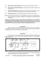
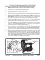
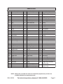
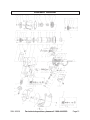
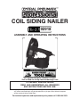
COIL SIDING NAILER
92918
ASSEMBLY AND OPERATING INSTRUCTIONS
®
3491 Mission Oaks Blvd., Camarillo, CA 93011
Visit our Web site at http://www.harborfreight.com
TO PREVENT SERIOUS INJURY,
READ AND UNDERSTAND ALL WARNINGS
AND INSTRUCTIONS BEFORE USE.
Copyright© 2005 by Harbor Freight Tools® . All rights reserved. No portion of this manual or
any artwork contained herein may be reproduced in any shape or form without the express
written consent of Harbor Freight Tools.
For technical questions and replacement parts, please call 1-800-444-3353.
Specifications
Item
Description
Fastener Length Capacity Plastic Collated
Wire Collated
Fastener Gauge
1-3/4" to 2-1/2" Long
1-1/4" to 2-1/2" Long
14-12 Gauge Nail Shanks .082"-.099" Diameter
Magazine Capacity
250-350 Nails
Operating PSI
70 to 125 PSI *
Air Consumption
12 CFM @ 90 PSI
Trigger Type
Single Sequential Safety Trip
Accessories
5 mm Hex Wrench, Pneumatic Tool Oil,
Coil of 300 Nails Included, Carrying Case
Unit Weight
8.22 Pounds
* The air pressure setting must not exceed job site regulations/restrictions. The air pressure setting
must not exceed 90 PSI when being used with work pieces that have a thickness of less than 1-3/4”.
Save This Manual
You will need this manual for the safety warnings and precautions, assembly,
operating, inspection, maintenance and cleaning procedures, parts list and assembly
diagram. Keep your invoice with this manual. Write the invoice number on the inside of the
front cover. Keep this manual and invoice in a safe and dry place for future reference.
Safety Warnings and Precautions
WARNING: When using tool, basic safety precautions should always be
followed to reduce the risk of personal injury and damage to equipment.
Read all instructions before using this tool!
1.
Keep work area clean. Cluttered areas invite injuries.
2.
Observe work area conditions. Do not use machines or power tools in damp or
wet locations. Do not expose to rain. Keep work area well lit. Do not use electrically
powered tools in the presence of flammable gases or liquids.
3.
Keep children away. Children must never be allowed in the work area. Do not let
them handle machines, tools, extension cords, or air hoses.
4.
Store idle equipment. When not in use, tools must be stored in a dry location to
inhibit rust. Always lock up tools and keep out of reach of children.
5.
Use the right tool for the job. Do not attempt to force a small tool or attachment to
do the work of a larger industrial tool. There are certain applications for which this
tool was designed. It will do the job better and more safely at the rate for which it
was intended. Do not modify this tool and do not use this tool for a purpose for
which it was not intended.
6.
Dress properly. Do not wear loose clothing or jewelry as they can be caught in
moving parts. Protective, electrically nonconductive clothes and nonskid footwear
REV 08/05 REV 11/06
SKU 92918
For technical questions, please call 1-800-444-3353.
Page 2
are recommended when working. Wear restrictive hair covering to contain long
hair.
7.
Do not overreach. Keep proper footing and balance at all times. Do not reach over
or across running machines or air hoses.
8.
Use eye and ear protection. Always wear ANSI approved impact safety
goggles and appropriate hearing protection. Wear a full face shield if you are
producing metal filings or wood chips. Wear an ANSI approved dust mask or
respirator when working around metal, wood, and chemical dusts and mists.
Other people in the work area must also wear ANSI approved impact safety
goggles.
9.
Maintain tools with care. Keep tools clean for better and safer performance. Follow
instructions for lubricating and changing accessories. Inspect tool cords and air
hoses periodically and, if damaged, have them repaired by an authorized technician.
The handle must be kept clean, dry, and free from oil and grease at all times. Do not
operate a tool if any portion of the tool’s operating controls are inoperable,
disconnected, altered or not working properly.
10.
Disconnect Air Hose and release any built-up air pressure. Never service the
Nailer, clear jams, or disassemble with the air hose attached. Always release any
built-up air even after disconnecting hose. Disconnect the Nailer when not in use.
11.
Remove adjusting keys and wrenches. Check that keys and adjusting wrenches
are removed from the tool or machine work surface before attaching to an air source.
12.
Avoid unintentional starting. Be sure the trigger is in the Off position when not in
use and before plugging in. Do not carry any tool with your finger on the trigger,
whether it is attached to an air source or not. Do not point the tool to wards yourself
or anyone whether it contains fasteners or not.
13.
Stay alert. Watch what you are doing, use common sense. Do not operate any tool
when you are tired.
14.
Check for damaged parts. Before using any tool, any part that appears damaged
should be carefully checked to determine that it will operate properly and perform its
intended function. Check for alignment and binding of moving parts; any broken
parts or mounting fixtures; and any other condition that may affect proper operation.
Any part that is damaged should be properly repaired or replaced by a qualified
technician. Do not use the tool if the trigger does not operate properly.
15.
Replacement parts and accessories. This product is to be repaired and serviced
only by a qualified technician. When this product is serviced, only identical
replacement parts should be used. Use of any other parts will void the warranty.
Only use accessories intended for use with this tool. Approved accessories are
available from Harbor Freight Tools.
SKU 92918
For technical questions, please call 1-800-444-3353.
Page 3
16.
Do not operate tool if under the influence of alcohol or drugs. Read warning
labels if taking prescription medicine to determine if your judgement or reflexes are
impaired while taking drugs. If there is any doubt, do not operate the tool.
17.
Use proper size and type extension cord. If an extension cord is required for the
air compressor, it must be of the proper size and type to supply the correct current to
the compressor without heating up. Otherwise, the extension cord could melt and
catch fire, or cause electrical damage to the tool. Check your air compressor’s manual
for the appropriate size cord. It is also possible that the use of an extension cord
may cause your circuit breaker to trip or your panel fuse to break. If this happens,
either use the compressor without an extension cord or find a larger amperage circuit
to use.
18.
Maintenance. The maintenance outlined in the maintenance section should be
performed regularly. For your safety, this product should be serviced or repaired
regularly only by a qualified technician.
19.
Compressed air only. Never use combustible gas as a power source.
20.
Do not load nails with the trigger or safety depressed. Unintentional
firing may occur. Do not load nails when the air hose is connected to the tool.
Always assume the tool contains fasteners.
21.
Disconnect air supply before loading the Nailer. Before reloading (or making
any adjustments to) the Nailer, make sure the compressed air is disconnected.
22.
Fire fasteners into an appropriate work surface only. Do not attempt to fire
fasteners into surfaces too hard to penetrate. Do not drive fasteners on top of other
fasteners, or at too steep an angle. Fasteners can ricochet causing personal injury.
Never fire the Nailer into the air, or point it toward yourself or another person. Always
wear ANSI approved safety goggles during use, maintenance, and reloading.
23.
Do not fire fasteners too close to the edge of a workpiece. They may split the
workpiece and fly free, causing personal injury.
24.
Take caution, as some woods contain preservatives such as copper chromium
arsenate (CCA) which can be toxic. When stapling or nailing these materials
extra care should be taken to avoid inhalation and minimize skin contact.
WARNING: Some dust created by power sanding, sawing, grinding, drilling, and
other construction activities contain chemicals known (to the State of
California) to cause cancer, birth defects, or other reproductive harm.
Some examples of these chemicals are:
* Lead from lead-based paints
* Crystalline silica from bricks and cement and other masonry products
* Arsenic and chromium from chemically treated lumber.
(California Health & Safety Code § 25249.5, et seq.)
SKU 92918
For technical questions, please call 1-800-444-3353.
Page 4
25.
Stay within air pressure capacity. Never operate the Nailer above 125 PSI.
26.
Hold tool away from head and body. During operation the Nailer may kick back
causing injury.
27.
Transport Nailer safely. Always disconnect air supply when moving the tool in the
workplace. Carry the tool by the handle to avoid contact with the trigger.
28.
Avoid working alone. If an accident happens, an assistant can bring help.
Note: Performance of the compressor (if powered by line voltage) may vary depending on
variations in local line voltage. Extension cord usage may also affect the tool
performance.
Warning: The warnings, cautions, and instructions discussed in this instruction
manual cannot cover all possible conditions and situations that may occur. It must
be understood by the operator that common sense and caution are factors which
cannot be built into this product, but must be supplied by the operator.
Unpacking
When unpacking, check to make sure all parts shown in the Parts List on page 13
are included. If any parts are missing or broken, please call Harbor Freight Tools at the
number on the cover of this manual as soon as possible.
Operation
For best service, you should incorporate an oiler, regulator, and inline filter, as shown
in the diagram below. Hoses, couplers, oilers, regulators, and filters are all available at
Harbor Freight Tools.
TO
ROOFING
NAILER
Note: To connect this tool, we recommend you use the included quick connector. For
smoother operation and to extend the life-span of the tool, put 3-5 drops of pneumatic
tool oil in the attached Air Inlet (61) before each use.
Rev 11/06
SKU 92918
For technical questions, please call 1-800-444-3353.
Page 5
Testing the Single Sequential Safety Trip Mechanism
Warning: Even though the nailer should be empty during this procedure,
ALWAYS point the nailer at a piece of scrap wood when testing.
1.
Make sure the tool is disconnected from the air supply.
2.
Completely empty the Nail Canister (100) of nails.
3.
The Nailer should not fire if the Safety (59) is not depressed against the workpiece.
4.
Make sure that the Trigger (51) cannot move with the Trigger Lock (28) in the
locked position. Rotate the Lock (28) to the unlocked position, as shown below
left. Make sure the Trigger (51) and Safety (59) move freely, without sticking.
5.
Connect the air supply to the tool at the Air Inlet (61). Set the regulator at the
recommended 70 PSI to 125 PSI, and set not to go over the maximum 125 PSI.
6.
Test the tool by depressing the Safety (59) against the workpiece without pulling the
Trigger (51). The Tool must not cycle (fire). If it cycles (fires), stop immediately
and have it repaired by a qualified service technician.
7.
Hold the tool away or off of the workpiece. The Safety (59) of the tool should return
to its original position. Squeeze the Trigger (51). The tool should not cycle (fire).
If the tool fires, stop immediately and have it repaired by a qualified service technician.
8.
Depress the Safety (59) against the workpiece and squeeze the Trigger (51). The
tool must cycle (fire) only once. Release the Trigger, slide the Safety (59) of the
tool over slightly, and squeeze the Trigger again. The tool must cycle (fire) only
once. With the Trigger held, carefully lift the nailer and press it against the workpiece
again. The tool must not cycle (fire). If it fails to perform in the manner explained
in bold, have it repaired by a qualified service technician.
TRIGGER
LOCK (28)
EXHAUST
COVER (2)
AIR INLET (61)
TRIGGER
(51)
SAFETY
(59)
Rev 11/06
SKU 92918
For technical questions, please call 1-800-444-3353.
Page 6
Loading Coil Nails
ALWAYS WEAR ANSI APPROVED IMPACT SAFETY GOGGLES WHEN
RELOADING OR DOING ANY OTHER MAINTENANCE ON THIS TOOL.
Other people in the work area must also wear ANSI approved impact safety
goggles.
Warning! Make sure the Nailer is not attached to the air hose whenever loading it.
1.
Rotate the Trigger Lock (28) to the locked position, as shown on page 6 and
below. To open the Canister (100), press down on the Door Latch (32) and swing
the Door (34) and Canister Cover (94) open.
2.
Check the Canister Platform (96) inside the Canister (100). The Platform can be
adjusted up and down to use various lengths of nails from 11/4”* to 21/2”:
A.
B.
C.
D.
*To help prevent jamming, nails under 13/4” must be wire collated.
For 11/4” to 11/2” Long Nails: Use first (top) setting
For 15/8” to 13/4” Long Nails: Use second setting
For 2” to 21/4” Long Nails: Use third setting
For 23/8” to 21/2” Long Nails: Use fourth (bottom) setting
3.
Place a coil of nails around the Canister Platform (96) in the Nail Canister (100).
4.
Uncoil enough nails to reach the Feed Pawl (87). Place the second nail on the coil
between the teeth of the Feed Pawl, making sure the nail head fits in the slot in the
upper portion of the Feed Pawl.
5.
Swing the Canister Cover (94) closed. Then, close the Door (34). Make sure the
Door closes securely. If it does not engage, the nail head is not in the slot in the
upper portion of the Feed Pawl (87).
TRIGGER LOCK (28)
LOCKED
FEED
PAWL (87)
NAILS
DOOR
(34)
CANISTER (100)
SKU 92918
CANISTER
COVER (94)
CANISTER PLATFORM (96)
(LIFT AND TURN
TO ADJUST)
For technical questions, please call 1-800-444-3353.
Page 7
Operating the Nailer
1.
Attach the Nailer to the air supply at the Air Inlet (61). Start your compressor and
check the pressure making sure it is set at the recommended 70-125 PSI and not to
go over the maximum 125 PSI.
2.
To fire, first rotate the Trigger Lock (28) to the unlocked position, as shown on page
6. Then, place the Safety (59) of the Nailer on the workpiece. The Nailer should not
fire if the Safety (59) is not depressed. Once depressed, gently and briefly squeeze
the Trigger (51) once. Do not fire repeatedly. Nails could bounce off one another,
damaging the workpiece or causing PERSONAL INJURY.
3.
If the nails are not being driven deeply enough or are being driven too deeply, then
adjust the Depth Adjuster (56). It make take some practice and experience to get
the desired results. If more depth adjustment is needed, the air supply pressure can
be adjusted, but ONLY within the recommended 70-125 PSI.
4.
The direction of the air exhaust can be changed by loosening the Exhaust Screw
(1) in the center of the Exhaust Cover (2), rotating the Exhaust Cover to the desired
direction and retightening the Exhaust Screw (1)
5.
Do not press the Safety (59) of the Nailer against the work surface with extra force.
Allow the tool to do the work. Always allow the tool to recoil off the workpiece.
6.
When finished using the Nailer, always rotate the Trigger Lock (28) to the locked
position and disconnect the tool from its compressed air supply. Empty the Nail
Canister (100) completely of nails. Attempt to fire the Nailer into a piece of scrap
wood to ensure it is disconnected and is incapable of firing any nails.
7.
Make sure to store the Nailer in its Carrying Case and in a clean, dry, safe location
out of reach of children.
Rev 11/06
SKU 92918
For technical questions, please call 1-800-444-3353.
Page 8
Anytime any maintenance or repairs are done (including clearing jams), FIRST:
1.
Disconnect the Nailer from the air hose.
2.
Empty the Nail Canister (100) completely.
3.
Attempt to fire the Nailer into a piece of scrap wood to ensure that it is disconnected and is incapable of firing any nails.
4.
Rotate the Trigger Lock (28) to its locked position as shown on page 6.
Clearing Jams
1.
Occasionally a nail may become jammed in the firing mechanism of the Nailer,
making the tool inoperable.
2.
To remove a jammed nail, rotate the Trigger Lock (28) to the locked position and
disconnect the Nailer from its compressed air supply. Empty the Nail Canister (100)
completely of nails. Ulock the Trigger Lock and attempt to fire the Nailer into a piece
of scrap wood to ensure it is disconnected and is incapable of firing any nails.
3.
Relock the Trigger Lock (28) and use a pair of needle nose pliers (not included) to
remove the jammed nail (usually from the Feed Pawl (87) area).
4.
Unlock the Trigger Lock and press the Safety (59) against a piece of scrap wood.
5.
Test fire the Nailer several times, checking for proper operation.
6.
If the Nailer is properly firing, you can continue to use the Nailer. Rotate the Trigger
Lock (28) to the locked position, disconnect the air supply to the Nailer, and reload
the Nails. Then, reconnect the air supply, disengage the Trigger Lock (28), and
continue working.
7.
When finished working, rotate the Trigger Lock (28) to the locked position and
disconnect the air supply. Remove the Nails. Then, store the Nailer and nails in a
location out of children’s reach.
TRIGGER LOCK (28)
LOCKED
DOOR
LATCH (32)
DOOR
(34)
CANISTER
COVER
(94)
CANISTER (100)
SKU 92918
For technical questions, please call 1-800-444-3353.
Page 9
1.
2.
3.
4.
Anytime any maintenance or repairs are done, FIRST:
Disconnect the Nailer from the air hose.
Empty the Nail Canister (100) completely.
Attempt to fire the Nailer into a piece of scrap wood to ensure that it is
disconnected and is incapable of firing any nails.
Rotate the Trigger Lock (28) to its locked position as shown on page 6.
Inspection, Maintenance, and Cleaning
1.
Inspect the Nailer frequently and lubricate periodically with Pneumatic tool oil, then
wipe dry. Do not use detergent oil or additives as these lubricants will cause
accelerated wear to the internal seals.
2.
Inspect the air supply filter, if present, before each use and clean or replace as
necessary. Dirt and water in the air supply filter are major causes of pneumatic tool
wear. Use a filter/oiler for better performance and longer tool life. The filter must
have adequate flow capacity for the specific application.
3.
Store the unit in a clean and dry location.
4.
All maintenance, service, or repairs not listed in this manual are only to be
attempted only by a qualified technician.
PLEASE READ THE FOLLOWING CAREFULLY
THE MANUFACTURER AND/OR DISTRIBUTOR HAS PROVIDED THE PARTS DIAGRAM IN THIS MANUAL AS A
REFERENCE TOOL ONLY. NEITHER THE MANUFACTURER NOR DISTRIBUTOR MAKES ANY REPRESENTATION
OR WARRANTY OF ANY KIND TO THE BUYER THAT HE OR SHE IS QUALIFIED TO MAKE ANY REPAIRS TO THE
PRODUCT OR THAT HE OR SHE IS QUALIFIED TO REPLACE ANY PARTS OF THE PRODUCT. IN FACT, THE
MANUFACTURER AND/OR DISTRIBUTOR EXPRESSLY STATES THAT ALL REPAIRS AND PARTS
REPLACEMENTS SHOULD BE UNDERTAKEN BY CERTIFIED AND LICENSED TECHNICIANS AND NOT BY
THE BUYER. THE BUYER ASSUMES ALL RISK AND LIABILITY ARISING OUT OF HIS OR HER REPAIRS TO THE
ORIGINAL PRODUCT OR REPLACEMENT PARTS THERETO, OR ARISING OUT OF HIS OR HER INSTALLATION
OF REPLACEMENT PARTS THERETO.
SKU 92918
For technical questions, please call 1-800-444-3353.
Page 10
PARTS LIST
Part
Description
Part
1
Exhaust Screw
36
Description
Part
Description
Spring
73*
Trigger Plunger
2
Exhaust Cover
37
O-ring
74*
O-ring
3
Screw
38
Spring
75*
Trigger Valve Cover
4
Washer
39
Pin
76
Retaining Ring
5
Cap
40
Spring
77
Piston
6
Gasket
41
Feed Pawl (b)
78
Piston Stopper
7
Ring
42
Small Feed Pawl
81
Spring
8
Head Cap
43
Screw
82
O-ring
9
Compression Spring
44
Split Washer
83
O-ring
10
Head Valve
45
Screw
84
Feed Piston
11
O-ring
46
Pin
85
Spring Guide
12
O-ring
47
Nose (Bottom Plate)
86
Spring
13#
Driver Nut
48
Trigger Lever
87
Feed Pawl (a)
14#
Washer
49
Pin
88
Pin Guide
15#
Piston Head
50
Pin
89
Spring
16#
O-ring
51
Trigger
90
Hook
17#
Driver
52
Sleeve
91
Pin
18
Cylinder Ring
54
Spring
92
Cover
19
Cylinder Ring
55
Tab
93
Nylon Inser t Nut
20
Cylinder
56
Depth Adjuster
94
Canister Cover
21
O-ring
57
O-ring
95
Platform Cap
22
Cylinder Ring
58
Retaining Ring
96
Platform
23
O-ring
59
Safety
97
Washer
24
Cylinder Plate
61
Air Inlet
98
Screw
25
O-ring
62
End Cap
99
Pin
26
Bumper
63
Filter
100
Canister
27
Rubber Grip
64*
Spring
101 Platform Spring
28
Trigger Lock
65*
Trigger Valve
102 Receiver (b)
29
Spring
66*
O-ring
103
30
Body
67*
O-ring
104 Hex Wrench (not shown)
Safety Goggles (not shown)
31
Shaft
68*
Pin
105
Tool Oil (not shown)
32
Door Latch
69*
O-ring
A1
33
Pin
70*
Valve Bushing
*Trigger Valve Assembly
(parts 64-75)
34
Door
71*
O-ring
A2
35
Pin Guide
72*
Trigger Valve Spring
#Driver Assembly
(parts 13-17)
NOTE: Some parts are listed and shown for illustration purposes only, and are not
available individually as replacement parts.
SKU 92918
For technical questions, please call 1-800-444-3353.
Page 11
ASSEMBLY DIAGRAM
SKU 92918
For technical questions, please call 1-800-444-3353.
Page 12