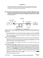
1
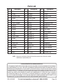
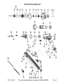
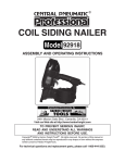
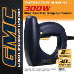
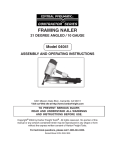
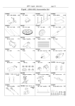
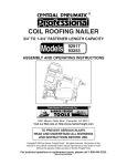
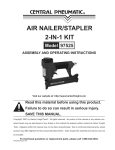
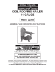
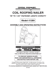
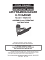
AIR FRAMING NAILER
8-10 GAUGE
Model 46240-B
ASSEMBLY and OPERATING
INSTRUCTIONS
3491 Mission Oaks Blvd., Camarillo, CA 93011
Visit our Web site at http://www.harborfreight.com
TO PREVENT SERIOUS INJURY,
READ AND UNDERSTAND ALL WARNINGS
AND INSTRUCTIONS BEFORE USE.
Copyright© 2003 by Harbor Freight Tools® . All rights reserved. No portion
of this manual or any artwork contained herein may be reproduced in any shape
or form without the express written consent of Harbor Freight Tools.
For technical questions and replacement parts, please call 1-800-444-3353
REV 06/04 REV 11/04
Specifications
28o, 0.113” - 0.131” Diameter
(8-10 Gauge), 2” - 3-1/2” long
Clipped Head Nails
Magazine Capacity
90
Air Inlet
1/4”- 18 NPT
Recommended Air Pressure
60-125 PSI *
Maximum Air Pressure
100 PSI
Safety Feature
Full Sequential Safety Trip Mechanism
This Nailer Features an Adjustable Depth Mechanism, see page 10.
Nail Size
* The air pressure setting must not exceed job site regulations/restrictions. The air
pressure setting must not exceed 90 PSI when being used with work pieces that have
a thickness of less than 1-3/4”.
Save This Manual
You will need the manual for the safety warnings and precautions, assembly instructions, operating and maintenance procedures, parts list and diagram. Keep your invoice with
this manual. Write the invoice number on the inside of the front cover. Keep the manual and
invoice in a safe and dry place for future reference.
Safety Warnings and Precautions
WARNING: When using tool, basic safety precautions should always be
followed to reduce the risk of personal injury and damage to equipment.
Read all instructions before using this tool!
1.
Keep work area clean. Cluttered areas invite injuries.
2.
Observe work area conditions. Do not use machines or power tools in damp or wet
locations. Do not expose to rain. Keep work area well lit. Do not use electrically powered
tools in the presence of flammable gases or liquids.
3.
Keep children away. Children must never be allowed in the work area. Do not let them
handle machines, tools, extension cords, or air hoses.
4.
Store idle equipment. When not in use, tools must be stored in a dry location to inhibit
rust. Always lock up tools and keep out of reach of children.
5.
Use the right tool for the job. Do not attempt to force a small tool or attachment to do
the work of a larger industrial tool. There are certain applications for which this tool was
designed. It will do the job better and more safely at the rate for which it was intended.
Do not modify this tool and do not use this tool for a purpose for which it was not intended.
6.
Dress properly. Do not wear loose clothing or jewelry as they can be caught in moving
parts. Protective, electrically nonconductive clothes and nonskid footwear are
recommended when working. Wear restrictive hair covering to contain long hair.
7.
Do not overreach. Keep proper footing and balance at all times. Do not reach over or
across running machines or air hoses.
8.
Remove adjusting keys and wrenches. Check that keys and adjusting wrenches are
removed from the tool or machine work surface before attaching to an air source.
REV 11/06
SKU 46240-B
For technical questions, please call 1-800-444-3353.
Page 2
9.
Use eye and ear protection. Always wear ANSI approved impact safety goggles
and appropriate hearing protection. Wear a full face shield if you are producing
metal filings or wood chips. Wear an ANSI approved dust mask or respirator
when working around metal, wood, and chemical dusts and mists. Other people
in the work area must also wear ANSI approved impact safety goggles.
10.
Maintain tools with care. Keep tools clean for better and safer performance. Follow
instructions for lubricating and changing accessories. Inspect tool cords and air hoses
periodically and, if damaged, have them repaired by an authorized technician. The handle
must be kept clean, dry, and free from oil and grease at all times. Do not operate a tool if
any portion of the tool’s operating controls are inoperable, disconnected, altered or not
working properly.
11.
Disconnect Air Hose and release any built-up air pressure. Never service the Nailer,
clear jams, or disassemble with the air hose attached. Always release any built-up air
even after disconnecting hose. Disconnect the Nailer when not in use.
12.
Avoid unintentional starting. Be sure the trigger is in the Off position when not in use
and before plugging in. Do not carry any tool with your finger on the trigger, whether it is
attached to an air source or not. Do not point the tool towards yourself or anyone whether
it contains fasteners or not.
13.
Stay alert. Watch what you are doing, use common sense. Do not operate any tool when
you are tired.
14.
Check for damaged parts. Before using any tool, any part that appears damaged should
be carefully checked to determine that it will operate properly and perform its intended
function. Check for alignment and binding of moving parts; any broken parts or mounting
fixtures; and any other condition that may affect proper operation. Any part that is damaged
should be properly repaired or replaced by a qualified technician. Do not use the tool if
the trigger does not operate properly.
15.
Guard against electric shock. Prevent body contact with grounded surfaces such as
pipes, radiators, ranges, and refrigerator enclosures.
16.
Replacement parts and accessories. This product is to be repaired and serviced only
by a qualified technician. When this product is serviced, only identical replacement parts
should be used. Use of any other parts will void the warranty. Only use accessories
intended for use with this tool. Approved accessories are available from Harbor Freight
Tools.
17.
Do not operate tool if under the influence of alcohol or drugs. Read warning labels
if taking prescription medicine to determine if your judgement or reflexes are impaired
while taking drugs. If there is any doubt, do not operate the tool.
18.
Use proper size and type extension cord. If an extension cord is required, it must be of
the proper size and type to supply the correct current to the compressor without heating
up. Otherwise, the extension cord could melt and catch fire, or cause electrical damage
to the tool. Check your air compressor’s manual for the appropriate size cord. It is also
possible that the use of an extension cord may cause your circuit breaker to trip or your
panel fuse to break. If this happens, either use the compressor without an extension
cord or find a larger amperage circuit to use.
SKU 46240-B
For technical questions, please call 1-800-444-3353.
Page 3
19.
Maintenance. The maintenance outlined in the maintenance section should be performed
regularly. For your safety, this product should be serviced or repaired regularly only by a
qualified technician.
20.
Compressed air only. Never use combustible gas as a power source.
21.
Do not load nails with the trigger or safety depressed. Unintentional
firing may occur. Do not load nails when the air hose is connected to the
tool. Always assume that the tool contains fasteners.
22.
Disconnect air supply before loading Nailer. Before reloading (or making any
adjustments to) the Nailer make sure that the compressed air is disconnected.
23.
Fire fasteners into an appropriate work surface only. Do not attempt to fire fasteners
into surfaces too hard to penetrate. Do not drive fasteners on top of other fasteners, or at
too steep of an angle. Fasteners can ricochet causing personal injury. Never fire the
Nailer into the air, or point it toward yourself or another person. Always wear ANSI
approved safety goggles during use, maintenance, and reloading.
24.
Do not fire fasteners too close to the edge of a workpiece. They may split the
workpiece and fly free, causing personal injury.
25.
Take caution as some woods contain preservatives such as copper chromium
arsenate (CCA) which can be toxic. When stapling or nailing these materials extra
care should be taken to avoid inhalation and minimize skin contact.
WARNING: Some dust created by power sanding, sawing, grinding, drilling, and other
construction activities, contain chemicals known [to the State of California] to
cause cancer, birth defects or other reproductive harm.
Some examples of these chemicals are:
• Lead from lead-based paints
• Crystalline silica from bricks and cement or other masonry products
• Arsenic and chromium from chemically treated lumber
(California Health & Safety Code § 25249.5, et seq. )
26.
Stay within air pressure capacity. Never operate the Nailer above 125 PSI.
27.
Hold tool away from head and body. During operation the Nailer may kick back causing
injury.
28.
Transport Nailer safely. Always disconnect air supply when moving the tool in the
workplace. Carry the tool by the handle and avoid contact with the trigger.
Note: Performance of the compressor (if powered by line voltage) may vary depending on
variations in local line voltage. Extension cord usage may also affect tool performance.
Warning: The warnings, cautions, and instructions discussed in this instruction manual
cannot cover all possible conditions and situations that may occur. It must be understood
by the operator that common sense and caution are factors which cannot be built into
this product, but must be supplied by the operator.
REV 11/06
SKU 46240-B
For technical questions, please call 1-800-444-3353.
Page 4
Unpacking
When unpacking, check to make sure the parts listed on page 10 are included.
If any parts are missing or broken, please call Harbor Freight Tools at the number
on the cover of this manual as soon as possible.
Warning! Disconnect the Nailer from the air compressor whenever loading or servicing.
After disconnecting the Nailer from the air compressor, there could still be enough
air pressure to fire the Nailer. Always fire the trigger repeatedly to make sure all of
the air is expended.
Set Up
1/4” Air Connector
(not included)
Nailer
1/4” -18 NPT
For best service you should incorporate an oiler, regulator, and inline filter, as shown in the
diagram above. Hoses, couplers, oilers, regulators, and filters are all available at Harbor
Freight Tools.
1. You will need to prepare a 1/4” air connector (sold separately) to connect to the Air Plug
(41) on the Nailer. First, wrap the 1/4” air connector (not included) with pipe thread seal
tape before connecting to the Air Source Hose (not included). Connect the Air Source
Hose to the Air Plug (41).
Note: If you are not using an automatic oiler system on your air compressor, before operation,
add a few drops of Pneumatic Tool Oil to the airline connection. Remove the air line at the
inlet and put 2 or 3 drops of good quality air tool oil into the air fitting each day of use. With
heavy, prolonged use, do this at least twice a day.
2. Set the air pressure on your compressor to 60-125 PSI. Do not exceed the maximum air
pressure of 125 PSI.
Note: About Air Consumption - CFM Air fastening tools are classified as “intermittent use”,
and, as such, may be operated by compressors of almost any size. Small, portable units
may not be suitable for high volume work, but will satisfactorily power the nailer for work at
a slower rate. The air demand of any fastening tool depends largely upon how quickly the
tool is to be used. PRESSURE - Use the lowest air pressure that will sufficiently drive the
fastener into the wood. This will depend on the density of the wood, and upon the size and
length of the nails being used. Vary the air pressure to adjust the driven depth, without
exceeding hte maximum air pressure of 125 PSI.
3. Check the air connection for leaks.
REV 11/06
SKU 46240-B
For technical questions, please call 1-800-444-3353.
Page 5
Testing the Full Sequential Safety Trip Mechanism
Warning: Even though the nailer should be empty during this procedure,
ALWAYS point the nailer at a piece of scrap wood when testing.
1.
Make sure the tool is disconnected from the power supply.
2.
Completely empty the Magazine (56) of nails.
3.
The Nailer should not fire if the Safety (28) is not depressed against the workpiece.
4.
Make sure the Trigger (31) and Safety (28) move freely, without sticking.
5.
Connect the air supply to the tool at the Air Plug (41). Set the regulator at the recommended 60 to 125 PSI.
6.
Test the tool by depressing the Safety (28) against the workpiece without pulling the
Trigger (31). The Tool must not cycle (fire). If it cycles (fires), stop immediately and
have it repaired by a qualified service technician.
7.
Hold the tool away or off of the workpiece. The Safety (28) of the tool should return to
its original position. Point the nailer in a safe direction, towards the scrap wood and
squeeze the Trigger (31). The tool should not cycle (fire). If the tool fires, stop immediately and have it repaired by a qualified service technician.
8.
Depress the Safety (28) against the workpiece and squeeze the Trigger (31). The tool
must cycle (fire) only once. Release the Trigger and squeeze it again. The tool must
not cycle (fire). With the Trigger held, carefully lift the nailer and press it against the
workpiece again. The tool must not cycle (fire). If it fails to perform in the manner
explained in bold, have it repaired by a qualified service technician.
Use the Correct Type of Nails
This nailer uses only “clipped-head” nails, which are collated at an angle of 28°. “Round
Head” nails, collated at 22°, are not to be used in this tool, as they will not feed reliably, and
may cause premature wear of the driver assembly.
Harbor Freight tools offers a variety of compatible fasteners, which are usually collated in
strips of 25. Nails from other manufacturers are also widely available from home centers and
building supply stores. Please note that some manufacturers offer fasteners packaged for
their brand of air nailers, and their nail strips may be longer than the loading slot in this tool.
REV 11/06
SKU 46240-B
For technical questions, please call 1-800-444-3353.
Page 6
Loading Nails
ALWAYS WEAR ANSI APPROVED IMPACT SAFETY GOGGLES WHEN
RELOADING OR DOING ANY OTHER MAINTENANCE ON THIS TOOL. Other
people in the work area must also wear ANSI approved impact safety goggles.
Always disconnect the air nailer from the air supply when loading the magazine. Grasp the
finger grip at the lower left side of the magazine, and pull the slide firmly back until it latches.
(See the photo section below.) Insert a strip of clipped-head nails, point down, into the loading
slot on top of the magazine. You may load 3, or more, strips, depending on the size of the nails.
When ready, pull rearward on the finger grip to relieve spring tension, and press the magazine
latch in to release the slide. Hold the slide grip to allow it to close gently.
Photo
1
Photo
3
1.
2.
Photo
2
Photo
4
Operating the Nailer
Attach the Nailer to the air supply at the Air Plug (41). Start your compressor and
check the pressure making sure it is set at the recommended 60-125 PSI and not over
the maximum 125 PSI.
After reading the following, it is recommended that you get acquainted with this tool by
practicing on scrap wood until you are familiar with its characteristics.
Always Wear Eye Protection When Using the Air Nailer
3.
4.
5.
Turn the Exhaust Cover (4) to direct the air away from the operator.
The full sequential trip trigger has a safety device assembled to the nosepiece. The
nailer will not fire unless the serrated collar is depressed. Never attempt to defeat
this mechanism, and never manually hold it back to shoot nails.
To place and shoot a single nail, grip the nailer without touching the trigger, and
position the nosepiece on the wood. With your free hand, press down on the top of the
nailer. Give the trigger a quick pull and release.
REV 11/06
SKU 46240-B
For technical questions, please call 1-800-444-3353.
Page 7
Anytime any maintenance or repairs are done (including clearing jams), FIRST:
1.
2.
3.
4.
1.
2.
3.
4.
Disconnect the Nailer from the air hose.
Empty the Magazine (56) completely.
Attempt to fire the Nailer into a piece of scrap wood to ensure that it is disconnected and
is incapable of firing any brads.
Always leave the Magazine (56) open during maintenance. The Magazine is springloaded and may cause parts or a nail to fly out of the Nailer.
Clearing Jams
Disconnect tool from air hose. Always fire the trigger repeatedly to make sure all of the
air is expended from the Nailer.
If a nail is jammed in the discharge area, simply remove it with pliers.
If a nail is jammed in the magazine, pull the Magazine Slide (47) all the way back to the
engaged position. Using a screwdriver, attempt to release the jammed nail by probing
either or both of the two openings in the magazine
(see photo below) to release the nail. Pull out the
jammed nail and the remainder of the nail strip that
is still in the magazine. Dispose of the remaining
nail strip; it may be bent or damaged in some other
way.
Reload the magazine with a new nail strip. Pull back
on the Magazine Slide (47) and with your other
hand pull the tab down on the Slide Release (58),
and guide the Magazine Slide (47) back into posiProbe in these areas with a
tion.
screwdriver to release jammed nails.
If you are unable to clear the nail jam using the method prescribed above, the tool should
be taken to a qualified service technician for proper servicing.
SKU 46240-B
For technical questions, please call 1-800-444-3353.
Page 8
Troubleshooting
Note: Have the following problems repaired by a qualified service technician.
Problem
Probable Cause
Solution
Air leaking at trigger
valve area.
D a m a g e d O - r i n g s i n t r i g g e r v a l v e Replace O-rings. Then, recheck safety trip
housing.
mechanism.
Air leaking between
housing and nose.
Loose screws in housing, damaged O- T i g h t e n s c r e w s , o r r e p l a c e O - r i n g s o r
rings or bumper.
bumper.
Air leaking between
housing and cap.
Loose screws or damaged gasket.
Runs slowly or has
power loss.
N a i l e r i n s u f f i c i e n t l y o i l e d , b r o ke n
Lubricate as instructed, install new spring, or
spring in cylinder cap, exhaust por t in
replace damaged internal par ts.
cap is blocked.
Tighten screws or replace gasket.
Worn or dir ty bumper, damaged pushR e p l a c e bu m p e r o r p u s h e r s p r i n g , c l e a n
er spring, inadequate air flow, worn or
bumper and dr ive channel, check fittings,
Nailer skips driving nails.
dry O-ring on piston, damaged O-ring
replace or lubricate O-rings, replace gasket.
on trigger valve, cap gasket leaking.
Nails are jammed in
nailer nose.
Guide on driver is worn. Wrong size or R e p l a c e g u i d e , u s e r e c o m m e n d e d , u n d a m a g e d n a i l s, l o o s e m a g a z i n e o r d a m a g e d n a i l s, t i g h t e n s c r ew s, r e p l a c e
nose screws, damaged driver.
driver.
Nail will not drive down
tight.
Replace blade, adjust air pressure, check
R o u n d e d d r i ve r b l a d e c a u s i n g s l i p spring under cap for broken coils or reduced
p a g e, p owe r l o s s, s l ow c y c l i n g a n d
l e n g t h , c h e ck i f c a p i n ex h a u s t p o r t i s
power loss.
restricted.
Driving nail too deeply.
Worn bumper or piston spacer.
Replace either or both par ts.
Warning! Disconnect the Nailer from the air compressor whenever loading or servicing. After disconnecting the Nailer from the air compressor, there could still be enough
air pressure to fire the Nailer. Always fire the trigger repeatedly to make sure all of the air
is expended.
Maintenance
Warning! Always disconnect the tool from the air compressor and then empty the magazine
of nails before attempting to inspect or perform maintenance to the Nailer. The following three
maintenance procedures can be done by the user of the tool.
1.
Inspect all of the nuts and screws and make sure they are securely fastened.
2.
Periodically lubricate the driving mechanism and magazine with a light oil. Wipe down
with a clean cloth. Never use gasoline or flammable solvents to clean the tool.
3.
Inspect your air compressor according to manufacturer’s instructions.
Warning! If you detect any air leaks, power loss, the Nailer skips driving, drives too
deep, or not deep enough, take the Nailer to a qualified service technician.
SKU 46240-B
For technical questions, please call 1-800-444-3353.
Page 9
Parts List
Part
Description
Part
Description
Part
Description
1
Screw
21
Bumper
42
Steel Bar
2
0-ring
22
Bumper
43
Screw
4
Exhaust Cover
23
Gasket
44
Catch Cover
5
Screw
24
Piston Guide
45
Screw
6
Exhaust Cover
25
Outlet Site
46
Suppor t
7
Piston Stopper
26
Screw
47
Magazine Slide
8
Washer
27
Spring
48
Nylon Nut
9
Spring
28
Safety
49
Screw
10
Gasket
29
Trigger Valve Set
50
Tail Cover
11
0-ring
31
Trigger
51
End Stopper
12
0-ring
32
Spring Pin
52
Screw
13
Piston Head
33
Spring Pin
53
Screw
14
0-ring
34
Spring Pin
54
Spacer
15
Piston Set
35
Screw
55
Spring
16
Piston Unit
36
Washer
56
Magazine
17
Air Seal
38
Nylon Nut
57
Front Stopper
18
Cylinder
39
0-ring
58
Slide Release
19
Cylinder Plate
40
Tail Cover
59
Ribbon Spring
20
Body
41
Air Plug
60
Handle Grip
NOTE: Some parts are listed and shown for illustration purposes only and are not available
individually as replacement parts.
PLEASE READ THE FOLLOWING CAREFULLY
THE MANUFACTURER AND/OR DISTRIBUTOR HAS PROVIDED THE PARTS DIAGRAM IN THIS MANUAL
AS A REFERENCE TOOL ONLY. NEITHER THE MANUFACTURER NOR DISTRIBUTOR MAKES ANY REPRESENTATION OR WARRANTY OF ANY KIND TO THE BUYER THAT HE OR SHE IS QUALIFIED TO MAKE
ANY REPAIRS TO THE PRODUCT OR THAT HE OR SHE IS QUALIFIED TO REPLACE ANY PARTS OF THE
PRODUCT. IN FACT, THE MANUFACTURER AND/OR DISTRIBUTOR EXPRESSLY STATES THAT ALL REPAIRS AND PARTS REPLACEMENTS SHOULD BE UNDERTAKEN BY CERTIFIED AND LICENSED
TECHNICIANS AND NOT BY THE BUYER. THE BUYER ASSUMES ALL RISK AND LIABILITY ARISING
OUT OF HIS OR HER REPAIRS TO THE ORIGINAL PRODUCT OR REPLACEMENT PARTS THERETO, OR
ARISING OUT OF HIS OR HER INSTALLATION OF REPLACEMENT PARTS THERETO.
SKU 46240-B
For technical questions, please call 1-800-444-3353.
Page 10
Assembly Diagram
SKU 46240-B
For technical questions, please call 1-800-444-3353.
Page 11