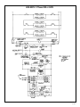
1
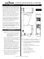
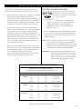
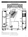
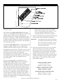
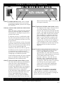
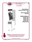
®
VENTILATOR HOOD
OPERATION & CARE MANUAL
VAE-30F
VPE-30F
VAE-55FS
MODELS: VPE-30F, VAE-30F, VAE-55F, -55FS
W 1 6 4 N 9 2 2 1 Wa t e r S t r e e t
PHONE: 262.251.3800
800.558.8744
PRINTED IN U.S.A.
●
P. O . B o x 4 5 0
U . S . A . / CA N A DA
●
Menomonee Falls , Wisconsin 53052-0450
FAX: 262.251.7067 - 800.329.8744
2 6 2 . 2 5 1 . 1 9 0 7 I N T E R N AT I O N A L
U . S . A . / CA N A DA
U.S.A.
WEBSITE:
w w w. a l t o - s h a a m . c o m
#8452/53/55 • 5/02
®
V E N T I L AT O R H O O D & F RY E R
SPECIFICATION INFORMATION
D E L I V E RY
15-13/16"
(401mm)
The Alto-Shaam fryer with ventilator hood has
been thoroughly tested and inspected to insure
only the highest quality unit is provided. When
you receive your unit, check for any possible
shipping damage and report it at once to the
delivering carrier. See Transportation Damage and
Claims section located in this manual.
DIMENSIONS
43-11/16" (1110mm)
The hood, complete with unattached items and
accessories, may be delivered in one or more
packages. Check to ensure that all items have
been received as standard with each unit.
VENTILATOR
POWER ON
CHECK
FILTERS
REPLACE
FILTER
SERVICE
REQUIRED
®
Save all the information and instructions packed
inside the unit. Complete and return the
warranty card to the factory as soon as possible
to assure prompt service in the event of a
warranty parts and labor claim.
76-3/8" (1940mm)
This manual must be read and understood by all
people using or installing this unit. Contact
your local Alto-Shaam distributor if you have
any questions concerning installation, operation,
and maintenance of this appliance.
®
36"—(914mm)
NOTE: All claims for warranty must include the
full model number and serial number.
U N PA C K I N G
1.
Carefully remove fryer with hood from the carton.
NOTE: Do not discard the carton and other
packaging material until you have
inspected the hood and fryer for
hidden damage and tested it for
proper operation.
2.
Read all instructions in this manual carefully
before installation of this hood and fryer.
Read and understand all labels and diagrams
attached to the equipment.
DO NOT DISCARD THIS MANUAL. This
manual is considered to be part of the fryer
and should be retained by the owner or
manager of the business, or to the person
responsible for training fryer operators.
Additional manuals are available from your
Alto-Shaam distributor. This manual is to be
used in conjunction with the manual for the
fryer associated with a ventilator hood.
3.
Remove all protective plastic film, packaging
materials and accessories from the hood and
fryer before the fryer is connected to
electrical power. Store accessories in a
convenient place for future use.
14-1/16"
(356mm)
23-3/8"
(594mm)
37-7/16" (950mm)
13"
(330mm)
NOTE: The ventilator hood is factory installed on the fryer.
Both appliances are shipped as a single unit.
The ventilator contains the following components:
1: Fire Suppression Agent Ansulex®R-102(HCS),
1.5 gallon (5,7 liters)
1: Fire Suppression Agent Tank
1: Fire Suppression System Charging Cartridge
1: Grease Receptacle
1: Stainless Steel Baffle Filter
1: Grease Vapor HEPA Filter
1: Odor Control Charcoal Filter*
*purchased separately as an option
1: literature package
Operation and Care Manual #8452/53/55
PG.
1
SAFETY PROCEDURES
Knowledge of proper procedures is essential to the safe
PRECAUTIONS & GENERAL INFORMATION
1.
This ventilator hood system is designed as part of a
operation of electrically energized equipment. In
deep fat fryer system. No other use of this product is
accordance with generally accepted product safety labeling
authorized or recommended.
guidelines for potential hazards, the following signal
words and symbols are used throughout this manual.
2.
This ventilator and attendant fryer are intended for
use in commercial establishments where all operators
Used to indicate the presence of a hazard
are familiar with the appliance use, limitations, and
which will cause severe personal injury,
associated hazards. Operating instructions and
death, or substantial property damage in
warnings must be read and understood by all
the event the statement is ignored.
operators and users.
Warning used to indicate the presence of a
3.
This ventilator hood system is designed to reduce odor
hazard which can cause personal injury and
emissions, but will not completely eliminate cooking
possibly death, or major property damage,
odors. Air exchange at the installation site must
in the event the statement is ignored.
comply with the requirements of the local
jurisdictional authority. To ensure that odors do not
Caution is used to indicate the presence of a
build up, recommended minimum air exchange is
hazard which will or can cause minor
400 cfm (11,3m 3) into and out of the site.
personal injury or property damage in the
event the statement is ignored.
4.
This equipment is made in the USA and has American
size hardware.
Used to indicate the presence of an
electrical hazard which will or can cause
5.
Any trouble shooting guides, component views or
personal injury or property damage in the
parts lists included in this manual are for general
event the statement is ignored.
reference only, and are intended for use by qualified
technical personnel.
NOTE
Note is used to notify personnel of
installation, operation, or maintenance
6.
This manual should be considered a permanent part of
information which is important but not
this appliance. The manual with all supplied
hazard related.
instructions, diagrams, schematics, part breakdowns,
notices, and labels must remain with the appliance if it
is sold or moved to another location.
HAZARD COMMUNICATION STANDARD (HCS)
The procedure in this manual may include the use of
chemical products. These chemical products will be
highlighted with bold face letters followed by the
abbreviation (HCS). See the Hazard Communications
Standard section of this manual for the appropriate
Material Safety Data Sheet(s).
EQUIPMENT SET-UP PRECAUTIONS
1.
Verify vertical clearances. Ventilator fryers require a
minimum of 96" (244cm) floor to overhead to allow for
adequate air circulation.
2.
Verify that the ventilator hood assembly is properly
and securely assembled to the fryer before beginning
the installation procedure.
3.
If a remote pull station is to be used, replace the rear
casters with fixed legs.
4.
Adjust the fixed legs with a spirit level until the unit
is level front-to-back and side-to-side.
Operation and Care Manual #8452/53/55
PG.
2
INSTALLATION & ELECTRICAL INFORMATION
Since the fryer is electrically powered, only a licensed
electrician should be used to connect power to the unit.
1.
2.
3.
Make certain this installation is in compliance with the
specifications listed in this manual, local code
requirements, and in accordance with the Standard for
Ventilation Control and Fire Protection of Commercial
Cooking Operations, NFPA-96 (current edition). These
requirements are the responsibility of the installer.
Certain codes require fryers to be restrained with a
tether or other restraint device. It is the responsibility
of the installer to check with the authority having
jurisdiction, in order to ascertain the applicability of
this requirement to this specific fryer installation. Any
restraint device must allow access to the back and
sides of the unit to provide service and maintenance
access, and must not interfere with the operation of
the fire suppression system.
Refer to the name plate on the front of the unit. The
electrical service power voltage and phase must match
the nameplate specifications and available electrical
service amperage must meet or exceed the
specifications listed. Wiring must be no less than 12
ga. solid copper wire, rated for at least 75°C.
ELECTRICAL SHOCK HAZARD
Electrical connections must be
made by a licensed electrician.
Electrical shock will cause death
or serious injury.
NOTE: Wire gauge, insulation type, and temperature
rating, as well as type, size, and construction of
conduit, must meet or exceed applicable
specifications of local codes of the National
Electrical Code.
4.
Fryers are shipped from the factory wired for 3-phase
service. Refer to 3-phase wiring diagram included
with this fryer and verify that field wiring conforms
with this diagram.
NOTE: Fryers are field convertible to 1-phase. If single
phase operation is required, refer to the 3-phase to
1-phase instructions included with the fryer. Verify
that both internal wiring and field wiring conform
to the single-phase wiring diagram included.
IMPORTANT: Fryer Models VAE-55 and VAE-55FS units
MUST NOT BE CONVERTED TO SINGLE
PHASE OPERATION. Conversion of these
units to single phase operation invalidates
the UL listing and voids the warranty.
ELECTRICAL SPECIFICATIONS
The hood is wired into the fryer
to provide a single electrical connection.
MODEL
VAC
KW
AMPS 1PH
AMPS 3PH
VPE-30F
208
9.0
43.3
25 per line
240
9.0
37.5
22 per line
308-415
9.3
N/A
15- L 1 , 13- L 2 & L 3
208
9.0
43.3
25 per line
240
9.0
37.5
21.7 per line
308-415
9.3
N/A
14.3-L 1 , 13-L 2, & L 3
208
17.0
N/A
47.8 per line
240
17.0
N/A
41.0 per line
308-415
17.4
N/A
26- L 1 , 24- L 2 & L 3
VAE-30F
VAE-55F(S)
Operation and Care Manual #8452/53/55
PG.
3
F I R E S U P P R E S S I O N S Y S T E M I N S TA L L AT I O N
FIRE HAZARD
The fire suppression
system must be installed,
activated, certified, and
maintained by an
authorized Ansul ® technician. Do not
attempt to modify or bypass the fire
suppression system. An uncontrolled
fire can cause serious injury or death.
FIRE SUPPRESSION AGENT
DISPENSING NOZZLE
(2 locations)
ALL MODELS REQUIRE A 280°F
(138°C) FUSIBLE LINK LOCATED
INSIDE HOOT BEHIND FILTERS
IMPORTANT
1. The fire extinguisher system must
be set up and charged by an
authorized Ansul ® technician.
The fryer is equipped with a
manual pull station at the lower
rear of the left side of the fryer.
The manual pull station must be in
a line of egress from the fryer. If
the fryer is installed in a location
where the factory installed manual
pull station is not accessible, an
additional remote pull station may
be required by local codes. Any
remote manual pull station must be
installed by an authorized Ansul
distributor in accordance with the
authority having jurisdiction.
2.
REMOVE HOUSING FOR ACCESS TO
FIRE SUPPRESSION SYSTEM. ACCESS
TO 450°F (232°C) FUSIBLE LINK ON VAE-55F(S)
REMOVE PANEL FOR ACCESS
TO FRYPOT. ACCESS TO 450°F
(232°C) FUSIBLE LINK ON VAE-30F
AND VPE-30F.
APPROXIMATE LOCATION
OF 450°F (232°C) FUSIBLE
LINK ON ALL MODELS.
BURN HAZARD • SPILLED OIL
The additional remote
pull station must not be
installed on the front
and/or sides of the fryer,
forward of the ventilator side panels.
Discharge of the fire suppression
system into hot oil will cause hot foam to spill over the
frypot. Serious burns may result from this spillage. Injury
from slipping or falling could also result.
The fire suppression system is comprised of a
pressurized container of Ansulex ® R-102 liquid fire
suppression media along with associated plumbing
and controls. The system utilizes two fusible links for
automatic actuation and a manual pull station for
manual actuation. Two nozzles are used to disperse
the dry chemical fire suppression media.
3.
NOTE: If the fire suppression system is discharged, a
buzzer will sound continuously. The fryer will
remain inoperable until the fire suppression
system is serviced, recharged, and reset by an
authorized Ansul ® distributor.
Charging the fire suppression system must be in
accordance with Ansul ® Design, Installation, Recharge
and Maintenance Manual #418086.
MANUAL FIRE
SUPPRESSION
PULL STATION
ON ALL MODELS.
4.
When the fire suppression system discharges, the fryer
heating element(s) and controls are de-energized and
the fire suppression media is discharged. The fire
suppression media will form an emulsion designed to
both smother and cool the oil.
The primary 450°F (232°C) fusible link is located on the
frypot. This link will melt and discharge the fire
suppression system in the event both the temperature
control thermostat and the high limit control fail. The
secondary 280°F (138°C) fusible link is located in the filter
plenum and will protect against a fire in the plenum.
Melting of either link will discharge the fire suppression
media through both nozzles and cause a buzzer to sound.
NOTE: As an additional fire safety detection device, the
Alto-Shaam fryer includes a sensor located within
the frypot to continuously measure the
temperature of the oil. In the unlikely event of a
simultaneous failure of both the thermostat and
the high limit switch, the sensor will automatically
activate the fire suppression system at
approximately 100°F (38°C) below the oil
temperature ignition point.
Operation and Care Manual #8452/53/55
PG.
4
F E AT U R E S & O P E R AT I N G C O N T R O L S
INDICATOR LIGHT PANEL
VENTILATOR
POWER ON
V. 2
CHECK
FILTERS
REPLACE
FILTER
V. 3
SERVICE
REQUIRED
V. 4
BACK VIEW
SIDE VIEW
V. 10
V. 6
V. 7
V. 5
FRON T V IE W
V. 8
V. 11
V. 12
V. 13
V. 14
V.1 7
V. 17
F.1
V. 15
F. 9
V. 16
F.1 8
V. 7
F. 19
F. 20
F.2 1
NOTE:
Items beginning with the letter "F" are components of the fryer.
Items beginning with the letter "V" are components of the ventilator.
Operation and Care Manual #8452/53/55
PG.
5
F E AT U R E S & O P E R AT I N G C O N T R O L S
F. 1 F RY E R P O W E R ON S W I T C H
Pressing the fryer switch to the ON position
illuminates the ventilator power ON light and
starts the blower. After approximately 10
seconds of operation in this condition,
sufficient air flow will be established to begin
fryer operation and the ventilator power ON
indicator will remain lit.
V. 2 VENTILATOR POWER ON INDICATOR (GREEN)
Illuminates when the fryer power switch is ON
and adequate air flow has been established.
V. 3 C H E C K F I LT E R S I N D I C AT O R ( A M B E R )
Illuminates when Odor Control filter or Grease
Vapor HEPA filter are missing or not properly
installed. When ON, the fryer heating elements
are de-activated and the fryer will not heat.
V. 1 0 V E N T I L AT O R E X H A U S T C O L L A R
Ventilator discharge outlet which includes a
fire damper with a fusible link which will
melt at a temperature of 165°F (74°C).
DO NOT BLOCK THIS OUTLET
V. 1 1 O D O R C O N T R O L F I LT E R
V. 1 2 G R E A S E VA P O R H E PA F I LT E R
V. 1 3 S TA I N L E S S S T E E L B A F F L E F I LT E R
See Filters Installation section in this manual.
V. 1 4 F I R E S U P P R E S S I O N S Y S T E M S TAT U S
I N D I C AT O R
Indicates current status of the Ansul Fire
Suppression System (i.e., cocked or fired).
V. 1 5 A U T O L I F T M O T O R A C C E S S
On VAE model fryers equipped with an
automatic basket lift device.
V. 1 6
V. 4 R E P L A C E F I LT E R S L I G H T ( A M B E R )
The "Replace Filter" light is directly tied to an air
flow diagnostic device which measures the air
pressure through the filter system. This light
will illuminate when the Grease Vapor filter and
the Odor Control filter accumulates a sufficient
amount of grease build-up to impede air flow.
This light is a clear indication to replace both
V. 1 7
filters. Failure to replace these filters within
approximately one week from the date the
"Replace Filter" light illuminates will result in
the illumination of the "Service Required"
indicator. Once the "Service Required" light is
illuminated, the fryer will become inoperable
F. 1 8
until both filters are replaced.
V. 5 S E RV I C E R E Q U I R E D L I G H T ( R E D )
This indicator will illuminate and the fryer will
be inoperable when there is insufficient
ventilator air flow due to grease laden filters.
V. 6 V E N T I L AT O R B L O W E R
Provides air flow through the ventilator system.
MANUAL FIRE SUPPRESSION
P U L L S TAT I O N
A remote fire suppression activation device
located on the lower left-hand portion of the
fryer body, at the back. This additional safety
feature can be activated manually if the
ANSEL auto-detection system fails in the
event of a fire.
G R E A S E R E C E P TA C L E
Catches grease and condensate dripping from
the Stainless Steel Baffle filter. Always
replace the empty container in the fryer to
avoid condensate from splattering and
draining into the oil.
G R E A S E D R I P PA N
Collection point for grease and condensation
funneled through a drain at the top of the
fryer. The condensate receptacle should
emptied at regular intervals.
Always replace the empty container in the
fryer to avoid condensate from draining into
the oil filter pan.
F . 1 9 S TA B I L I Z E R
V. 7 F U S I B L E L I N K L O C AT I O N S
Prevents the unit from tipping backwards.
Will melt at a predetermined set temperature to
F .20 RIGID (REAR) CASTERS
activate the fire suppression system.
Allows the unit to be easily positioned by
V. 8 F I R E S U P P R E S S I O N N O Z Z L E ( S )
slightly lifting the front of the unit.
Disperses the fire suppression media.
NOTE: If a manual fire suppression pull station is
F. 9 O I L F I LT E R P U M P
furnished, both rear casters (F.20) must be
replaced with legs to deter movement of the
MOTOR OVERLOAD RESET
fryer. Movement of an appliance which includes
Provides protection of the filter pump motor
a
remote pull station will discharge the fire
when fryer is over temperature. When tripped,
suppression
system media.
allow the fryer to cool and reset manually by
pressing inward.
F .21 FIXED (FRONT) LEGS
Operation and Care Manual #8452/53/55
PG.
6
VENTILATION HOOD FILTERS
The fryer ventilation hood consists of a three-part
filtration system.
The carbon based, Odor Control Filter will reduce
odors to an acceptable level through the extraction of
airborne grease. While the use of this filter is
optional, utilization is strongly recommended when
frying on a regular basis This charcoal filter should
be lifted into place against the stainless steel flanges,
directly in front of the exhaust blower, and dropped
into the proper channel.
The Grease Vapor HEPA Filter is a high-temperature
fiberglass medium, tightly woven to capture the
smallest particles of grease vapor as the air flows
through the exhaust system. This filter is one of two
individual filters directly interlocked with the fryer.
If this filter is not in place or not properly
positioned, the fryer will not operate. The Grease
Vapor HEPA filter should be lifted into place behind
the "Odor Control" filter and dropped into the
proper channel.
The two preceding filters are followed by the
Stainless Steel Baffle Filter which is designed to
extract larger grease particles as the air flows
through the system. This filter will also increase the
life of the Odor Control filter and the Grease Vapor
filter. Again, this filter is directly interlocked with
the fryer and if not in place nor properly positioned,
the fryer will not operate. When lifting this filter
into place, it is important to make certain it makes
contact with the electronic interlock switch which
activates the fryer. Unlike the other two filters, the
Stainless Steel Baffle filter is washable and should be
cleaned on a regular basis.
NOTE: When in proper position, the Grease Vapor
HEPA filter and the Stainless Steel Baffle
filter actuate magnetic reed switches. They
must be properly installed or the fryer
heating element(s) will not be energized.
1.
Remove the protective plastic bag from the optional
charcoal, odor control filter before installing.
WARNING:
2.
Installing the filter without removing
the plastic bag will block the air flow.
This will cause the ventilator to shut
down 10 seconds after start-up and
the fryer will not heat.
Note the air flow direction arrow on each filter,
and verify that the arrow points toward the
plenum when the filter is installed. Install by
inserting the top of each filter into the top filter
support inside the hood assembly. Pivot the
bottom of each filter toward the rear of the hood
assembly and drop it into its respective bottom
filter support. Seat each filter firmly into the
bottom filter support.
ODOR CONTROL FILTER:
19-1/2" x 14" x 7/8"
(495mm x 356mm x 22mm)
GREASE VAPOR HEPA FILTER:
19-1/2" x 15-1/2" x 3-3/4"
(495mm x 394mm x 95mm)
STAINLESS STEEL BAFFLE FILTER:
19-1/2" x 15-1/2" x 1-5/8"
(495mm x 394mm x 41mm)
Operation and Care Manual #8452/53/55
PG.
7
GREASE RECEPTACLE & GREASE DRIP PAN
Cooking vapors produced by frying, particularly pressure frying, will condense and accumulate on the
stainless steel surfaces of the hood. The ventless hood is designed to collect some of this condensation in a
grease receptacle located directly under the Stainless Steel Baffle filter. Additional accumulation is collected
at the top of the fryer and is funneled through a drain at the top of the fryer into a collection receptacle
located at the bottom of the unit. Both condensate receptacles should be emptied at regular intervals,
however, it is important to replace the empty containers in the fryer to avoid condensate from draining into
hot oil or the oil filter pan.
Install the grease receptacle (V.17) into the brackets
1.
directly below the Stainless Steel Baffle filter.
NOTE: Operation of the fryer without replacing the
grease receptacle in the proper position will
2.
Install the drip pan (V.18) into the mounting
bracket behind the fryer door at the lower right
front of the fryer.
NOTE:
Failure to install the grease drip pan will
cause accumulated fryer cooking grease and
allow grease, moisture, and other liquids
condensation to drip directly into the frypot oil.
that accumulate on the fryer top panel to
BURN HAZARD • HOT OIL SPLATTER
Do not operate unless grease
receptacle is installed. Moisture
will drip into hot oil in the
drip onto the floor causing both a safety
hazard and a health hazard.
SLIPPING & FALLING HAZARD
• SPILLED OIL
frypot causing hot oil splatter.
Do not operate unless the drip pan
Serious injury will result from
is installed. Oil will drip onto
contact with hot oil.
the floor and falls will result.
Death or serious injury may result
from slipping and falling in spilled oil.
Operation and Care Manual #8452/53/55
PG.
8
C O N T R O L S • F U N C T I O N S • O P E R AT I O N
FRYER
CONTROL PANEL
ITEM
POWER SWITCH ( FRYER •
ITEM
VENTILATOR POWER ON INDICATOR
When the check filters light is off, the fryer
will operate normally.
• FILTER )
Pressing the switch on the fryer control
panel to the "FRYER" position will energize
the ventilator.
OFF
ITEM
The "Replace Filter" light is directly tied to
an air flow diagnostic device which
measures the air pressure through the filter
system. This light will illuminate when the
Grease Vapor filter and the Odor Control
filter accumulates a sufficient amount of
grease build-up to impede air flow. This
light is a clear indication to replace both
filters. While the fryer will still operate
normally, the air filter must be changed in
a timely manner or the service required
light will illuminate and the fryer will not
operate until the air filters have been
replaced.
( GREEN )
When the fryer is energized, the ventilator
power ON indicator light will illuminate
and the blower will begin to operate for a
period of 10 seconds.
If sufficient air flow is established within
this 10 second period, the power on light
will remain illuminated and the fryer will
be operational.
If there is not sufficient air flow for proper
operation within this 10 second period, the
blower and ventilator power light will turn
OFF , the service required light will
illuminate, and the fryer will not operate.
Insufficient air flow requires the operator
to switch the fryer control to the OFF
position for a short period of time before
attempting to reestablish operation.
Under normal operation, the green ventilator
power ON indicator will be the only light
illuminated on the ventilator panel.
ITEM
CHECK FILTERS INDICATOR ( AMBER )
The check filters indicator will illuminate
when the Grease Vapor HEPA filter is
missing or not properly installed or the
Stainless Steel Baffle filter is not properly
installed. When the check filters light is
illuminated, the fryer is inoperable.
If the check filters light illuminates, check
both the Stainless Steel Baffle filter and
Grease Vapor HEPA filter for proper
installation. Always replace the HEPA
filter and charcoal filter at the same time.
REPLACE FILTERS INDICATOR ( AMBER )
ITEM
SERVICE REQUIRED INDICATOR ( RED )
Failure to replace Odor Control and the
Grease Vapor HEPA filters within
approximately one week from the date the
"Replace Filter" light illuminates will result
in the illumination of the "Service
Required" indicator. Once the "Service
Required" light is illuminated, the fryer
will become inoperable until both filters
are replaced. Once the filters are replaced,
reset the fryer by pressing the power
switch to the OFF position, immediately
followed by pressing the switch of the
Fryer to the ON position.
SERVICE POWER FAILURE
If the shutdown is caused by a service power
failure, the fryer can be restarted by cycling the
power switch to OFF and then ON .
The Ventilator Hood manual is to be used in conjunction with the fryer manual supplied with this product.
Operation and Care Manual #8452/53/55
PG.
9
VENTILATOR CLEANING INSTRUCTIONS
DAILY CLEANING
MONTHLY CLEANING
Wash the exterior of the
ventilator hood with
warm water, mild soap
or detergent, and a
clean, nonabrasive cloth a
minimum of once
a day. Rinse
with clean, warm
water and dry
with a clean,
non-abrasive cloth.
WEEKLY CLEANING
Remove the grease receptacle and grease drip
pan and empty both containers. Remove the
Stainless Steel Baffle filter. Wash and rinse the
baffle filter, grease receptacle, and grease drip
pan in the sink or dishwasher using mild degreasing detergent and warm water. Dry with a
clean, non-abrasive cloth.
Cover the frypot. Remove the Grease Vapor
HEPA filter and optional, Odor Control charcoal
filter. Wash the interior of the ventilator with
warm water, a mild soap or detergent and a
clean, non-abrasive cloth. Dry thoroughly with a
clean, dry non-abrasive cloth.
In the USA, use and maintenance shall be in
accordance with the current edition of the
Standard for Ventilation Control and Fire
Protection of Commercial Cooking Operations,
NFPA 96.
NOTE: A signed and dated Fryer Hood Maintenance
Log must be maintained on the premises and
shall be available for use by the authority
having jurisdiction.
See sample in the back of this manual.
REQUIRED VENTILATOR MAINTENANCE
THREE MONTH MAINTENANCE
Clean the entire hood plenum and blower section.
SIX MONTH MAINTENANCE
1.
Inspection and testing of total operation
including fire damper and all safety interlocks
shall be performed by qualified service personnel.
ANNUAL MAINTENANCE
The fusible links for the fire suppression system
must be replaced. Nozzles and manual pull
station must be cleaned in accordance with
Ansul ® R-102 System Design, Installation,
Recharge and Maintenance Manual (#418087).
TWELVE YEAR MAINTENANCE
2.
All fire suppression system actuation
components including manual pull station and
any remote manual pull station must be
inspected for proper operation in accordance
with the maintenance schedule published in
Ansul ® R-102 System Design, Installation,
Recharge and Maintenance Manual (#418087).
3.
On VAE Model fryers, open the rear cover access
door and lubricate the lift worm threads with
moly (molybdenum disulfide) grease.
The fire suppression agent tank and 1/4"
(6,4mm) flex hose must be hydrostatically tested.
The fire extinguishing agent must be replaced in
accordance with the maintenance schedule
published in Ansul ® R-102 System (Standard
UL300 listed). This maintenance is to be
performed by authorized Ansul ® service
personnel only.
Operation and Care Manual #8452/53/55
PG.
10
TROUBLESHOOTING
The filters are the only owner-serviceable components of the ventilator hood system. For any other problem which
cannot be remedied by servicing the filters, contact an authorized fryer or ventilator service agency. Contact an
authorized Ansul ® distributor for service of the fire suppression system.
PROBLEM
REMEDY
Unit will not operate.
Circuit breaker is tripped. Reset breaker. If tripping persists,
contact a licensed electrician for repair of field wiring or contact
an authorized service agency for repairs.
A buzzer sounds continuously and unit
will not operate.
Ansul ® system has tripped. Contact an
authorized Ansul ® agent for service and repairs.
Check Filters light is illuminated.
Grease Vapor HEPA filter missing or not in the proper position.
Make certain both the HEPA filter and Stainless Steel Baffle filter
are properly installed in their respective rails.
Replace Filters light is illuminated.
Grease Vapor HEPA filter or charcoal filter nearing the end of
their service life. Be sure to have proper replacement filters on
hand. Always replace the HEPA filter and charcoal filter at the
same time.
Service Required light is illuminated.
Grease Vapor HEPA filter or charcoal filter is plugged.
Replace filters.
— Fire damper on exhaust color has closed. Contact authorized
service agency for repairs.
One or more vacuum sensing lines are plugged. Contact an
authorized service agency for repairs.
NOTE: After 10 seconds, if there is not sufficient air flow for proper operation, the service required light will
turn ON and the fryer will be de-energized. The power switch must be turned OFF to reset the system
before the fryer can be operated.
SERVICE PARTS LIST
IMPORTANT: Use only factory authorized service parts
and replacement filters. Contact the
Alto-Shaam service department for
specific information.
NORMAL MAINTENANCE ITEMS
Odor Control Charcoal Filter
Grease Vapor HEPA Filter
Stainless Steel Baffle Filter
Leg Assembly
IMPORTANT: Parts used for the Ansul ® fire suppression
system are not serviceable by the
owner/operator. Procedures for servicing
fire suppression equipment are described
in the Ansul ® R-102 System Design,
Installation, Recharge and Maintenance
Manual (#418087). This manual is
intended for use by authorized service
personnel only.
HAVE THE FOLLOWING INFORMATION AVAILABLE
WHEN CALLING FOR SERVICE
C U S TO M E R S E RV I C E DATA
PURCHASED FROM:______________________________________
DATE INSTALLED:_______________________________________
INSTALLATION TECHNICIAN:________________________________
EQUIPMENT MODEL NUMBER:______________________________
EQUIPMENT SERIAL NUMBER:
Voltage:
______________________________
208V
AUTHORIZED SERVICE AGENCY:
240V
308-415V
____________________________
ADDRESS:____________________________________
_____________________________________
PHONE:______________________________________
Operation and Care Manual #8452/53/55
PG.
11
Operation and Care Manual #8452/53/55
PG.
12
Operation and Care Manual #8452/53/55
PG.
13
Operation and Care Manual #8452/53/55
PG.
14
Operation and Care Manual #8452/53/55
PG.
15
Operation and Care Manual #8452/53/55
PG.
16
Operation and Care Manual #8452/53/55
PG.
17
Operation and Care Manual #8452/53/55
PG.
18
Operation and Care Manual #8452/53/55
PG.
19
Operation and Care Manual #8452/53/55
PG.
20
Operation and Care Manual #8452/53/55
PG.
21
Operation and Care Manual #8452/53/55
PG.
22
Operation and Care Manual #8452/53/55
PG.
23
Operation and Care Manual #8452/53/55
PG.
24
Operation and Care Manual #8452/53/55
PG.
25
Clean Manual Pull
☛
Station and any
Remote Manual Station
(max. interval: 12 months)
Clean Discharge Nozzle ☛
in Plenum after Filters
(max. interval: 12 months)
Clean Discharge Nozzle ☛
in Plenum before Filters
(max. interval: 12 months)
Replace Fusible Link ☛
on Frypot
(max. interval: 12 months)
Replace Fusible Link in ☛
Hood Plenum
(max. interval: 12 months)
Replace Fusible Link in ☛
Flue Damper
(max. interval: 12 months)
Inspect/Test
☛
Filter Interlocks
(max. interval: 6 months)
☛
Inspect/Test
Fire Suppression
System
(max. interval - 6 months)
Replace HEPA Air Filter
& Charcoal Air Filter
(as required)
Clean Plenum Grease
Baffle and Blower
(max. interval - 3 months)
OPERATION
Date/Agent
Date/Agent
Date/Agent
Date/Agent
Date/Agent
Date/Agent
Date/Agent
☛ To be Performed by Qualified Service Personnel Only.
Date/Agent
FRYER HOOD MAINTENANCE LOG
Date/Agent
Date/Agent
Date/Agent
Date/Agent
Date/Agent
Operation and Care Manual #8452/53/55
PG.
26
Operation and Care Manual #8452/53/55
PG.
27
F RY E R
Original Equipment
Limited Warranty
T R A N S P O RTAT I O N
DA M AG E A N D C L A I M S
All Alto-Shaam equipment is sold F.O.B.
shipping point, and when accepted by the carrier,
such shipments become the property of
the consignee.
Alto-Shaam, Inc. warrants to the original purchaser that any original part that is
found to be defective in material or workmanship will, at our option, subject to
provisions hereinafter stated, be replaced with a new or rebuilt part.
Should damage occur
in shipment, it is a
matter between the
carrier and the consignee.
In such cases, the carrier is
assumed to be responsible for the safe delivery of
the merchandise, unless negligence can be
established on the part of the shipper.
1.
2.
Make an immediate inspection while the
equipment is still in the truck or immediately
after it is moved to the receiving area. Do not
wait until after the material is moved to a
storage area.
Do not sign a delivery receipt or a freight bill
until you have made a proper count and
inspection of all merchandise received.
3.
Note all damage to packages directly on the
carrier’s delivery receipt.
4.
Make certain the driver signs this receipt. If he
refuses to sign, make a notation of this refusal
on the receipt.
5.
6.
If the driver refuses to allow inspection, write
the following on the delivery receipt:
Driver refuses to allow inspection
of containers for visible damage.
Telephone the carrier’s office immediately upon
finding damage and request an inspection. Mail
a written confirmation of the time, date, and the
person called.
The labor warranty remains in effect one (1) year from installation or fifteen (15)
months from the shipping date, whichever occurs first. Alto-Shaam will bear
normal labor charges performed during standard business hours not subject to
overtime, holiday rates, or any additional fees.
The parts warranty remains in effect one (1) year from installation or fifteen (15)
months from the shipping date, whichever occurs first.
This warranty does not apply to:
1.
Safety thermostat, circuit breaker and overload protector reset or fuse
replacement unless specifically warranted.
2.
Any and all malfunction due to operation at voltages other than specified
on the equipment. Conversion to correct voltage and phase are the
responsibility of the purchaser.
3.
Any and all problems due to electrical connections not in accordance with
electrical code requirements and the wiring diagrams supplied with the
equipment.
4.
Calibration of heat controls on original components after the first sixty
(60) days.
5.
Replacement of items subject to normal wear. Such items include but are
not limited to knobs, light bulbs, baskets, grids, mechanical timers,
thermocouples, fuses and indicating lights.
6.
Normal maintenance functions including lubrication, adjustments of air-flow,
thermostats, door mechanisms, microswitches, burners and pilot burners.
7.
Installation labor, inspection, and start-up are not considered warranty items.
8.
Charges incurred by delays or operational restrictions which hinder the ability
of a service technician to perform service are not covered by warranty.
9.
Equipment damage caused by accident, shipping, improper installation or
alteration.
10. Equipment used under conditions of abuse, misuse, carelessness or
abnormal conditions including equipment subjected to harsh or
inappropriate chemicals, poor water quality or equipment with missing or
altered serial numbers.
11. Any losses or damages resulting from malfunction, including loss of
product or consequential or incidental damages of any kind.
7.
Save any packages and packing material for
further inspection by the carrier.
12. Equipment modified in any manner from original model, substitution of
parts other than factory authorized parts, removal of any parts or
addition of any parts.
8.
Promptly file a written claim with the carrier
and attach copies of all supporting paperwork.
Alto-Shaam factory authorized replacement parts are warranted for ninety
(90) days from date of purchase on non-warranty equipment. Replacement
parts warranty is limited to the defective part only. The use of parts other
than factory authorized Alto-Shaam replacement parts completely voids
warranty coverage.
We will continue our policy of assisting our
customers in collecting claims which have been
properly filed and actively pursued. We cannot,
however, file any damage claims for you, assume
the responsibility of any claims, nor accept
deductions in payment for such claims.
This warranty is exclusive and is in lieu of all other warranties, expressed or
implied, including the implied warranties of merchantability and fitness for
purpose. In no event shall the Company be liable for loss of use, loss of
revenue, or loss of product or profit, or for indirect or consequential damages.
This warranty is in lieu of all other warranties expressed or implied and AltoShaam, Inc. neither assumes or authorizes any persons to assume for it any
other obligation or liability in connection with Alto-Shaam equipment.
ALTO-SHAAM, INC.
RECORD THE MODEL AND SERIAL NUMBER OF THE FRYER FOR EASY REFERENCE. ALWAYS REFER TO
BOTH MODEL AND SERIAL NUMBER IN ANY CONTACT WITH ALTO-SHAAM REGARDING THE FRYER.
Model Number: _____________________________________ Date Installed: _____________________________________
Voltage: ____________________________________________ Purchased From: ____________________________________
Serial Number: ______________________________________ ____________________________________________________
W164 N9221 Water Street
PHONE:
●
262.251.3800
800.558.8744
P. O . B o x 4 5 0
FA X :
U. S . A . / C A N A DA
●
Menomonee Falls, Wisconsin 53052-0450
262.251.7067
●
262.251.1907
I N T E R N AT I O N A L
800.329.8744
Operation and Care Manual #8452/53/55
U. S . A . / C A N A DA
●
U.S.A.
WEBSITE:
W W W. a l t o - s h a a m . c o m
PRINTED IN U.S.A.