1
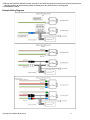
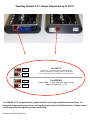
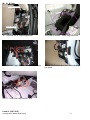
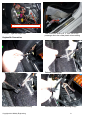
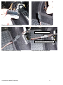
830 N Milwaukee Ave Chicago, IL 60642
312-421-1114
Smartkey Starter® Basic Installation Instructions
The Smartkey Starter® is designed as a direct plug in interface to the rear of the Mercedes Benz key cylinder. Please
read this manual in it’s entirety prior to installation as there is a specific order of operation that needs to be followed.
Tools and Parts you will need
-T-20 driver
-T-25 driver
-Philips screwdriver
-10mm socket and ratchet
-Drill
-3/4” drill bit or Unibit
-Panel removal tool
-Mercedes Benz EIS removal tool p/n 639 589 01 07 00 (optional in most installations, but can make the job much
easier. This can be purchased from your local Mercedes dealer. Alternatively, we can provide you one with your
order). Also, we include this tool in our Smartkey Starter® Combo package which allows you to stock all parts
required to accommodate any Mercedes that we support in one simple kit.
Vehicle Diagrams available at http://www.smartkeystarter.com/service.htm
!
DO NOT MOUNT THE MODULE NEAR ANY HEAT SOURCES IN THE
VEHICLE. SPECIFIC LOCATIONS TO AVOID ARE THE HEATER CORE AND
THE TRANSMISSION TUNNEL.
Basic Installation
Gain access to the rear of the key cylinder (EIS).
Remove the plug(s) from the rear of the EIS that correspond to the harness to be installed.
Plug the T harness male plugs into the rear of the EIS.
Plug in the factory wiring removed in step 2 to the opposite side of the T harness.
Plug the Smartkey Starter® module into the end of the T harness.
If the vehicle has KeylessGo see KeylessGo connection section below
Turn on the Valet Switch.
Start the vehicle with the key and allow it to run for 1 full minute to verify all connections are properly locked in place
and there are no errors or warning lights.
9. Shut the vehicle off and push the panic button once to start the vehicle. Remotes lacking a panic button should use
“lock-unlock-lock” to activate the remote start sequence (see activation programming section below).
10.External lights will flash once to confirm receipt of start command and vehicle will start.
11.External lights will flash once every 5 seconds while vehicle is running.
12.Key take over
a. Standard vehicle -- insert key into ignition and turn to on position. Lights will flash (3) times and control will
automatically be transferred to the key and remote start will turn off.
b. KeylessGo vehicle -- push start button (1) time. Lights will flash (3) times and control will automatically be
transferred to the key and remote start will turn off.
13.Once all is confirmed working, shut down the vehicle.
14.Route the Valet switch to a convenient location under the dash.
15.Drill a 3/4” hole for mounting the valet switch.
16.Disconnect the wires from the switch and snap the valet switch into place.
17.Reconnect the wires and confirm starter operation once again prior to reassembling the vehicle.
1.
2.
3.
4.
5.
6.
7.
8.
Copyright 2010 Midcity Engineering!
1
18.Mount the Smartkey Starter® module securely in the dash cavity away from any heat source (see previous
warning) and tie up all harnessing neatly and away from any heat source or moving parts.
19.Reassemble vehicle.
Example Wiring Diagrams
164/221
Copyright 2010 Midcity Engineering!
2
Smartkey Starter® V2.7 Jumper Adjustment up to V27.5*
Right
For SKS-FT:
Left
Jumper Right -- 2010-2011 ML, GL, R Bluetec Diesel
Jumper Left (pictured) -- 2006-2011 ML, GL, R Gasoline,
03-07 C, 04-09 E, CLS, CLK, 2005-2011 G, SLK 2004-2010
Right
For SKS-HS:
Left
Jumper Right -- C, GLK, 2010-up E (gas or diesel)
Jumper Left (pictured) -- S, CL
* for SKS-HS v27.6, all applications, jumper should be to the right position as shown above. If a
KeylessGo programming error arises, moving the jumper to the left will fix the issue. Please contact
us with any questions regarding jumper positioning.
Copyright 2010 Midcity Engineering!
3
2010-up E Class Sedan (W212) and 2012 CLS (W218) power wire connection
The SKS204 harness covers the 2008-2010 C, 2010 GLK, 2010-up E class coupe and sedan, and 2012 CLS
vehicles. Everything is identical in the connections between the aforementioned vehicles except for the 2010-up E
class sedan and 2012 CLS. There is no power wire in the harness that you will be interfacing with, thus the Smartkey
Starter® doesn’t have a power source. In this case, you will have to cut one wire from the harness and route a power
wire from the battery under the hood to the valet switch of the Smartkey Starter®. Please see the following diagram
for the correct connection point.
Bottom row, third pin from the left
1.
2.
3.
Cut the above wire and insulate the exposed end coming from the plug.
Remove the other end of that wire which is connected to the valet switch.
Route included wire from battery to empty terminal of switch and connect the spade to the empty switch
terminal.
Activation programming
Most Mercedes in the US and Canada have a panic button on the keyfob. Most Mercedes elsewhere in the world do
not have a panic button. The option is offered for 2 types of factory keyfob activation, panic button or “lock-unlocklock” for those vehicles not equipped with the panic feature.
If the vehicle is equipped with a Push start button on the dash, grasp the button and pull it out of the ignition switch.
Insert the key in the ignition switch and cycle it (5) five times from off to accessory (only one click in the clockwise
direction) and back to off.
The lights will flash once.
Pushing lock at this time turns the “lock-unlock-lock” sequence on.
Pushing unlock at this time turns the “lock-unlock-lock” sequence off.
Copyright 2010 Midcity Engineering!
4
KeylessGo Connection (not required for 2004-2009 E, 2004-2011 CLS, 2004-2009 CLK)
Tools and Parts Required
T-20 Driver
Pick Tool
Panel Removal Tool
Digital Multimter/Voltmeter
10KΩ Resistor
Description
In order to activate KeylessGo vehicle entry during remote start, an extra harness will have to be run to a separate
CAN connector in the vehicle. The aforementioned harness will be plugged into the 2 pin port next to the main
connector on the Smartkey Starter® module. These instructions assume the Smartkey Starter® has already been
installed in the vehicle and is working properly.
Instructions
1. Locate the CAN distribution block that houses the KeylessGo connector. (see location chart below)
2. Remove all connectors from the block that contain brown and brown/red twisted wires.
3. Locate the KeylessGo module (see location chart below)
4. Unplug the KeylessGo module.
5. Unclip and remove the connector cover from the KeylessGo connector.
6. Locate the twisted brown and brown/red wires in the plug.
7. Insert a 10kΩ resistor between the brown and brown/red wires in the connector.
8. Using your meter, measure the resistance between the two wires on each plug at the CAN block that were removed
in step 2 until you find the plug that reads 10kΩ across the two wires.
9. Plug all the other connectors back into the CAN block except for the KeylessGo connector that you located in step 8
10.Using a pick tool or small flat blade, open the retaining clip that holds the connecting terminals on the side of the
connector housing.
11.Using a pick tool or small flat blade release the tabs on each pin and remove them from the connector housing.
There are 2 separate times the release tab will need to be pressed down to remove it from the connector housing.
12.Close the retaining clip and put the empty connector housing back into the CAN block.
13.Insert the pins into the provided plug housing making sure the polarity is correct with the extension harness coming
from the Smartkey Starter®. Brown/red--->Brown/red and Brown--->Brown
14.Close the retaining clip on the new connector.
15.Plug the connector in to the harness from the Smartkey Starter®.
Location chart
Vehicle
2006-2011 GL
2006-2011 ML*
2006-2010 R*
2011 R*
2007-2010 S, CL
2011 S, CL
2010-11 E cpe/sdn
2012 CLS
2010-11 E convert.
2008-2011 C
2010-2011 GLK
2011 E Wagon
CAN Block
Right side compartment in cargo area
Passenger front kick panel*
Passenger front kick panel*
Passenger front kick panel*
Under rear of driver’s front seat
Under rear of driver’s front seat
Passenger front door jamb in wire trough
Passenger front door jamb in wire trough
Passenger front door jamb in wire trough
Passenger front door jamb in wire trough
Passenger front door jamb in wire trough
Passenger front door jamb in wire trough
KeylessGo Module
Right side compartment in cargo area
Right side compartment in cargo area*
Below spare tire in cargo*
Under false floor behind driver’s seat*
Right side of trunk near tail light
Left side of trunk behind metal bracket
Right side of trunk near tail light
Right side of trunk near tail light
In trunk behind rear seat back (remove carpet trim)
Right side of trunk near tail light
Center of cargo floor under carpet
Right side of cargo area behind bracket
*ML and R class do not require to change connector plug (steps 10-14 not required). They just need to be plugged in
to the extension harness once the correct connector is found in the block.
KeylessGo Component Locations
Copyright 2010 Midcity Engineering!
5
ML, GL, R Class
KeylessGo Module
CAN connector
GL -- right rear side of cargo compartment
R KeylessGo module -- under cargo area floor
ML KeylessGo -- right rear side of cargo compartment
ML and R CAN distribution block, front passenger
kick panel
2011 R -- under floor behind driver’s seat
S and CL (2007-2010)
Copyright 2010 Midcity Engineering!
6
CAN connector
Keylessgo Module
Right rear corner of trunk
Under rear of driver’s seat
S and CL (2011)
C, E, and GLK
KeylessGo Module
Left side trunk, remove metal bracket
GLK under cargo floor behind seat
KeylessGo Module
KeylessGo
plug on module
in trunk
Plug removed - faces body of car
E coupe KeylessGo module -- right rear of trunk
Copyright 2010 Midcity Engineering!
C and E Sedan KeylessGo module -- right rear trunk
7
KeylessGo module behind bracket
E Wagon -- right rear cargo area
CAN connector, 2010-up E, C, GLK, 2012 CLS
passenger front door under plastic wire moulding
KeylessGo Connection
CAN plug removed! !
!
!
!
!
Release retaining clip
!
Pins removed, connector housing empty
!
Remove pins from connector housing!
Copyright 2010 Midcity Engineering!
!
8
!
Empty connector housing reinstalled!
!
!
Pins ready for new connector housing
Brown matches to brown
Brown/red matches to brown/red
Pins installed in connector housing!
Copyright 2010 Midcity Engineering!
!
!
Plugs matched up and completed
9
SKS On Board KeylessGo Finder Instructions (sks v27.4 and up)
Beginning with V27.4 (see serial number sticker on the rear of the SKS unit), there is an on board KeylessGo finder. This will
make finding the correct plug for connecting to the KeylessGo system on vehicles that require it much easier. The basic install of
the Smartkey Starter® needs to be completed prior to testing for KeylessGo (this guide assumes the starter module is installed
and properly working).
Instructions
1. Locate the specified CAN distribution block where the KeylessGo connection should be made.
2. Turn the key to accessory (one click clockwise from the off position). If there is a push button in the ignition cylinder, it can be
removed so the key can be inserted in its place. Grasp the button and pull it out of the ignition switch.
3. Look inside the Smartkey Starter® module through the end plate opposite the main wiring plug. You should see red LEDs that
are lit up. One of those should be flashing at a slow pace.
4. In the CAN distribution block, begin to remove connectors one at a time. Each connector should be unplugged for 15-20
seconds each. Observe the flashing light as you do this. You should end up with two connectors that cause the flashing light to
stop flashing and stay solid on or solid off.
5. Isolate those two connectors to one end of the distribution block and leave the rest alone.
6. Turn the key to the off position and remove it.
7. Take the two connectors from step 5 and remove one at a time. Once one is removed, use the keyfob to unlock the doors.
Removing one of those connectors will cause the door locks to stop working from the keyfob and one won’t.
8. Take the connector that caused the door locks to stop working and plug it back in.
9. Connect the KeylessGo harness to the plug from step 7 where the door locks continued to work.
DEI Connection Instructions
Each DEI compatible Smartkey Starter® is equipped with a (4) pin and a (3) pin connector at the end.
The (4) pin connector is designed to accept a D2D cable from an XL202 RF translator module to provide the ability for
adding long range remotes and 2 way capability to the Smartkey Starter®. There is no programming required for the
module. The remotes need to be programmed to the XL202 which should have instructions provided with it.
The (3) pin connector is designed to accept the ESP cable that comes with the Directed SmartStart module (DSM100
or DSM200). The cable can be plugged directly in to the port. The power and ground must be connected (soldered
and taped) to the Smartkey Starter® harness. Please see the below diagram.
SmartStart power
top row, first pin,
red
SmartStart ground
bottom row, first
pin, brown
Copyright 2010 Midcity Engineering!
10
Compustar Programming Instructions
To program any compatible Compustar remote control, complete the above installation steps and verify standard
operation.
If the vehicle is equipped with a Push start button on the dash (push buttons in the gear selector lever do not come out
in this manner, nor are they applicable in this case), grasp the button and pull it out of the ignition switch.
Insert the key in the ignition switch and cycle it (5) five times from off to accessory (only one click in the clockwise
direction) and back to off.
The lights will flash once. Press lock or button 1 on the remote control and the lights will flash to confirm
programming. Up to (4) Compustar remotes can be programmed to one unit.
Once all remotes have been programmed, wait for a single light flash confirmation signifying the module has exited
programming mode.
Verify the operation of the new remote.
Insert KeylessGo button back into ignition (if applicable) when finished.
Compustar Drone DR-1000 Connection
!
DO NOT USE BLUE PORT FOR DRONE CONNECTION.
DRONE DATA CABLE MUST PLUG INTO BLACK PORT MARKED RS232.
Drone power
top row, first pin,
red
Drone ground
bottom row, first
pin, brown
Copyright 2010 Midcity Engineering!
11
Troubleshooting Diagnostic Flashes
While running on remote start, any of the following will cause vehicle shut down
−
−
−
−
−
opening the hood
(7 flashes)
depressing the brake pedal (6 flashes)
increasing the RPM over normal idle (8 flashes)
three failed starts/low RPM (9 flashes)
communications error (10 flashes)
The vehicle will be limited to (5) remote starts between normal keyed operation.
If the lights flash (5) times the starter is out of sync with the vehicle. This is a rare occurrence. Should it happen, you
must start the vehicle with the key or the KeylessGo button for at least one minute to synchronize.
Copyright 2010 Midcity Engineering!
12