1
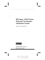
. . . . . . . . . . . . . . . . . . . . . . . . DEClaser 3500 Printer External Fax Modem Installation Guide Order Number: EK-D350P-EI.A01 d Digital Equipment Corporation Maynard, Massachusetts 190287-001 - 06/01/95 - - Saved by IDC - Rev # - File Name EXFX_US6.DOC . . . . . . . . . . . . . . . . . . . . . . . . First Printing, December 1994 Digital Equipment Corporation makes no representations that the use of its products in the manner described in this publication will not infringe on existing or future patent rights, nor do the descriptions contained in this publication imply the granting of licenses to make, use, or sell equipment or software in accordance with the description. Possession, use, or copying of the software described in this publication is authorized only pursuant to a valid written license from Digital or an authorized sublicensor. Digital Equipment Corporation 1994. All Rights Reserved. Printed in the U.S.A. The following are trademarks of Digital Equipment Corporation: DECimage Plus, DEClaser, DECnet, DECprint, DECserver, DECstation, LATprint, OpenDECconnect, OpenVMS, PrintServer, ULTRIX, VAX, VAXstation, Digital, and the DIGITAL logo. All other trademarks and registered trademarks are the property of their respective holders. 2 190287-001 - 06/01/95 - - Saved by IDC - Rev # 2 - File Name EXFX_US6.DOC . . . . . . . . . . . . . . . . . . . . . . . . Approval Information for Australia Failure to set the modem, and any communications software used with the modem, to the values contained in the following table, will result in the modem being operated in a noncompliant manner. Consequently, there would be no permit in force for this equipment and the Telecommunications Act 1991 prescribes a penalty of $12 000 for the connection of nonpermitted equipment. S-Register Function S0 S6 S7 S10 Number of rings to answer Blind dial wait time Wait for carrier time Loss of carrier disc. Default Permitte d Range Units 2 4 55 14 1 to 4 2 to 4 4 to 55 0 to 30 Rings Seconds Seconds Seconds PTT Approval Information For Holland The DEClaserFAX is made in England and is approved in Holland for connection to the general switched telephone network, either directly or through an approved PABX. Users with modem line connections to some types of PABX or switched network exchanges must be aware that such equipment may take between 5 and 40 seconds to return a dial tone after the DEClaserFAX seizes the line. Due to PTT approval or other statutory requirements, the following differences exist in the operation of the DEClaserFAX when configured for use in Holland and the standard UK configuration: • Blind dialling Dialling in the absence of a dial tone is not permitted. Therefore, the X options that cause the DEClaserFAX to ignore the dial tone, X0 and X3, are disabled. • Comma pause Register S8 is not applicable and any comma included in a dial string is ignored. Therefore, the "," option (the comma character) that inserts a pause during dialling is not permitted. 3 190287-001 - 06/01/95 - - Saved by IDC - Rev # 2 - File Name EXFX_US6.DOC . . . . . . . . . . . . . . . . . . . . . . . . • Repeat dialling and blacklisting After a failed dial attempt, the DEClaserFAX prevents a second dial attempt to that number for 5 seconds. Subsequent attempts are not allowed for 1 minute. Any attempt to dial a particular number more than 15 times in 1 hour causes the number to be blacklisted. No dial attempts are allowed to a blacklisted number until the DEClaserFAX has been switched off and on again. • Call clear down If no tones are detected within 20 seconds of a call attempt, the DEClaserFAX terminates the call attempt, goes back onhook, and returns to command mode. • Congested tone If the DEClaserFAX detects a congested tone for a continuous period of 20 seconds, the DEClaserFAX terminates the call attempt, goes back on-hook, and returns to command mode. BABT Approval Information The Digital Equipment Corporation DEClaserFAX is made in England and is approved by BABT for connection to telecommunications systems specified in the instructions for use and subject to the conditions set out in them. The information provided in this section relates to the statutory requirements under which the approval was granted. The approval number is NS/1232/23/R/605063 All apparatus connected to the DEClaserFAX and thereby connected directly or indirectly to the BT PSTN circuits must be approved apparatus as defined in Section 22 or 16 respectively, of the British Telecommunications Act 1984. Applicable circuits: This apparatus is approved for connection to the Public Switched Telephone Network provided by British Telecommunications Plc, Kingston-upon-Hull City Council, and Mercury Communications Ltd. It is suitable for household, office and similar general indoor use when connected to single exclusive exchange lines employing either Pulse (Loop Disconnect) or Tone (DTMF) dial signalling and terminated with a BT type 600 series modular socket. It is not suitable for shared services. 4 190287-001 - 06/01/95 - - Saved by IDC - Rev # 2 - File Name EXFX_US6.DOC . . . . . . . . . . . . . . . . . . . . . . . . For statutory purposes, apparatus connected to the PSTN through a Relevant Branch System (RBS) is treated as if connected directly to the PSTN. The definition of an RBS is given in document BS6789 Section 6.1 clause 2.4. Ringer equivalence number (REN): All equipment approved for connection to the Public Switched Telephone Network is assessed to determine its REN. This value indicates the degree of load placed on the line by the apparatus and therefore determines how the device affects the ringing characteristics of other equipment attached in parallel. The maximum permitted REN value for a single exchange line is 4. If the sum of the REN values for attached equipment exceeds this value, the ringer capacity of the line may be exceeded and the attached equipment may cease to operate correctly. The REN value of a standard BT telephone is 1 unless otherwise marked. The REN value of this apparatus is 1. Because of the wide spread of ringing detector characteristics, a guarantee of successful operation in an installation of mixed types of ringing detectors can not be given by the supplier. Approved functions: This apparatus has been approved for the use of the following facilities: Storage of numbers for retrieval by a pre-determined code Automatic call initiation Detection of Initial Proceed Indication Detection of Secondary Proceed Indication Operation in the absence of Proceed Indication Automatic Multi-frequency tone (DTMF) or Pulse (Loop disconnect) dialing Automatic storage of last number dialled Tone detection for Ring, Busy, Equipment Engaged, Number Unobtainable Manual repeat dialling of last number Auto clear from call originating end Automatic answering Loudspeaker Modem operation using the standards: V21, V23, V22, V22bis, V27ter, and V29 Any other use invalidates the approval of the apparatus if, as a result, it ceases to conform to the standards against which the approval was granted. 5 190287-001 - 06/01/95 - - Saved by IDC - Rev # 2 - File Name EXFX_US6.DOC . . . . . . . . . . . . . . . . . . . . . . . . Connection to the telephone system: If the telephone line does not have a wall socket compatible with a type 431A plug, arrange for the installation of an appropriate socket and/or extension as follows: • If the extension wiring is owned by British Telecom, contact the local British Telecom sales office to request installation of the correct socket, using the post card provided. Fill out the post card including the address listed for British Telecom in your local telephone directory. • If the extension wiring is not owned by British Telecom, the authorised maintainer of the PBX must install the correct extension and/or socket. Another person can perform the installation if the authorised maintainer has been given 14 days written notice and that period of notice has expired. If you intend to share a single exchange line for nonsimultaneous voice and data/fax use, use a suitable approved "T-splitter". Fit this at the wall socket before connecting the DEClaserFAX and/or telephone. Auto-calling: To minimise the risk of inconvenience to other network subscribers, check carefully all numbers entered during the Auto Call set-up stage prior to dialling and when storing numbers in the non-volatile store. Auto-answering: This apparatus may be configured for either manual or automatic answering modes. Automatic answering mode is enabled by setting register S0 to a value greater than 0. The value is the number of rings before DEClaserFAX answers. Connection to PBXs: This apparatus is approved for use as an extension instrument to compatible PBXs. Please contact the supplier for an up-to-date list of compatible PBXs. It cannot be guaranteed that the apparatus operates correctly under all possible conditions of connection to compatible PBXs. Report any difficulty to the supplier. This apparatus is suitable for connection to PBXs which return a Secondary Proceed Indication. It is not suitable for use with Key systems. 6 190287-001 - 06/01/95 - - Saved by IDC - Rev # 2 - File Name EXFX_US6.DOC . . . . . . . . . . . . . . . . . . . . . . . . Safety Statement Before proceeding with the installation, you should read the following statement and the national appendix containing statutory information for the country in which you will be using the DEClaserFAX. The DEClaserFAX meets the requirements of European safety standards EN60950 : 1992 (BS7002 : 1992) and EN41003 : 1993. In compliance with these standards, the safety status of the ports intended for the interconnection of other equipment is as follows: Port Status 25-pin, D RS232 socket Safety Extra Low Voltage (SELV) PSTN socket Telecommunication Network Voltage (TNV) These connectors must only be used to connect the DEClaserFAX to other ports or circuits having the same safety status. BZT Hinweis DEClaserFAX wurde gemäß den Bestimmungen von EN55022 und VDE0878 Tiel 1 Klasse B mit Bezug auf Störspannungen und elektromagnetische Störstrahlungen getestet. Seine Kompatibilität mit dem mitgelieferten DTE-Kabel wird hiermit bescheinigt. Dem Bundesamt für Zulassungen in der Telekommunikation wurde das Inverkehrbringen dieses Gerätes angezeigt und die Berechtigung zur Überprüfung der Serie auf die Einhaltung der Bestimmungen eingeräumt. 7 190287-001 - 06/01/95 - - Saved by IDC - Rev # 2 - File Name EXFX_US6.DOC . . . . . . . . . . . . . . . . . . . . . . . . Electrostatic Discharge A discharge of static electricity from a finger or other conductor may damage circuit boards or other static-sensitive devices. This type of damage may reduce the life expectancy of the device. To prevent electrostatic damage, observe the following precautions: n Avoid hand contact by transporting and storing parts in static-safe containers. n Keep electrostatic-sensitive parts in their containers until they arrive at static-free work stations. n Place parts on a grounded surface before removing them from their container. n Avoid touching pins, leads, or circuitry. n Always be properly grounded when touching a staticsensitive component or assembly. Grounding Methods Use one or more of the following grounding methods when handling or installing electrostatic-sensitive parts: n Use a flexible wrist strap with a minimum of 1 megohm ± 10 percent resistance in the ground cord that is connected to a grounded workstation or the printer chassis. To provide a proper ground, wear the strap snug against the skin. n Use heel straps, toe straps, or boot straps on both feet at standing workstations. Stand on conductive floors or dissipating floor mats. n Use conductive field service tools. n Use a portable field service kit with a folding staticdissipating work mat. If you do not have the proper grounding equipment, have an Authorized Service Provider install the part. NOTE: For additional information on static electricity, or assistance with the installation of this product, contact your Authorized Service Provider. 8 190287-001 - 06/01/95 - - Saved by IDC - Rev # 2 - File Name EXFX_US6.DOC . . . . . . . . . . . . . . . . . . . . . . . . INTRODUCTION The DEClaserFAX is an external modem for the DEClaser 3500 printer. The DEClaserFAX can send and receive Group III and PostScript faxes. Digital recommends 8MB of RAM for this option. DEClaserFAX Kit Contents n Serial interface board n DEClaserFAX modem n Telephone cable n Interface cable n Telephone socket adapter, where applicable n Software and its documentation n This guide Items Needed for Installation n This Kit n Non magnetic Phillips screwdriver 9 190287-001 - 06/01/95 - - Saved by IDC - Rev # 2 - File Name EXFX_US6.DOC . . . . . . . . . . . . . . . . . . . . . . . . INSTALLATION STEP 1 TURN THE PRINTER OFF (O) AND UNPLUG THE POWER CORD. STEP 2 DISCONNECT ALL CABLES FROM THE PRINTER. 10 190287-001 - 06/01/95 - - Saved by IDC - Rev # 2 - File Name EXFX_US6.DOC . . . . . . . . . . . . . . . . . . . . . . . . ! WARNING: Turn the printer off and unplug the AC power cord before attempting to remove the system controller board. Failure to do so may result in an electrical shock or damage to the printer. WARNUNG: Schalten Sie den Drucker aus und ziehen Sie den Stecker des Netzteil-Adapters, bevor Sie die Systemsteuerungskarte ausbauen. Andernfalls besteht die Gefahr elektrischer Schläge oder einer Beschädigung des Druckers. AVERTISSEMENT: Mettez l'imprimante hors tension et débranchez le cordon d'alimentation secteur avant d'enlever la carte contrôleur. Toute omission de votre part risquerait de provoquer une décharge électrique ou d'endommager l'imprimante. AVVERTENZA: Spegnere la stampante e staccare il cavo di alimentazione CA prima di rimuovere la scheda del controller del sistema al fine di evitare scosse elettriche o danni alla stampante. ADVERTENCIA: Apague la impresora y desenchufe el cable de alimentación de CA antes de extraer la tarjeta controladora del sistema o, del lo contrario, se puede producir una descarga electrostática o se puede estropear la impresora. WAARSCHUWING: Schakel de printer uit en neem de stekker uit het stopcontact voordat u de systeemcontrollerkaart verwijdert. Als u dit niet doet, kunt u een elektrische schok krijgen of de printer beschadigen. CAUTION: To avoid electrostatic damage to the printer option and/or system controller board, follow the safety precautions outlined in "Electrostatic Discharge." 11 190287-001 - 06/01/95 - - Saved by IDC - Rev # 2 - File Name EXFX_US6.DOC . . . . . . . . . . . . . . . . . . . . . . . . STEP 3 PRESS DOWN ON THE TABS TO OPEN AND LOWER THE REAR COVER. STEP 4 1 2 3 LOOSEN THE THUMBSCREWS AND REMOVE THE SYSTEM CONTROLLER BOARD. 1 Thumbscrews 2 System Controller Board 3 Rear Cover 12 190287-001 - 06/01/95 - - Saved by IDC - Rev # 2 - File Name EXFX_US6.DOC . . . . . . . . . . . . . . . . . . . . . . . . STEP 5 2 1 2 3 REMOVE A BLANK PLATE COVERING EITHER INTERFACE CONNECTOR SLOT. 1 Blank Plate 2 Mounting Posts (not used) 3 Retaining Bracket 13 190287-001 - 06/01/95 - - Saved by IDC - Rev # 2 - File Name EXFX_US6.DOC . . . . . . . . . . . . . . . . . . . . . . . . STEP 6 J7 J9 A. VERIFY THE CORRECT PLACEMENT OF JUMPERS ON THE SERIAL BOARD: P1 HAS A JUMPER. P2 DOES NOT HAVE A JUMPER. B. PLUG THE SERIAL BOARD CONNECTOR INTO LOCATION J7 OR J9 AND SECURE. 14 190287-001 - 06/01/95 - - Saved by IDC - Rev # 2 - File Name EXFX_US6.DOC . . . . . . . . . . . . . . . . . . . . . . . . STEP 7 1 2 3 REINSTALL AND SECURE THE CONTROLLER BOARD AND CLOSE THE REAR COVER. 1 Thumbscrews 2 System Controller Board 3 Rear Cover 15 190287-001 - 06/01/95 - - Saved by IDC - Rev # 2 - File Name EXFX_US6.DOC . . . . . . . . . . . . . . . . . . . . . . . . STEP 8 RECONNECT ALL CABLES BUT DO NOT APPLY POWER. 16 190287-001 - 06/01/95 - - Saved by IDC - Rev # 2 - File Name EXFX_US6.DOC . . . . . . . . . . . . . . . . . . . . . . . . STEP 9 ATTACH ONE END OF THE INTERFACE CABLE TO THE SERIAL BOARD AND ATTACH THE OTHER END TO THE DECLASERFAX'S SERIAL PORT. The large 25-way D-shaped connector is the serial port. 17 190287-001 - 06/01/95 - - Saved by IDC - Rev # 2 - File Name EXFX_US6.DOC . . . . . . . . . . . . . . . . . . . . . . . . STEP 10 C B A 18 190287-001 - 06/01/95 - - Saved by IDC - Rev # 2 - File Name EXFX_US6.DOC . . . . . . . . . . . . . . . . . . . . . . . . A. PLUG THE TELEPHONE CABLE INTO THE DECLASERFAX'S PSTN PORT. The telephone cable connects the DEClaserFAX to the public telephone network. One end of the lead has a clear RJ11-style plug. The other end has a plug for connection to the wall socket, either directly or using an adapter. Plug the RJ11-style plug into the PSTN port of the modem, the square 6-pin socket. B. IF USING AN ADAPTER, PLUG THE OTHER END OF THE CABLE INTO THE ADAPTER. C. PLUG THE ADAPTER OR TELEPHONE CABLE INTO THE WALL SOCKET. ! WARNING: Be sure to plug the telephone cable into the modem before you connect the modem to the telephone system. Once the cable has been connected, it cannot be removed without the use of a small screwdriver. This is deliberate and is intended to prevent accidental shock from Telecommunications Network Voltages (TNV). 19 190287-001 - 06/01/95 - - Saved by IDC - Rev # 2 - File Name EXFX_US6.DOC . . . . . . . . . . . . . . . . . . . . . . . . STEP 11 PLUG IN THE PRINTER AND TURN IT ON (I). The DEClaserFAX requires a nominal 9-V DC supply at 132 mA. This power is supplied by the printer through the 25-way serial port connector. The DEClaserFAX has a power supply port, the round 3.5-mm jack socket on the side of the DEClaserFAX, but this is not required for operation with your printer and no connection should be made to this socket. 20 190287-001 - 06/01/95 - - Saved by IDC - Rev # 2 - File Name EXFX_US6.DOC . . . . . . . . . . . . . . . . . . . . . . . . CAUTION: DO NOT push the yellow Reset button on the DEClaserFAX. If you push the button, turn the printer off (O) then on (I) to clear the reset. 21 190287-001 - 06/01/95 - - Saved by IDC - Rev # 2 - File Name EXFX_US6.DOC . . . . . . . . . . . . . . . . . . . . . . . . STEP 12 TEST THE HARDWARE INSTALLATION. 1. Using the printer's control panel, press the Menu key. The printer is off-line and in menu mode. 2. Press the Item button to display the Reports item. Press Select. Press the Item button to display the Hardware Report item. Press Select. The printer prints the Hardware Report. If the report includes an entry for "FAX Modem", the serial board interface is working correctly. 3. Press the Item button to display the Fax Report item. Press Select. The printer prints the Fax Report. This report proves that the modem-to-printer connection is working. 4. Press On-line ( On-line, En ligne, In linea, En línea) to end the menu mode. If the FAX Modem is not listed on the Hardware Report: 1. Make sure that all cables are in good working order and connected securely. 2. Make sure that the board is properly connected and fully seated in the J7 or J9 slot. 3. Check that the jumper on the serial board is placed correctly. The P1 jumper enables power so the jumper must be inserted. The P2 jumper controls the operation of the board; the jumper must be removed to enable fax operations. 4. Reprint the Hardware Report. 5. If the modem is still not listed, contact your Authorised Service Provider. If the FAX Modem is listed on the Hardware Report but you cannot print a Fax Report or it consists of a PostScript error: 1. Make sure the cable to the modem's serial port is in good working order and connected securely. 22 190287-001 - 06/01/95 - - Saved by IDC - Rev # 2 - File Name EXFX_US6.DOC . . . . . . . . . . . . . . . . . . . . . . . . 2. Check that the P1 jumper on the serial board is placed correctly. The P1 jumper enables power so the jumper must be inserted. 3. Reprint the Fax Report. 4. If the report still does not print, contact your Authorised Service Provider. AFTER INSTALLATION The DEClaserFAX kit contains software to allow your operating system to use the DEClaserFAX. See the documentation for installation instructions. Set the clock using either the Fax menu on the printer's control panel or the software that ships with the DEClaserFAX. See the printer User's Guide for instructions on using the control panel. TROUBLESHOOTING When the printer and the fax modem are working properly, the green LED (power supply) is always on. It turns on 15 seconds after the printer is powered on. Check that the printer can receive faxes. The printer receives a fax through an external telephone line, so no software is needed. During transmission of a fax, the control panel displays the message "Receiving Fax. . ." and the red LED next to the power-supply LED flashes every second, then flashes rapidly at the end of the transmission. If you cannot receive a fax, perform the following steps: 1. Verify that the power-supply LED is on. If not, check the serial board and its P1 jumper. 2. Verify that the interface cable, from the serial interface to the modem, is connected properly. 3. Verify that the PSTN cable, the telephone line, is connected properly. 4. Verify the telephone line by disconnecting the printer from the modem and connecting another telephone to the modem. Then call the printer's telephone line from another location. 23 190287-001 - 06/01/95 - - Saved by IDC - Rev # 2 - File Name EXFX_US6.DOC . . . . . . . . . . . . . . . . . . . . . . . . Note: If the printer can receive faxes but can not send them, the problem is most likely to be with the fax utility software. Refer to the software's documentation and check the troubleshooting information. Check that the printer can send faxes. The printer sends a fax when an application issues a print command and the printer driver software defines the print output as fax output. When you send a fax, nothing appears to happen for about 30 seconds. After this delay, you can hear the dial tone from the telephone network. You can then hear the fax number being dialed. When the answering fax machine responds, the fax modem exchange information and then the transmission of your fax begins. The printer control panel displays "Sending Fax. . ." and the red LED flashes. At the end of the transmission, you hear a tone and the red LED flashes rapidly then stops. If the printer can not send a fax, perform the following steps: 1. Verify that the receiving fax is in working order. Dial the number of that fax machine and listen for the sequence of tones that indicate that a fax machine is ringing, answering, and beginning the connection process. 2. Check the Transmission Status Report. The printer prints this report after every fax it sends, regardless of success or failure. Check the status message for the following messages: No Dial Tone means the telephone line or wall circuit is not functioning. Callee Didn't Respond means the fax modem is not communicating with the printer. Check the serial interface cable and check the power supply LED. Turn the printer off and back on again. 24 190287-001 - 06/01/95 - - Saved by IDC - Rev # 2 - File Name EXFX_US6.DOC