1
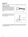
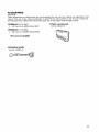
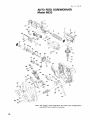
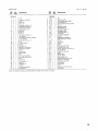
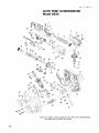
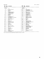
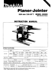
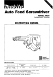
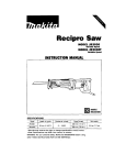
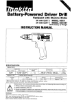
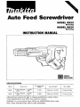
Screwdriver
MODEL 6833
Reversing
MODEL 6834
Reversing
INSTRUCTION MANUAL
DOUBLE
INSULATION
SPECIFICATIONS
Model
I
Screw strip
I
No
';kag$Feed
I
Overall length
I
Net weight
6833
4 mm x 25 mm - 41 mm
(5/32"x 1" - 1-5/8"1
4,700
364 mm (14-3/8"1
1.9k g (4.2Ibs)
6834
4 mm x 25 mm
57 mm
(5/32"x 1" - 2-114")
2,800
396 mm (1 5-5/8")
1.9kg (4.2Ibsl
~
* Manufacturer reserves the right to change specifications without notice.
Note: Specifications may differ from country to country.
WARNING: For your personal safety, READ and UNDERSTAND before using.
SAVE THESE INSTRUCTIONS FOR FUTURE REFERENCE.
GENERAL SAFETY RULES
(For All Tools)
WARNING! Read and understand all instructions. Failure
to follow all instructions listed below, may result in electric
shock, fire and/or serious personal injury.
SAVE THESE INSTRUCTIONS
READ ALL INSTRUCTIONS.
WORK AREA
1. Keep your work area clean and well lit. Cluttered benches and dark areas invite
accidents.
2. Do not operate power tools in explosive atmospheres, such as in the presence
of flammable liquids, gases, or dust. Power tools create sparks which may
ignite the dust or fumes.
3.Keep bystanders, children, and visitors away while operating a power tool.
Distractions can cause you t o lose control.
ELECTRICAL SAFETY
4. Double Insulated tools are equipped with a polarized plug (one blade is wider
than the other.) This plug will fit in a polarized outlet only one way. If the
plug does not fit fully in the outlet, reverse the plug. If it still does not fit,
contact a qualified electrician t o install a polarized outlet. Do not change
the plug in any way. Double insulation
eliminates the need for the three
wire grounded power cord and grounded power supply system.
5. Avoid body contact with grounded surfaces such as pipes, radiators, ranges
and refrigerators. There is an increased risk of electric shock if your body is
grounded.
6. Don't expose power tools t o rain or wet conditions. Water entering a power
tool will increase the risk of electric shock.
7. Do not abuse the cord. Never use the cord t o carry the tools or pull the plug
from an outlet. Keep cord away from heat, oil, sharp edges or moving parts.
Replace damaged cords immediately. Damaged cords increase the risk of
electric shock.
8. When operating a power tool outside, use an outdoor extension cord marked
"W-A' or "W." These cords are rated for outdoor use and reduce the risk
of electric shock.
PERSONAL SAFETY
9. Stay alert, watch what you are doing and use common sense when operating
a power tool. Do not use tool while tired or under the influence of drugs,
alcohol, or medication. A moment of inattention while operating power tools
may result in serious personal injury.
I O . Dress properly. Do not wear loose clothing or jewelry. Contain long hair. Keep
your hair, clothing, and gloves away from moving parts. Loose clothes, jewelry
or long hair can be caught in moving parts.
2
11. Avoid accidental starting. Be sure switch is off before plugging in. Carrying
tools with your finger on the switch or plugging in tools that have the switch
on invites accidents.
12. Remove adjusting keys or switches before turning the tool on. A wrench or
a key that is left attached to a rotating part of the tool may result in personal
injury.
13. Do not overreach. Keep proper footing and balance at all times. Proper footing
and balance enables better control of the tool in unexpected situations.
14. Use safety equipment. Always wear eye protection. Dust mask, non-skid
safety shoes, hard hat, or hearing protection must be used for appropriate
conditions.
TOOL USE AND CARE
15. Use clamps or other practical way t o secure and support the workpiece t o
a stable platform. Holding the work by hand or against your body is unstable
and may lead t o loss of control.
16. Do not force tool. Use the correct tool for your application. The correct tool
will do the job better and safer at the rate for which it is designed.
17. Do not use tool if switch does not turn it on or off. Any tool that cannot
be controlled with the switch is dangerous and must be repaired.
18. Disconnect the plug from the power source before making any adjustments,
changing accessories, or storing the tool. Such preventive safety measures
reduce the risk of starting the tool accidentally.
19. Store idle tools out of reach of children and other untrained persons. Tools
are dangerous in the hands of untrained users.
20. Maintain tools with care. Keep cutting tools sharp and clean. Properly
maintained tools, with sharp cutting edges are less likely to bind and are easier
to control.
21. Check for misalignment or binding of moving parts, breakage of parts, and
any other condition that may affect the tools operation. If damaged, have
the tool serviced before using. Many accidents are caused by poorly maintained tools.
22. Use only accessories that are recommended by the manufacturer for your
model. Accessories that may be suitable for one tool, may become hazardous
when used on another tool.
SERVICE
23. Tool service must be performed only by qualified repair personnel. Service
or maintenance performed by unqualified personnel could result in a risk of
injury.
24. When servicing a tool, use only identical replacement parts. Follow instructions in the Maintenance section of this manual. Use of unauthorized parts
or failure to follow Maintenance Instructions may create a risk of electric shock
or injury.
3
Specific Safety Rules
1. Hold tool by insulated gripping surfaces when performing an operation where
the cutting tools may contact hidden wiring or its own cord. Contact with
a "live" wire will make exposed metal parts of the tool "live" and shock the
operator.
2. Always be sure you have a firm footing.
Be sure no one is below when using the tool in high locations.
3. Hold the tool firmly.
4. Keep hands away from rotating parts.
5. Do not leave the tool running. Operate the tool only when hand-held.
6. Do not touch the drill bit or the workpiece immediately after operation; they
may be extremely hot and could burn your skin.
SAVE THESE INSTRUCTIONS.
4
SYMBOLS
The followings show the symbols used for tool.
A
....................
.................................
volts
.................................
herts
.................................
kilograms
.................................
hours
.................................
......................
minutes
.................................
alternating current
.................................
direct current
.................................
no load speed
.................................
alternating or direct current
.................................
Class I 1 Construction
............................
amperes
seconds
splash-proof construction
AA
.....................
.../ min
................................
revolutions or reciprocation per minute
E=
.................................
number of blow
.... watertight construction
5
Setting for desired screw length
There are 3 (for Model 6833) or 5 (for Model 6834) positive-lock screw length settings. To
obtain the desired setting, pull out the stopper base while depressing the lever until you
see the number of the desired screw length (indicated on the plate) appear to rest on the
very top edge of the casing. See the table below for the relation between the number indicated on the plate and the respective screw length ranges.
on the plate
25/28
Lever
32
40
51
57
I 25 - 28 (1
"
- 1-1/8")
I 2 8 - 3 5 (1-1/8" - 1/3/8")
I 35 - 4 1 (1-3/8" - 1-5/8")
1 41 - 51 (1-5/8" - 2")
I 51 57 (2" - 2-1/4")
-
(Notel * for Model 6834 onlv
Adjusting the driving depth
Depress the stopper plate as far as it will
go. While keeping it in this position, turn
the adjusting knob until the bit tip projects approx. 5 mm (3/16") from the stopper base. Drive a trial screw. If the screw
head projects above the surface of the
workpiece, turn the adjusting knob in the
A) direction; if the screw head is countersunk, turn the adjusting knob in the B
direction.
Installing the screw strip
Insert the screw strip through the screw guide. Then insert it through the feeder box until
the first screw reaches the position next to the driving position
A
strip
guide
I
6
I
Driving position
Removing the screw strip
To remove the screw strip, just pull it out in the direction of the arrow. If you depress the
reverse button, you can pull out the screw strip in the reverse direction of the arrow.
Carry hook
The carry hook is convenient for hooking
the tool to your belt. It can be installed on
either side of the tool. To remove it, pull it
out in the direction of the arrow while raising. To install the hook, push it down until it
"clicks" into place on the tool.
Switch action
CAUTl ON:
Before plugging in the tool, always check to see that the switch trigger actuates properly
and returns to the "OFF" position when released.
To start the tool, simply pull the trigger.
Release the trigger to stop. For continuous
operation, pull the trigger and then push in
the lock button. To stop the tool from the
locked position, pull the trigger fully, then
release it.
7'
Reversing switch action
This tool has a reversing switch to change
the direction of rotation. Press the upper
side (FWD side) of the switch for clockwise
rotation or the lower side (REV side) of the
switch for counterclockwise rotation.
switch
CAUTION:
Always check the direction of rotation before operation
*Use the reversing switch only after the tool comes to a complete stop. Changing the
direction of rotation before the tool stops may damage the tool.
Driving operation
Switch on the tool by pressing the trigger
and at the same time pushing the lock button. Hold the tool squarely against the
workpiece and apply forward pressure to
the tool. The screw will be automatically
carried to the driving position and driven
into the workpiece.
IMPORTANT:
Do not fire the tool without screws. This will damage the workpiece.
If the feeder box becomes sluggish in operation, spray car wax (spray type wax) on its
sliding surfaces. Never lubricate it.
8
Installing or removing the bit
CAUTION:
Always be sure that the tool is switched off and unplugged before installing or removing
the bit.
Loosen the thumb screw which secures the casing. Pull out the casing in the direction of
the arrow. Press the dust cover toward the plane bearing and pull out the bit. If the dust
cover cannot be moved as far as the plane bearing, try it again after turning the bit slightly.
To install the bit, insert it into the socket while turning it slightly. After installing, always
make sure that the bit is securely held in place by trying to pull it out.
,-
Casing
Plane bearing
Dust cover
I
0
Bit
Extension handle (optional accessory)
Use of extension handle allows you to drive
screws into floors while standing.
9
MAINTENANCE
CAUTION:
Always be sure that the tool is switched off and unplugged before attempting to perform
inspection or maintenance.
Replacing carbon brushes
Remove and check the carbon brushes
regularly. Replace when they wear down to
the limit mark. Keep the carbon brushes
clean and free to slip in the holders. Both
carbon brushes should be replaced at the
same time. Use only identical carbon
brushes.
Use a screwdriver to remove the brush
holder caps. Take out the worn carbon
brushes, insert the new ones and secure
the brush holder caps.
To maintain product SAFETY and RELIABILITY, repairs, any other maintenance or adjustment should be performed by Makita Authorized or Factory Service Centers, always using
Makita replacement parts.
10
ACCESSORIES
CAUTION:
These accessories or attachments are recommended for use with your Makita tool specified in this
manual. The use of any other accessories or attachments might present a risk of injury to persons.
The accessories or attachments should be used only in the proper and intended manner.
-
Phillips bit (5 per pkg.)
2 - 132 Part No. A-16536 (Model 68331
Plastic carrying case
Part No.824421-0
Phillips bit (1 per pkg.)
2 - 146 Part No. 784238-2 (Model 6834)
Extension handle
Part No. 192501-3
11
Msr.-11-'99
US
AUTO FEED SCREWDRIVER
Model 6833
Note: The switch, noise suppressor and other part configurations
may differ from country to country.
12
Mar-l1--'99
MODEL 6 8 3 3
ITEM
NO.
NO.
USED
OESCRIPTION
9
1
1
1
1
1
1
1
2
1
10
1
11
12
13
14
15
16
17
18
19
20
21
22
23
24
1
1
1
1
1
1
6
7
8
25
26
27
28
29
30
31
32
33
34
35
36
31
I
1
1
1
1
1
1
1
1
1
1
1
1
1
1
1
1
1
1
1
1
-
,& DESCRlfTlON
MACHINE
MACHINE
-~
1
2
3
4
5
'LiM
US
Level
Compression Spring 2
Pin 6
Feeder Box
Sleeve 5
Compression Spring 21
Casing Set IWit Item 171
Tapping Screw 4x20
Tapping Screw 4x12
Shifter Pin
Sleeve 8
Knob 42
Camecession Spring 1 2
Flat Washer 6
Countersunk Head Screw M4x12
Screw M4x28
Casing Set IWiI Item 71
Pl" 3
Torslo" sprmg 4
Stopper
Spur Gear 16
Ratchet Arm Complete
Compression Spring 6
Wheel
Dust Cover
Stopper Base
cap
Box Cover Complete
Pan Head Screw M4x16
Plate
Dust Cover
Plane Bearing 1 4
Ring 1 5
Steel Ball 3 5
Soindle
Compression S p m g 5
Flat Washer 6
38
39
40
41
42
43
44
45
46
47
48
49
50
51
52
54
55
56
57
58
59
60
61
62
63
64
65
66
67
68
69
70
71
72
73
74
-
1
1
1
1
1
3
1
1
1
1
1
1
1
1
1
1
1
I
1
1
2
1
1
10
1
1
2
2
1
1
2
1
1
1
1
1
-
P,"
Helical Gear 5 5
Thrust Needle Bearing 821
Plane Besrlng 8
Screw Guide Set (Wit Item 601
P," 4
Ball Bearing 606
Helical Gear 1 4
Spiral Bevel Gear 22
Ball Bearins 606
Spiral Bevel Gear 15
0 Ring 22 4
Ball Bearing 6OOOLLB
Fan 55
ARMATURE ASSEMBLY
IWilh Item 50, 51 & 581
Switch
Dust Cover
Switch
Field
Ball Bearing 627LLB
Tapping Screw 4x20
Screw Guide Set (Wit Item 421
Screw M4x28
Tapping Screw 4x20
Hook
Makita Label
Carbon Brush
Brush Holder Cap
Housing Set (With Item 731
Holder Arm Complete
Tapping Screw 4x18
Stram Relief
Cord Guard
Cord
Housing Set lWnh Item 671
Name Plate
Note: The switch and other part specifications may differ from caunlry to country
13.
Mar.-ll-'99
US
AUTO FEED SCREWDRIVER
Model 6834
Note: The switch, noise suppressor and other part configurations
may differ from country to country.
14
MODEL 6 8 3 4
Mar-11-'99
$tD DESCRIPTION
'i\M
1
2
1
1
1
5
6
7
1
1
1
8
2
9
10
11
12
13
14
15
16
17
18
19
20
21
1
1
1
1
1
1
1
1
1
1
1
1
1
LWW
Compression Spring 2
Pin 6
Feeder Box
Sleeve 5
Compression Spring 21
Casing Set 1Wi1 Item 171
Tapping Screw 4x20
Tapping Screw 4x12
Shifler Pin
Sleeve 8
Knob 42
Compression Spring 1 2
Flat Washer 6
Countersunk Head Screw M 4 x l 2
Screw M4x28
Casing Set lWit Item 71
Pt" 3
Torsion Spring 4
stopper
Spur Gear 16
Ratchet Arm Complete
Compression Spring 6
Wheel
26
27
28
29
30
31
32
33
34
35
36
37
I
~
1
1
11
1
1
1
1
1
1
1
1
oust cover
stopper BBEB
DESCRIPTION
'L\M D:$
W
MACHINE
38
39
43
44
45
46
47
E
I
1
1
3
1
1
1
1
1
1
1
1
48
49
50
51
53
54
55
56
57
58
59
60
61
62
US
1
1
1
1
1
2
1
1
IO
63
Cap
Box Cover Complefe
Pan Head Screw M 4 x l 8
Plate
DUSt Cover
Plane Bearing 14
Rmg 15
Steel Ball 3 5
Spindle
Compresslo" Spring 5
Flat Washer 6
1
1
PO"
Helical Gear 59
Thrust Needle Bearing 821
Plane Bearing B
Screw Guide Set lWif Item 591
P," 4
Ball Bearing 606
Gear Complete 9 - 2 2
Bail Bearing 606
Spsal Bevel Gear 15
0 Ring 22 4
Ball Bearing 6000LLB
Fan 5 5
ARMATURE ASSEMBLY
IWiIh Item 49. 50 5 571
Swtlch
oust cover
Switch
Field
Ball Bearing 627LLB
Tapping Screw 4x20
Screw Guide Set (Wit Item 421
Screw M4x28
Tapping Screw 4x20
Hook
Mskita Label
Carbon Brush
Brush Holder Cap
Housing Set W t h Item 721
Holder Arm Complete
Tapping Screw 4x18
Strain Relief
Cord Guard
Cord
Housing Set lWNh Item 661
Name Plate
Note The Switch and other part specifications may diller lrom country to country
15
MAKITA LIMITED ONE YEAR WARRANTY
Warranty Policy
Every Makita tool is thoroughly inspected and tested before leaving the factory. It is warranted to
be free of defects from workmanship and materials for the period of ONE YEAR from the date of
original purchase. Should any trouble develop during this one-year period, return the COMPLETE
tool, freight prepaid, to one of Makita's Factory or Authorized Service Centers. If inspection shows
the trouble is caused by defective workmanship or material, Makita will repair (or at our option,
replace) without charge.
This Warranty does not apply where:
s repairs have been made or attempted by others:
e repairs are required because of normal wear and tear:
e The tool has been abused, misused or improperly maintained;
s alterations have been made to the tool.
t
I
IN NO EVENT SHALL MAKITA BE LIABLE FOR ANY INDIRECT. INCIDENTAL OR CONSEQUENTIAL DAMAGES FROM THE SALE OR USE OF THE PRODUCT. THIS DISCLAIMER
APPLIES BOTH DURING AND AFTER THE TERM O F THIS WARRANTY.
MAKITA DISCLAIMS LIABILITY FOR ANY IMPLIED WARRANTIES, INCLUDING IMPLIED
WARRANTIES OF "MERCHANTABILITY" AND "FITNESS FOR A SPECIFIC PURPOSE,"
AFTER THE ONE-YEAR TERM OF THIS WARRANTY.
This Warranty gives you specific legal rights, and you may also have other rights which vary from
state to state. Some states do not allow the exclusion or Limitation of incidental or consequential
damages, so the above limitation or exclusion may not apply to you. Some states d o not allow
limitation on how long an implied warranty lasts, so the above limitation may not apply to you.
I
I
Makita Corporation
3-11-8, Sumiyoshi-cho,
Anjo, Aichi 446 Japan
884144-064
PRINTED IN JAPAN
1999-3N