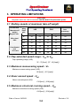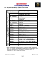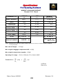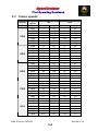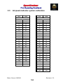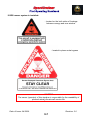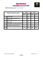
1
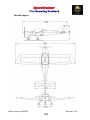
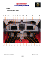
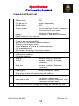
CZECH SPORT AIRCRAFT
OFFICE: ROHÁČOVA 188/37, 130 00, PRAHA 3, CZECH REPUBLIC
PRODUCTION FACILITY: NA ZÁHONECH Č.E. 212, KUNOVICE, 686 04,
CZECH REPUBLIC
www.czechsportaircraft.com
Registration:
Serial Number:
xxSCxxx
This airplane must be operated in compliance with
information and limitations contained in herein.
This POH must be available on board of the airplane.
SECTION 1
1. GENERAL INFORMATION
1.1 Table of contents
1-2
1.2 Record of revisions
1-3
1.3 List of effective pages
1-4
1.4 General
1-6
1.5 Warnings, cautions and notes
1-6
1.6 Definitions and abbreviations
1-7
Date of Issue: 04/2009
Revision: 3.0
1-1
1. GENERAL INFORMATION
1.1 Table of contents
Section
GENERAL INFORMATION......................................................... 1
AIRPLANE AND SYSTEMS DESCRIPTION.............................. 2
OPERATING LIMITATIONS ....................................................... 3
WEIGHT AND BALANCE INFORMATION................................. 4
PERFORMANCE ........................................................................ 5
EMERGENCY PROCEDURES ................................................... 6
NORMAL PROCEDURES .......................................................... 7
AIRPLANE HANDLING,SERVICING AND MAINTENANCE ..... 8
REQUIRED PLACARDS AND MARKINGS ............................... 9
SUPPLEMENTARY INFORMATIONS........................................ 10
Date of Issue: 04/2009
Revision: 3.0
1-2
Revision No.
1.2 Record of revisions
Affected pages
1.0
All
2.0
All
Reason for revision
Initial
Date of Issue
Signature
01/2007
CH.W.E.
12/2007
CH.W.E.
07/2008
CH.W.E.
Pitot static probe change.
Valid for Pitot static probe
“AVIATIK” WA037383 only!
Control surfaces deflection,
2.1
All
formal faults removal.
Valid for Pitot static probe
“AVIATIK” WA037383 only!
3.0
All
Reissue
04/2009
Date of Issue: 04/2009
Revision: 3.0
1-3
1.3 List of effective pages
Section
Page
1
1-1
04/2009
1-2
04/2009
1-3
2
Date of Issue Section
Page
Date of Issue
3-1
04/2009
3-2
04/2009
04/2009
3-3
04/2009
1-4
04/2009
3-4
04/2009
1-5
04/2009
3-5
04/2009
1-6
04/2009
1-7
04/2009
1-8
04/2009
4-1
04/2009
4-2
04/2009
4-3
04/2009
4-4
04/2009
3
4
2-1
04/2009
4-5
04/2009
2-2
04/2009
4-6
04/2009
2-3
04/2009
4-7
04/2009
2-4
04/2009
4-8
04/2009
2-5
04/2009
2-6
04/2009
2-7
04/2009
2-8
04/2009
2-9
04/2009
5-1
04/2009
2-10
04/2009
5-2
04/2009
2-11
04/2009
5-3
04/2009
2-12
04/2009
5-4
04/2009
2-13
04/2009
5-5
04/2009
2-14
04/2009
5-6
04/2009
5
Date of Issue: 04/2009
Revision: 3.0
1-4
Section
Page
Date of Issue Section
Page
Date of Issue
6
6-1
04/2009
8-1
04/2009
6-2
04/2009
8-2
04/2009
6-3
04/2009
8-3
04/2009
6-4
04/2009
8-4
04/2009
6-5
04/2009
8-5
04/2009
6-6
04/2009
6-7
04/2009
6-8
04/2009
9-1
04/2009
9-2
04/2009
9-3
04/2009
8
9
7
7-1
04/2009
9-4
04/2009
7-2
04/2009
9-5
04/2009
7-3
04/2009
9-6
04/2009
7-4
04/2009
9-7
04/2009
7-5
04/2009
7-6
04/2009
7-7
04/2009
7-8
04/2009
10-1
04/2009
7-9
04/2009
10-2
04/2009
7-10
04/2009
10-3
04/2009
10-4
04/2009
10
Date of Issue: 04/2009
Revision: 3.0
1-5
1.4 General
SportCruiser is a Light Sport Aircraft (LSA) designed and built in :
OFFICE: ROHÁČOVA 188/37, 130 00, PRAHA 3, CZECH REPUBLIC
PRODUCTION FACILITY:
NA ZÁHONECH Č.E. 212, KUNOVICE, 686 04, CZECH REPUBLIC
www.czechsportaircraft.com
based on FAA Light Sport Aircraft category according to ASTM Standards
F2245, F2279 and F 2295.
This Pilot Operating Handbook has been prepared to provide pilots with
information for the safe and efficient operation of SportCruiser. It also
contains supplemental data supplied by the Aircraft Flight Training
Supplement.
1.5 Warnings, cautions and notes
The following definitions apply to warnings, cautions and notes in the Pilot
Operating Handbook.
WARNING
Means that the non-observation of the corresponding procedure leads to
an immediate or important degradation of the flight safety i.e. to injury or
death of persons.
CAUTION
Means that the non-observation of the corresponding procedure leads to
a minor or possible long term degradation of the flight safety.
NOTE
Draws attention to any special item not directly related to safety but
which is important or unusual.
Date of Issue: 04/2009
Revision: 3.0
1-6
1.6 Definitions and abbreviations
ADI
ALT
ATC
ASI
bar
BEACON
°C
CAS
CDI
CHT
COMM
EFIS
ELT
EMS
°F
ft
fpm
GPS
hp
IAS
IC
IFR
in
ISA
KCAS
kg
KIAS
km
km/h
knot
kW
l
lb
lbf
m
mm
MAC
max.
min.
mph
Atitude direction indicator
Altitude or Altimeter
Air Taffic Control
Airspeed Indicator
pressure unit
(1 bar = 14.5037 psi)
anti-collision beacon
temperature in degree of Celsius
(1°C = (°F - 32) / 1.8)
Calibrated Airspeed
Course deviation indicator
Cylinder head temperature
Communication transceiver
Electronic Flight Instrument System
Emergency Locator Transmitter
Engine Monitoring System
temperature in degree of Fahrenheit
(1°F = (°C x 1.8) + 32)
foot or feet
(1 ft = 12 in = 0.305 m = 305 mm)
vertical speed in feet per minute
(1 fpm = 0.0051 m/s)
Global Positioning System
power unit
(1 hp = 0.7457 kW)
Indicated Airspeed
Intercom
Instrument Flight Rules
inch
(1 in = 25.4 mm)
International Standard Atmosphere
Calibrated Airspeed in Knots
kilogram
(1 kg = 2.205 lb)
Indicated Airspeed in Knots
kilometer
(1 km = 1000 m = 0.54 NM = 0.621 SM)
speed in kilometer per hour
(1 km/h = 0.54 knots = 0.621 mph = 0.278 m/s)
speed in NM per hour
(1 knot = 1.151 mph = 1.852 km/h = 0.514 m/s)
power unit
(1 kW = 1.341 hp)
litre
(1 l = 0.22 UK gal = 0.264 US gal)
pound
(1 lb = 0.454 kg)
force unit
(1 lbf = 4.448 N)
metre
(1 m = 1000 mm = 3.28 ft = 39.37 in)
milimeter
(1 mm = 0.03937 in)
Mean Aerodynamic Chord
maximum
minimum or minute
speed in statute miles per hour
(1 mph = 0.87 knots = 1.61 km/h)
Date of Issue: 04/2009
Revision: 3.0
1-7
m/s
N
NM
OFF
ON
OAT
POH
psi
rpm
s or sec
SM
US gal
V
VFR
VMC
VSI
VTU
VA
VFE
VNE
VNO
VSO
VS1
VX
VY
speed in meter per second
(1 m/s = 196.8 fpm = 1.944 knots = 3.6 km/h)
Newton - force unit
(1 N = 0.225 lbf)
Nautical Mile
(1 NM = 1852 m)
system is switched off or control element is in off-position
system is switched on or control element is in on-position
Outside Air Temperature
Pilot Operating Handbook
pressure unit - pound per square inch
(1psi = 0.0689bar)
revolutions per minute
second
Statute Mile
(1SM = 1,609 m)
US gallon
(1 US gal = 0,83 UK gal = 3,785 l)
Volt
Visual Flight Rules
Visual Meteorological Conditions
Vertical Speed Indicator
vertical tail unit
maneuvering airspeed
maximum flap extended speed
never exceed speed
maximum designed cruising speed
stall speed with wing flaps in extended position
stall speed with wing flaps in retracted position
best angle of climb speed
best rate of climb speed
Date of Issue: 04/2009
Revision: 3.0
1-8
SECTION 2
2. AIRPLANE AND SYSTEMS DESCRIPTION
2.1 Airplane description
2-2
2.2 Engine
2-10
2.3 Propeller
2-12
2.4 Fuel system
2-12
2.5 Oil
2-13
2.6 Operating weights and loading
2-14
Date of Issue: 04/2009
Revision: 3.0
2-1
2. AIRPLANE AND SYSTEMS DESCRIPTION
This section provides description and operation of the aircraft and its
systems.
2.1 Airplane description
SportCruiser is the airplane intended especially for recreational and crosscountry flying, and non-aerobatics operation.
SportCruiser is a single-engine, all metal, low-wing monoplane of semimonocoque construction with two side-by-side seats. The airplane is
equipped with a fixed tricycle undercarriage with castering nose wheel.
Airplane dimensions
Wing span ............................................ 28.90 [ft]
(8.81 [m])
Length ..................................................21.33 [ft]
(6.50 [m])
Height................................................... 7.78 [ft]
(2.37 [m])
Wing area............................................. 132.3 [sq ft]
(12.3 [m2])
Wing loading ........................................ 10 [lb/sq ft]
(49 [kg/m2])
Cockpit width ........................................46 [in]
(1.17 [m])
Date of Issue: 04/2009
Revision: 3.0
2-2
Aircraft layout
Date of Issue: 04/2009
Revision: 3.0
2-3
Airframe
All-metal construction, stressed skin, single curvature metal skins riveted
to stiffeners. Construction is of 6061-T6 aluminum sheet metal riveted to
aluminum angles with Avex rivets. This high strength aluminum alloy
construction provides long life and low maintenance costs thanks to its
durability and corrosion resistance characteristics.
The wing has a high lift airfoil equipped with flaps.
Control system
The plane is equipped with a dual stick control, the adjustable rudder
pedals with pedal hydraulic brakes for easy ground control of the castering
nose wheel.
The elevator and aileron trim are electrically actuated by buttons on the
control stick. Wing flaps are electrically actuated by the rocker switch
located on the middle panel.
Deflections:
Rudder deflections ............................... 30° to each side
Elevator deflections .............................. + 28°/- 25°
Aileron deflections ................................ + 20°/- 15°
Flap deflections .................................... 0° to 30°
Aileron trim deflections ......................... + 20°/- 20°
Elevator trim deflections ....................... + 22°/- 28°
Landing gear
Tricycle landing gear with the castering nose wheel. Main landing gear
uses two fiberglass spring elements.
Date of Issue: 04/2009
Revision: 3.0
2-4
Seats and safety harness
Side-by-side seating. Seat cushions are removable to make more easy
cleaning and drying. Four point safety belts provided to each seat.
Additional seat upholstery to raise the small pilot or move him forward can
be the option.
NOTE
Prior to each flight, ensure that the seat belts are firmly secured to the
airframe and that the belts are not damaged. The buckle to adjust to
the central position on the body.
Baggage compartment
The rear baggage compartment is located behind the seats. It may
accommodate up to 40 [lb] (18 [kg]). This space is divide on two sections –
baggage compartment A and B. Is not recommended give too heavy
things into baggage compartment B.
The baggage may also be loaded into the baggage compartment inside
each wing up to 44 [lb] (20 [kg]), in each wing locker.
Make sure that baggage does not exceed maximum allowable weight, and
that the aircraft C.G. is within limits with loaded baggage.
All baggage must be properly secured.
Canopy
Access to the cabin is from both sides. Make sure that the canopy is
latched and mechanism is securely locked into position on both sides
before operating the aircraft.
Pitot - static system
Standard AVIATIK WA037383 pitot-static probe is located below the left
wing. Pressure distribution to the instruments is through flexible plastic
hoses. Keep the pitot head clean to ensure proper function of the system.
Date of Issue: 04/2009
Revision: 3.0
2-5
Cockpit
Instrument panel layout
1
14
2
3
15
4
16
5
6
17
7
8
9
18
19
20
10
21
Date of Issue: 04/2009
11
22
12
23
24
13
25
26
Revision: 3.0
2-6
15
Description of instrumentation and controls in the cockpit
1
Parking brake
14
Ignition switch
2
Backup Altimeter
15
PTT / elevator trim /
aileron trim buttons
3
Backup Airspeed indicator
16
Switches
4
EFIS
17
PS Intercom
5
EMS warning light
18
Flaps control switch
6
Aileron trim indicator
19
Flaps position indicator
7
Elevator trim indicator
20
Throttle
8
Transceiver
21
Choke
9
GPS
22
Fuel selector valve
10
Compass
23
Socket 12V
11
Transponder
24
Carburetors preheating
12
EMS
25
Cabin heating
13
ELT control unit
26
Circuit breakers
Date of Issue: 04/2009
Revision: 3.0
2-7
Instruments and Avionics
•
•
•
•
•
•
•
•
•
•
•
Dynon D100 EFIS
Dynon D120 EMS
Backup Airspeed indicator
Backup Altimeter
Compass
Garmin SL40 transceiver
PS Engineering PM3000 stereo intercom
Garmin GTX327 transponder
Garmin 296 GPS
Artex ME406 ELT
Antennas
Miscellaneous equipment
•
•
•
•
•
•
•
•
•
•
•
•
G -205 trim control and PTT on the control sticks
Trims and flaps electrically actuated
Kuntzleman wing tip strobe/nav. lights
Landing light in cowl
Adjustable pedals
Dual hydraulic brakes
Parking brake
Wheel fairings tricycle
Cabin heating
Carburetors preheating
Leather upholstery
Paint
NOTE
For operating instructions refer to the documentation supplied with the
instruments
Date of Issue: 04/2009
Revision: 3.0
2-8
Minimum instruments and equipment list for VFR flights:
-
Airspeed indicator
Altimeter
Compass (is not required by ASTM F 2245)
Fuel quantity indicator
Tachometer (RPM)
Engine instruments as required by
the engine manufacturer :
- Oil temperature indicator
- Oil pressure indicator
- Cylinder head temperature indicator
Date of Issue: 04/2009
Revision: 3.0
2-9
2.2 Engine
ROTAX 912 ULS engine 98.6 [hp]73.5 [kW] (73.5 [kW]) is installed in
SportCruiser. Rotax 912 ULS is a 4-stroke, 4 cylinder, horizontally
opposed, spark ignition engine with one central camshaft-push-rod-OHV.
Liquid cooled cylinder heads, ram air cooled cylinders.
Dry sump forced lubrication. Dual contactless capacitor discharge ignition.
The engine is fitted with an electric starter, AC generator and mechanical
fuel pump. Prop drive via reduction gear with integrated shock absorber.
Coolant
Coolant type:
(refer to the ROTAX the Rotax Operator’s manual section 10.1.2 Operating
speeds and limits and section 10.2.1 Coolant, Rotax Installation manual
section 12 Cooling system, Rotax Service Instruction SI-912-016)
In principle, 2 different types of coolant are permitted:
-
Conventional coolant based on ethylene glycol
-
Waterless coolant based on propylene glycol
WARNING
The coolant concentrate (propylen glycol) may not be mixed with
conventional (glycol/water) coolant or with additives!
Non observance can lead to demages to the cooling system and engine.
CAUTION
Conventional glycol/water coolant reduce to apply the maximum
permissible coolant exit temperature.
Type of coolant used by aircrafts manufacturer:
- see section 10.2 Supplement No.2
Coolant liquid volume:
It is approximately ......................................0.66 [US gal]
Date of Issue: 04/2009
(2.5 [litre])
Revision: 3.0
2-10
Throttle and Choke
Engine power is controlled by means of the THROTTLE lever with the
CHOKE lever which are positioned in the middle channel between the
seats side by side. Both levers are mechanically connected (by cable) to
the flap on the carburetors. Springs are added to the throttle push rods to
ensure that the engine will go to full power if the linkages fail.
Carburetors preheating
Heated air streaming from a heat exchanger to the carburetors through the
airbox. The control lever is installed on the middle panel.
Heating
Heating consists of a heat exchanger on the exhaust manifold and
actuator located on the instrument panel.
CAUTION
Incidents involving exhaust gases entering the heating or ventilation
system may result in fatal accidents due to carbon monoxide poisoning
of the aircraft occupants. A carbon monoxide detector is recommended.
Electrical system
Battery
The 12 [V] battery is mounted on the front side of forward bulkhead.
Master switch
Master switch connects the electrical system to the 12 [V] battery.
NOTE
Ignition system is independent on the power source and will operate
even with Master switch and/or breaker off.
Date of Issue: 04/2009
Revision: 3.0
2-11
Ignition Switch
Ignition switch must be on “BOTH” position to operate the engine. For
safety remove the key when engine is not running.
NOTE
All switches or engine controls are "up" or "push forward" for operation,
except the choke, cabin heating and carburetor preheat, which is "Pull"
for "On". Optional equipment, switches and/or circuit breakers are
subject to change or installed as requested. See Aircraft Equipment List
and Instrument panel layout and Description of equipment and controls
in the cockpit.
2.3 Propeller
Standard WOODCOMP KLASSIC 170/3/R three composite blade in
ground adjustable propeller is installed.
NOTE
For technical data refer to documentation supplied by the propeller
manufacturer
2.4 Fuel system
Each tank is equipped with a vent outlet and finger screen filter.
Drain valve located in the lowest point of the each tank and on the bottom
edge of the bulkhead, on the gascollator.
Main fuel selector valve is on the central console in the cockpit.
The electric fuel pump is located on bulkhead.
CAUTION
Do not overfill the tanks to avoid fuel overflow through venting tubes.
Date of Issue: 04/2009
Revision: 3.0
2-12
Recommended fuel type:
(refer to the ROTAX Operator’s manual section 10.2.2 Fuel,
Rotax Service Instruction SI-912-016)
MOGAS
European standard
- min. RON 95, EN 228 Super, EN 228 Super plus
US standard
- ASTM D4814
Canadian standard
- min. AKI 91, CAN/CGSB-3.5 Quality 3
AVGAS
US standard
- AVGAS 100 LL (ASTM D910)
AVGAS 100 LL places greater stress on the valve seats due to its high lead content
and forms increased deposits in the combustion chamber and lead sediments in the
oil system. Thus it should only be used in case of problems with vapor lock or when
other types of gasoline are unavailable.
Fuel volume:
Wing fuel tank volume ..........................2x15.06 [US gal] (2x57 [litre])
Unusable fuel quantity ..........................2x0.13 [US gal] (2x0.5 [litre])
2.5 Oil
Oil type:
(refer to the Rotax Operator’s manual section 10.2.3 Lubricants,
Rotax Service Instruction SI-912-016)
Motorcycle 4-stroke engine oil of registered brand with gear additives.
Use only oil with API classification „SG“ or higher!
Use of multi-grade no mineral oils is recommended.
Type of oil used by aircrafts manufacturer:
- see section 10.2 Supplement No.2
Oil volume:
Minimum ...............................................0.87 [US gal]
Maximum ..............................................1.0 [US gal]
Date of Issue: 04/2009
(3.3 [litre])
(3.8 [litre])
Revision: 3.0
2-13
2.6 Operating weights and loading
Empty weight (standard equipment) .................... 760 [lb]
(345 [kg])
NOTE
Actual empty weight is shown in section 4
LSA Max. take-off weight..................................... 1 320 [lb]
(600 [kg])
Max landing weight.............................................. 1 320 [lb]
(600 [kg])
Max. weight of fuel .............................................. 180 [lb]
(82 [kg])
Max. baggage weight in rear fuselage................. 40 [lb]
(18 [kg])
Max. baggage weight in each wing locker ........... 44 [lb]
(20 [kg])
WARNING
Do not exceed maximum take-off weight 1 320 [lb] (600 [kg]) !
Number of seats................................................. 2
Minimum crew.................................................... 1 pilot on the left seat
Minimum crew weight......................................... 95 [lb]
(43 [kg])
Maximum crew weight........................................ see section 4
Date of Issue: 04/2009
Revision: 3.0
2-14
SECTION 3
3. OPERATING LIMITATIONS
3.1 Stalling speeds
3-2
3.2 Flap extended speed range
3-2
3.3 Maximum maneuvering speed
3-2
3.4 Never exceed speed
3-2
3.5 Maximum structural cruising speed
3-2
3.6 Crosswind and wind limitations
3-3
3.7 Service ceiling
3-3
3.8 Load factor
3-3
3.9 Prohibited maneuvers
3-3
3.10 Engine operating speeds and limits
3-4
3.11 Other limitations
3-5
Date of Issue: 04/2009
Revision: 3.0
3-1
3. OPERATING LIMITATIONS
CAUTION
Airspeeds values are valid for standard AVIATIK WA037383 pitot-static probe.
3.1 Stalling speeds at maximum take-off weight
Conditions:
Max.take-off
weight
Engine: idle
Wing level
stall
Coordinated
turn
30° bank
Wing
flaps
pos.
IAS
Altitude
loss
at recovery
CAS
knot
mph
knot
mph
ft
0°
39
45
43
49
65
15°
35
40
39
45
49
30°
32
37
37
43
33
0°
42
48
46
53
82
15°
38
44
42
48
66
30°
35
40
39
45
49
3.2 Flap extended speed range - VS0 to VFE
Flap operating range (IAS):
32 - 75 [knot] (37 - 86 [mph])
3.3 Maximum maneuvering speed - VA
Maximum maneuvering speed (IAS):
88 [knot] (101 [mph])
3.4 Never exceed speed - VNE
Never exceed speed (IAS):
138 [knot] (158 [mph])
3.5 Maximum structural cruising speed – VNO
Maximum structural cruising speed (IAS):
108 [knot] (124 [mph])
Date of Issue: 04/2009
Revision: 3.0
3-2
3.6 Crosswind and wind limitation
Demonstrated wind performance
Max. demonstrated head wind velocity
for take-off and landing .............................................. 24 [knot]
Max. demonstrated cross wind velocity
for take-off and landing .............................................. 12 [knot]
3.7 Service ceiling
Service ceiling............................................................ 10 000 [ft]
3.8 Load factor
Maximum positive limit load factor ............................. +4 g
Maximum negative limit load factor ............................ - 2 g
3.9 Prohibited maneuvers
WARNING
AEROBATICS AND INTENTIONAL SPINS ARE PROHIBITED !
Airplane Category: LSZ
The SportCruiser is approved for normal and below listed maneuvers:
•
Steep turns not exceeding 60° bank
•
Lazy eights
•
Chandelles
•
Stalls (except whip stalls)
Date of Issue: 04/2009
Revision: 3.0
3-3
3.10 Engine operating speeds and limits
98.6 hp (73.5 kW)
at 5800 rpm (max. 5 min.)
Max. Continuous:
92.5 hp (69 kW)
at 5500 rpm
Cruising:
71 hp (53 kW)
at 4800 rpm
Max. Take-off:
5800 rpm
Max. Continuoust:
5500 rpm
Cruising:
4800 rpm
Idling:
1400 rpm
Minimum:
122° F (50° C)
Maximum:
275 ° F (135 ° C)
Optimum:
167 - 230° F (75 - 110° C)
Minimum:
122° F (50° C)
Maximum:
266° F (130° C)
Optimum:
194 - 230° F (90 - 110° C)
Minimum:
12 psi (0.8 bar) - below 3500 rpm
Maximum:
102 psi (7 bar) - cold engine starting
Optimum:
29 - 73 psi (2 - 5 bar) - above 3500 rpm
Minimum:
2.2 psi (0.15 bar)
Maximum:
5.8 psi (0.4 bar)
Engine RPM
Power
Max Take-off:
Cylinder head
temperature:
Bombardier-Rotax GMBH
Oil
temperature
Engine Manufacturer:
Oil pressure:
ROTAX 912 ULS
Fuel
press.
Engine Model:
(max. 5 min.)
(minimum)
*
* see the Rotax Operator’s manual section 10.1.2 Operating speeds and limits and
section 10.2.1 Coolant, Rotax Installation manual section 12 Cooling system, Rotax
Service Instruction SI-912-016, POH section 2.2 Coolant and section 10.2
Supplement No.2 Type of coolant used in engine.
Date of Issue: 04/2009
Revision: 3.0
3-4
3.11 Other limitations
•
No smoking on board of the aircraft !
•
There are permitted Day VFR flights
WARNING
IFR FLIGHTS AND INTENTIONAL FLIGHTS UNDER ICING
CONDITIONS ARE PROHIBITED!
Flight in rain
When flying in the rain, no additional steps are required.
Aircraft qualities and performance are not substantially changed. However
VMC must be maintained !
Date of Issue: 04/2009
Revision: 3.0
3-5
SECTION 4
4. WEIGHT AND BALANCE
4.1 Installed equipment list
4-2
4.2 Center of gravity range and determination
4-3
4.3 Permitted payload range
4-8
Date of Issue: 04/2009
Revision: 3.0
4-1
4. WEIGHT AND BALANCE INFORMATION
This section contains weight and balance records and the payload range for
safe operating of SportCruiser.
4.1 Installed equipment list
•
•
•
•
•
•
•
•
•
•
•
•
•
•
•
•
•
•
•
•
•
•
•
•
•
Rotax 912 ULS with airbox
engine
s/n: xxxxxxx
Woodcomp KLASSIC 170/3/R
propeller
s/n: xxxx683R
Dynon D100 EFIS
Dynon D120 EMS
Backup Airspeed indicator
Backup Altimeter
Compass
Garmin SL40 transceiver
PS Engineering PM3000 stereo intercom
Garmin GTX327 transponder
Garmin 296 GPS
Artex ME406 ELT
Antennas
G -205 trim control and PTT on the control sticks
Trims and flaps electrically actuated
Kuntzleman wing tip strobe/nav. lights
Landing light in cowl
Adjustable pedals
Dual hydraulic brakes
Parking brake
Wheel fairings tricycle
Cabin heating
Carburetors preheating
Leather upholstery
Paint
xxSCxxx
20xx-xx-xx
Date of Issue: 04/2009
Revision: 3.0
4-2
4.2 Center of gravity (C.G.) range and determination
LSA category
Max. take-off weight ..................................... 1 320 [lb] (600 [kg])
Center of gravity (C.G.)
Operating C.G. range......................................27 to 38 [%] of MAC
15.94 to 22.44 [in] (405 to 570 [mm]) of MAC
Empty weight C.G. range ..............................28 to 32 [%] of MAC
16.54 to 18.90 [in] (420 to 480 [mm]) of MAC
Aircraft C.G. determination
Weight and Balance list of reports:
- C.G. Layout
- Empty Weight C.G. Check
- Forward C.G. Check
- Rearward C.G. Check
Date of Issue: 04/2009
Revision: 3.0
4-3
WEIGHT & BALANCE REPORT
C.G. Layout
Date of Issue: 04/2009
Revision: 3.0
4-4
AIRCRAFT EMPTY C.G.
WEIGHT & BALANCE REPORT
Empty Weight C.G. Check
NOTE:
ITEM
WEIGHT
ARM
MOMENT
[lb]
[in]
(WEIGHT x ARM)
RIGHT MAIN
WHEEL
WR= 313.5
LR=
31.26
9 800.01
LEFT MAIN
WHEEL
WL= 315.9
LL=
30.86
9 748.67
NOSE WHEEL
WN= 176.7
LN= - 28.23
- 4 988.24
Empty weight:
C.G.= 18.06 [in]
COMPUTED
C.G. EMPTY
negative arm
WE= 806.1
Aircraft moment:
30.6 [%] MAC ME = 14 560.44
[lb]
EMPTY WEIGHT INCLUDING OIL, COOLANT AND HYDRAULIC FLUID.
Empty weight C.G. range : 16.54 to 18.90 [in] / 28 to 32 [%] of MAC
Max. take-off weight : 1 320 [lb]
Maximum useful weight :
W Max Useful = W Max Take-Off
W Max Useful = 1320 [lb]
– WE
– 806.1 [lb]
= 513.9 [lb]
This useful weight must be never exceeded!
NOTE:
MAXIMUM USEFUL WEIGHT INCLUDING PILOT, PASSENGER, BAGGAGE AND FUEL.
ME
Aircraft Empty C.G. = ------- [mm]
WE
x
100
-------- [%]
MAC
xxSCxxx
20xx-xx-xx
Date of Issue: 04/2009
Revision: 3.0
4-5
WEIGHT & BALANCE REPORT
Forward C.G. Check
FORWARD C.G.
WEIGHT
ARM
MOMENT
[lb]
[in]
(WEIGHTxARM)
EMPTY AIRCRAFT
806.1
--------
14 560.44
88.0
27.56
2 425.28
0.0
27.56
0.0
0.0
51.58
0.0
0.0
70.87
0.0
0.0
23.62
0.0
180.6
7.09
PILOT
PASSENGER
BAGGAGE
COMPARTMENT - A
BAGGAGE
COMPARTMENT - B
WING LOCKERS
FUEL TANKS
TOTAL
WT=1 074.70
[lb]
MT= 18 266.18
1 074.70
[lb]
C.G.= 17.00 [in]
28.8 [%] MAC
TAKE-OFF WEIGHT
NOTE:
1 280. 45
MAXIMUM FUEL QUANTITY IN WING TANKS (180.62LB =30.1US GAL) IS USED FOR MOST FORWARD
C.G.CALCULATION.
Max. take-off weight : 1 320 [lb]
Max. weight in baggage compartment A+B : 40 [lb]
Max. weight in wing lockers together : 88 [lb]
Operating C.G. range : 15.94 to 22.44 [in] / 27 to 38 [%] of MAC
MT
Forward C.G. = ----- [mm]
WT
x
100
-------- [%]
MAC
xxSCxxx
20xx-xx-xx
Date of Issue: 04/2009
Revision: 3.0
4-6
WEIGHT & BALANCE REPORT
Rearward C.G. Check
REARWARD C.G.
WEIGHT
ARM
MOMENT
[lb]
[in]
(WEIGHT x ARM)
EMPTY AIRCRAFT
806.1
--------
14 560.44
PILOT
190.0
27.56
5 236.40
PASSENGER
190.0
27.56
5 236.40
33.3
51.58
1 722.77
6.7
70.87
467.74
71.7
23.62
2 078.56
0.0
7.09
BAGGAGE
COMPARTMENT - A
BAGGAGE
COMPARTMENT - B
WING LOCKERS
FUEL TANKS
TOTAL
WT=1 297.8
[lb]
MT= 28 919.24
1 297.8
[lb]
CG= 22.28 [in]
37.7 [%] MAC
TAKE-OFF WEIGHT
NOTE:
0.0
MINIMUM FUEL QUANTITY IN WING TANKS FOR 30MINUTE FLIGHT (22.2LB=3.7US GAL) IS SUBTRACTED
FROM MTOW (1320LB). MOST REARWARD C.G. CALCULATION IS DONE WITH ZERO FUEL QUANTITY
(AFTER FUEL DEPLETION).
Max. take-off weight : 1 320 [lb]
Max. weight in baggage compartment A+B : 40 [lb]
Max. weight in wing lockers together : 88 [lb]
Operating C.G. range : 15.94 to 22.44 [in] / 27 to 38 [%] of MAC
MT
Rearward C.G. = ------- [mm]
WT
x
100
-------- [%]
MAC
Serial No.: xxSCxxx
Date:
20xx-xx-xx
By:
Date of Issue: 04/2009
Revision: 3.0
4-7
4.3 Permitted payload range
SportCruiser
F
U
E
L
gauges together
volume
weight
US gal
litre
lb
kg
Serial No. : xxSCxxx
for 30 min
flight
1/4
1/2
3/4
1
3.7
14
22.2
10.1
7.5
28.5
45.1
20.5
15.1
57
90.3
41
22.6
85.5
135.4
61.6
30.1
114
180.6
82.1
Permitted crew weight
lb
492
469
424
379
333
kg
224
213
193
172
152
lb
472
449
404
359
313
kg
214
204
183
163
142
No baggage
½ rear (A)
20 [lb] (9 [kg])
B
rear (A)
40 [lb] (18 [kg])
lb
452
429
384
339
293
kg
205
195
174
154
133
½ wing lockers
lb
448
425
380
335
289
44 [lb] (20 [kg])
kg
204
193
173
152
132
½ rear (A) + ½ wing lockers
lb
428
405
360
315
269
64 [lb] (29 [kg])
kg
194
184
163
143
122
rear (A) + ½ wing lockers
84 [lb] (38 [kg])
lb
408
385
340
295
249
kg
185
175
154
134
113
A
G
G
A
G
E
wing lockers
88 [lb] (40 [kg])
lb
404
381
336
291
245
kg
184
173
153
132
112
½ rear (A) + wing lockers
lb
384
361
316
271
225
108 [lb] (49 [kg])
kg
174
164
143
123
102
rear (A) + wing lockers
128 [lb] (58 [kg])
lb
364
341
296
251
205
kg
165
155
134
114
93
Crew weight = Max.Take-off weight - Empty weight - Baggage weight - Fuel weight
Crew weight values must be determine with regard on rearward C.G. limit.
Max. take-off weight : 1 320 [lb] (600 [kg])
Date of Issue: 04/2009
20xx-xx-xx
Revision: 3.0
4-8
SECTION 5
5. PERFORMANCE
5.1 Take-off and landing distances
5-3
5.2 Rate of climb
5-3
5.3 Cruise speeds
5-4
5.4 Fuel consumption
5-5
5.5 Airspeed indicator system calibration
5-6
Date of Issue: 04/2009
Revision: 3.0
5-1
5. PERFORMANCE
The presented data has been computed from actual flight tests with the
aircraft and engine in good conditions and using average piloting
techniques.
If not stated otherwise, the performance stated in this section is valid for
maximum take-off weight and under ISA conditions.
The performance shown in this section is valid for aircraft fitted with given
ROTAX 912 ULS 98.6 [hp] (73.5 [kW]) engine and WOODCOMP KLASSIC
170/3/R propeller.
CAUTION
Airspeeds values are valid for standard AVIATIK WA037383 pitot-static probe.
Date of Issue: 04/2009
Revision: 3.0
5-2
5.1 Take-off and landing distances
Take-off distances:
Take-off run distance
Take-off distance over
50 ft obstacle
ft
ft
CONCRETE
328
820
GRASS
361
918
Landing distance over
50 ft obstacle
Landing run distance
(braked)
ft
ft
CONCRETE
591
180
GRASS
558
197
RUNWAY
SURFACE
Landing distances:
RUNWAY
SURFACE
5.2 Rate of climb
Conditions:
Best rate of
climb speed
Rate of climb
Vz
Max. continuous power:
5500 [rpm]
Max. take-off weight:
1 320 [lb] (600 [kg])
knot
mph
fpm
0 ft
65
75
1200
3000 ft
65
75
850
6000 ft
60
70
550
9000 ft
55
63
315
Date of Issue: 04/2009
Revision: 3.0
5-3
5.3 Cruise speeds
Altitude
ft
1000
3000
5000
7000
9000
Engine
speed
rpm
4200
4500
4800
5000
5300
5500
5800
4200
4500
4800
5000
5300
5500
5800
4200
4500
4800
5000
5300
5500
5800
4200
4500
4800
5000
5300
5500
5800
4200
4500
4800
5000
5300
5500
5800
IAS
knot
77
86
95
101
110
116
125
75
83
92
97
106
112
120
72
80
88
94
102
107
116
69
77
84
90
97
103
111
65
73
80
85
93
98
105
CAS
mph
89
99
109
116
126
133
143
86
96
106
112
122
129
139
83
92
101
108
117
124
134
79
88
97
103
112
118
127
75
84
93
98
107
112
121
Date of Issue: 04/2009
knot
77
85
93
98
106
111
119
75
82
90
95
103
108
116
72
79
86
92
99
104
112
70
77
83
88
95
100
107
66
73
80
84
91
95
102
mph
88
98
107
113
122
128
137
86
94
104
109
118
124
133
83
91
99
106
114
120
129
80
88
96
101
109
115
123
76
84
92
97
104
109
117
Revision: 3.0
5-4
5.4 Fuel consumption
The table below shows fuel consumption, endurance and range
ft
3000
Usable fuel
quantity
US gal
29.86
litre
113
Engine speed
rpm
4200
4500
4800
5000
5300
5500
Fuel
consumption
US gal/h
3,04
3.70
4.36
4.89
5.55
6.08
l/h
11.5
14.0
16.5
18.5
21.0
23.0
knot
75
83
92
97
106
112
Airspeed
Altitude
IAS
mph
86
94
104
109
118
124
knot
75
82
90
95
103
108
mph
86
94
104
109
118
124
hh:mm
9:49
8:04
6:51
6:06
5:23
4:55
NM
737
662
616
580
554
530
SM
845
759
712
666
635
609
CAS
Endurance
Range
Date of Issue: 04/2009
Revision: 3.0
5-5
5.5
Airspeed indicator system calibration
IAS
CAS
IAS
knot
CAS
mph
30
35
35
41
35
39
40
45
40
44
45
49
45
48
50
54
50
53
55
58
55
57
60
63
60
62
65
67
65
66
70
72
70
71
75
76
75
75
80
81
80
79
85
85
85
84
90
89
90
88
95
94
95
93
100
98
100
97
105
103
105
102
110
107
110
106
115
112
115
111
120
116
120
115
125
121
125
120
130
125
130
124
135
130
135
129
140
134
140
133
145
139
150
143
155
148
160
152
Date of Issue: 04/2009
Revision: 3.0
5-6
SECTION 6
6. EMERGENCY PROCEDURES
6.1 Engine failure
6-2
6.2 In-flight engine starting
6-3
6.3 Smoke and fire
6-3
6.4 Glide
6-5
6.5 Landing emergencies
6-5
6.6 Recovery from unintentional spin
6-7
6.7 Other emergencies
6-7
Date of Issue: 04/2009
Revision: 3.0
6-1
6. EMERGENCY PROCEDURES
This section provides checklists and amplified procedures for coping with
various emergencies that may occur. Emergencies caused by aircraft or
engine malfunction are extremely rare if proper pre-flight inspections and
maintenance are practiced.
However, should an emergency arise, the basic guidelines described in this
section should be considered and applied as necessary to correct the
problem.
CAUTION
Airspeeds values are valid for standard AVIATIK WA037383 pitot-static probe.
These emergency procedures are valid for standard WOODCOMP KLASSIC
170/3/R three composite blade in ground adjustable propeller.
6.1 Engine Failure
6.1.1
Engine failure during take-off run
1. Throttle
- reduce to idle
2. Ignition switch
- switch off
3. Apply brakes
6.1.2
Engine failure during take-off
1. Speed
- gliding at 60 [knot] (70 [mph])
2. Altitude
- below 150 [ft] : land in take-off direction
- over 150 [ft] : choose a landing area
3. Wind
- find direction and velocity
4. Landing area
- choose free area without obstacles
5. Flaps
- extend as necessary
6. Fuel Selector
- close
7. Ignition switch
- switch off
8. Safety harness
- tighten
9. Master switch
- switch off before landing
10. Land
Date of Issue: 04/2009
Revision: 3.0
6-2
6.1.3
Engine failure in flight
1. Push control stick forward
2. Speed
- gliding at 60 [knot] (70 [mph]))
3. Altitude
- below 150 [ft] : land in take-off direction
- over 150 [ft] : choose a landing area
4. Wind
- find direction and velocity
5. Landing area
- choose free area without obstacles
6. Flaps
- extend as necessary
7. Fuel Selector
- close
8. Ignition switch
- switch off
9. Safety harness
- tighten
10. Master switch
- switch off before landing
11. Land
6.2 In-flight Engine Starting
1. Switches
- switch off unnecessary electrical equipment
2. Master switch
- switch on
3. Fuel Selector
- turn on (to tank with more quantity of fuel)
4. Throttle
- idle
5. Electric pump
- switch on
6. Ignition switch
- hold activated to start the engine
7. After engine starting - electric pump - switch off
- other switches - switch on as necessary
6.3 Smoke and Fire
6.3.1
Fire on ground at engine starting
1. Fuel Selector
- close
2. Throttle
- full power
3. Ignition switch
- switch off
4. Leave the airplane
5. Extinguish fire by fire extinguisher or call for a fire-brigade if you
cannot do it.
Date of Issue: 04/2009
Revision: 3.0
6-3
6.3.2
1.
2.
3.
4.
5.
6.
6.3.3
1.
2.
3.
4.
5.
6.
7.
6.3.4
Fire on ground with engine running
Heating
- close
Fuel selector
- close
Throttle
- full power
Ignition switch
- switch off
Leave the airplane
Extinguish fire by fire extinguisher or call for a fire-brigade if you
cannot do it.
Fire during take-off
Speed
- 60 [knot] (70 [mph])
Heating
- close
Fuel Selector
- close
Throttle
- full power
Ignition switch
- switch off
Land, stop and leave the airplane
Extinguish fire by fire extinguisher or call for a fire-brigade if you
cannot do it.
Fire in flight
1. Heating
2. Fuel Selector
- close
- close
3. Throttle
- full power
4. Master switch
- switch off
5. Ignition switch
- switch off after the fuel in carburetors is
consumed and engine shut down
6. Choose of area
- heading to the nearest airport or choose
emergency landing area
7. Emergency landing - perform according to 6.5.1
8. Leave the airplane
9. Extinguish fire by yourself or call for a fire-brigade if you cannot do it.
Date of Issue: 04/2009
Revision: 3.0
6-4
NOTE
Estimated time to pump fuel out of carburetors is
about 30 [sec].
WARNING
Do not attempt to re-start the engine!
6.3.5
Fire in the cockpit
1. Master switch
- switch off
2. Heating
- close
3. Use the fire extinguisher (if installed)
6.4 Glide
An example of the use of gliding is in the case of engine failure
1. Speed - recommended gliding speed 60 [knot] (70 [mph])
6.5 Landing Emergencies
6.5.1
Emergency landing
Emergency landings are generally carried out in the case of engine failure
and the engine cannot be re-started.
1. Speed - adjust for optimum gliding 60 [knot] (70 [mph])
2. Trim
- adjust
3. Safety harness
- tighten
4. Flaps
- extend as necessary
5. COMM
- if installed then report your location if possible
6. Fuel Selector
- close
7. Ignition switch
- switch off
8. Master switch
- switch off
9. Perform approach without steep turns and land on chosen landing
area.
Date of Issue: 04/2009
Revision: 3.0
6-5
6.5.2
Precautionary landing
A precautionary landing is generally carried out in the cases where the
pilot may be disorientated, the aircraft has no fuel reserve or possibly in
bad weather conditions.
1. Choose landing area, determine wind direction
2. Report your intention to land and land area location if a COMM is
installed in the airplane.
3. Perform low-altitude passage into wind over the right-hand side of the
chosen area with flaps extended as needed and thoroughly inspect the
landing area.
4. Perform circle pattern.
5. Perform approach at increased idling with flaps fully extended.
6. Reduce power to idle when flying over the runway threshold and touchdown at the very beginning of the chosen area.
7. After stopping the airplane switch off all switches, shut off the fuel
selector, lock the airplane and seek for assistance.
NOTE
Watch the chosen area steadily during precautionary landing.
6.5.3
Landing with a flat tire
1. During landing keep the damaged wheel above ground as long as
possible using the ailerons control
2. Maintain the direction on the landing roll out, applying rudder control.
6.5.4
Landing with a defective landing gear.
1. If the main landing gear is damaged, perform touch-down at the lowest
practicable speed and if possible, maintain direction during landing
run.
2. If the nose wheel is damaged perform touch-down at the lowest
practicable speed and hold the nose wheel above the ground by
means of the elevator control as long as possible.
Date of Issue: 04/2009
Revision: 3.0
6-6
6.6 Recovery from Unintentional Spin
WARNING
Intentional spins are prohibited!
There is no an uncontrollable tendency of the airplane to enter into a spin
provided the normal piloting techniques are used.
Unintentional spin recovery technique:
1. Throttle
-
idle
2. Lateral control
-
ailerons neutralized
3. Rudder pedals
-
full opposite rudder
4. Rudder pedals
-
neutralize rudder immediately when
rotation stops
5. Longitudinal control
-
neutralize or push forward and recovery
dive.
6.7 Other Emergencies
6.7.1
Vibration
If any forced aircraft vibrations appear, it is necessary:
1. To set engine speed to such power rating where the vibrations are
lowest.
2. To land on the nearest airfield or to perform a precautionary
landing according to 6.5.2.
Date of Issue: 04/2009
Revision: 3.0
6-7
6.7.2
Carburetors icing
The carburetors icing shows itself through a decrease in engine power and
an increase of engine temperatures.
To recover the engine power, the following procedure is recommended:
1. Carburetors heating - open
2. Throttle
- set to 1/3 of power
3. Speed
- min. 76 [knot] (87 [mph])
4. Leave the icing area - as soon as possible
5. Engine power
- increase gradually
If you fail to recover the engine power, land on the nearest airfield
(if possible) or depending on the circumstances, perform a precautionary
landing according to 6.5.2
NOTE
Use carburetors heating at long time descent and in area of possible
carburetors icing.
Remember: Aircraft is approved to operate in VMC condition only!
Date of Issue: 04/2009
Revision: 3.0
6-8
SECTION 7
7. NORMAL PROCEDURES
7.1 Preflight check
7-2
7.2 Engine starting
7-4
7.3 Taxiing
7-6
7.4 Normal take-off
7-6
7.5 Climb
7-7
7.6 Cruise
7-7
7.7 Descend
7-7
7.8 Approach
7-8
7.9 Normal landing
7-8
7.10 Short field take-off and landing
procedures
7-9
7.11 Balked landing procedures
7-9
7.12 Airplane parking and tie-down
7-10
Date of Issue: 04/2009
Revision: 3.0
7-1
7. NORMAL PROCEDURES
This section provides checklists and recommended procedures for normal
operation of the aircraft.
CAUTION
Airspeeds values are valid for standard AVIATIK WA037383 pitot-static probe.
These emergency procedures are valid for standard WOODCOMP KLASSIC
170/3/R three composite blade in ground adjustable propeller.
7.1 Pre-flight check
Carry out the pre-flight inspection every day prior to the first flight or after
airplane assembly. Incomplete or careless inspection can cause an
accident. Carry out the inspection following the instructions in the Inspection
Check List.
NOTE
The word "condition" in the instructions means a visual inspection of
surface for damage deformations, scratching, chafing, corrosion or other
damages, which may lead to flight safety degradation.
The manufacturer recommends carrying out the pre-flight inspection as follows:
Date of Issue: 04/2009
Revision: 3.0
7-2
Inspection Check List
c
d
e
f
−
−
−
−
−
−
−
−
−
−
−
−
−
−
−
−
−
−
−
−
−
g
−
h
−
−
−
Ignition
Master switch
Fuel gauge ind.
Master switch
Avionics
Control system
- OFF
- ON
- check fuel quantity
- OFF
- check condition
- visual inspection, function, clearance,
free movement up to stops
- check wing flaps operation
Canopy
- condition of attachment, cleanness
Check cockpit for loose objects
Engine cowling condition
Propeller and spinner condition
Engine mount and exhaust manifold condition
Oil and coolant quantity check
Visual inspection of the fuel and electrical system
Fuel system draining
Other actions according to the engine manual
Wing surface condition
Leading edge condition
Pitot head condition
Wing tip
- surface condition, attachment
Aileron
- surface condition, attachment,
clearance,
free movement
Wing flap
- surface condition, attachment,
clearance
Landing gear
- wheel attachment, brakes,
condition and pressure of tires
Wing lower surface and fuselage bottom condition
Vertical tail unit
- condition of surface, attachment, free
movement, rudder stops
Horizontal tail unit
- condition of surface, attachment, free
movement, elevator stops
− The check left side the fuselage and wing is the same as right side
Date of Issue: 04/2009
Revision: 3.0
7-3
WARNING
Physically check the fuel level before each takeoff to make sure you
have sufficient fuel for the planned flight.
CAUTION
In case of long-term parking it is recommended to turn the engine several
times (Ignition OFF!) by turning the propeller. Always handle by palm the
blade area i.e. do not grasp only the blade edge. It will facilitate engine
starting.
7.2 Engine starting
7.2.1
1.
2.
3.
4.
7.2.2
1.
2.
3.
4.
5.
6.
7.
Before engine starting
Control system
Canopy
Safety harness
Brakes
-
free & correct movement
clean
tighten
fully applied
Engine starting
Start the engine according to its manual procedure
Master switch
- switch on
Fuel Selector
- turn on (left or right fuel tank)
Choke (cold engine)
- pull to open and gradually release after
engine start
Electrical pump
- switch on
Ignition switch
- hold activated to start the engine
After engine starting
- instrument
- switch on
- el. pump
- switch off
- avionics
- switch on
- other switches - switch on as necessary
Date of Issue: 04/2009
Revision: 3.0
7-4
CAUTION
The starter should be activated for a maximum of 10 [sec], followed by
2 [min] pause for engine cooling.
As soon as engine runs, adjust throttle to achieve smooth running at
approx. 2500 [rpm]. Check the oil pressure, which should increase within
10 [sec]. Increase the engine speed after the oil pressure has
reached 29 [psi] (2 [bar]) and is steady.
To avoid shock loading, start the engine with the throttle lever set for
idling or 10 % open at maximum, then wait 3 [sec] to reach constant
engine speed before new acceleration.
Only one magneto should be switched on (off) during ignition magneto
check.
7.2.3
Engine warm up, Engine check
Prior to engine check block the main wheels using chocks.
Initially warm up the engine to 2000 [rpm] for approximately 2 [min], then
continue to 2500 [rpm] till oil temperature reaches 122 [°F] (50 [°C]).
The warm up period depends on ambient air temperature.
Check both ignition circuits at 4000 [rpm] for Rotax 912 ULS. The engine
speed drop during the time either magneto switched off should not over
300 [rpm]. The Max. engine speed drop difference between circuits L and
R should be 120 [rpm].
NOTE
Only one magneto should be switched on (off) during ignition magneto
check.
Set max. power for verification of max. speed with given propeller and
engine parameters (temperatures and pressures).
Check acceleration from idling to max. power. If necessary, cool the
engine at idle [rpm] before shutdown.
CAUTION
Tthe engine check should be performed with the aircraft heading upwind
and not on a loose terrain (the propeller may suck grit which can damage
the leading edges of blades).
Date of Issue: 04/2009
Revision: 3.0
7-5
7.3 Taxiing
Apply power and brakes as needed. Apply brakes to control movement on
ground. Taxi carefully when wind velocity exceeds 20 [knot]. Hold the
control stick in neutral position.
7.4 Normal Take-off
7.4.1
1.
2.
3.
4.
5.
6.
7.
8.
7.4.2
Before take-off
Altimeter
Trim
Control system
Cockpit canopy
Safety harness
Fuel Selector
Ignition switch
Wing flaps
- set
- set neutral position
- check free movement
- closed
- tighten
- turn on (left or right fuel tank)
- switched on (both magnetos)
- extend as necessary
Take-off
1.
2.
Brakes
Take-off power
3.
4.
5.
6.
7.
8.
Engine speed
Instruments within limits
Brakes
Nose wheel unstick
Airplane lift-off
Passing to climb
9.
Wing flaps
- apply to stop wheel rotation
- throttle fully forward
(max. 5800 [rpm] for max. 5 [min])
- check rpm
- check
- release
- 32 [knot] (37 [mph])
- 42 [knot] (48 [mph])
- after reaching airspeed
65 [knot] (75 [mph])
- retract at safe altitude
(max. airspeed for flaps using is
75 [knot], 86 [mph])
WARNING
The Take-off is prohibited if:
•
The engine is running unsteadily
•
•
The engine instruments values are beyond operational limits
The crosswind velocity exceeds permitted limits (see section 3.6)
Date of Issue: 04/2009
Revision: 3.0
7-6
7.5 Climb
1. Throttle
2. Airspeed
3. Trim
4. Instruments
- max. take-off power
(max. 5800 [rpm] for max. 5 [min])
- max. continue power (5500 [rpm])
- vx = 60 [knot] (70 [mph])
- vy = 65 [knot] (75 [mph])
- trim the airplane
- oil temperature, oil pressure and
CHT within limits
CAUTION
If the cylinder head temperature or oil temperature and/or coolant
temperature approaches or exceeds limits, reduce the climb angle to
increase airspeed and possibly return within limits. If readings do not
improve, troubleshoot causes other than high power setting at low
airspeed.
7.5.1
Best angle of climb speed(vx): 60 [knot] (70 [mph])
7.5.2
Best rate of climb speed(vy):
65 [knot] (75 [mph])
7.6 Cruise
Refer to Section 5, for recommended cruising figures
7.7 Descend
Optimum glide speed
- 60 [knot] (70 [mph])
Date of Issue: 04/2009
Revision: 3.0
7-7
7.8 Approach
Approach speed
- 60 [knot] (70 [mph])
1. Throttle
2. Wing flaps
3. Trim
- as necessary
- extend as necessary
- as necessary
CAUTION
It is not advisable to reduce the engine throttle control lever to minimum on
final approach and when descending from very high altitude. In such cases
the engine becomes under-cooled and a loss of power may occur.
Descent at increased idle (approximately 3000 [rpm]), speed between 6075 [knot] (70-86 [mph]) and check that the engine instruments indicate
values within permitted limits.
7.9 Normal landing
7.9.1
1.
2.
3.
4.
7.9.2
Before landing
Throttle
Airspeed
Wing flaps
Trim
-
as necessary
60 [knot] (70 [mph])
extend as necessary
as necessary
Landing
1. Throttle
- idle
2. Touch-down on main wheels
3. Apply brakes (after the nose wheel touch-down) - as necessary
7.9.3
After landing
1. Throttle
2. Wing flaps
3. Trim
- engine rpm set as required for taxiing
- retract
- set neutral position
Date of Issue: 04/2009
Revision: 3.0
7-8
7.9.4
1.
2.
3.
4.
5.
6.
7.
Engine shut down
Throttle
Instruments
Switches
Ignition switch
Instrument switch
Master switch
Fuel Selector
- idle
- engine instruments within limits
- switch off except Instrument and Master
- turn key to switch off
- switch off
- switch off
- close
CAUTION
Rapid engine cooling should be avoided during operation. This happens
above all during aircraft descent, taxiing, low engine rpm or at engine
shutdown immediately after landing.
Under normal conditions the engine temperatures stabilize during descent,
taxiing and at values suitable to stop engine by switching the ignition off. If
necessary, cool the engine at idle [rpm] to stabilize the temperatures prior
to engine shut down.
7.10 Short field take-off and landing procedures
None
7.11 Balked landing procedures
1. Throttle
2. Passing to climb
3. Trim
4. Wing flaps
5. Trim
6. Repeat circle pattern
- max. take-off power
(max. 5800 [rpm] for max. 5 [min])
- after reaching 65 [knot] (75 [mph])
- adjust as necessary
- retract at safe altitude
(max. airspeed for flaps using is
75 [knot], 86 [mph])
- adjust as necessary
Date of Issue: 04/2009
Revision: 3.0
7-9
7.12 Aircraft parking and tie-down
1.
2.
3.
4.
5.
6.
Ignition switch
Master switch
Fuel selector
Parking brake
Canopy
Secure the airplane
- OFF
- OFF
- close
- use it as necessary (if installed)
- close, lock as necessary
NOTE
It is recommended to use parking brake (if installed) for short-time
parking only, between flights during a flight day. After ending the flight
day or at low temperatures of ambient air, do not use parking brake,
but use the wheel chocks instead.
NOTE
Use anchor eyes on the wings and fuselage rear section to fix the
airplane. Move control stick forward and fix it together with the rudder
pedals. Make sure that the cockpit canopy is properly closed and
locked. The anchoring before leaving the airplane is important if the
airplane is not equipped with a parking brake.
Date of Issue: 04/2009
Revision: 3.0
7-10
SECTION 8
8. AIRPLANE GROUND HANDLING AND SERVICING
8.1 Servicing fuel, oil and coolant
8-2
8.2 Towing and tie-down instructions
8-2
8.3 Assembly and Disassembly
8-4
8.4 Aircraft inspection periods
8-5
8.5 Aircraft alterations or repairs
8-5
Date of Issue: 04/2009
Revision: 3.0
8-1
8. AIRPLANE GROUND HANDLING AND
SERVICING
This section contains factory-recommended procedures for proper ground
handling and servicing of the airplane. It also identifies certain inspection
and maintenance requirements, which must be followed if the airplane is
to retain that new-plane performance and dependability.
8.1 Servicing fuel, oil and coolant
See appropriate chapters in the ROTAX engine Maintenance and
Operator’s manuals and SportCruiser Aircraft Maintenance and Inspection
Procedures.
8.2 Towing and tie-down instructions
8.2.1
Towing
To handle the airplane on ground use the Tow Bar, or the fuselage rear
pushed down in the place of a bulkhead.
CAUTION
Avoid excessive pressure at the airplane airframe-especially at control
surfaces. Keep all safety precautions, especially in the propeller area.
8.2.2
Mooring
The airplane should be moored when parked outside a hangar after the
flight day. The mooring is necessary to protect the airplane against
possible damage caused by wind and gusts.
For this reason the aircraft is equipped with mooring eyes located on the
lower surfaces of the wings.
Mooring procedure:
1. Check: Fuel Selector close, Master switch and other switches switched
off, Ignition switch switched off.
2. Fix the hand control using e.g. safety harness
Date of Issue: 04/2009
Revision: 3.0
8-2
3. Close air vent
4. Close and lock canopy
5. Moor the aircraft to the ground by means of a mooring rope passed
through the mooring eyes located on the lower surfaces of the wings
and below rear fuselage.
NOTE
In the case of long term parking, especially during winter, it is
recommended to cover the cockpit canopy or possibly the whole aircraft
by means of a suitable tarpaulin attached to the airframe.
8.2.3
Parking
It is advisable to park the airplane inside a hangar or alternatively inside
any other suitable space (garage) with stable temperature, good
ventilation, low humidity and dust-free environment.
It is necessary to moor the airplane when it is parked outside a hangar.
Also when parking for a long time, cover the cockpit canopy, possibly the
whole airplane by means of a suitable tarpaulin.
8.2.4
Jacking
Since the empty weight of this aircraft is relatively low, two people can lift
the aircraft easily.
First of all prepare two suitable supports to support the aircraft.
It is possible to lift the aircraft by handling the following parts:
• By pushing the fuselage rear section down in the place of a bulkhead
the fuselage front section may be raised and then supported under the
firewall.
• By holding the fuselage rear section under a bulkhead the fuselage
rear may be raised and then supported under that bulkhead.
• To lift up a wing, push from underneath that wing only at the main spar
area. Do not lift up a wing by handling the wing tip.
Date of Issue: 04/2009
Revision: 3.0
8-3
8.2.5
Road transport
The aircraft may be transported after loading on a suitable car trailer. It is
necessary to dismantle the wings before road transport. The aircraft and
dismantled wings should be attached securely to protect these parts
against possible damage.
8.2.6
Cleaning and care
Use efficient cleaning detergents to clean the aircraft surface. Oil spots on
the aircraft surface (except the canopy!) may be cleaned with petrol.
The canopy may only be cleaned by washing it with a sufficient quantity of
lukewarm water and an adequate quantity of detergents. Use either a soft,
clean cloth sponge or deerskin. Then use suitable polishers to clean the
canopy.
CAUTION
Never clean the canopy under “dry“conditions and never use petrol or
chemical solvents!
Upholstery and covers may be removed from the cockpit, brushed and
eventually washed in lukewarm water with an adequate quantity of
detergents. Dry the upholstery thoroughly before insertion into the cockpit.
CAUTION
In the case of long term parking, cover the canopy to protect the cockpit
interior from direct sunshine.
8.3 Assembly and Disassembly
Refer to the SportCruiser Maintenance and Inspection Procedures and the
SportCruiser Aircraft Assembly photo manual.
Date of Issue: 04/2009
Revision: 3.0
8-4
8.4 Aircraft inspection periods
Periods of overall checks and contingent maintenance depends on the
condition of the operation and on overall condition of the airplane.
Inspections and revisions should be carried out in the following periods, at
least:
after the first
25 flight hours
after every
50 flight hours
after every
100 flight hours or at least annual inspection
Refer to the Engine Operator's Manual for engine maintenance.
Maintain the propeller according to its manual.
All repairs and maintenance should be made in accordance with
AC 43.13-1B.
8.5 Aircraft alterations or repairs
It is recommended to contact the airplane manufacturer prior to any
alternations to the aircraft to ensure that the airworthiness of the aircraft is
not violated. Always use only the original spare parts produced by the
airplane (engine, propeller) manufacturer.
If the aircraft weight is affected by that alternation, a new weighing is
necessary, then record the new empty weight into the Weight and Balance
record / Permitted payload range and up-date the placard showing weights
in the cockpit.
Date of Issue: 04/2009
Revision: 3.0
8-5
SECTION 9
9. REQUIRED PLACARDS AND MARKINGS
9.1 Airspeed indicator range markings
9-3
9.2 Engine instruments markings
9-3
9.3 Operating limitations
on instruments panel
9-4
9.4 Passenger warning
9-5
9.5 Prohibited maneuvers
9-5
9.6 Miscellaneous placards
and markings
9-5
Date of Issue: 04/2009
Revision: 3.0
9-1
9. REQUIRED PLACARDS AND MARKINGS
This section includes placards and instruments markings necessary for
the safe operation of the aircraft.
The airplane must be placarded with:
•
•
•
•
•
•
•
•
•
•
•
•
All circuit breakers
All switches
Choke: ON and OFF
Elevator trim: Nose UP and Tail DOWN
Flaps: UP and DOWN
Maximum rear baggage weight: 40 lbs (18 kg)
Maximum weight in each wing locker: 44 lbs (20 kg)
Instruments
Airspeed limitations
Canopy: Open - Close
Fuel capacity at filler necks: 57 litres / 15 US gal
MOGAS RON 95 / AKI 91
Fireproof Identification plate to be affixed to the aircraft in a
prominent position near the main point of entrance to the aircraft
(plate must show required information)
CAUTION
Airspeeds values are valid for standard AVIATIK WA037383 pitot-static probe.
Date of Issue: 04/2009
Revision: 3.0
9-2
9.1 Airspeed indicator range markings
IAS value or range
Marking
Significance
knot
mph
White
arc
32-75
37-86
Green
arc
39-108
45-124
Yellow
arc
108-138
124-158
Red line
138
158
Flap Operating Range.
Normal Operating Range.
Maneuvers must be conducted with
caution and only in smooth air.
Maximum speed for all operations.
9.2 Engine instruments markings
Rotax 912ULS
98.6 [hp]
(73.5 [kW])
Minimum
Limit
(red line)
Normal
Operating
Range
(green arc)
Caution
Range
(yellow arc)
Maximum Range
(red line)
Engine speed
[RPM]
1400
1400-5500
5500-5800
5800
Oil
Temperature
122 °F
(50 °C)
194-230 °F
(90-110 °C)
230-266 °F
(110-130 °C)
266 °F
(130 °C)
Exhaust
Gas Temp. (EGT)
-
1472-1562 °F
(800-850 °C)
1562-1616 °F
(850-880 °C)
1616 °F
(880 °C)
Cylinder head
Temperature
(CHT)
122 °F
(50 °C)
167-230 °F
(75-110 °C)
230-275 °F
(110-135 °C)
275 °F
(135 °C)
Oil
Pressure
12 psi
(0.8 bar)
29-73 psi
(2-5 bar)
73-102 psi
(5-7 bar)
Fuel
Pressure
2.2 psi
(0.15 bar)
2.2-5.8 psi
(0.15-0.4 bar)
-
Date of Issue: 04/2009
102 psi
(7 bar)
cold engine starting
5.8 psi
(0.4 bar)
Revision: 3.0
9-3
9.3 Operating limitation on instrument panel
AIRSPEEDS:
138 kts
VNE
88 kts
VA
75 kts
VFE
VSO
32 kts
AIRSPEEDS:
VNE 158 mph
VA
101 mph
86 mph
VFE
VSO
37 mph
WARNING !
DO NOT EXCEED MAXIMUM
TAKE-OFF WEIGHT: 600kg/1320lbs
WARNING !
IFR FLIGHTS AND INTENTIONAL FLIGHTS
UNDER ICING CONDITIONS ARE PROHIBITED
Operating limitation in baggage space
MAX. BAGGAGE WEIGHT: 18kg/40lbs
MAX. WEIGHT IN WING LOCKER: 20kg/44lbs
9.4 Passenger warning
THIS AIRCRAFT WAS MANUFACTURED IN
ACCORDANCE WITH LIGHT SPORT AIRCRAFT
AIRWORTHINESS STANDARDS AND DOES
NOT CONFORM TO STANDARD CATEGORY
AIRWORTHINESS REQUIREMENTS.
Date of Issue: 04/2009
Revision: 3.0
9-4
9.5 Prohibited maneuvers
NO INTENTIONAL SPINS !
AEROBATICS PROHIBITED !
9.6 Miscellaneous placards and markings
P
I
L
O
T
O
P
E
N
C
A
N
O
P
Y
C
L
O
S
E
H
E
A
D
S
E
T
C
O
P
I
L
O
T
H
E
A
D
S
E
T
FUEL CAPACITY:
57 Litres/15 US Gal.
MOGAS RON 95/AKI 91
FUEL DRAIN
AEROSHELL OIL
SPORT PLUS 4
MAX
OFF
P
O
W
E
R
C
H
O
K
E
IDLE
ON
MUSIC IN
Date of Issue: 04/2009
Revision: 3.0
9-5
PEDAL SETTING
PEDAL SETTING
CANOPY OPENED
CANOPY CLOSED
BAGGAGE COMPARTMENT - A
BAGGAGE COMPARTMENT - B
NO STEP
NO PUSH
Date of Issue: 04/2009
Revision: 3.0
9-6
If BRS rescue system is installed:
- located on the both sides of fuselage
between canopy and rear window
- located in place rocket egress
CAUTION
The owner (operator) of this airplane is responsible for the readability of
placards during the aircraft service life.
Date of Issue: 04/2009
Revision: 3.0
9-7
SECTION 10
10. SUPPLEMENTARY INFORMATIONS
10.1 List of inserted supplements
10-2
10.2 Inserted supplements
10-4
Date of Issue: 04/2009
Revision: 3.0
10-1
10. SUPPLEMENTARY INFORMATIONS
This section contains the appropriate supplements necessary to safely and
efficiently operate the aircraft when equipped with various optional
systems and equipment not provided with the standard airplane.
10.1 List of inserted supplements
Date
Suppl.
No.
04/2009
01/2007
Aircraft Flight Training Supplement
xx/20xx
02/20xx
Description of the aircraft S/N xxSCxxx
Title of inserted supplement
Date of Issue: 04/2009
Revision: 3.0
10-2
Date
Suppl.
No.
Title of inserted supplement
Date of Issue: 04/2009
Revision: 3.0
10-3
10.2 Inserted Supplemets
Date of Issue: 04/2009
Revision: 3.0
10-4
Aircraft Flight Training Supplement
The SportCruiser flying characteristics and behavior are similar as the other single
engine aircraft.
Following training procedure is applicable if the pilot is holder of PPL or LSA Pilot
License. The training flight hours are recommended minimum and depends on the
Flight Instructor if student pilot is ready to continue on in next training step. Training
can be performed by Flight Instructor or by the experienced pilot who has minimum
20 hours on the SportCruiser.
Type Rating Training Procedure:
Ground Training - before practical Flight Training the pilot has to get
familiar with following procedures and documentation
•
•
•
•
•
•
•
Pilot Operating Handbook (POH)
Aircraft Maintenance and Inspection Procedures
Aircraft preflight inspection procedure
Control Checklists
Radio, avionics, aircraft and engine controls procedures
Differences in control and aircraft handling
Emergency procedures
Date of Issue: 04/2009
Revision: 3.0
1 of 3
Flight training program - recommended
Dual
Flight Training Procedure
1.
Check flight
2.
Pattern training flights up to
1000 ft AGL
Pattern training flights up to
500 ft AGL
3.
Solo
Flights
hr/min
Flights
hr/min
1
30’
4
20’
3
15’
4
20’
3
15’
4.
Stall speed, 45°turns, side slips
1
30’
1
20’
5.
Emergency landing training
4
20’
3
10’
14
2 hr
10
1 hr
Total
Date of Issue: 04/2009
Revision: 3.0
2 of 3
Flight Training Procedure - description
1. Check flight – Student Pilot will fly the airplane in local flight, instructor is giving
advises as necessary.
2. Pattern training flights up to 1000 feet AGL - high pattern procedures,
instructor is giving advises as necessary.
3. Pattern training flights up to 500 feet AGL - high pattern procedures,
instructor is giving advises as necessary.
4. Stall speed, 45°turns, sideslips – stall speed flaps retracted and extended
(landing configuration), sideslips at landing configuration.
5. Emergency landing training – emergency procedures and landing to 1/3 of
runway.
Note:
During solo flights instructor is observing the student pilot on pattern and
can advise by radio as necessary.
Endorsement:
Instructor will endorse the Type Rating to the Pilots Logbook, if required.
Date of Issue: 04/2009
Revision: 3.0
3 of 3
AIRCRAFT DESCRIPTION
Registration :
Serial Number:
xxSCxxx
This Supplement must be contained in the Pilot Operating Handbook during operation
of the airplane.
Information contained in this Supplement add or replace information from the basic
Pilot Operating Handbook in the further mentioned parts only. Limitations, procedures
and information not mentioned in this Supplement are contained in the basic Pilot
Operating Handbook.
This Supplement adds information necessary for airplane operation with equipment
installed in the airplane.
Date of Issue: xx/20xx
Revision: -
1 of 5
2. AIRPLANE AND SYSTEMS DESCRIPTION
2.2 Engine
Coolant
Type of coolant used in engine:
Specification : ASTM D 3306, VW TL 774C
Mixture ratio coolant / water : 50/50 [%]
Max. coolant temperature : 120 [°C] (248 [°F])
2.5 Oil
Type of oil used in engine:
AeroShell Oil Sport Plus 4
SAE: 10W-40
API: SL
4. WEIGHT AND BALANCE
Blank forms
Date of Issue: xx/20xx
Revision: -
2 of 5
AIRCRAFT EMPTY C.G.
Weight & balance report – Blank form
ITEM
WEIGHT
ARM
MOMENT
[lb/kg]
[in/mm]
(WEIGHT x ARM)
RIGHT MAIN
WHEEL
W R=
L R=
LEFT MAIN
WHEEL
WL=
LL=
NOSE WHEEL
W N=
L N= -
Empty weight:
C.G.=
COMPUTED
C.G. EMPTY
W E=
negative arm
[lb/kg]
-
[in/mm] Aircraft moment:
[%]MAC ME =
NOTE:
EMPTY WEIGHT INCLUDING OIL, COOLANT AND HYDRAULIC FLUID.
MAXIMUM FUEL QUANTITY IN WING TANKS (180.62LB =30.1US GAL / 82.1KG=114L) IS USED FOR MOST FORWARD
C.G.CALCULATION.
MINIMUM FUEL QUANTITY IN WING TANKS FOR 30MINUTE FLIGHT (22.2LB=3.7US GAL / 10.1KG=14L) IS SUBTRACTED
FROM MTOW (1320LB / 600KG). MOST REARWARD C.G. CALCULATION IS DONE WITH ZERO FUEL QUANTITY
(AFTER FUEL DEPLETION).
Date of Issue: xx/20xx
Revision: -
3 of 5
AIRCRAFT C.G.
WEIGHT
ARM
MOMENT
[lb/kg]
[in/mm]
(WEIGHTxARM)
EMPTY AIRCRAFT
--------
PILOT
27.56
/
700
PASSENGER
27.56
/
700
51.58
/ 1 310
70.87
/ 1 800
23.62
/
600
7.09
/
180
BAGGAGE
COMPARTMENT - A
BAGGAGE
COMPARTMENT - B
WING LOCKERS
FUEL TANKS
TOTAL
WT =
TAKE-OFF WEIGHT
[lb/kg]
MT =
[lb/kg]
C.G.=
[in/mm]
[%] MAC
Max. take-off weight : 1 320 [lb] (600 [kg])
Max. weight in baggage compartment A+B : 40 [lb] (18 [kg])
Max. weight in wing lockers together : 88 [lb] (40 [kg])
Empty weight C.G. range : 16.54 to 18.90 [in] (420 to 480 [mm]) / 28 to 32 % of MAC
Operating C.G. range : 15.94 to 22.4 4 [in] (405 to 570 [mm]) / 27 to 38 % of MAC
Maximum useful weight :
–
W Max Useful = W Max Take-off
W Max Useful = 1 320 [lb] (600 [kg]) –
WE
=
[lb]/[kg]
This useful weight must be never exceeded!
NOTE:
MAXIMUM USEFUL WEIGHT INCLUDING PILOT, PASSENGER, BAGGAGE AND FUEL.
MT (ME)
100
Aircraft C.G. = ------------ [mm/in] x ------- [%]
WT (WE)
MAC
Registration:
Serial No.:
Date:
By:
Date of Issue: xx/20xx
Revision: -
4 of 5
Permitted payload range – Blank form
SportCruiser
F
U
E
L
gauges together
volume
weight
US gal
litre
lb
kg
Serial No. :
for 30 min
flight
1/4
1/2
3/4
1
3.7
14
22.2
10.1
7.5
28.5
45.1
20.5
15.1
57
90.3
41
22.6
85.5
135.4
61.6
30.1
114
180.6
82.1
Permitted crew weight
lb
No baggage
kg
B
½ rear (A)
lb
20 [lb] (9 [kg])
kg
rear (A)
40 [lb] (18 [kg])
lb
kg
A
½ wing lockers
lb
G
44 [lb] (20 [kg])
kg
G
½ rear (A) + ½ wing lockers
lb
64 [lb] (29 [kg])
kg
rear (A) + ½ wing lockers
84 [lb] (38 [kg])
kg
A
G
E
lb
lb
wing lockers
88 [lb] (40 [kg])
kg
½ rear (A) + wing lockers
lb
108 [lb] (49 [kg])
kg
rear (A) + wing lockers
128 [lb] (58 [kg])
lb
kg
Crew weight = Max.Take-off weight - Empty weight - Baggage weight - Fuel weight
Crew weight values must be determine with regard on rearward C.G. limit.
Max. take-off weight : 1 320 [lb] (600 [kg])
Date of Issue: xx/20xx
Revision: -
5 of 5