1
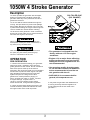
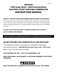
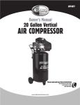
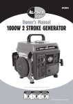
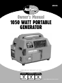
APG3006
TM
Owner’s Manual
1050 WATT PORTABLE
GENERATOR
HAVE QUESTIONS
OR NEED SERVICE
DO NOT RETURN
TO STORE
866.393.3968
DES QUESTIONS
BESOIN D’UNE RÉPARATION
PREGUNTAS O
NECESITA SERVICIO
NE PAS RETOURNER POR FAVOR NO
REGRESE A TIENDA
AU MAGASIN
866.393.3968
866.393.3968
www.allpoweramerica.com
1050W 4 Stroke Generator
Table of Contents
1. DESCRIPTION ------------------------------------------------------------------------------------------------- 2
2. UNPACKING ---------------------------------------------------------------------------------------------------- 2
3. GENERAL SAFETY ------------------------------------------------------------------------------------------- 2
4. OPERATION ---------------------------------------------------------------------------------------------------- 3
PRE-OPERATION ----------------------------------------------------------------------------------- 3
GROUNDING ---------------------------------------------------------------------------------------- 4
DC APPLICATION ---------------------------------------------------------------------------------- 4
STARTING ------------------------------------------------------------------------------------------- 4
ENGINE BREAK-IN -------------------------------------------------------------------------------- 5
GENERATOR SHUT OFF ------------------------------------------------------------------------ 5
LOAD AND PROTECTOR ------------------------------------------------------------------------ 5
OIL WARNING SYSTEM ------------------------------------------------------------------------- 5
5. MAINTENANCE ------------------------------------------------------------------------------------------ 6
INFREQUENT USAGE ------------------------------------------------------------------------------- 6
STORAGE-------------------------------------------------------------------------------------------- 6
MAINTENANCE SCHEDULE-------------------------------------------------------------------- 7
6. TROUBLESHOOTING ---------------------------------------------------------------------------------- 8
7. WIRING DIAGRAM ------------------------------------------------------------------------------------- 9
8. EXPLODED VIEW--------------------------------------------------------------------------------------- 10
9. PARTS LIST---------------------------------------------------------------------------------------------- 11
SPECIFICATION
TYPE
GENERATOR
ENGINE
UNIT
Single-phase, brushless
Voltage
120V
Max Power
1050w
Rated Power
950kw
Type
1-cylinder,
Displacement
80.7 cc
Rated Power
1.32kw/3600rpm
Fuel
Unleaded gasoline
Oil
SAE 10W-30
4-stroke, forced air cooling gasoline engine
Oil capacity
13.5 oz.
Fuel tank capacity
1.1-gallons
Dimensions
17.3” 12.6 ” 16.1”
(L W H)
Noise
<=65dB(A)
Net weight
56 lbs.
WARNING! READ AND UNDERSTAND ALL SAFETY PRECAUTIONS IN
THIS MANUAL BEFORE OPERATING. FAILURE TO COMPLY WITH
INSTRUCTIONS IN THIS MANUAL COULD RESULT IN PERSONAL
INJURY, PROPERTY DAMAGE, AND/ OR VOIDING OF YOUR
WARRANTY. ALL POWER AMERICA WILL NOT BE LIABLE FOR ANY
DAMAGE BECAUSE OF FAILURE TO FOLLOW THESE INSTRUCTIONS.
1
1050W 4 Stroke Generator
Description
This generator is powered by an air-cooled, four-stroke, OHV engine.
2
1
3
7
4
1. Fuel tank cap
2. Safty label
3.Control panel
4.Generator nameplate
5. Starting handle
6. Fuel petcock
7. Carburetor choke lever
8. DC circuit fuse
9. AC circuit fuse
10. AC output socket
11. DC output socket
12. Pilot lamp
13. Engine ignition switch
14.Oil warning indicator lamp
6
5
9
8
10
11
12
13
14
AC
PILOT LAMP
OIL WARNING
ON
DC
OFF
CIRCUIT FUSE
AC SOCKET
12V DC/8.3A
ENG.S.W.
UNPACKING
When unpacking the generator, carefully inspect for any damage that may have occured during
shipment. Make sure any loose fittings, bolts, etc., are tightened before putting unit into service.
GENERAL SAFETY
7. Keep all persons away from the generator
during operation.
1. Before starting or servicing any generator,
read and understand all instructions. Failure to
follow safety precautions or instructions can
cause equipment damage and/or serious
personal injury. Retain all manuals for future
reference.
8. Do not allow persons wearing loose clothing or
jewelry to start or operate the generator. Loose
clothing or jewelry may become entangled in
moving components causing equipment damage
and/or personal injury.
2. Never use this generator for any application
other than that specified by the manufacturer.
Never operate this generator under conditions
not approved by the manufacturer. Never
attempt to modify this generator to perform in
any manner not intended by the manufacturer.
9. While in operation, keep all persons away from
the immediate area surrounding your generator.
3. For maintenance and repairs, use only products
and parts recommended by the manufacturer.
Do not operate this generator on wet surfaces or
in the rain.
4. Be sure that the generator is properly
grounded to an external ground path prior to
operation. Refer to the section entitled
“Grounding Instructions” for proper grounding
procedures.
10. Be sure all powered devices are shut off prior
to connecting them to the generator.
11. Keep the generator clean and well maintained
at all times.
12. Be sure that all tools and appliances are in
good repair and are properly grounded. Use
devices that have three prong power cords. If a
extension cord is used, be sure that it has three
prongs for proper grounding.
5. Be sure that the generator is operated only by
persons who have read and understand these
instructions.
6. Be sure that the generator is placed on a flat
level surface prior to and during operation. The
generator must not slide or shift during
operation.
2
1050W 4 Stroke Generator
Description
OIL FILLER CAP
(OIL GAUGE)
13. Never operate the generator with damaged,
broken or missing parts. DO NOT operate the
generator while any of the protective shrouds or
guards are removed.
14. Do not refill the fuel tank while the engine is
running. Use precautions to prevent fuel spillage
during refills. Be sure the fuel tank cap is securely
in place before starting the engine. Allow engine to
cool for at least two minutes before refueling.
15. Be sure to store gasoline in clean containers
that do not contain water, dirt or rust because this
will cause the engine to shut down.
Never operate this generator in an explosive
atmosphere, inside your home or basement, or
any other poorly ventilated area.
Shut off the generator engine and disconnect
the spark plug wire before performing any
service or maintenance to the unit.
• The generator is shipped from the
factory without oil in the engine
crankcase.
OPERATION
• Engine oil is a major factor affecting
engine performance and service life.
Detergent oils and vegetable oils are
not recommended.
PRE-OPERATION
1. Check fuel level before starting your generator.
Always use clean, unleaded, mid-to-premium
grade gasoline for best results. Do not overfill and
allow some space at the top of the tank for
expansion. We recommend that you use unleaded
fuel because it produces fewer engine and spark
plug deposits and extends the life of exhaust
system components. Using lower octane
gasoline can cause persistent “pinging” or
heavy “spark knock” which, if severe, can lead
to engine damage. If “spark knock” or
“pinging” occurs at a steady engine speed
under normal load, change brands of gasoline.
• Use premium quality 4-stroke motor
oil. Do not add commercial additives
to the recommended oil and do not
mix gasoline with the oil.
• SAE 10W-30 is recommended for
general, all-temperature use.
3. Only after the generator has stabilized and
is running smoothly should an appliance or
tool be plugged into the AC outlet of the
generator.
2. Check oil level before starting the engine. The
oil level should be positioned between the lower
and upper marks of the oil fill cap shown.
3
1050W 4 Stroke Generator
Grounding
STARTING
1. Use the ground terminal on
the generator to connect the
unit to a suitable ground
source. Securely fasten the
end terminal of the ground wire to the ground
terminal on the generator.
1. Remove all electrical loads from the generator.
2. Set the fuel switch to the open (ON) position.
3. Turn the engine switch in “ON” position.
4. Move the choke/run lever to the choke position.
2. A 10-gauge copper wire should be used to
connect the ground terminal of the generator to
the grounding rod. A wire that is too thin may not
provide sufficient electrical current carrying
capacity to be an adequate ground path.
5. Pull the starter rope with a brisk smooth motion.
6. Return choke/run lever to the switch to the run
position.
7. After starting the generator, allow the engine to
run for 2-3 minutes to stabilize before applying a
load.
3. The other end of the ground wire must be
securely fastened to an approved ground source.
Refer to the local regulations for ground source
information. If not sure of regulations or
procedures, obtain assistance from a qualified
(licensed or certified) electrical technician.
NEVER attempt to modify or adjust either the
engine speed or the output voltage of your
generator when it works normally.
DC APPLICATION
1. The DC output is
designed for charging a
12-volt battery only.
2. The “+” (positive)
terminal or the battery
must be connected to the
DC “+” terminal on the
generator, and the ““(negative) terminal of the
battery must be connected
to the DC “-“ terminal on
the generator.
Never operate your generator under
these conditions:
Operate your generator only after
you have:
1. Rain or inclement weather
2. Excessive vibration
3. Sparking
4. Electric output loss
5. Changing or fluctuating engine
speed
6. Overheating in connected equipment
7. Damaged receptacles
8. Engine misfire
9. Damaged, broken or missing parts
10. Shrouds/guards removed
1. Read and understand these
instructions
2. Clear immediate area of all
persons
3. Properly grounded the generator
4. Properly grounded any tools or
appliances that you’ll be operating
5. Placed the generator on a flat,
level surface
6. Placed the generator in a well
ventilated area
4
1050W 4 Stroke Generator
Operation
Open fuel tank
LOAD AND PROTECTOR
Engine Switch to
On position
Move choke lever
to CHOKE position
RUN
Plug in tool or
appliance
After starting
Unplug tool or appliance
CHOKE
Start engine
Engine switch to Off position
Move choke lever
to RUN position
ENGINE BREAK-IN
The break-in period for the generator’s engine is
the first 25 hours of operation. During this
timeframe, DO NOT exceed 75% of the
generator’s load limit. In other words, the
maximum load during this break-in period should
be no more than 700 watts.
Close fuel
1. Total combined load
through any combination of
receptacles must not exceed
rated power of generator.
ALWAYS check the oil level before starting.
When checking the oil, screw in the dipstick
slowly until it bottoms. If running the
generator for extended periods of time,
check the oil level every eight hours or at
least daily. Change oil after the first 8 hours
of operation; thereafter, change the oil every
50 hours of operation. If operating the
generator under heavy load or in high
ambient temperature, change the oil every 25
hours of operation.
FUSE
CIRCUIT FUSE
2. Reduce load if AC fuse or
DC fuse melt and change
another fuse.
NOTE:
Power draw can be calculated by multiplying
volts and amps. The resulting number is
wattage. Never exceed the posted maximum
wattage for the generator or any individual
receptacle. Refer to owner’s manuals and
product tags to determine the wattage of
electrical load devices. Long power cords and
extension cords draw additional power. Keep
cord lengths at a minimum.
GENERATOR SHUT-OFF
1. Remove all electrical load devices from the
generator.
2. Allow the engine to run for 2-3 minutes with
no electrical load.
3. Turn engine switch off. This will stop the
engine.
4. Set the fuel switch to closed (OFF) position.
5. Verify that the generator has completely
stopped.
6. Allow the unit to cool before placing in
storage.
ESTIMATED POWER USAGE
Load Device
Computer
CD Player
VCR
Radio
Television
Microwave
Blender
Receiver
5
Watts
Load Device
300
100
100
100
300
800
800
420
Hand Vacuum
Power Drill
Hedge Trimmer
Weed Wacker
Coffee Maker
Outdoor Lights
Bug Light
Cooker/Frying Pan
Watts
500
500
500
500
1200
75-150
50
200
1050W 4 Stroke Generator
Maintenance
INFREQUENT USAGE
If the generator is used infrequently, starting
difficulties may occur. To help prevent this
from happening, the generator should be
started and run for approximately 30 minutes
each week.
4. Pour approximately one teaspoon of oil into
spark plug hole.
5. Pull starter cord several times to spread the
oil throughout the cylinder.
6. Slowly pull the starter cord until resistance
is left. This indicates that the piston is moving
upward on the compression cycle, and the
intake and exhaust valves are closed. The
piston pushes a small amount of air from the
spark plug hole on compression.
STORAGE
If the generator is not going to be used for an
extended period of time, the following
procedures should be performed:
1. Drain all fuel from the tank, lines, and
carburetor.
7. Remove air filter from the generator, gently
wash in kerosene and let dry. Pour small
amount of motor oil onto clean air filter, gently
squeeze filter to uniformly distribute the oil,
blot excess motor oil from air filter (do not
twist filter), and replace the air filter.
0.7-0.8mm.
2. Drain oil while the engine is still warm.
3. Remove spark plug. Clean off any carbon
deposits. Check for discoloration - plug
should be tan in color. Check the gap, it
should be
6
1050W 4 Stroke Generator
Maintenance
MAINTENANCE SCHEDULE
Part
Spark plug
Oil
Valve
Clearance
Fuel Line
Exhaust
System
Carburetor
Item
Every 3
months
or 50
hours
Check and adjust
Every 6
months
or 100
hours
Every 12
Months
or 300
hours
(1)
Check fuel hose for
crack or damage.
Replace if necessary.
Check for leakage.
Retighten or replace
gasket and bolts.
Check choke lever
operation.
Check for damage.
Starting
System
Check starter
operation.
Check and clean the
element.
Generator
Bolts
First
month or
20 hours
Check condition,
adjust gap and clean.
Replace or fill if
necessary
Check oil level.
Replace or fill if
necessary.
Cooling Fan
Air Cleaner
Before
every
starting
(2)
Check and tighten.
(1) Valve clearance: Intake 0.13-0.20mm; exhaust 0.13-0.20mm
(2) Service more frequently when used in dusty areas.
7
1050W 4 Stroke Generator
TroubleShooting
Problem
Possible Cause
1. Engine speed is too slow
Zero output from
receptacles
2. Open or shorted wiring
3. Faulty capacitor
3. Replace capacitor
4. Open/ shorted rotor or stator
windings
4.Test wiring resistance, replace
winding if necessary
5. Open rectifier
5. Test rectifier, replace if necessary
1. Adjust engine speed(ask repair
shop for help)
2. Test rectifier, replace if necessary
1. Engine speed is too slow
Low output voltage
with no load
High output voltage
with no load
Low output voltage
under load
Erratic output
voltage
2. Open rectifier
3. Faulty capacitor
3. Replace capacitor
4.Open/shorted rotor or stator
windings
5. Alternator not magnetized
4.Test winding resistance, replace
winding if necessary
5. Re-magnetize the alternator
1. Faulty capacitor
1. Replace capacitor
2. Engine speed is too fast
2. Adjust engine speed
1. Open rectifier
1. Test rectifier, replace if necessary
2. Engine speed is too low at full
load
2. Adjust engine speed(ask repair
shop for help)
3. Excessive load applied
3. Reduce the applied load
1. Dirty, corroded, or loose wiring
connection
1. Referring to the wiring diagram,
clean and reconnect all wiring
2. Remove all loads, then apply each
one individually to determine which
one is causing erratic output.
1. Tighten all mountings
2. Unbalanced load applied
1. Loose generator or engine bolt
Noisy operation
Engine won’t start
Corrective Action
1. Adjust engine speed(ask repair
shop for help)
2. Clean and reconnect all wiring
3. Faulty bearing
2. Test winding resistance, replace
field winding if necessary; Test
load devices for shorts. Replace
defective load device
3. Replace bearing
1. No fuel
1. Check fuel
2. Short circuit in generator field
or load
2. Fuel switch is in closed position
2. Place fuel switch in open position
3.Engine switch is in closed
position
3. Place engine switch in open
position
4. Clean spark plug. Adjust gap,
replace if necessary
5. Check cylinder for leakage
4. Spark plug dirty or wrong gap
5. Low cylinder compression
Note: If the user is not comfortable performing any of the corrective actions mentioned in the
Troubleshooting table, please seek the assistance of your local small engine repair shop.
8
1050W 4 Stroke Generator
Wiring Diagram
E/G
OSU
SP
G/R
D1/D2
AC FU
FC
ENGINE
OIL SENDING UNIT
SPARK PLUG
GENERATOR
RECTIFIER
AC FUSE
FIELD WINDING
MC
SC
DC
PL
REC
DC FU
ENG.SW.
AC WINDING
AUXILIARY WINDING
CHARGING WINDING
PILOT LAMP
AC SOCKET
DC FUSE
ENGINE SWITCH
9
B/W
B
GR
R
Y
B/R
BL
BLACK AND WHITE
BLACK
GREEN
RED
YELLOW
BLACK AND RED
BLUE
23
10
24
22
25
21
28
27
26
20
19
18
17
16
15
14
29
30
13
32
34
31
33
12
35
36
41
40
39
38
37
16
11
28
27
42
10
56
57
9
58
16
55
43
8
44
54
45
53
7
16
52
51
50
6
49
48
3
2
5
4
46
3
1
47
59
60
61
62
3
2
1050W 4 Stroke Generator
Parts List
P
1050W 4 Stroke Generator
Parts List
No
Qty
No
1
Bolt
GB5780 M5*10
2
32
Out-fuel pipe
2
Spring Washer
GB93 5
7
33
Fuel petcock
GR1000C.05-03
1
3
Washer
GB95 5
6
34
Spring washer
GB/T93 ø6
1
4
Cover
1
35
Nut
GB/T6184 M6
1
5
Bolt
4
36
In-fuel pipe
6
Rear Cover, motor
1
37
Muffler exhaust cover
GR1000C.02-01
1
7
Stator
1
38
Base plate
GR1000C.02.03-00
1
8
Bolt
1
39
Vibration rubber pad
GR1000A-16
4
9
Rotor
1
40
Washer
GB/T96 ø 6
4
10
Bolt
GB/T5789 M6*16
4
41
Bolt
GB/T5781 M6*16
4
11
Fuel tank
GR1000C.05.01-00
1
42
Bolt
GB/T5781 M8*25
2
12
Back shroud
GR1000C.02.02-00
1
43
Capacitor mount
GR1000C.04-01
1
13
Fuel cap
GR1000C.05.02-00
1
44
Capacitor
AC 12UF 250V
1
14
Meeting set
GR1000C.05-04
1
45
Fore shroud
GR1000C.02.01-00
1
15
Spark plug
inspecting Top
GR1000C.02-03
1
46
Nut
GB/T6170 M6
2
16
Bolt
GB/T5789 M6*12
11
47
Oil inspecting top
GR1000C.02-02
1
17
Washer
GB/T95 ø 6
15
48
Engine switch
1
18
Bolt
GB/T818 M6*12
15
49
AC Outlet
1
19
Muffler guided cover
(outside)
GR1000C.03-02
1
50
Plot lamp
1
20
Self-tapping bolt
GB/T845 ST4.2*9.5
5
51
Oil warning lamp
21
Engine
A152F
1
52
Control panel
GR1000C.03-03
1
53
DC Outlet
1
GR1000C.03-04
1
54
DC Circuit breaker
1
1
22
23
Description
Cylinder head guided
cover(up)
Cylinder head guided
cover(down)
Part #
GB5780 M5*30
GR1000A-10
Description
Part #
Qty
1
1
1
GR1000C.04.01-01
1
24
Air-cleaner assembly
GR1000C.01.01-00
1
55
AC Circuit breaker
25
Nut
GB/T6184 M8
2
56
Fore cover, motor
26
Engine mount
GR1000A-17
1
57
Washer
GB97.2 8
4
27
Washer
GB/T95 ø 8
4
58
Bolt
GB5780 M8*20
4
28
Bolt
GB5781 M8*16
4
59
Washer
GB97.2 8
2
29
Oil alarmer
1
60
Spring washer
GB93 8
2
30
Muffler
GR1000C.01.02-00
1
61
Nut
GB/T6170 M8
2
31
Muffler guided cover
(inside)
GR1000C.03-01
1
62
Bolt
GB/T818 M5*10
1
FOR TECHNICAL SUPPORT PLEASE CALL
866.393.3968
All-Power America
16273 E. Gale Ave.
City Of Industry, CA 91745
626.855.0840
www.allpoweramerica.com
all rights reserved
11
1